Embed Size (px)
Citation preview
1
1
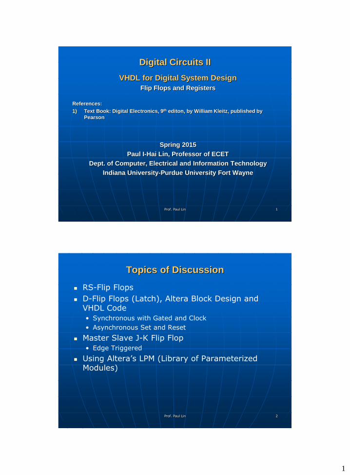
Digital Circuits II
VHDL for Digital System Design
Flip Flops and Registers
References:
1) Text Book: Digital Electronics, 9th editon, by William Kleitz, published by
Pearson
Spring 2015
Paul I-Hai Lin, Professor of ECET
Dept. of Computer, Electrical and Information Technology
Indiana University-Purdue University Fort Wayne
Prof. Paul Lin
2
Topics of Discussion
RS-Flip Flops
D-Flip Flops (Latch), Altera Block Design and VHDL Code
• Synchronous with Gated and Clock
• Asynchronous Set and Reset
Master Slave J-K Flip Flop
• Edge Triggered
Using Altera’s LPM (Library of Parameterized Modules)
Prof. Paul Lin
2
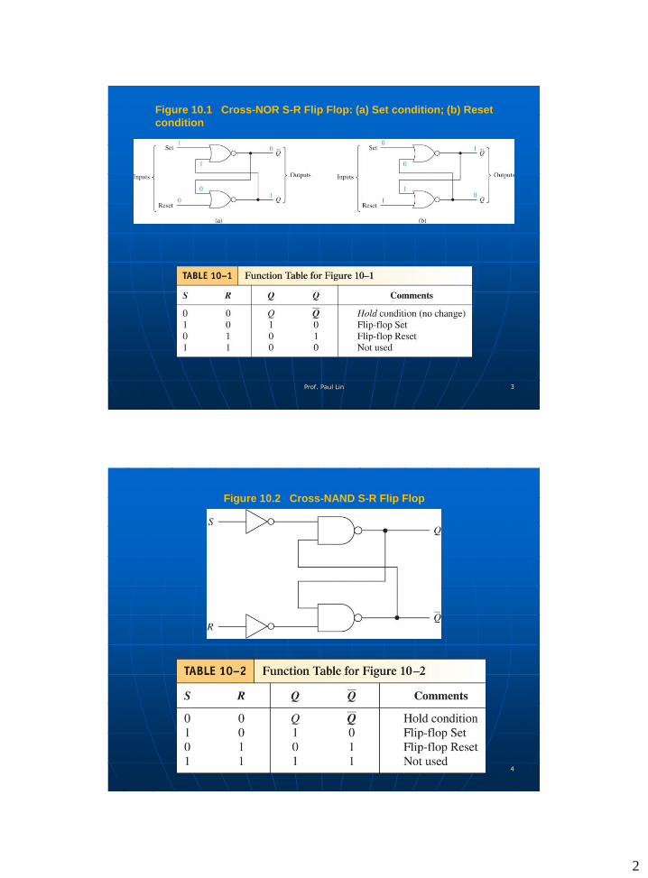
Figure 10.1 Cross-NOR S-R Flip Flop: (a) Set condition; (b) Reset
condition
Prof. Paul Lin 3
Figure 10.2 Cross-NAND S-R Flip Flop
Prof. Paul Lin 4
3
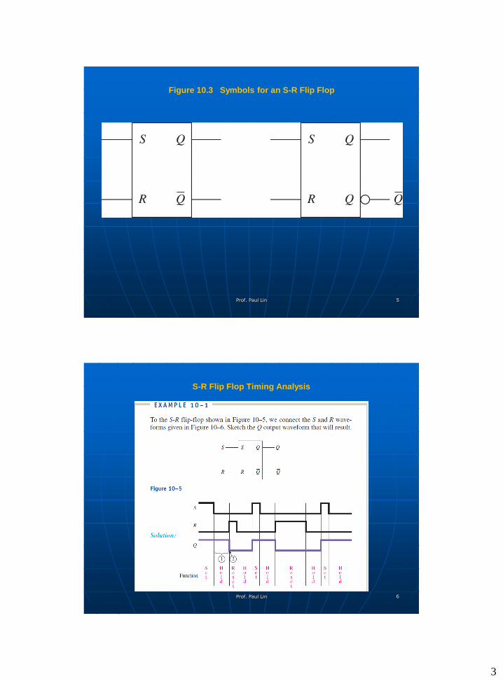
Figure 10.3 Symbols for an S-R Flip Flop
Prof. Paul Lin 5
S-R Flip Flop Timing Analysis
Prof. Paul Lin 6
4
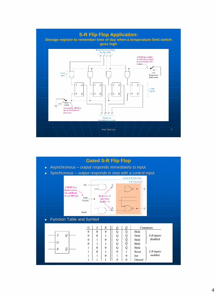
S-R Flip Flop Application: Storage register to remember time of day when a temperature limit switch
goes high
Prof. Paul Lin 7
Gated S-R Flip Flop
Asynchronous – output responds immediately to input
Synchronous – output responds in step with a control input
Function Table and Symbol
Prof. Paul Lin 8
5
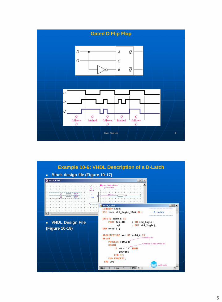
Gated D Flip Flop
Prof. Paul Lin 9
Example 10-6: VHDL Description of a D-Latch
Block design file (Figure 10-17)
VHDL Design File
(Figure 10-18)
Prof. Paul Lin 10
6
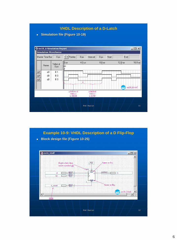
VHDL Description of a D-Latch
Simulation file (Figure 10-19)
Prof. Paul Lin 11
Example 10-9: VHDL Description of a D Flip-Flop
Block design file (Figure 10-25)
Prof. Paul Lin 12
7
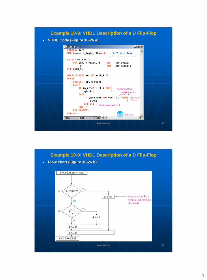
Example 10-9: VHDL Description of a D Flip-Flop
VHDL Code (Figure 10-26 a)
Prof. Paul Lin 13
Example 10-9: VHDL Description of a D Flip-Flop
Flow chart (Figure 10-26 b)
Prof. Paul Lin 14
8
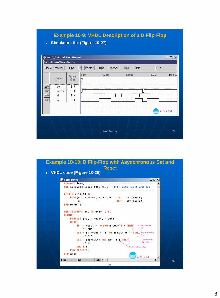
Example 10-9: VHDL Description of a D Flip-Flop
Simulation file (Figure 10-27)
Prof. Paul Lin 15
Example 10-10: D Flip-Flop with Asynchronous Set and
Reset VHDL code (Figure 10-28)
Prof. Paul Lin 16
9
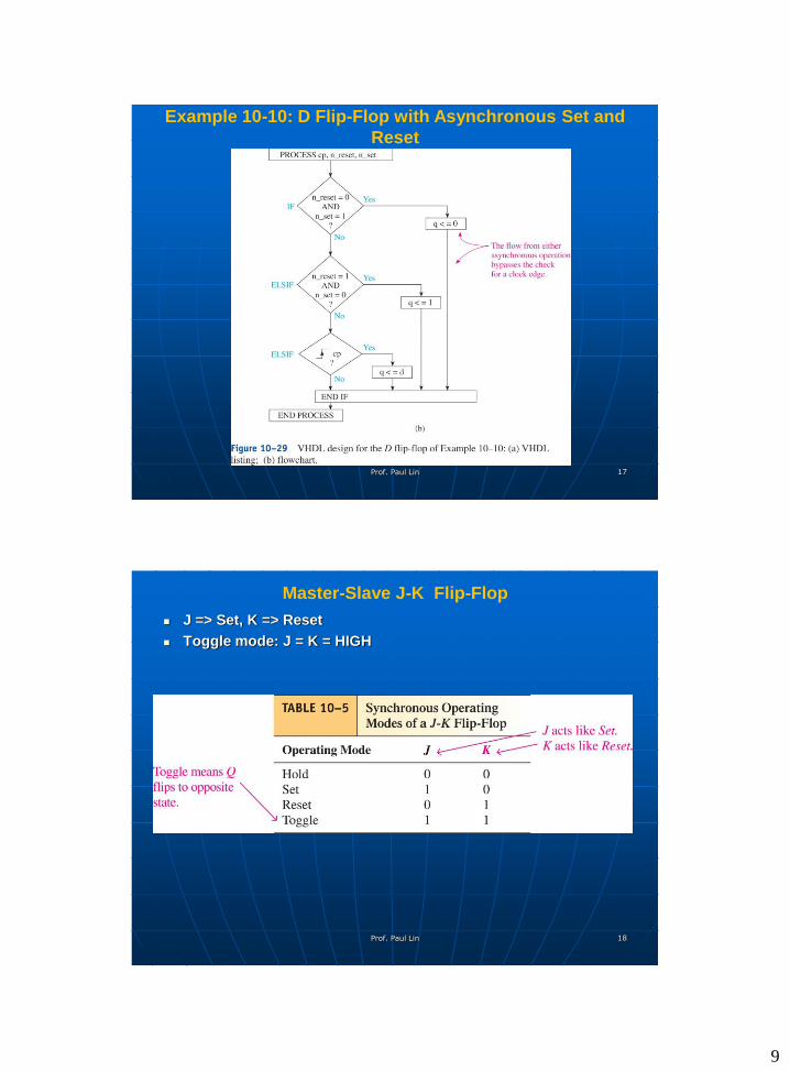
Example 10-10: D Flip-Flop with Asynchronous Set and
Reset
Prof. Paul Lin 17
Master-Slave J-K Flip-Flop
J => Set, K => Reset
Toggle mode: J = K = HIGH
Prof. Paul Lin 18
10
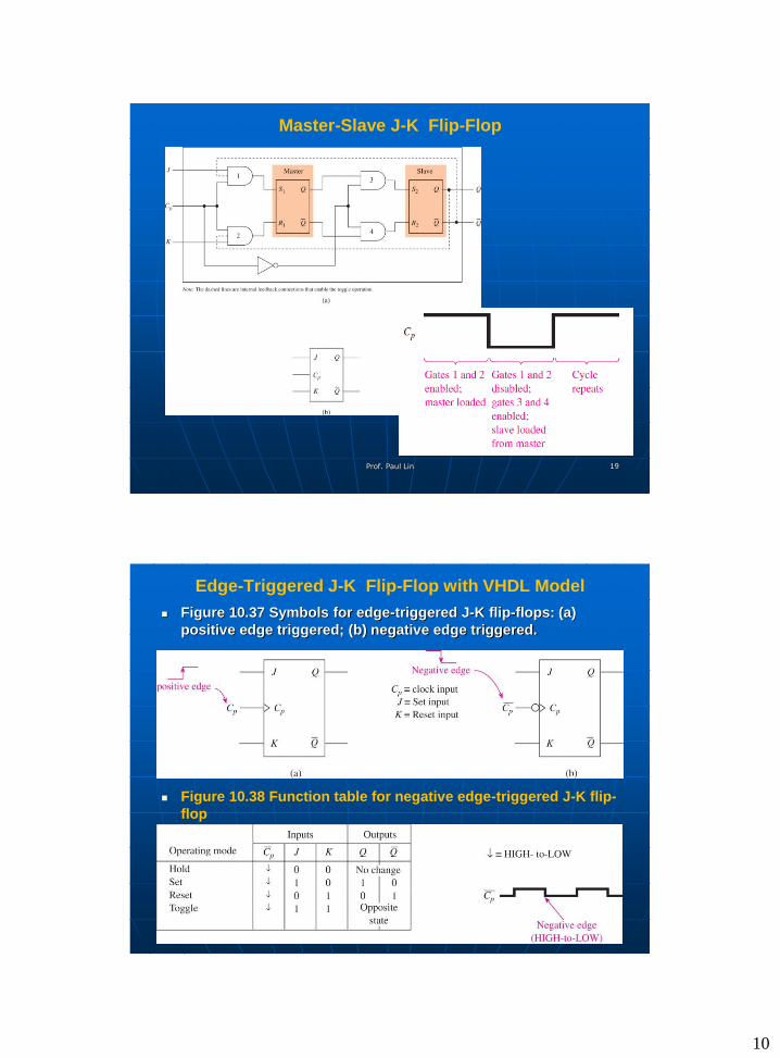
Master-Slave J-K Flip-Flop
Prof. Paul Lin 19
Edge-Triggered J-K Flip-Flop with VHDL Model
Figure 10.37 Symbols for edge-triggered J-K flip-flops: (a)
positive edge triggered; (b) negative edge triggered.
Figure 10.38 Function table for negative edge-triggered J-K flip-
flop
Prof. Paul Lin 20
11
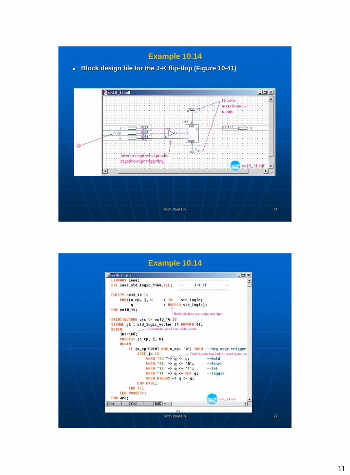
Example 10.14
Block design file for the J-K flip-flop (Figure 10-41)
Prof. Paul Lin 21
Example 10.14
Prof. Paul Lin 22
12
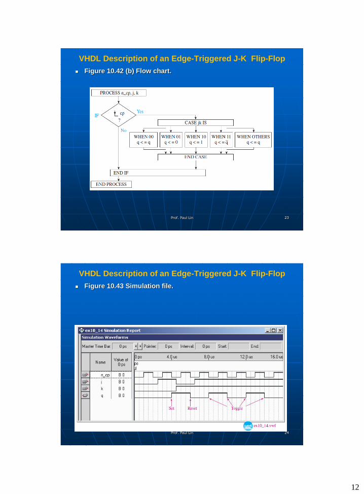
VHDL Description of an Edge-Triggered J-K Flip-Flop
Figure 10.42 (b) Flow chart.
Prof. Paul Lin 23
VHDL Description of an Edge-Triggered J-K Flip-Flop
Figure 10.43 Simulation file.
Prof. Paul Lin 24
13
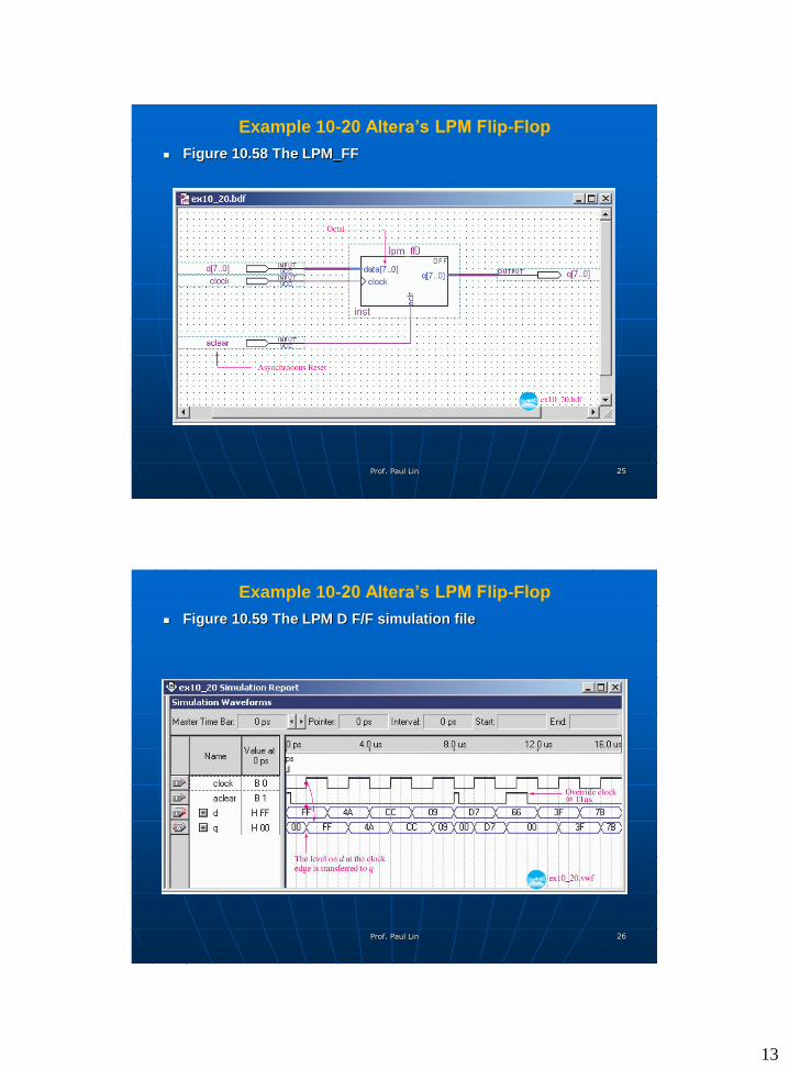
Example 10-20 Altera’s LPM Flip-Flop
Figure 10.58 The LPM_FF
Prof. Paul Lin 25
Example 10-20 Altera’s LPM Flip-Flop
Figure 10.59 The LPM D F/F simulation file
Prof. Paul Lin 26
14
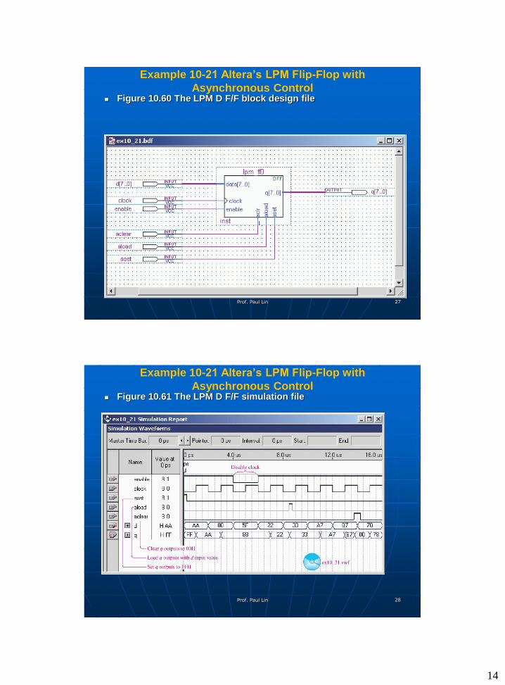
Example 10-21 Altera’s LPM Flip-Flop with
Asynchronous Control Figure 10.60 The LPM D F/F block design file
Prof. Paul Lin 27
Example 10-21 Altera’s LPM Flip-Flop with
Asynchronous Control Figure 10.61 The LPM D F/F simulation file
Prof. Paul Lin 28
15
Summary & Conclusion
Prof. Paul Lin 29