Embed Size (px)
Citation preview
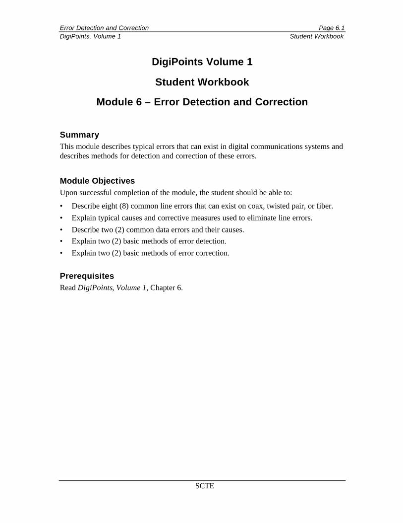
Error Detection and Correction Page 6.1 DigiPoints, Volume 1 Student Workbook
SCTE
DigiPoints Volume 1
Student Workbook
Module 6 – Error Detection and Correction
Summary This module describes typical errors that can exist in digital communications systems and describes methods for detection and correction of these errors.
Module Objectives Upon successful completion of the module, the student should be able to:
• Describe eight (8) common line errors that can exist on coax, twisted pair, or fiber. • Explain typical causes and corrective measures used to eliminate line errors. • Describe two (2) common data errors and their causes. • Explain two (2) basic methods of error detection. • Explain two (2) basic methods of error correction. Prerequisites Read DigiPoints, Volume 1, Chapter 6.

Error Detection and Correction Page 6.2 DigiPoints, Volume 1 Student Workbook
SCTE
On what type of media will these types of problems be commonly found?
Line Errors
Line Error Problem Corrected by Attenuation Distortion C Conditioning Envelope Delay Distortion C Conditioning Signal-to-Noise Ratio D Conditioning Harmonic Distortion D Conditioning Jitter Various Controls Impulse Noise Various Controls Frequency Shift Various Controls Echo Various Controls

Error Detection and Correction Page 6.3 DigiPoints, Volume 1 Student Workbook
SCTE
What is happening to the power levels of the two frequencies?
If the square wave consisted of an “infinite” number of different sine waves, explain what happens to the square wave as it travels down the medium.
What variables have to be addressed to prevent attenuation distortion from making the signal unreadable?
Attenuation Distortion
F1
F2
F1
F2

Error Detection and Correction Page 6.4 DigiPoints, Volume 1 Student Workbook
SCTE
What is happening with respect to the three frequencies as it relates to their appearance on arrival? (NOTE: These signals all started at the same time.)
If the square wave consisted of an “infinite” number of different sine waves, explain what happens to the square wave as it travels down the medium.
What variables have to be addressed to prevent envelope delay distortion from making the signal unreadable?
Can the signal be affected by only one of these types of distortions? Why?
Envelope Delay Distortion
F1
F2
F1
F2
F3 F3

Error Detection and Correction Page 6.5 DigiPoints, Volume 1 Student Workbook
SCTE
Line Conditioning There are two types of conditioning that can be done on circuits riding on twisted pair. The two types of conditioning are known as C Conditioning and D Conditioning.
C Conditioning What types of impairments does C Conditioning address?
What types of lines can C Conditioning be used on?
How many types of C Conditioning are there?
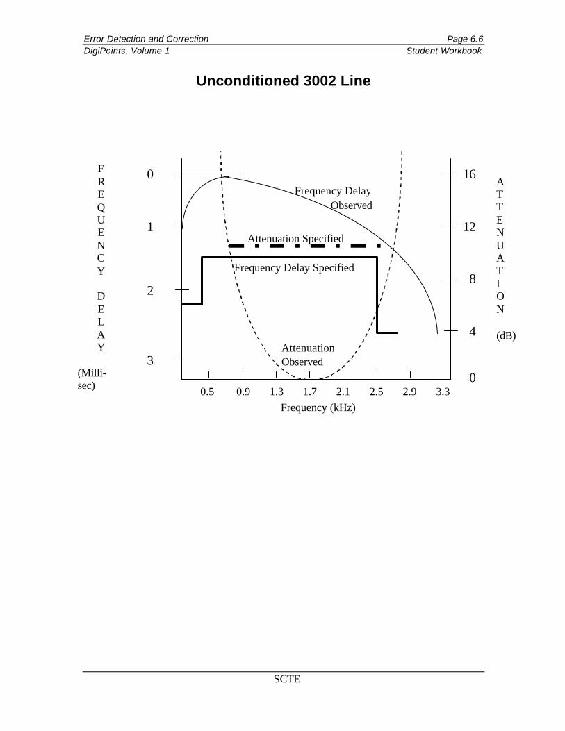
Error Detection and Correction Page 6.6 DigiPoints, Volume 1 Student Workbook
SCTE
Unconditioned 3002 Line
Frequency Delay Observed
16
12
8
4
0
0
1
2
3
F R E Q U E N C Y
D E L A Y
(Milli-sec)
A T T E N U A T I O N (dB)
Frequency (kHz) 0.5 0.9 1.3 1.7 2.1 2.5 2.9 3.3
Attenuation Observed
Attenuation Specified
Frequency Delay Specified
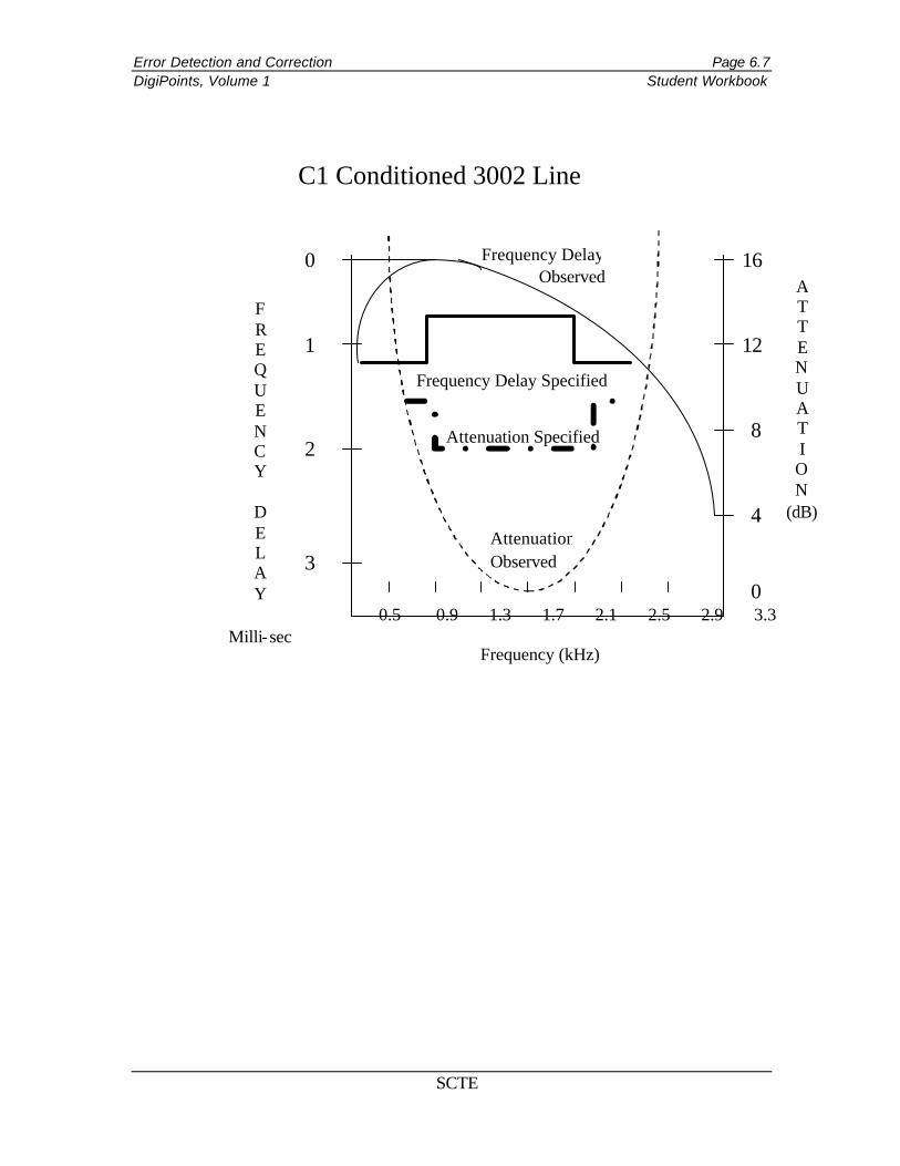
Error Detection and Correction Page 6.7 DigiPoints, Volume 1 Student Workbook
SCTE
16
12
8
4
0
0
1
2
3
F R E Q U E N C Y
D E L A Y
Milli-sec
A T T E N U A T I O N
(dB)
Frequency (kHz)
0.5 0.9 1.3 1.7 2.1 2.5 2.9 3.3
Frequency Delay Observed
Attenuation Observed
Attenuation Specified
Frequency Delay Specified
C1 Conditioned 3002 Line
Error Detection and Correction Page 6.8 DigiPoints, Volume 1 Student Workbook
SCTE
16
12
8
4
0
0
1
2
3
F R E Q U E N C Y
D E L A Y
Milli-sec
A T T E N U A T I O N
(dB)
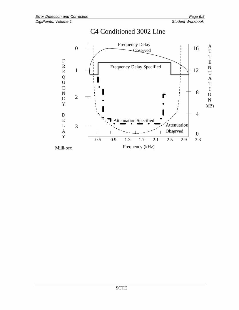
Frequency (kHz) 0.5 0.9 1.3 1.7 2.1 2.5 2.9 3.3
Frequency Delay Observed
Attenuation Observed
Attenuation Specified
Frequency Delay Specified
C4 Conditioned 3002 Line
Error Detection and Correction Page 6.9 DigiPoints, Volume 1 Student Workbook
SCTE
How does S/N differ from C/N?
Where is the S/N typically measured and by whom?
Where is the C/N typically measured and by whom?
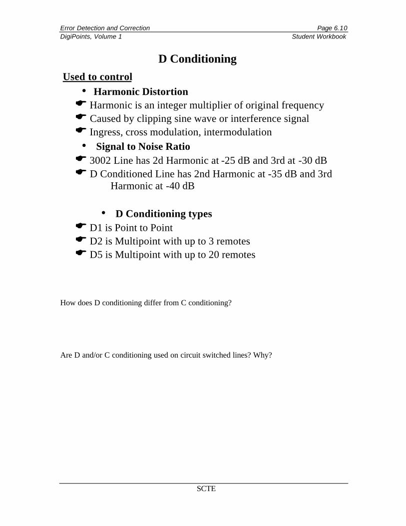
Error Detection and Correction Page 6.10 DigiPoints, Volume 1 Student Workbook
SCTE
How does D conditioning differ from C conditioning?
Are D and/or C conditioning used on circuit switched lines? Why?
D Conditioning Used to control
• Harmonic Distortion E Harmonic is an integer multiplier of original frequency E Caused by clipping sine wave or interference signal E Ingress, cross modulation, intermodulation
• Signal to Noise Ratio E 3002 Line has 2d Harmonic at -25 dB and 3rd at -30 dB E D Conditioned Line has 2nd Harmonic at -35 dB and 3rd
Harmonic at -40 dB
• D Conditioning types E D1 is Point to Point E D2 is Multipoint with up to 3 remotes E D5 is Multipoint with up to 20 remotes

Error Detection and Correction Page 6.11 DigiPoints, Volume 1 Student Workbook
SCTE
Name two types of jitter.
What is jitter?
What is the Unit Interval?
What type of problems can jitter cause? How?
Jitter
Timing Jitter
Timing
Voltage
Ideal Clock Jitter Clock
Timing Jitter
J1 J2 J3 J4 J5
Error Detection and Correction Page 6.12 DigiPoints, Volume 1 Student Workbook
SCTE
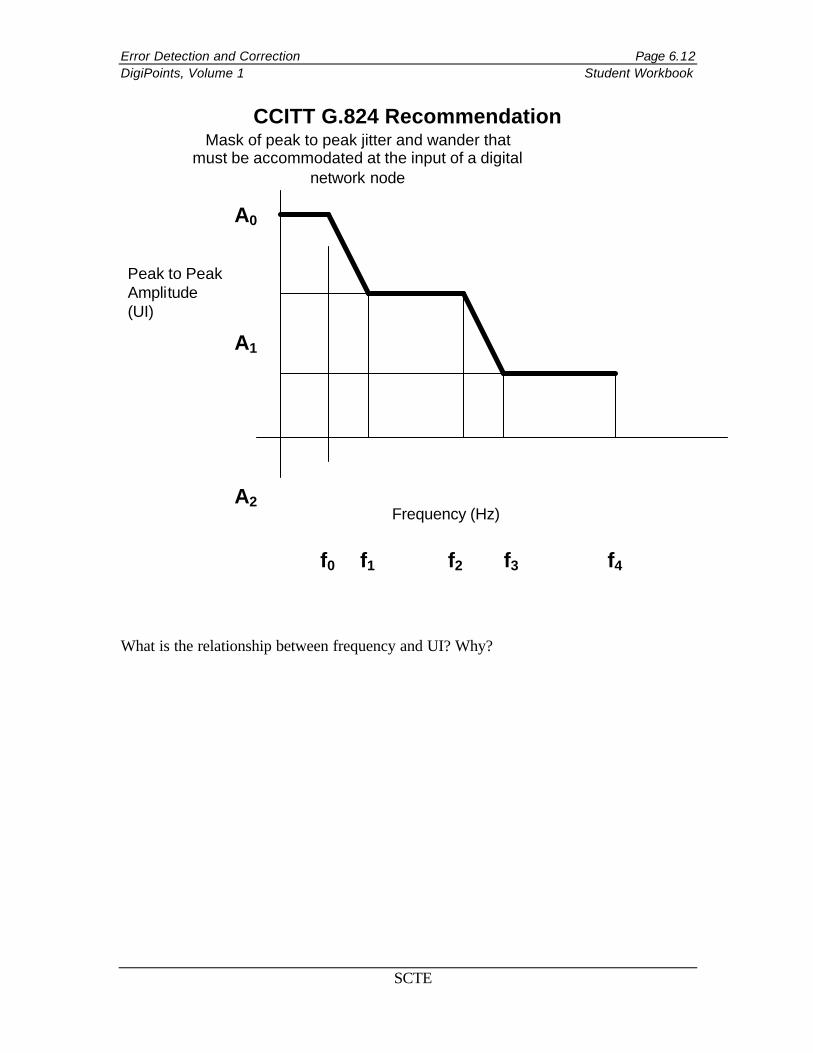
CCITT G.824 Recommendation
What is the relationship between frequency and UI? Why?
A0
A1
A2
f0 f1 f2 f3 f4
Frequency (Hz)
Peak to Peak Amplitude (UI)
Mask of peak to peak jitter and wander that must be accommodated at the input of a digital
network node

Error Detection and Correction Page 6.13 DigiPoints, Volume 1 Student Workbook
SCTE
What type of packet network could be used to carry CATV signals?
How can PCR jitter impact the information being carried?
How could this be prevented?
Peak Cell Rate Jitter
• Packet network • Cells travel to distant end over
different paths • During peak busy hours
problems can occur E Cells lost E Cells excessively delayed E Results in signal degradation
• To avoid this need either larger buffers OR greater committed bandwidth for the service
Error Detection and Correction Page 6.14 DigiPoints, Volume 1 Student Workbook
SCTE
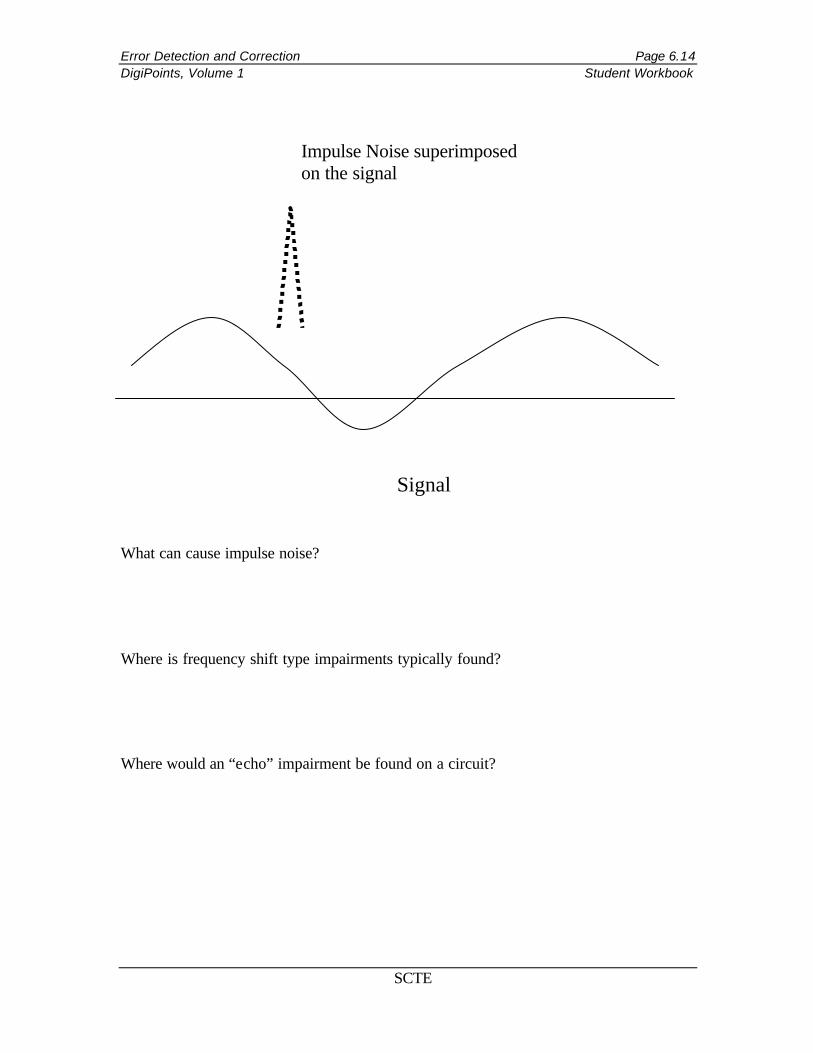
What can cause impulse noise?
Where is frequency shift type impairments typically found?
Where would an “echo” impairment be found on a circuit?
Signal
Impulse Noise superimposed on the signal

Error Detection and Correction Page 6.15 DigiPoints, Volume 1 Student Workbook
SCTE
Data Errors What are two causes of data errors?
How does the Committed Information Rate contribute to data errors?
What is meant by “Data collision”?
Error Detection and Correction Page 6.16 DigiPoints, Volume 1 Student Workbook
SCTE
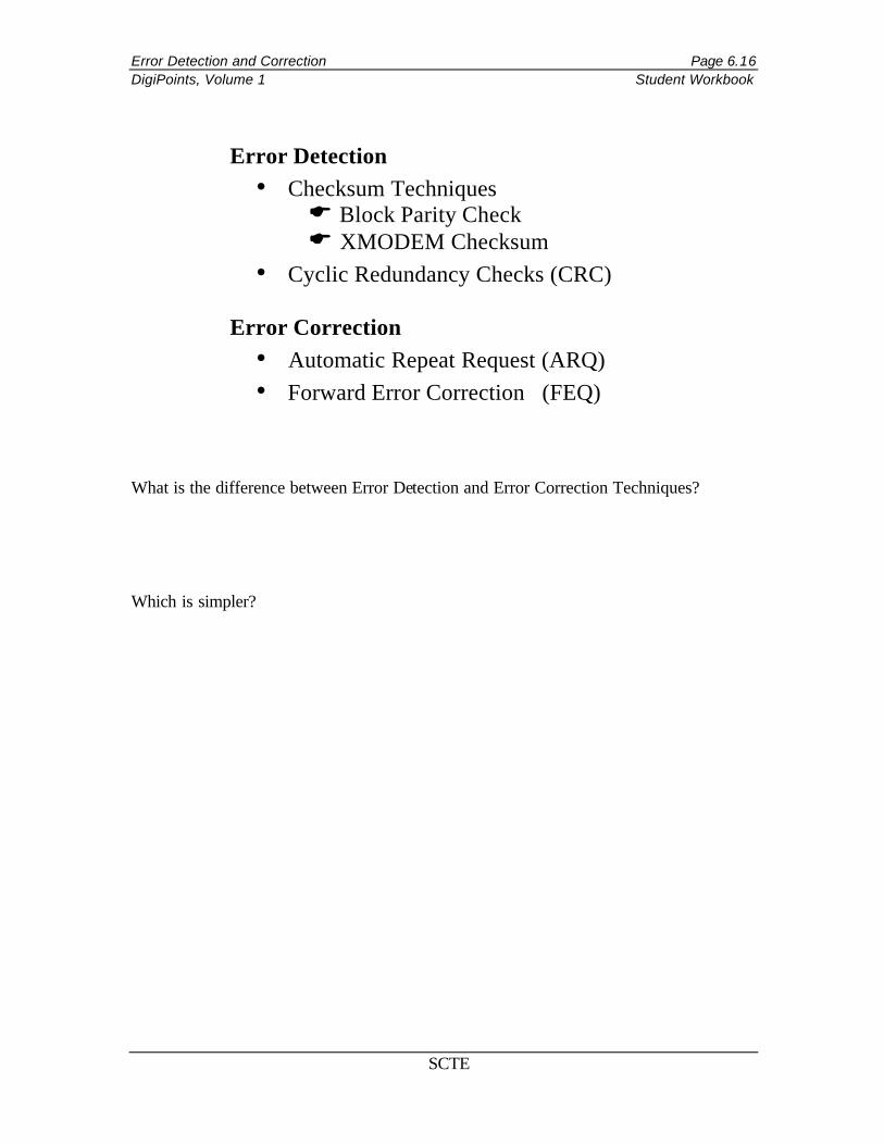
What is the difference between Error Detection and Error Correction Techniques?
Which is simpler?
Error Detection • Checksum Techniques E Block Parity Check E XMODEM Checksum
• Cyclic Redundancy Checks (CRC)
Error Correction • Automatic Repeat Request (ARQ) • Forward Error Correction (FEQ)

Error Detection and Correction Page 6.17 DigiPoints, Volume 1 Student Workbook
SCTE
BLOCK PARITY CHECK
What is another name for this type of error detection method?
How are the parity bits used?
How many errors per block can be detected using this method?
0 1 0 0 1 1 0 1 11 1 1 0 0 1 0 0 10 0 0 1 0 0 1 1 01 1 0 1 0 1 1 0 00 1 0 1 1 0 0 1 11 1 0 1 0 1 1 1 10 0 0 1 0 1 1 0 00 0 0 0 1 0 1 1 0
Bit Position
1 2 3 4 5 6 7
Character Parity
Block Parity Character

Error Detection and Correction Page 6.18 DigiPoints, Volume 1 Student Workbook
SCTE
What type of equipment frequently uses this method?
Describe how the XMODEM Checksum works.
When and where does the calculation for the XMODEM Checksum occur?
XMODEM Checksum
SOH 128 Characters of Data Block Number
Checksum
Error Detection and Correction Page 6.19 DigiPoints, Volume 1 Student Workbook
SCTE
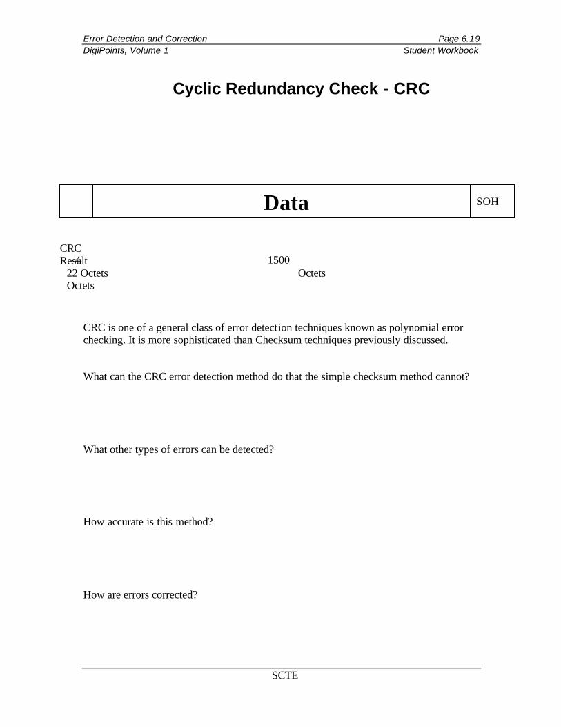
CRC is one of a general class of error detection techniques known as polynomial error checking. It is more sophisticated than Checksum techniques previously discussed.
What can the CRC error detection method do that the simple checksum method cannot?
What other types of errors can be detected?
How accurate is this method?
How are errors corrected?
Cyclic Redundancy Check - CRC
SOH Data
CRC Result
4 1500 22 Octets Octets Octets

Error Detection and Correction Page 6.20 DigiPoints, Volume 1 Student Workbook
SCTE
What method is used by ARQ to correct errors?
On what type of system is the Stop and Wait ARQ most effective? Why?
What are the two possible methods that can be employed in a Continuous ARQ environment?
How are these two methods different?
Which is most widely used? Why?
Automatic Repeat Request (ARQ)
Works in conjunction with an error detection method Two ARQ techniques:
• Stop and Wait
• Continuous
Error Detection and Correction Page 6.21 DigiPoints, Volume 1 Student Workbook
SCTE
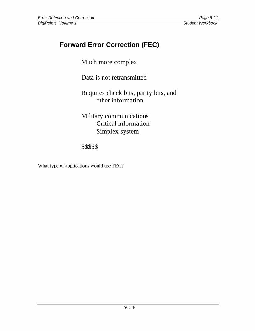
What type of applications would use FEC?
Forward Error Correction (FEC)
Much more complex Data is not retransmitted Requires check bits, parity bits, and other information Military communications Critical information Simplex system $$$$$
Error Detection and Correction Page 6.22 DigiPoints, Volume 1 Student Workbook
SCTE
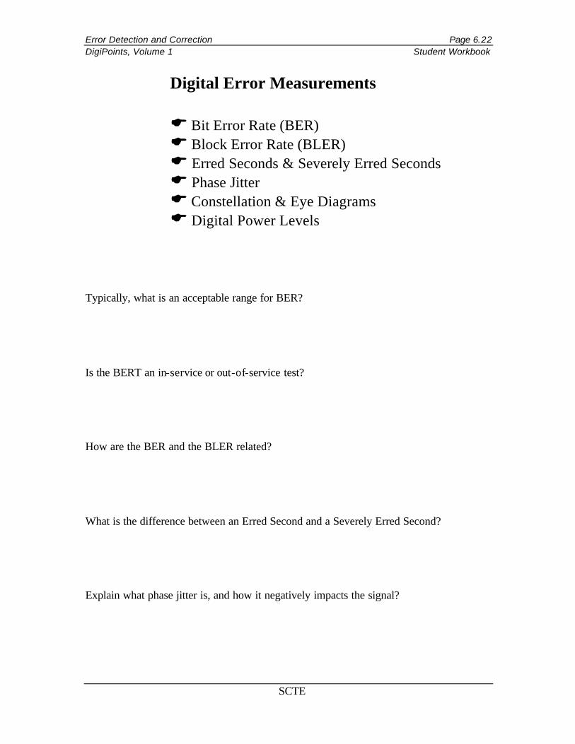
Typically, what is an acceptable range for BER?
Is the BERT an in-service or out-of-service test?
How are the BER and the BLER related?
What is the difference between an Erred Second and a Severely Erred Second?
Explain what phase jitter is, and how it negatively impacts the signal?
Digital Error Measurements
E Bit Error Rate (BER) E Block Error Rate (BLER) E Erred Seconds & Severely Erred Seconds E Phase Jitter E Constellation & Eye Diagrams E Digital Power Levels
Error Detection and Correction Page 6.23 DigiPoints, Volume 1 Student Workbook
SCTE
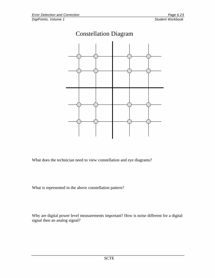
What does the technician need to view constellation and eye diagrams?
What is represented in the above constellation pattern?
Why are digital power level measurements important? How is noise different for a digital signal then an analog signal?
Constellation Diagram

Error Detection and Correction Page 6.24 DigiPoints, Volume 1 Student Workbook
SCTE
Study Questions 1. Name the two places where errors may be generated in a digital system.
2. Name the four types of line impairment that may be corrected by line conditioning, and identify which type of conditioning corrects which type of impairment.
3. Name two types of jitter, and describe what effect each one has on a digital signal.
4. Describe how Bit Error Rate is measured. Include a discussion of the signal source for the Bit Error Rate test in your description.
5. Why is Block Error Rate a better measurement of digital error than Bit Error Rate, and what should determine the block size for the BLER measurement to be meaningful?
Error Detection and Correction Page 6.25 DigiPoints, Volume 1 Student Workbook
SCTE
6. Describe how Automatic Repeat Request corrects errors. What is the difference between selective ARQ and Go Back N ARQ, both in terms of how they operate and in terms of buffering of data?
7. What is the difference between the constellation diagram and the eye diagram? What does each measure?
8. List some points in a cable TV system where the following digital error testing tools would be applied: Bit Error Rate Test, Constellation and Eye Diagram, Jitter test.