Embed Size (px)
Citation preview
Network Architectures Page 9.i DigiPoints, Volume 1 Leader Guide
SCTE
DigiPoints Series Volume 1
Leader Guide
Module 9 – Network Architectures Summary This module describes the two primary arrangements by which signals are carried from one location to another: circuit switched and packet switched systems.
Outcomes Students who complete this lesson will understand the basics attributes and characteristics of circuit switched systems, packet switched systems, and hybrid systems, which are composed of both types. The students will become familiar with the meaning of message units, common control, packet formats, PSTN operations, and the multi-service network architecture.
Module Objectives Upon successful completion of the module the student should be able to:
• Describe the difference between a circuit switched system and a packet switched system.
• Identify the three phases that occur in a circuit switched system. • Explain the purpose of the message unit structure. • Describe, at a high level, the functionality of the SS7 network. • List the benefits expected from the Multi-Service Network. Prerequisites Students should have read Chapter 9 of DigiPoints, Volume 1.
Length 90 minutes
Materials/Preparation • One workbook per student • Visual Aids • Instructor should read Chapter 2 of DigiPoints, Volume 1.
Network Architectures Page 9.ii DigiPoints, Volume 1 Leader Guide
SCTE
Supplies/Equipment • Dry Erase Board/Markers, chalkboard or flipchart • Masking Tape • Pointing Tool • Tent Cards Audience The intended audience will be mid- to senior-level technicians or other associates who are seeking an understanding of digital basics.
Network Architectures Page 9.iii DigiPoints, Volume 1 Leader Guide
SCTE
Module Outline This is an introductory level module that will provide a review of the following topics:
Objectives.......................................................................................................................1 Network Architectures ..................................................................................................2 Information Movement Through Networks ................................................................3 Protocol Data Units (PDUs).........................................................................................6 Packet Switched Network Routing .............................................................................7 Switched Network Architectures .................................................................................8 Multi-Service Network (MSN) ......................................................................................10 Summary ........................................................................................................................11 Appendix.........................................................................................................................12
Network Architectures Page 9.1 DigiPoints, Volume 1 Leader Guide
SCTE
Objectives EXPLAIN REFER TO WB 9.1
Tell students that when they have completed this module, they will be able to accomplish these objectives.
• Describe the difference between a circuit switched system and a packet switched system.
• Identify the three phases that occur in a circuit switched system.
• Explain the purpose of the message unit structure.
• Describe, at a high level, the functionality of the SS7 network.
• List the benefits expected from the Multi-Service Network.
Network Architectures Page 9.2 DigiPoints, Volume 1 Leader Guide
SCTE
Network Architectures ASK Introduction
What is the difference between circuit switched and packet switched systems?
What are the advantages and disadvantages of each?
Use as intro and as a way to evaluate skill base of students
EXPLAIN Why two types of systems? Explain the following about the reasons for different types of systems.
Circuit switched systems were the first type.
Uncomplicated – but tie up facilities.
Packet switched systems are more complex, but use facilities more efficiently.
Hybrids are a combination of both.
Tell students that this lesson will explain the difference between circuit and packet switched systems in detail.
Network Architectures Page 9.3 DigiPoints, Volume 1 Leader Guide
SCTE
Information Movement Through
Networks
DISPLAY VA 9.1 REFER TO WB 9.2 ASK EXPLAIN DISPLAY VA 9.2 REFER TO WB 9.3
Circuit Switching • Physical path established for the duration
of the call. • Point out:
◊ Users ◊ Nodes ◊ Connecting facilities ◊ Resources dedicated for duration of
the call When would this be most appropriate?
Answer
◊ For constant or nearly constant information flow that cannot tolerate delays in transport, such as a voice telephone call.
• Nodes ◊ Crosspoint, such as a switching
matrix ◊ Relatively expensive
• The three (3) phases ◊ Circuit establishment – finding an
idle end-to-end path and dedicating it to the connection
◊ Data transfer – moving data from one end to the other
◊ Circuit disconnect – releasing the path and making it available for other connections
Explain the evolution of switching technology.
• Switching technology evolution at Nodes ◊ Progressive control – each digit of
the destination address establishes part of the path as it is entered.
◊ Common control – address digits are stored and connections are established after several digits are received.
Use basic telephone call as example Point out advantages of common control
Network Architectures Page 9.4 DigiPoints, Volume 1 Leader Guide
SCTE
EXPLAIN DISPLAY VA 9.3 REFER TO WB 9.4 ASK DISPLAY VA 9.4 REFER TO WB 9.5
Packet Switching • Physical path established for the duration
of time to send information. • Point out:
◊ Users ◊ Nodes ◊ Connecting facilities
• Resources dedicated only for time it takes information to be sent.
◊ Shared links means billing can be based on number of packets sent or time of packets actually sent
◊ Economical for bursty data ◊ Information stored and forwarded
What is the advantage of Packet Switching?
Answer:
◊ Shared links means more information can be moved over a lesser number of physical facilities.
Packet is a unit of information of a fixed size consisting of:
• Header ◊ Addresses ◊ Sequence or order ◊ Type of information carried ◊ Other required identifiers
• Information ◊ User information ◊ Data, voice, video
Network Architectures Page 9.5 DigiPoints, Volume 1 Leader Guide
SCTE
DISPLAY VA 9.5 REFER TO WB 9.6 DISPLAY VA 9.6
Packet Exercise – 20 minutes total Guide students in performing the Packet Exercise found in Appendix. The “Network Manager” needs VA 9.1.6.
• Review Exercise ◊ Clocking ◊ Polling ◊ Routing – how paths are similar
and different ◊ Switch functions ◊ Network Manager functions ◊ Header ◊ Information
Network Architectures Page 9.6 DigiPoints, Volume 1 Leader Guide
SCTE
Protocol Data Units (PDU) DISPLAY VA 9.7 REFER TO WB 9.7
Two types of PDU
• Packet Format ◊ Corresponds to OSI Layer 3,
Protocol Data Unit • Message Format
◊ Has multiple OSI layers in packet ◊ Developed before OSI Model ◊ Has Flags to announce self
In both cases, the network is processing the information as a unit of information.
Network Architectures Page 9.7 DigiPoints, Volume 1 Leader Guide
SCTE
Packet Switched Network
Routing
DISPLAY VA 9.8 REFER TO WB 9.8
Considerations for routing.
• Performance ◊ Typically, minimize number of
nodes or hops ◊ Technology and power of
processors at node ◊ Minimum transport time objective
• Decision Time ◊ Virtual circuit – all PDUs on same
route, faster routing ◊ Datagram service – each PDU
routed individually, bypass congestion
• Decision Place ◊ Central routing control ◊ Originating node routing control ◊ Each node routing control
• Source of Information on Network Status ◊ Related to Decision Place ◊ Nodes must share information
• Routing Strategy ◊ Random routing ◊ Predetermined routing ◊ Flooding ◊ Adaptive Routing
• Adaptive Routing Update Time ◊ Network Status delivery time ◊ Continuous versus periodic ◊ Only update on node/user change
Network Architectures Page 9.8 DigiPoints, Volume 1 Leader Guide
SCTE
Switched Network Architectures DISPLAY VA 9.9 EXPLAIN WB 9.9 DISPLAY VA 9.10 REFER TO WB 9.10
Public Switched Telephone Network (PSTN) • First switched-network architecture • Circuit switched • Hierarchical control • Twisted pair technology • Position of digits in telephone number
signifies their role in call routing • First three digits in a 10 digit phone
number are the area code, which is tied to the geographical location of the call’s destination (Number Planning Area (NPA)
• Second three digits in a 10 digit phone number are the office code, which signifies a particular switch in that geographic area (NXX)
• Last four digits signify the telephone line served by that switch. (XXXX)
Point out the three industries and the three types of switching On blackboard or flipchart, cover how a call is made and the North American telephone Numbering plan, NXX-NXX-XXXX. DO NOT ERASE
DISPLAY VA 9.11 REFER TO WB 9.11 DISPLAY VA 9.12 REFER TO WB 9.12
Common Channel Signaling (CCS) • Removes signaling from PSTN
transmission path • Allows dynamic routing of calls • Packet switched architecture • Relatively low speed 56 kbps • NODE – STP: Signal Transfer Point
◊ Packet switch • SCP: Service Control Point
◊ Database storage • Mesh Network Architecture • Multiple Linkages
◊ A-Link ◊ B-Link ◊ C-Link ◊ D-Link ◊ E-Link ◊ F-Link
• CCS allows for advanced capabilities ◊ ISDN ◊ Intelligent Network ◊ Nationwide Centrex
Beginning with previous board diagram, VA 12, discuss how CCS aids in call setup. Include Point Codes (PC) and STP queries to SCP. Point out that PSTN switches determine the route and carry the call, but CCS sets up the call by routing setup messages.
Network Architectures Page 9.9 DigiPoints, Volume 1 Leader Guide
SCTE
ASK DISPLAY VA 9.13 REFER TO WB 9.13
WANs and MANs How are LANs different from WANs or MANs?
Answer:
◊ LANs were originally created to serve groups of users that are physically located in the same building or campus. They move data one unit at a time. WANs and MANs connect LANs together and move multiple data units simultaneously.
• Interconnected LANs • PAD – Packet Assembler/Disassembler
◊ Interface between LAN and WAN or MAN
◊ Converts LAN information to X.25 format
◊ Multiple X.25 protocols run under X.75
• WAN – Wide Area Network • MAN – Metropolitan Area Network
Network Architectures Page 9.10 DigiPoints, Volume 1 Leader Guide
SCTE
Multi-Service Network (MSN) DISPLAY VA 9.14 REFER TO WB 9.14
• Multiple services, one provider • Hybrid of switched and packet services
◊ Broadband switch is packet ◊ Narrow-band switch is circuit
• Service applications ◊ PPV with VCR functionality ◊ Interactive learning ◊ Interactive yellow pages or home
shopping ◊ Directed ad insertion ◊ Video games ◊ Telephone service with various
applications ◊ High-speed data services,
• Challenges ◊ Increased traffic can cause dropped
data packets ◊ Set top costs rise if the set top
becomes a full function node ◊ Services may deteriorate
Start from the headend and talk through the types and origin of various services, and the types of networks that are required for their delivery.
Network Architectures Page 9.11 DigiPoints, Volume 1 Leader Guide
SCTE
Summary • Network Architecture
◊ Circuit Switched ◊ Packet Switched
• Circuit Switched phases of connection ◊ Circuit Establishment ◊ Data Transfer ◊ Circuit Disconnect
• Switched architecture ◊ Progressive Control ◊ Common Control
• Packet architecture ◊ Packets ◊ Packet Data Unit ◊ PAD ◊ Routing Considerations
• Network Architectures ◊ PSTN ◊ CCS ◊ WANs and MANs ◊ MSN
Review these items to make sure students understand the concepts. Have students answer questions at end of WB
REFER TO WB 9.15 AND WB 9.16
Have students answer the study questions at the end of Module 9. Review the answers.
Answers in Appendix
Network Architectures Page 9.12 DigiPoints, Volume 1 Leader Guide
SCTE
Appendix
Packet Exercise Direct the students to complete this exercise. They will feel strange about doing it, but it is one of the most effective ways to demonstrate how a network uses packet switching. Read through the exercise and prepare a visual aid to help outline the process so students will get the big picture. You will need to prepare the items on the following pages ahead of time. You will also need a bell or buzzer to use as the “clock” signal.
Information for the students:
Pick a group of 9 individuals. Pick a person to be “Network manager”. This person will report how the exercise proceeded. Distribute the index cards and the envelope to the Network Manager.
• Six index cards for switches, and • One for destination • A small envelope labeled Source
Network Manager: Give each of eight persons one of the above items. Six persons are to act as switches designated by a particular number. One person will be the source, and one person will be the destination.
Source has an envelope with an original message, cut into packets. Each packet has a route through the network. Source starts the distribution. Then the switches route to the next location. The destination must reassemble the message.
Each ring of the bell is one clock cycle. The source releases one message, in alphabetical order, per clock cycle.
Switches can route only one message to the next switch per clock cycle. If more than one message arrives at a switch during the cycle, extra messages must be held for the next clock cycle. Route the lowest alphabetical message first. (A before B, etc.)
The Network manager will poll and keep track of how information flows through the network of switches at each clock cycle.
Note any problems/challenges.
Network Architectures Page 9.13 DigiPoints, Volume 1 Leader Guide
SCTE
Give the students 15 minutes!
Creating this exercise:
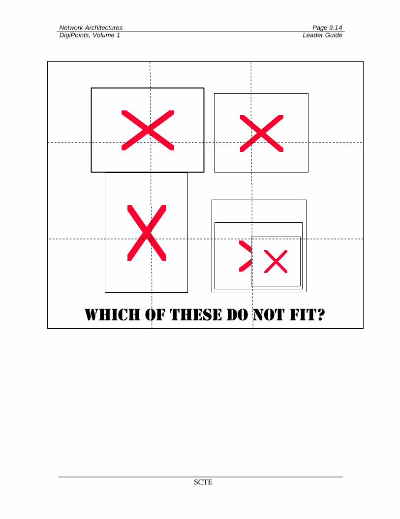
Cut the picture found on the next page along the dotted lines. This is the information to be transmitted. Using the table below the picture as a reference, label each packet and put its “route” on the reverse side of the picture.
Network Architectures Page 9.14 DigiPoints, Volume 1 Leader Guide
SCTE
Which of these do not fit?
Network Architectures Page 9.15 DigiPoints, Volume 1 Leader Guide
SCTE
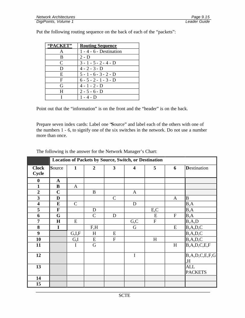
Put the following routing sequence on the back of each of the “packets”:
“PACKET” Routing Sequence
A 1 - 4 - 6 - Destination B 2 - D C 3 - 1 - 5 - 2 - 4 - D D 4 - 2 - 3 - D E 5 - 1 - 6 - 3 - 2 - D F 6 - 5 - 2 - 1 - 3 - D G 4 - 1 - 2 - D H 2 - 5 - 6 - D I 1 - 4 - D
Point out that the “information” is on the front and the “header” is on the back.
Prepare seven index cards: Label one “Source” and label each of the others with one of the numbers 1 - 6, to signify one of the six switches in the network. Do not use a number more than once.
The following is the answer for the Network Manager’s Chart:
Location of Packets by Source, Switch, or Destination
Clock Cycle
Source 1 2 3 4 5 6 Destination
0 A 1 B A 2 C B A 3 D C A B 4 E C D B,A 5 F D E,C B,A 6 G C D E F B,A 7 H E G,C F B,A,D 8 I F,H G E B,A,D,C 9 G,I,F H E B,A,D,C 10 G,I E F H B,A,D,C 11 I G H B,A,D,C,E,F
12 I B,A,D,C,E,F,G,H
13 ALL PACKETS
14 15
Network Architectures Page 9.16 DigiPoints, Volume 1 Leader Guide
SCTE
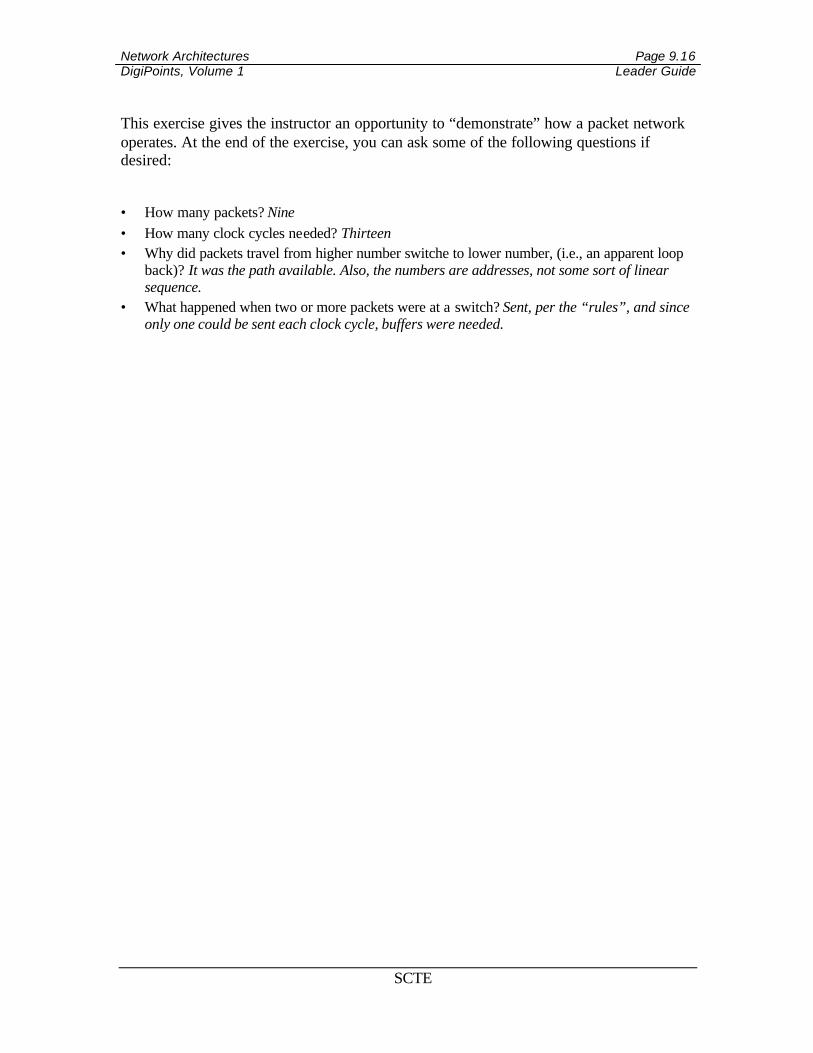
This exercise gives the instructor an opportunity to “demonstrate” how a packet network operates. At the end of the exercise, you can ask some of the following questions if desired:
• How many packets? Nine • How many clock cycles needed? Thirteen • Why did packets travel from higher number switche to lower number, (i.e., an apparent loop
back)? It was the path available. Also, the numbers are addresses, not some sort of linear sequence.
• What happened when two or more packets were at a switch? Sent, per the “rules”, and since only one could be sent each clock cycle, buffers were needed.
Network Architectures Page 9.17 DigiPoints, Volume 1 Leader Guide
SCTE
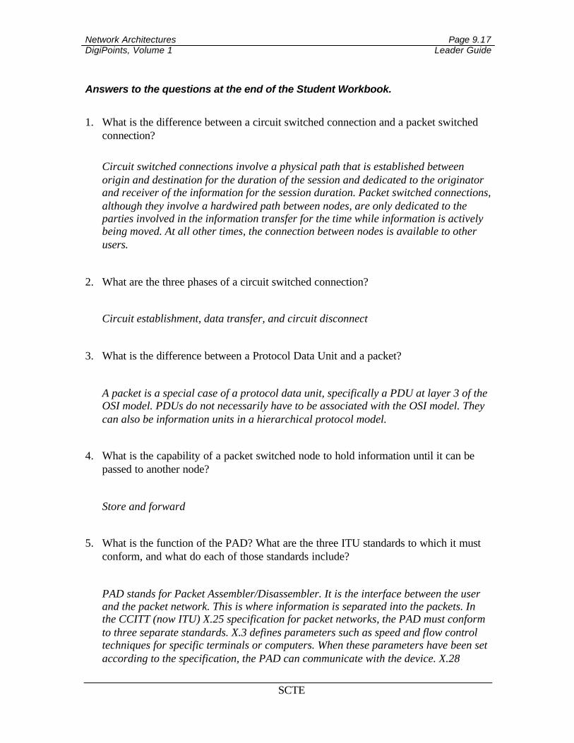
Answers to the questions at the end of the Student Workbook.
1. What is the difference between a circuit switched connection and a packet switched connection?
Circuit switched connections involve a physical path that is established between origin and destination for the duration of the session and dedicated to the originator and receiver of the information for the session duration. Packet switched connections, although they involve a hardwired path between nodes, are only dedicated to the parties involved in the information transfer for the time while information is actively being moved. At all other times, the connection between nodes is available to other users.
2. What are the three phases of a circuit switched connection?
Circuit establishment, data transfer, and circuit disconnect
3. What is the difference between a Protocol Data Unit and a packet?
A packet is a special case of a protocol data unit, specifically a PDU at layer 3 of the OSI model. PDUs do not necessarily have to be associated with the OSI model. They can also be information units in a hierarchical protocol model.
4. What is the capability of a packet switched node to hold information until it can be passed to another node?
Store and forward
5. What is the function of the PAD? What are the three ITU standards to which it must conform, and what do each of those standards include?
PAD stands for Packet Assembler/Disassembler. It is the interface between the user and the packet network. This is where information is separated into the packets. In the CCITT (now ITU) X.25 specification for packet networks, the PAD must conform to three separate standards. X.3 defines parameters such as speed and flow control techniques for specific terminals or computers. When these parameters have been set according to the specification, the PAD can communicate with the device. X.28
Network Architectures Page 9.18 DigiPoints, Volume 1 Leader Guide
SCTE
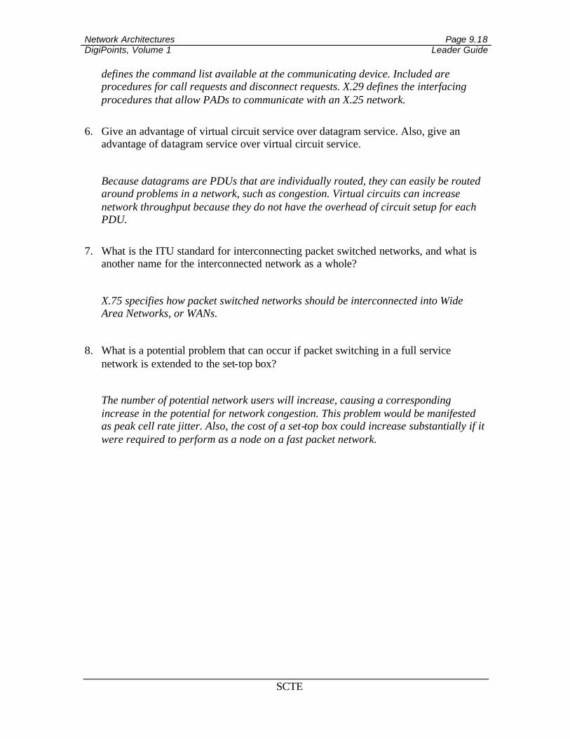
defines the command list available at the communicating device. Included are procedures for call requests and disconnect requests. X.29 defines the interfacing procedures that allow PADs to communicate with an X.25 network.
6. Give an advantage of virtual circuit service over datagram service. Also, give an
advantage of datagram service over virtual circuit service.
Because datagrams are PDUs that are individually routed, they can easily be routed around problems in a network, such as congestion. Virtual circuits can increase network throughput because they do not have the overhead of circuit setup for each PDU.
7. What is the ITU standard for interconnecting packet switched networks, and what is
another name for the interconnected network as a whole?
X.75 specifies how packet switched networks should be interconnected into Wide Area Networks, or WANs.
8. What is a potential problem that can occur if packet switching in a full service network is extended to the set-top box?
The number of potential network users will increase, causing a corresponding increase in the potential for network congestion. This problem would be manifested as peak cell rate jitter. Also, the cost of a set-top box could increase substantially if it were required to perform as a node on a fast packet network.