Embed Size (px)
DESCRIPTION
machanical
Citation preview
SENR3130-09July 2003
SpecificationsTorque Specifications
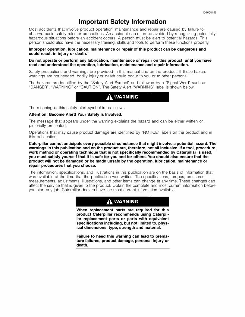
i01658146
Important Safety InformationMost accidents that involve product operation, maintenance and repair are caused by failure toobserve basic safety rules or precautions. An accident can often be avoided by recognizing potentiallyhazardous situations before an accident occurs. A person must be alert to potential hazards. Thisperson should also have the necessary training, skills and tools to perform these functions properly.
Improper operation, lubrication, maintenance or repair of this product can be dangerous andcould result in injury or death.
Do not operate or perform any lubrication, maintenance or repair on this product, until you haveread and understood the operation, lubrication, maintenance and repair information.
Safety precautions and warnings are provided in this manual and on the product. If these hazardwarnings are not heeded, bodily injury or death could occur to you or to other persons.
The hazards are identified by the “Safety Alert Symbol” and followed by a “Signal Word” such as“DANGER”, “WARNING” or “CAUTION”. The Safety Alert “WARNING” label is shown below.
The meaning of this safety alert symbol is as follows:
Attention! Become Alert! Your Safety is Involved.
The message that appears under the warning explains the hazard and can be either written orpictorially presented.
Operations that may cause product damage are identified by “NOTICE” labels on the product and inthis publication.
Caterpillar cannot anticipate every possible circumstance that might involve a potential hazard. Thewarnings in this publication and on the product are, therefore, not all inclusive. If a tool, procedure,work method or operating technique that is not specifically recommended by Caterpillar is used,you must satisfy yourself that it is safe for you and for others. You should also ensure that theproduct will not be damaged or be made unsafe by the operation, lubrication, maintenance orrepair procedures that you choose.
The information, specifications, and illustrations in this publication are on the basis of information thatwas available at the time that the publication was written. The specifications, torques, pressures,measurements, adjustments, illustrations, and other items can change at any time. These changes canaffect the service that is given to the product. Obtain the complete and most current information beforeyou start any job. Caterpillar dealers have the most current information available.
When replacement parts are required for thisproduct Caterpillar recommends using Caterpil-lar replacement parts or parts with equivalentspecifications including, but not limited to, phys-ical dimensions, type, strength and material.
Failure to heed this warning can lead to prema-ture failures, product damage, personal injury ordeath.

3Table of Contents
Table of Contents
Specifications Section
General Information .............................................. 4Metric (ISO) Fasteners .......................................... 4English (SAE) Fasteners ....................................... 5Ground Engaging Tool (G.E.T.) Fasteners ............ 6Installation of Fittings ............................................ 7Straight Thread O-Ring Fittings ............................ 8Plugs ..................................................................... 9O-Ring Face Seal Fittings ..................................... 11Bulkhead Nuts ...................................................... 11Flare Fittings ......................................................... 12Air Conditioning Fittings ........................................ 13Air Brake Fittings ................................................... 13Tapered Pipe Thread Fittings ................................ 14Miscellaneous Fittings .......................................... 14Hose Clamps ........................................................ 15
Index Section
Index ..................................................................... 17
4Specifications Section
Specifications Section
i01773016
General InformationSMCS Code: 7553
Mismatched or incorrect fasteners can result indamage or malfunction, or personal injury.
Take care to avoid mixing metric dimensioned fas-teners and inch dimensioned fasteners.
Exceptions to these torques are given in the ServiceManual, if necessary.
Torque wrenches must be used properly in order toensure that the correct torque is applied. Alwaysuse a smooth pull for torque wrenches. Do not jerka torque wrench. For the correct use of your torquewrench, refer to the instructions that were packagedwith your torque wrench. For more information onthe correct use of torque wrenches, refer to SpecialPublication, SEBV0516, “An Introduction to Torque”.
Be sure to use a torque wrench that has the properrange. Torque values are given in the followingunits:NEWTON meters (N·m), pound feet (lb ft), andpound inches (lb in)
Prior to installation of any hardware, ensure thatcomponents are in near new condition. Bolts andthreads must not be worn or damaged. Threadsmust not have burrs or nicks. Hardware must befree of rust and corrosion. Clean reused fastenerswith a noncorrosive cleaner. Lightly lubricate thethreads of reused fasteners. Lightly lubricate themating surface of the head of reused fasteners.Other applications for lubricating fasteners may alsobe specified in the Service Manual. The ServiceManual may also specify the use of sealants andcompounds.
i01938156
Metric (ISO) FastenersSMCS Code: 7553
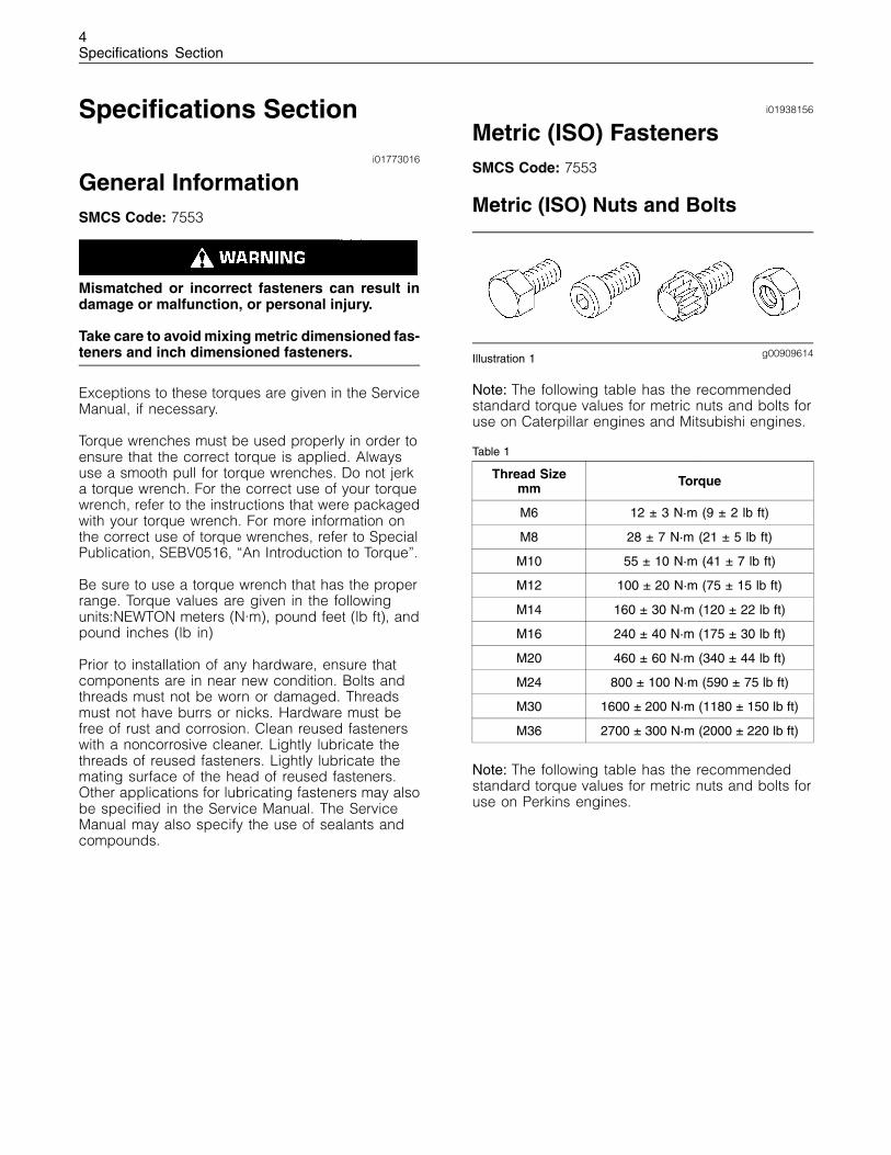
Metric (ISO) Nuts and Bolts
g00909614Illustration 1
Note: The following table has the recommendedstandard torque values for metric nuts and bolts foruse on Caterpillar engines and Mitsubishi engines.
Table 1
Thread Sizemm Torque
M6 12 ± 3 N·m (9 ± 2 lb ft)
M8 28 ± 7 N·m (21 ± 5 lb ft)
M10 55 ± 10 N·m (41 ± 7 lb ft)
M12 100 ± 20 N·m (75 ± 15 lb ft)
M14 160 ± 30 N·m (120 ± 22 lb ft)
M16 240 ± 40 N·m (175 ± 30 lb ft)
M20 460 ± 60 N·m (340 ± 44 lb ft)
M24 800 ± 100 N·m (590 ± 75 lb ft)
M30 1600 ± 200 N·m (1180 ± 150 lb ft)
M36 2700 ± 300 N·m (2000 ± 220 lb ft)
Note: The following table has the recommendedstandard torque values for metric nuts and bolts foruse on Perkins engines.
5Specifications Section
Table 2
Thread Sizemm Torque
M6 5 N·m (44 lb in)
M8 22 N·m (16 lb ft)
M10 44 N·m (32 lb ft)
M12 78 N·m (58 lb ft)
M14 124 N·m (91 lb ft)
M16 177 N·m (131 lb ft)
M18 200 N·m (148 lb ft)
M20 400 N·m (295 lb ft)
M24 790 N·m (582 lb ft)
Note: The difference between Caterpillar standardtorque values and Perkins standard torque valuesare due to different grade of bolts and fasteners.Caterpillar uses grade 8 bolts and fasteners. Perkinsuses grade 5 bolts and fasteners.
Metric (ISO) Taperlock Studs
Note: The following table has the recommendedstandard torque values for metric taperlock studs foruse on Caterpillar engines and Mitsubishi engines.
Table 3
Thread Sizemm Torque
M6 8 ± 3 N·m (71 ± 27 lb in)
M8 17 ± 5 N·m (13 ± 4 lb ft)
M10 35 ± 5 N·m (26 ± 4 lb ft)
M12 65 ± 10 N·m (48 ± 7 lb ft)
M16 110 ± 20 N·m (80 ± 15 lb ft)
M20 170 ± 30 N·m (125 ± 22 lb ft)
M24 400 ± 60 N·m (300 ± 44 lb ft)
M30 750 ± 80 N·m (550 ± 60 lb ft)
M36 1200 ± 150 N·m (880 ± 110 lb ft)
Note: The following table has the recommendedstandard torque values for Metric taperlock studsfor use on Perkins engines.
Table 4
Thread Sizemm Torque
M6 5 N·m (44 lb in)
M8 11 N·m (97 lb in)
M10 18 N·m (13 lb ft)
M12 25 N·m (18 lb ft)
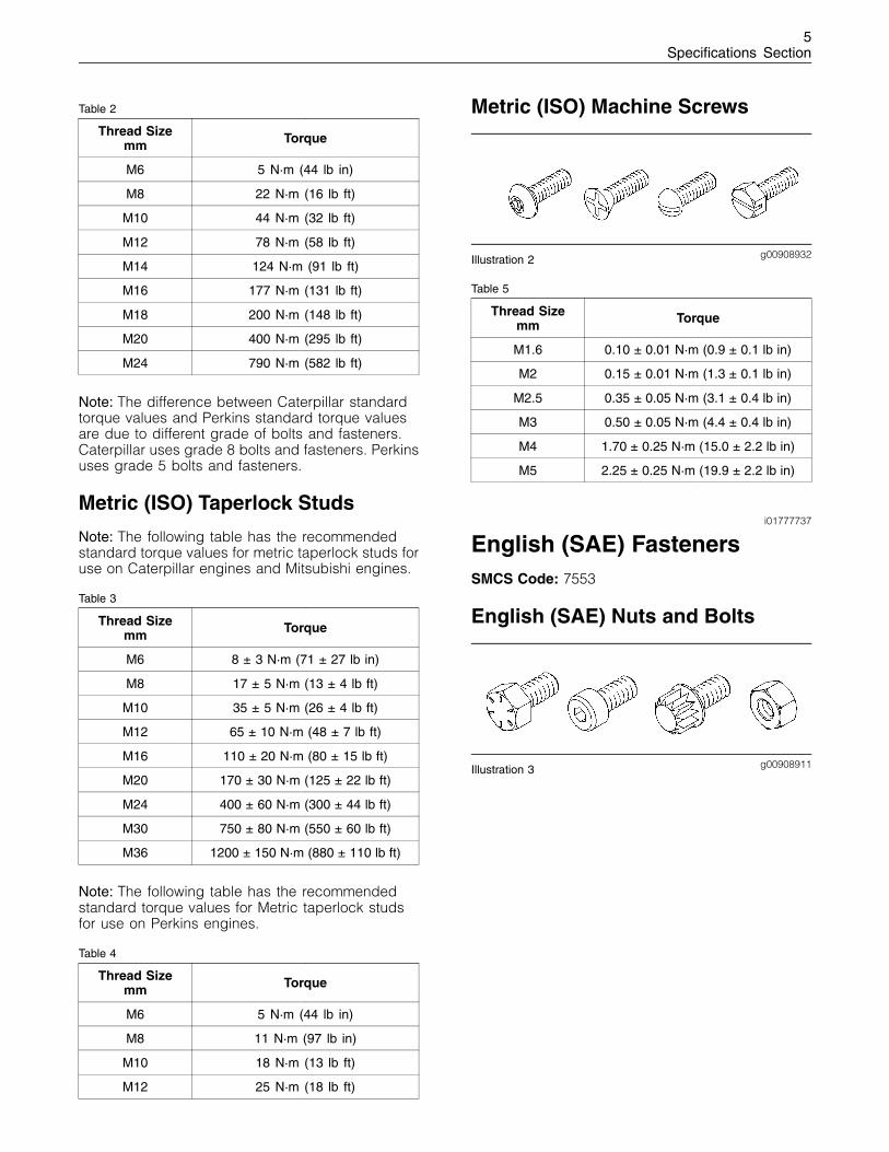
Metric (ISO) Machine Screws
g00908932Illustration 2
Table 5
Thread Sizemm Torque
M1.6 0.10 ± 0.01 N·m (0.9 ± 0.1 lb in)
M2 0.15 ± 0.01 N·m (1.3 ± 0.1 lb in)
M2.5 0.35 ± 0.05 N·m (3.1 ± 0.4 lb in)
M3 0.50 ± 0.05 N·m (4.4 ± 0.4 lb in)
M4 1.70 ± 0.25 N·m (15.0 ± 2.2 lb in)
M5 2.25 ± 0.25 N·m (19.9 ± 2.2 lb in)
i01777737
English (SAE) FastenersSMCS Code: 7553
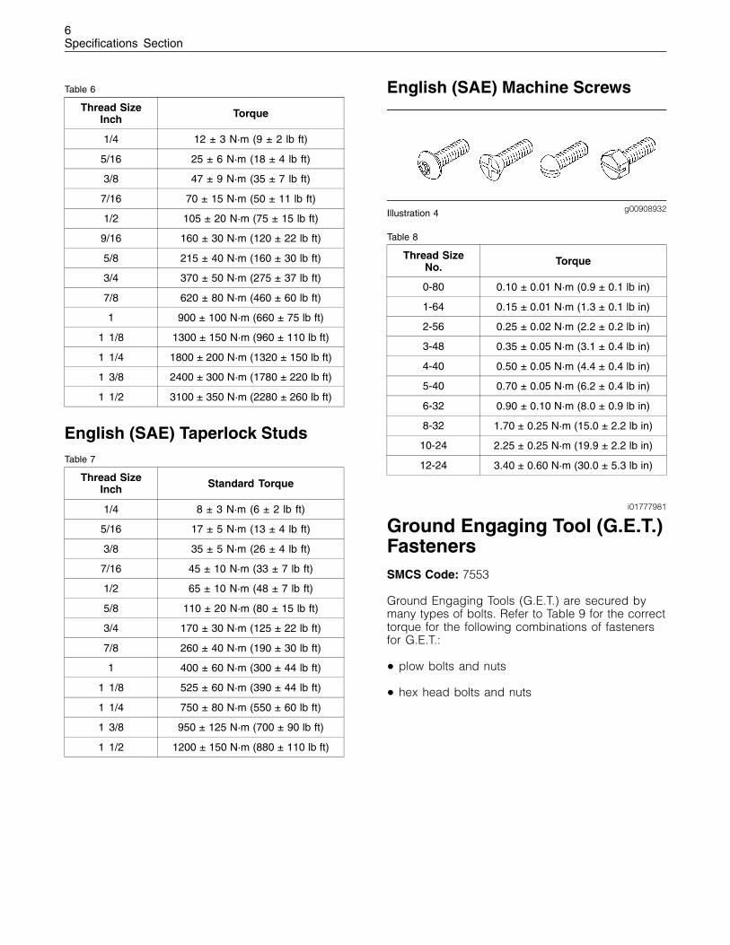
English (SAE) Nuts and Bolts
g00908911Illustration 3
6Specifications Section
Table 6
Thread SizeInch Torque
1/4 12 ± 3 N·m (9 ± 2 lb ft)
5/16 25 ± 6 N·m (18 ± 4 lb ft)
3/8 47 ± 9 N·m (35 ± 7 lb ft)
7/16 70 ± 15 N·m (50 ± 11 lb ft)
1/2 105 ± 20 N·m (75 ± 15 lb ft)
9/16 160 ± 30 N·m (120 ± 22 lb ft)
5/8 215 ± 40 N·m (160 ± 30 lb ft)
3/4 370 ± 50 N·m (275 ± 37 lb ft)
7/8 620 ± 80 N·m (460 ± 60 lb ft)
1 900 ± 100 N·m (660 ± 75 lb ft)
1 1/8 1300 ± 150 N·m (960 ± 110 lb ft)
1 1/4 1800 ± 200 N·m (1320 ± 150 lb ft)
1 3/8 2400 ± 300 N·m (1780 ± 220 lb ft)
1 1/2 3100 ± 350 N·m (2280 ± 260 lb ft)
English (SAE) Taperlock StudsTable 7
Thread SizeInch Standard Torque
1/4 8 ± 3 N·m (6 ± 2 lb ft)
5/16 17 ± 5 N·m (13 ± 4 lb ft)
3/8 35 ± 5 N·m (26 ± 4 lb ft)
7/16 45 ± 10 N·m (33 ± 7 lb ft)
1/2 65 ± 10 N·m (48 ± 7 lb ft)
5/8 110 ± 20 N·m (80 ± 15 lb ft)
3/4 170 ± 30 N·m (125 ± 22 lb ft)
7/8 260 ± 40 N·m (190 ± 30 lb ft)
1 400 ± 60 N·m (300 ± 44 lb ft)
1 1/8 525 ± 60 N·m (390 ± 44 lb ft)
1 1/4 750 ± 80 N·m (550 ± 60 lb ft)
1 3/8 950 ± 125 N·m (700 ± 90 lb ft)
1 1/2 1200 ± 150 N·m (880 ± 110 lb ft)
English (SAE) Machine Screws
g00908932Illustration 4
Table 8
Thread SizeNo. Torque
0-80 0.10 ± 0.01 N·m (0.9 ± 0.1 lb in)
1-64 0.15 ± 0.01 N·m (1.3 ± 0.1 lb in)
2-56 0.25 ± 0.02 N·m (2.2 ± 0.2 lb in)
3-48 0.35 ± 0.05 N·m (3.1 ± 0.4 lb in)
4-40 0.50 ± 0.05 N·m (4.4 ± 0.4 lb in)
5-40 0.70 ± 0.05 N·m (6.2 ± 0.4 lb in)
6-32 0.90 ± 0.10 N·m (8.0 ± 0.9 lb in)
8-32 1.70 ± 0.25 N·m (15.0 ± 2.2 lb in)
10-24 2.25 ± 0.25 N·m (19.9 ± 2.2 lb in)
12-24 3.40 ± 0.60 N·m (30.0 ± 5.3 lb in)
i01777981
Ground Engaging Tool (G.E.T.)FastenersSMCS Code: 7553
Ground Engaging Tools (G.E.T.) are secured bymany types of bolts. Refer to Table 9 for the correcttorque for the following combinations of fastenersfor G.E.T.:
• plow bolts and nuts
• hex head bolts and nuts
7Specifications Section
Table 9
Torque(1)Thread SizeInch N·m lb ft
5/8 inch 270 ± 40 200 ± 30
3/4 inch 475 ± 60 350 ± 45
7/8 inch 750 ± 90 550 ± 65
1 inch 1150 ± 150 850 ± 110
1 1/4 inch 2300 ± 300 1700 ± 220
(1) These values are only for Caterpillar bolts for cutting edges.
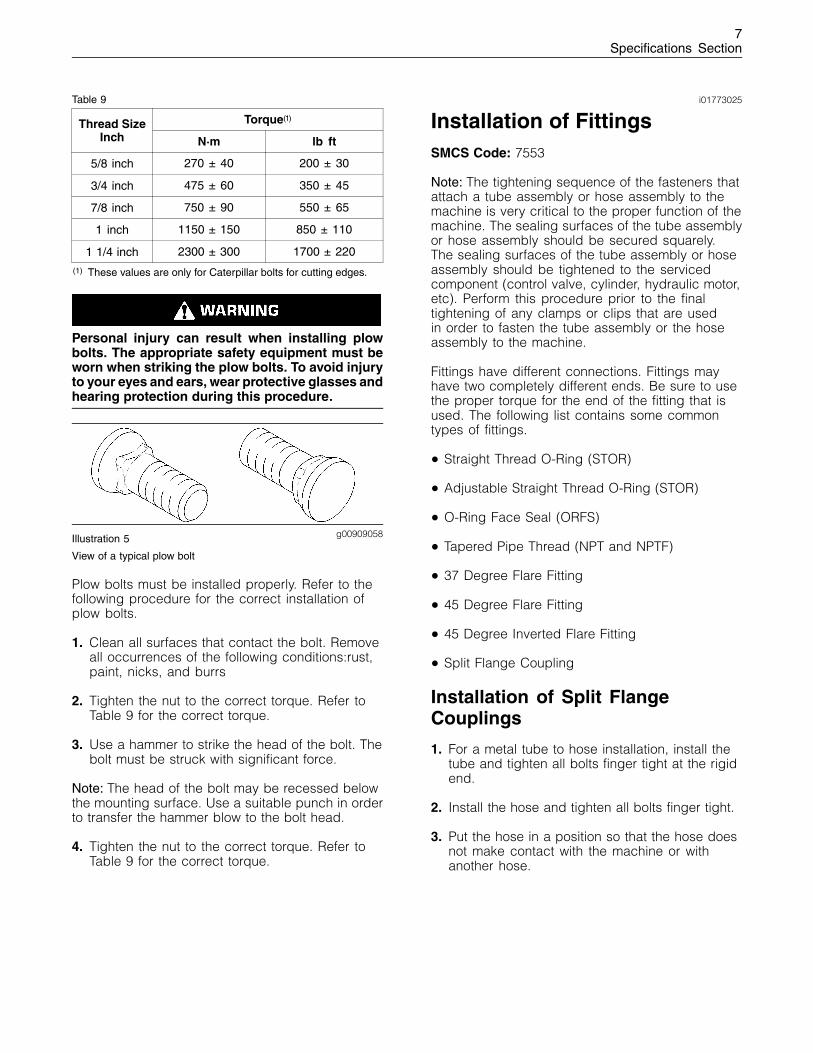
Personal injury can result when installing plowbolts. The appropriate safety equipment must beworn when striking the plow bolts. To avoid injuryto your eyes and ears, wear protective glasses andhearing protection during this procedure.
g00909058Illustration 5
View of a typical plow bolt
Plow bolts must be installed properly. Refer to thefollowing procedure for the correct installation ofplow bolts.
1. Clean all surfaces that contact the bolt. Removeall occurrences of the following conditions:rust,paint, nicks, and burrs
2. Tighten the nut to the correct torque. Refer toTable 9 for the correct torque.
3. Use a hammer to strike the head of the bolt. Thebolt must be struck with significant force.
Note: The head of the bolt may be recessed belowthe mounting surface. Use a suitable punch in orderto transfer the hammer blow to the bolt head.
4. Tighten the nut to the correct torque. Refer toTable 9 for the correct torque.
i01773025
Installation of FittingsSMCS Code: 7553
Note: The tightening sequence of the fasteners thatattach a tube assembly or hose assembly to themachine is very critical to the proper function of themachine. The sealing surfaces of the tube assemblyor hose assembly should be secured squarely.The sealing surfaces of the tube assembly or hoseassembly should be tightened to the servicedcomponent (control valve, cylinder, hydraulic motor,etc). Perform this procedure prior to the finaltightening of any clamps or clips that are usedin order to fasten the tube assembly or the hoseassembly to the machine.
Fittings have different connections. Fittings mayhave two completely different ends. Be sure to usethe proper torque for the end of the fitting that isused. The following list contains some commontypes of fittings.
• Straight Thread O-Ring (STOR)
• Adjustable Straight Thread O-Ring (STOR)
• O-Ring Face Seal (ORFS)
• Tapered Pipe Thread (NPT and NPTF)
• 37 Degree Flare Fitting
• 45 Degree Flare Fitting
• 45 Degree Inverted Flare Fitting
• Split Flange Coupling
Installation of Split FlangeCouplings
1. For a metal tube to hose installation, install thetube and tighten all bolts finger tight at the rigidend.
2. Install the hose and tighten all bolts finger tight.
3. Put the hose in a position so that the hose doesnot make contact with the machine or withanother hose.
8Specifications Section
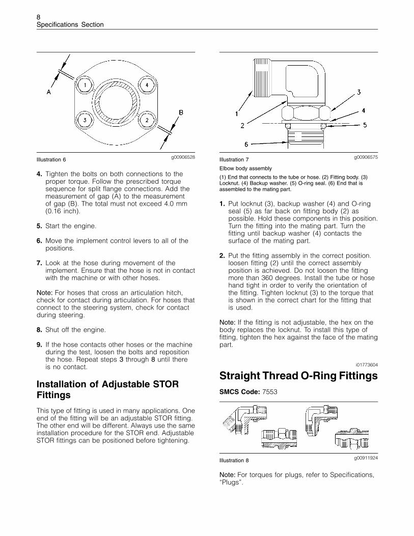
g00906528Illustration 6
4. Tighten the bolts on both connections to theproper torque. Follow the prescribed torquesequence for split flange connections. Add themeasurement of gap (A) to the measurementof gap (B). The total must not exceed 4.0 mm(0.16 inch).
5. Start the engine.
6. Move the implement control levers to all of thepositions.
7. Look at the hose during movement of theimplement. Ensure that the hose is not in contactwith the machine or with other hoses.
Note: For hoses that cross an articulation hitch,check for contact during articulation. For hoses thatconnect to the steering system, check for contactduring steering.
8. Shut off the engine.
9. If the hose contacts other hoses or the machineduring the test, loosen the bolts and repositionthe hose. Repeat steps 3 through 8 until thereis no contact.
Installation of Adjustable STORFittings
This type of fitting is used in many applications. Oneend of the fitting will be an adjustable STOR fitting.The other end will be different. Always use the sameinstallation procedure for the STOR end. AdjustableSTOR fittings can be positioned before tightening.
g00906575Illustration 7
Elbow body assembly
(1) End that connects to the tube or hose. (2) Fitting body. (3)Locknut. (4) Backup washer. (5) O-ring seal. (6) End that isassembled to the mating part.
1. Put locknut (3), backup washer (4) and O-ringseal (5) as far back on fitting body (2) aspossible. Hold these components in this position.Turn the fitting into the mating part. Turn thefitting until backup washer (4) contacts thesurface of the mating part.
2. Put the fitting assembly in the correct position.loosen fitting (2) until the correct assemblyposition is achieved. Do not loosen the fittingmore than 360 degrees. Install the tube or hosehand tight in order to verify the orientation ofthe fitting. Tighten locknut (3) to the torque thatis shown in the correct chart for the fitting thatis used.
Note: If the fitting is not adjustable, the hex on thebody replaces the locknut. To install this type offitting, tighten the hex against the face of the matingpart.
i01773604
Straight Thread O-Ring FittingsSMCS Code: 7553
g00911924Illustration 8
Note: For torques for plugs, refer to Specifications,“Plugs”.
9Specifications Section
Table 10
Ferrous Straight Thread O-Ring FittingTorques for Mating with Ferrous Materials
Nominal OuterDiameter of
the Tube
Thread SizeInch
StandardTorque
3.18 mm(.125 inch) 5/16 - 24 8.0 ± 1.0 N·m
(70 ± 9 lb in)
4.76 mm(.188 inch) 3/8 - 24 12 ± 2 N·m
(9 ± 1 lb ft)
6.35 mm(.250 inch) 7/16 - 20 22 ± 2 N·m
(16 ± 1 lb ft)
7.94 mm(.312 inch) 1/2 - 20 30 ± 3 N·m
(22 ± 2 lb ft)
9.52 mm(.375 inch) 9/16 - 18 48 ± 5 N·m
(35 ± 4 lb ft)
12.70 mm(.500 inch) 3/4 - 16 82 ± 8 N·m
(60 ± 6 lb ft)
15.88 mm(.625 inch) 7/8 - 14 140 ± 14 N·m
(105 ± 10 lb ft)
19.05 mm(.750 inch) 1 1/16 - 12 190 ± 15 N·m
(140 ± 11 lb ft)
22.22 mm(.875 inch) 1 3/16 - 12 250 ± 20 N·m
(185 ± 15 lb ft)
25.40 mm(1.000 inch) 1 5/16 - 12 300 ± 30 N·m
(220 ± 22 lb ft)
31.75 mm(1.250 inch) 1 5/8 - 12 350 ± 35 N·m
(260 ± 26 lb ft)
38.10 mm(1.500 inch) 1 7/8 - 12 415 ± 40 N·m
(305 ± 30 lb ft)
50.80 mm(2.000 inch) 2 1/2 - 12 430 ± 40 N·m
(320 ± 30 lb ft)
Note: Use 50 percent of the torque values fromTable 10 when the fitting or the port material isnonferrous.
i01782872
PlugsSMCS Code: 7553
Straight Thread O-Ring Plugs (HexDrive)
g00911999Illustration 9
Table 11
Thread SizeInch
Torque
5/16 9.0 ± 1.0 N·m (80 ± 9 lb in)
3/8 17.0 ± 1.5 N·m (12.5 ± 1.1 lb ft)
7/16 23 ± 2 N·m (17 ± 1 lb ft)
1/2 28 ± 3 N·m (21 ± 2 lb ft)
9/16 34 ± 3 N·m (25 ± 2 lb ft)
3/4 60 ± 6 N·m (44 ± 4 lb ft)
7/8 115 ± 10 N·m (85 ± 7 lb ft)
1 1/16 140 ± 14 N·m (103 ± 10 lb ft)
1 3/16 190 ± 19 N·m (140 ± 14 lb ft)
1 5/16 210 ± 20 N·m (155 ± 15 lb ft)
1 5/8 290 ± 25 N·m (215 ± 18 lb ft)
1 7/8 325 ± 30 N·m (240 ± 22 lb ft)
2 1/2 420 ± 40 N·m (310 ± 30 lb ft)
Straight Thread O-Ring Plugs(Socket Drive)
g00912006Illustration 10
Note: The socket may be hexagonal or square.
10Specifications Section
Table 12
Thread SizeInch
Torque
5/16 5.0 ± 1.0 N·m (44 ± 9 lb in)
3/8 11.0 ± 1.0 N·m (97 ± 9 lb in)
7/16 16.0 ± 1.5 N·m (12 ± 1 lb ft)
1/2 20 ± 2 N·m (15 ± 1 lb ft)
9/16 35.0 ± 3.5 N·m (26 ± 3 lb ft)
3/4 70 ± 7 N·m (52 ± 5 lb ft)
7/8 100 ± 10 N·m (73 ± 7 lb ft)
1 1/16 170 ± 15 N·m (125 ± 11 lb ft)
1 3/16 215 ± 20 N·m (160 ± 15 lb ft)
1 5/16 270 ± 25 N·m (200 ± 18 lb ft)
1 5/8 285 ± 25 N·m (2105 ± 185 lb ft)
1 7/8 370 ± 35 N·m (275 ± 255 lb ft)
2 1/2 415 ± 40 N·m (305 ± 30 lb ft)
Drain Plugs with Straight Threads
g00912008Illustration 11
Note: Plug (A), plug (B) and plug (C) are usedwith a gasket. Conical seal plug (D) does not usea gasket.
Table 13
Type ofPlug
Thread SizeInch
Torque
1/2 - 13 20 ± 5 N·m (15 ± 4 lb ft)
5/8 - 11 35 ± 5 N·m (26 ± 4 lb ft)
3/4 - 123/4 - 16
50 ± 5 N·m (37 ± 4 lb ft)A
7/8 - 141 1/8 - 12
70 ± 15 N·m (52 ± 11 lb ft)
1 5/16 - 121 1/2 - 12
90 ± 15 N·m (66 ± 11 lb ft)
B
2 - 12 125 ± 15 N·m (92 ± 11 lb ft)
1 1/8 - 12 70 ± 15 N·m (52 ± 11 lb ft)C
1 5/16 - 12 90 ± 15 N·m (66 ± 11 lb ft)
1/2 - 20 11 ± 4 N·m (97 ± 35 lb in)
7/8 -14 55 ± 7 N·m (41 ± 5 lb ft)
1 3/8 -13 90 ± 15 N·m (66 ± 11 lb ft)D
1 1/2 - 12 125 ± 15 N·m (92 ± 11 lb ft)
Straight Thread O-RingPlugs (Mechanical Joint TubeAssemblies)
g00912010Illustration 12
Note: When you tighten the plug, the torque mustnot be transmitted to the joint between the tube andthe elbow.
11Specifications Section
Table 14
Thread SizeInch
Torque
7/8 125 ± 15 N·m (92 ± 11 lb ft)
1 1/16 175 ± 15 N·m (130 ± 11 lb ft)
1 3/16 250 ± 20 N·m (185 ± 15 lb ft)
1 1/4 250 ± 20 N·m (185 ± 15 lb ft)
1 5/16 370 ± 20 N·m (275 ± 15 lb ft)
1 5/8 420 ± 25 N·m (310 ± 20 lb ft)
1 7/8 525 ± 35 N·m (390 ± 25 lb ft)
2 1/2 900 ± 50 N·m (665 ± 40 lb ft)
i01772857
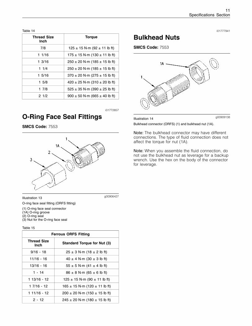
O-Ring Face Seal FittingsSMCS Code: 7553
g00906427Illustration 13
O-ring face seal fitting (ORFS fitting)
(1) O-ring face seal connector(1A) O-ring groove(2) O-ring seal(3) Nut for the O-ring face seal
Table 15
Ferrous ORFS Fitting
Thread SizeInch Standard Torque for Nut (3)
9/16 - 18 25 ± 3 N·m (18 ± 2 lb ft)
11/16 - 16 40 ± 4 N·m (30 ± 3 lb ft)
13/16 - 16 55 ± 5 N·m (41 ± 4 lb ft)
1 - 14 86 ± 8 N·m (65 ± 6 lb ft)
1 13/16 - 12 125 ± 15 N·m (90 ± 11 lb ft)
1 7/16 - 12 165 ± 15 N·m (120 ± 11 lb ft)
1 11/16 - 12 200 ± 20 N·m (150 ± 15 lb ft)
2 - 12 245 ± 20 N·m (180 ± 15 lb ft)
i01777941
Bulkhead NutsSMCS Code: 7553
g00909138Illustration 14
Bulkhead connector (ORFS) (1) and bulkhead nut (1A).
Note: The bulkhead connector may have differentconnections. The type of fluid connection does notaffect the torque for nut (1A).
Note: When you assemble the fluid connection, donot use the bulkhead nut as leverage for a backupwrench. Use the hex on the body of the connectorfor leverage.
12Specifications Section
Table 16
Thread SizeInch
Torque
5/16 6 ± 1 N·m (53 ± 9 lb in)
3/8 8 ± 1 N·m (71 ± 9 lb in)
7/16 14 ± 1.5 N·m (10 ± 1 lb ft)
1/2 17 ± 2 N·m (13 ± 1.4 lb ft)
9/16 22 ± 2 N·m (16 ± 1.4 lb ft)
11/16 31 ± 3 N·m (23 ± 2 lb ft)
3/4 37 ± 4 N·m (27 ± 3 lb ft)
13/16 40 ± 4 N·m (30 ± 3 lb ft)
7/8 44 ± 4 N·m (32 ± 3 lb ft)
1 61 ± 6 N·m (45 ± 4 lb ft)
1 1/16 70 ± 7 N·m (52 ± 5 lb ft)
1 3/16 91 ± 10 N·m (67 ± 7 lb ft)
1 5/16 113 ± 10 N·m (83 ± 7 lb ft)
1 7/16 125 ± 12 N·m (92 ± 9 lb ft)
1 5/8 150 ± 15 N·m (110 ± 11 lb ft)
1 11/16 150 ± 15 N·m (110 ± 11 lb ft)
1 7/8 155 ± 15 N·m (115 ± 11 lb ft)
2 170 ± 17 N·m (125 ± 13 lb ft)
2 1/2 220 ± 20 N·m (160 ± 15 lb ft)
i01773459
Flare FittingsSMCS Code: 7553
The torques in Table 17 are for 37 degree flarefittings. The torques in Table 18 are for 45 degreeflare fittings and 45 degree inverted flare fittings.
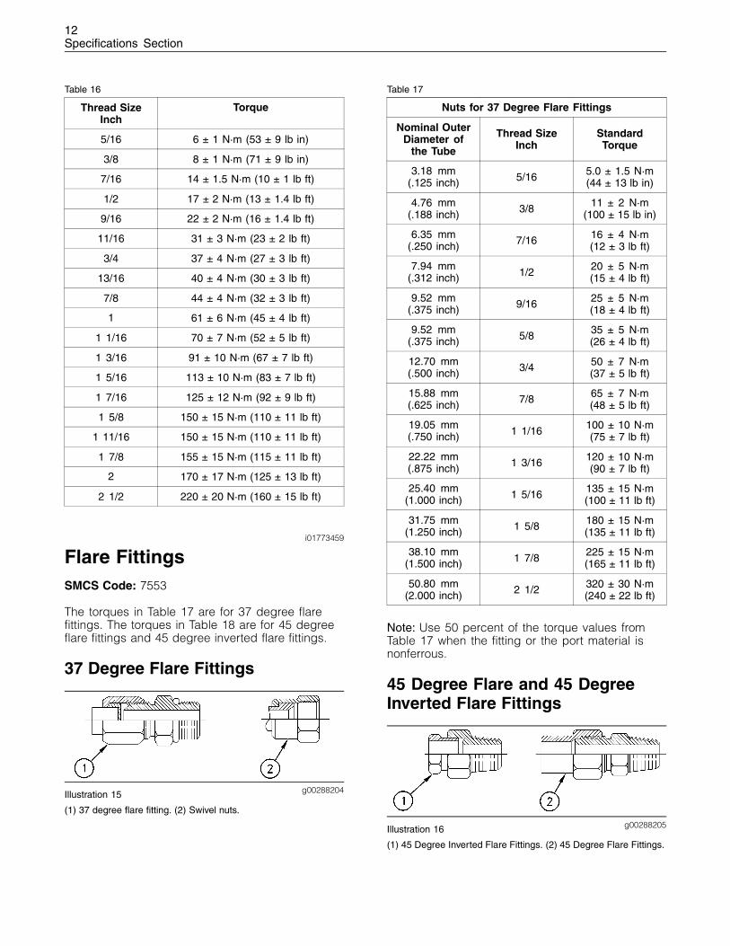
37 Degree Flare Fittings
g00288204Illustration 15
(1) 37 degree flare fitting. (2) Swivel nuts.
Table 17
Nuts for 37 Degree Flare Fittings
Nominal OuterDiameter of
the Tube
Thread SizeInch
StandardTorque
3.18 mm(.125 inch) 5/16 5.0 ± 1.5 N·m
(44 ± 13 lb in)
4.76 mm(.188 inch) 3/8 11 ± 2 N·m
(100 ± 15 lb in)
6.35 mm(.250 inch) 7/16 16 ± 4 N·m
(12 ± 3 lb ft)
7.94 mm(.312 inch) 1/2 20 ± 5 N·m
(15 ± 4 lb ft)
9.52 mm(.375 inch) 9/16 25 ± 5 N·m
(18 ± 4 lb ft)
9.52 mm(.375 inch) 5/8 35 ± 5 N·m
(26 ± 4 lb ft)
12.70 mm(.500 inch) 3/4 50 ± 7 N·m
(37 ± 5 lb ft)
15.88 mm(.625 inch) 7/8 65 ± 7 N·m
(48 ± 5 lb ft)
19.05 mm(.750 inch) 1 1/16 100 ± 10 N·m
(75 ± 7 lb ft)
22.22 mm(.875 inch) 1 3/16 120 ± 10 N·m
(90 ± 7 lb ft)
25.40 mm(1.000 inch) 1 5/16 135 ± 15 N·m
(100 ± 11 lb ft)
31.75 mm(1.250 inch) 1 5/8 180 ± 15 N·m
(135 ± 11 lb ft)
38.10 mm(1.500 inch) 1 7/8 225 ± 15 N·m
(165 ± 11 lb ft)
50.80 mm(2.000 inch) 2 1/2 320 ± 30 N·m
(240 ± 22 lb ft)
Note: Use 50 percent of the torque values fromTable 17 when the fitting or the port material isnonferrous.
45 Degree Flare and 45 DegreeInverted Flare Fittings
g00288205Illustration 16
(1) 45 Degree Inverted Flare Fittings. (2) 45 Degree Flare Fittings.
13Specifications Section
Table 18
45 Degree Flare Fittings and 45 DegreeInverted Flare Fittings
Nominal OuterDiameter of
the Tube
Thread SizeInch
StandardTorque
3.18 mm(.125 inch) 5/16 5.0 ± 1.5 N·m
(44 ± 13 lb in)
4.76 mm(.188 inch) 3/8 8.0 ± 1.5 N·m
(70 ± 13 lb in)
6.35 mm(.250 inch) 7/16 11 ± 2 N·m
(100 ± 15 lb in)
7.94 mm(.312 inch) 1/2 17 ± 3 N·m
(13 ± 2 lb ft)
9.52 mm(.375 inch) 5/8 30 ± 3 N·m
(22 ± 2 lb ft)
11.11 mm(.438 inch) 11/16 30 ± 3 N·m
(22 ± 2 lb ft)
12.70 mm(.500 inch) 3/4 38 ± 4 N·m
(28 ± 3 lb ft)
15.88 mm(.625 inch) 7/8 50 ± 5 N·m
(37 ± 4 lb ft)
19.05 mm(.750 inch) 1 1/16 90 ± 8 N·m
(65 ± 6 lb ft)
22.22 mm(.875 inch) 1 1/4 100 ± 10 N·m
(75 ± 7 lb ft)
i01773460
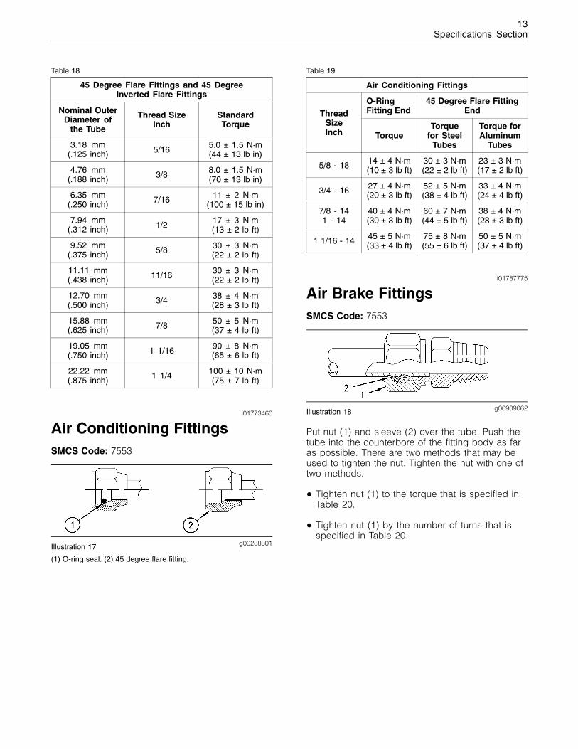
Air Conditioning FittingsSMCS Code: 7553
g00288301Illustration 17
(1) O-ring seal. (2) 45 degree flare fitting.
Table 19
Air Conditioning Fittings
O-RingFitting End
45 Degree Flare FittingEndThread
SizeInch Torque
Torquefor Steel
Tubes
Torque forAluminum
Tubes
5/8 - 18 14 ± 4 N·m(10 ± 3 lb ft)
30 ± 3 N·m(22 ± 2 lb ft)
23 ± 3 N·m(17 ± 2 lb ft)
3/4 - 16 27 ± 4 N·m(20 ± 3 lb ft)
52 ± 5 N·m(38 ± 4 lb ft)
33 ± 4 N·m(24 ± 4 lb ft)
7/8 - 141 - 14
40 ± 4 N·m(30 ± 3 lb ft)
60 ± 7 N·m(44 ± 5 lb ft)
38 ± 4 N·m(28 ± 3 lb ft)
1 1/16 - 14 45 ± 5 N·m(33 ± 4 lb ft)
75 ± 8 N·m(55 ± 6 lb ft)
50 ± 5 N·m(37 ± 4 lb ft)
i01787775
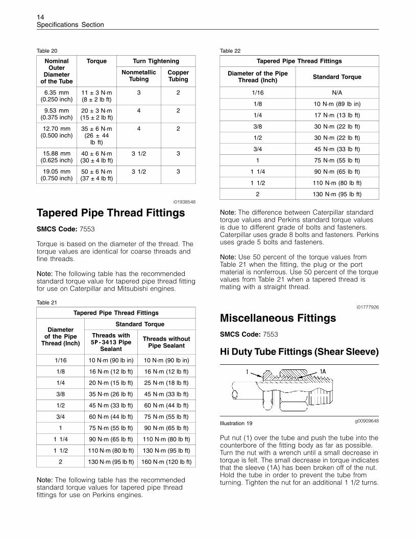
Air Brake FittingsSMCS Code: 7553
g00909062Illustration 18
Put nut (1) and sleeve (2) over the tube. Push thetube into the counterbore of the fitting body as faras possible. There are two methods that may beused to tighten the nut. Tighten the nut with one oftwo methods.
• Tighten nut (1) to the torque that is specified inTable 20.
• Tighten nut (1) by the number of turns that isspecified in Table 20.
14Specifications Section
Table 20
Turn TighteningNominalOuter
Diameterof the Tube
Torque
NonmetallicTubing
CopperTubing
6.35 mm(0.250 inch)
11 ± 3 N·m(8 ± 2 lb ft)
3 2
9.53 mm(0.375 inch)
20 ± 3 N·m(15 ± 2 lb ft)
4 2
12.70 mm(0.500 inch)
35 ± 6 N·m(26 ± 44
lb ft)
4 2
15.88 mm(0.625 inch)
40 ± 6 N·m(30 ± 4 lb ft)
3 1/2 3
19.05 mm(0.750 inch)
50 ± 6 N·m(37 ± 4 lb ft)
3 1/2 3
i01938548
Tapered Pipe Thread FittingsSMCS Code: 7553
Torque is based on the diameter of the thread. Thetorque values are identical for coarse threads andfine threads.
Note: The following table has the recommendedstandard torque value for tapered pipe thread fittingfor use on Caterpillar and Mitsubishi engines.
Table 21
Tapered Pipe Thread Fittings
Standard TorqueDiameter
of the PipeThread (Inch)
Threads with5P-3413 Pipe
Sealant
Threads withoutPipe Sealant
1/16 10 N·m (90 lb in) 10 N·m (90 lb in)
1/8 16 N·m (12 lb ft) 16 N·m (12 lb ft)
1/4 20 N·m (15 lb ft) 25 N·m (18 lb ft)
3/8 35 N·m (26 lb ft) 45 N·m (33 lb ft)
1/2 45 N·m (33 lb ft) 60 N·m (44 lb ft)
3/4 60 N·m (44 lb ft) 75 N·m (55 lb ft)
1 75 N·m (55 lb ft) 90 N·m (65 lb ft)
1 1/4 90 N·m (65 lb ft) 110 N·m (80 lb ft)
1 1/2 110 N·m (80 lb ft) 130 N·m (95 lb ft)
2 130 N·m (95 lb ft) 160 N·m (120 lb ft)
Note: The following table has the recommendedstandard torque values for tapered pipe threadfittings for use on Perkins engines.
Table 22
Tapered Pipe Thread Fittings
Diameter of the PipeThread (Inch) Standard Torque
1/16 N/A
1/8 10 N·m (89 lb in)
1/4 17 N·m (13 lb ft)
3/8 30 N·m (22 lb ft)
1/2 30 N·m (22 lb ft)
3/4 45 N·m (33 lb ft)
1 75 N·m (55 lb ft)
1 1/4 90 N·m (65 lb ft)
1 1/2 110 N·m (80 lb ft)
2 130 N·m (95 lb ft)
Note: The difference between Caterpillar standardtorque values and Perkins standard torque valuesis due to different grade of bolts and fasteners.Caterpillar uses grade 8 bolts and fasteners. Perkinsuses grade 5 bolts and fasteners.
Note: Use 50 percent of the torque values fromTable 21 when the fitting, the plug or the portmaterial is nonferrous. Use 50 percent of the torquevalues from Table 21 when a tapered thread ismating with a straight thread.
i01777926
Miscellaneous FittingsSMCS Code: 7553
Hi Duty Tube Fittings (Shear Sleeve)
g00909648Illustration 19
Put nut (1) over the tube and push the tube into thecounterbore of the fitting body as far as possible.Turn the nut with a wrench until a small decrease intorque is felt. The small decrease in torque indicatesthat the sleeve (1A) has been broken off of the nut.Hold the tube in order to prevent the tube fromturning. Tighten the nut for an additional 1 1/2 turns.
15Specifications Section
SAE Flareless Fittings
g00909647Illustration 20
Installing a New Flareless Fitting
Put nut (1) and sleeve (2) over the tube. The headend of the sleeve should be next to the nut. Thehead end has a shoulder. Push the tube into thecounterbore of the fitting body as far as possible.Turn nut (1) clockwise until the sleeve grips thetube. The sleeve must prevent all movement of thetube. Tighten the nut for an additional 1 1/4 turns.The sleeve should be seated and the sleeve shouldgive a locking action.
Installing a Used Flareless Fitting
Less turns are required for a used fitting. Put nut (1)and sleeve (2) over the tube. The head of the sleeveshould be next to the nut. Push the tube into thecounterbore of the fitting body as far as possible.Tighten the nut until a sudden increase in torque isfelt. Next, tighten the fitting for an additional 1/6 to1/3 turn in order to seat the sleeve.
Flex Fittings
g00909645Illustration 21
Put nut (1) and sleeve (2) over the tube and pushthe tube into the counterbore of the fitting bodyas far as possible. Tighten the nut until the nut isagainst the hex part of the fitting body.
i01772810
Hose ClampsSMCS Code: 7553
Worm Drive Band Type Clamps
g00910017Illustration 22
Table 23
Width (A) of Clamp Torque for New Hose
7.9 mm (0.31 inch) 0.9 ± 0.2 N·m (8 ± 2 lb in)
13.5 mm (0.53 inch) 4.5 ± 0.5 N·m (40 ± 4 lb in)
15.9 mm (0.63 inch) 7.5 ± 0.5 N·m (65 ± 4 lb in)
Width (A) of Clamp Torque for Reused Hose(1)
7.9 mm (0.31 inch) 0.7 ± 0.2 N·m (6 ± 2 lb in)
13.5 mm (0.53 inch) 3.0 ± 0.5 N·m (27 ± 4 lb in)
15.9 mm (0.63 inch) 4.5 ± 0.5 N·m (40 ± 4 lb in)
(1) Use this value when the hose is reused. The clamp may benew or reused.
Constant Torque Hose Clamps
Use a constant torque hose clamp in place ofany worm drive band type clamp. Ensure that theconstant torque hose clamp is the same size asthe worm drive band type clamp. Due to extremetemperature changes, the hose will heat set. Heatsetting can cause worm drive band type clampsto loosen. Loose hose clamps can result in leaks.There have been reports of component failuresthat have been caused by worm drive band typeclamps that have loosened. The constant torquehose clamp will help prevent these failures.
16Specifications Section
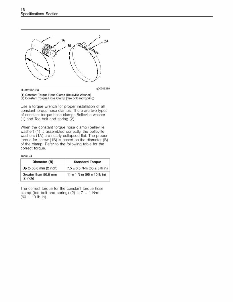
g00906389Illustration 23
(1) Constant Torque Hose Clamp (Belleville Washer)(2) Constant Torque Hose Clamp (Tee bolt and Spring)
Use a torque wrench for proper installation of allconstant torque hose clamps. There are two typesof constant torque hose clamps:Belleville washer(1) and Tee bolt and spring (2)
When the constant torque hose clamp (bellevillewasher) (1) is assembled correctly, the bellevillewashers (1A) are nearly collapsed flat. The propertorque for screw (1B) is based on the diameter (B)of the clamp. Refer to the following table for thecorrect torque.
Table 24
Diameter (B) Standard Torque
Up to 50.8 mm (2 inch) 7.5 ± 0.5 N·m (65 ± 5 lb in)
Greater than 50.8 mm(2 inch)
11 ± 1 N·m (95 ± 10 lb in)
The correct torque for the constant torque hoseclamp (tee bolt and spring) (2) is 7 ± 1 N·m(60 ± 10 lb in).
17Index Section
Index
A
Air Brake Fittings ................................................... 13Air Conditioning Fittings......................................... 13
B
Bulkhead Nuts ....................................................... 11
E
English (SAE) Fasteners ....................................... 5English (SAE) Machine Screws ......................... 6English (SAE) Nuts and Bolts ............................ 5English (SAE) Taperlock Studs .......................... 6
F
Flare Fittings.......................................................... 1237 Degree Flare Fittings .................................... 1245 Degree Flare and 45 Degree Inverted FlareFittings.............................................................. 12
G
General Information............................................... 4Ground Engaging Tool (G.E.T.) Fasteners............. 6
H
Hose Clamps......................................................... 15Constant Torque Hose Clamps .......................... 15Worm Drive Band Type Clamps......................... 15
I
Important Safety Information ................................. 2Installation of Fittings............................................. 7
Installation of Adjustable STOR Fittings ............ 8Installation of Split Flange Couplings................. 7
M
Metric (ISO) Fasteners .......................................... 4Metric (ISO) Machine Screws ............................ 5Metric (ISO) Nuts and Bolts ............................... 4Metric (ISO) Taperlock Studs............................. 5
Miscellaneous Fittings ........................................... 14Flex Fittings........................................................ 15Hi Duty Tube Fittings (Shear Sleeve) ................. 14SAE Flareless Fittings........................................ 15
O
O-Ring Face Seal Fittings ..................................... 11
P
Plugs...................................................................... 9Drain Plugs with Straight Threads ..................... 10Straight Thread O-Ring Plugs (Hex Drive)......... 9Straight Thread O-Ring Plugs (Mechanical JointTube Assemblies)............................................. 10
Straight Thread O-Ring Plugs (Socket Drive) .... 9
S
Specifications Section ........................................... 4Straight Thread O-Ring Fittings............................. 8
T
Table of Contents................................................... 3Tapered Pipe Thread Fittings ................................ 14

18Index Section

19Index Section

©2003 CaterpillarAll Rights Reserved Printed in U.S.A.