Embed Size (px)
Citation preview

JOURNAL OF NANO- AND ELECTRONIC PHYSICS ЖУРНАЛ НАНО- ТА ЕЛЕКТРОННОЇ ФІЗИКИ
Vol. 8 No 2, 02034(8pp) (2016) Том 8 № 2, 02034(8cc) (2016)
2077-6772/2016/8(2)02034(8) 02034-1 2016 Sumy State University
Diffraction Radiation Oscillator with Asymmetric Open Resonant System.
Part 2. Hot Test Results of Diffraction Radiation Oscillator
V.S. Miroshnichenko*, I.O. Kovalov
O.Ya. Usikov Institute for Radiophysics and Electronics NAS of Ukraine
12, Akad. Proskury St., 61085 Kharkiv, Ukraine
(Received 04 April 2016; revised manuscript received 09 June 2016; published online 21 June 2016)
The hot test results of diffraction radiation oscillator with asymmetric open resonant system, in which
the periodic structure was shifted to the field spot periphery of the operating TEM00q-mode, are presented.
It is shown, that displacement of the periodic structure, in double grating form, to field spot periphery of
TEM00q-mode allows extending the single-mode frequency tuning range and improves the overall efficiency
of diffraction radiation oscillator. The mode competition features in diffraction radiation oscillator with
double grating and asymmetric open resonant system are considered. The investigations were carried out
in 8-mm waveband.
Keywords: Diffraction radiation oscillator, Open resonant system, Periodic structure, Double grating,
Millimeter waves.
DOI: 10.21272/jnep.8(2).02034 PACS numbers: 84.40.Fe, 85.40. – x, 42.82Bg
1. INTRODUCTION
Diffraction radiation oscillator (DRO) with periodic
structure in double grating form has more higher level
of output power and efficiency due to effective using of
the ribbon electron beam on its thickness [1, 2]. The
significant disadvantage such DRO is relatively narrow
frequency tuning range, as a result of the strong double
grating influence on resonant field of operating
TEM00q-mode into its open resonant system (ORS). To
extend DRO frequency tuning range we suggest using
of asymmetric ORS, in which the double grating is dis-
placed from longitudinal axis of the system to field spot
periphery of operating TEM00q-mode. In the first part of
present paper [3] the cold test results of resonant
modes properties, exciting in the asymmetric ORS with
double grating, were shown. It was established, that
the double grating shifting to field spot periphery re-
duces its influence on resonant field of operating
TEM00q-mode and decreases ohmic loss in the grating,
that contributes to increase of ORS Q-factor and to
expand of single-mode frequency tuning range.
In the present paper the hot test results of the
DRO-model with asymmetric ORS are presented.
The mirrors parameters and the optimal displace-
ment of double grating from resonator longitudinal
axis were used according to the cold test results of
the resonant modes properties in asymmetric ORS
[3]. In order to estimate the advantages of DRO with
the asymmetric ORS, the measurements of output
characteristics of the DRO-model were carried out in
parallel for symmetric and asymmetric location of
the double grating in the field spot of operating
TEM00q-mode. For the DRO-model with asymmetric
and symmetric ORS a comparison of following output
parameters were conducted: single-mode frequency
tuning range, oscillations starting current, output
power level and overall efficiency of the oscillator.
Also in the present paper the feautures of modes
competition in DRO-model with symmetric and
asymmetric ORS were analyzed. The investigations
were carried out in 8-mm waveband.
2. DISMOUNTABLE DRO-MODEL AND HOT
TEST EQUIPMENT
For experimental investigations the dismountable
model of DRO with symmetric and asymmetric ORS,
operating under continuous vacuum pumping, was
used (Fig. 1). The DRO-model included: cylindrical vac-
uum chamber 1 with inner diameter 80 mm; moving
spherical mirror unit 2; flat mirror unit 3 with a double
grating 4 and electron gun 5. The cylindrical grooves
with vacuum rubber at the each mirror units provided
coincidence of the longitudinal ORS axis with the vacu-
um chamber axis. The electron gun formed ribbon elec-
tron beam with cross-section 0.12 3.8 mm2, which was
passed in the double grating channel of width 0.30 mm.
The electron beam axis was placed at the double grat-
ing half-height. The one side of double grating was lev-
eled to the flat mirror surface. The external electro-
magnet 7 provided focused magnetic field with strength
B 0.5 T. The interception of electron beam by double
grating was controlled by isolated collector 8. The flat
mirror unit 3 allowed symmetric placement of the dou-
ble grating relative to ORS axis, and also its shifted
location along OX axis to field spot periphery of
TEM00q-mode.
The measurements of output parameters had been
carried out at pulsed operation, that allowed to de-
crease thermal heating of DRO-model in ~ 4 times. The
accelerating voltage pulses with controlled amplitude
(2.5 4.0) kV and repetition frequency 50 Hz were fed
by power supply without ripple filter. The oscillation
pulse length was ~ 2 ms at duty cycle ~ 10 %, that al-
lowed direct measurements of output power by wattme-
ter with the thermoelectric transducer (Pmax 10 W).
The oscillation frequency of DRO-model had been con-
trolled by the resonance wavemeter (Fig. 2).

V.S. MIROSHNICHENKO, I.O. KOVALOV J. NANO- ELECTRON. PHYS. 8, 02034 (2016)
02034-2
Fig. 1 – The schematic of the dismountable DRO-model, oper-
ating under continuous vacuum pumping: 1 – cylindrical
chamber; 2 – moving spherical mirror unit; 3 – flat mirror
unit; 4 – double grating; 5 – electron gun; 6 – ribbon electron
beam; 7 – electromagnet; 8 – isolated collector
Fig. 2 – The schematic of hot test equipment for the DRO-
model: 1 – dismountable DRO-model; 2 – directional coupler
(– 30 dB); 3 – wattmeter; 4 – adjustable attenuator; 5 – reso-
nance wavemeter; 6 – detector section; 7 – oscilloscope
The TEM00q-mode identification, excited in DRO by
electron beam at oscillation frequency f, was made on
accelerating voltage amplitude Ua, which satisfies the
synchronism of electron beam velocity ve with phase
velocity vph for 1-st space harmonic of the double grat-
ing field:
[Volt]1093,5 5phphe U
lcvv
, (1)
where c is the speed of light, l is the grating period, is
free-space wavelength. Also, for the TEM00q-mode iden-
tification we took into account the resonant distance
between mirrors D00q(f), which was defined at the cold
test of ORS parameters [3]. Note, that for the TEM00q-
mode we assumed that longitudinal index q describes
only the number of resonant field variation along OZ in
the intermirror space, as in OR with smooth mirrors.
For the higher TEMmnq-modes the transversal indexes
m, n describe the number of field variation along OX
and OZ axis (Fig. 1).
Let’s designate as f – the frequency for complete
matching of “half-wave” double grating with resonant
field:
2
21
2
cr
b
b
cf
, (2)
where b is the double grating height along OZ axis
(Fig. 1), cr is a critical wavelength of the H10-mode in
the elementary waveguide, formed by opposite slots of
double grating [3]. At frequency f the resonant dis-
tances Dmnq(f) for TEMmnq-modes can be defined from
the resonant condition in semispherical OR with
smooth mirrors:
sph
mnqmnq
R
Dnmq
D 21arccos1
2
12
. (3)
Initially, in the experiment, to make a correct prop-
erties comparison of DRO-model with symmetric and
asymmetric ORS, the double grating was placed sym-
metric to longitudinal ORS axis (OZ axis), and then it
was displaced along OX axis to the optimal distance
= 6.0 mm [3]. The used mirrors in DRO-model had the
same parameters, as it was at the cold test of ORS [3]:
the spherical mirror had curvature radius Rsph = 50 mm
and diameter 55 mm; the flat mirror with double
grating had diameter 58 mm and was symmetrically
truncated on two sides to 32 mm to allocate electron
gun and collector in DRO-model.
3. DRO-MODEL WITH DOUBLE GRATING OF
HEIGHT B 8.0 MM
The possibility of extending the single-mode fre-
quency tuning range at significant growth of ORS Q-
factor was shown by the cold test of resonant modes
properties in asymmetric ORS with a double grating.
However, many additional factors influence on the out-
put parameters of DRO. So, just carrying out the hot
test of DRO with the asymmetric ORS by oscillations
operation allows us to estimate the advantage of its
using in DRO-modifications.
The oscillation starting current and output power
level of DRO througout frequency tuning range were
determined at hot test. The loaded Q-factor and the
coupling coefficient of ORS on operating TEM00q-mode
were defined at cold test [3]. In DRO-model we used the
double grating with length L 25 mm, grating period
l 1.00 mm, slots width d 0.50 mm, and slots depth
h 2.56 mm. The double grating height along longitu-
dinal ORS axis was b 8.0 mm (OZ axis on Fig. 1). The
selected parameters of double grating provide the com-
plete phase matching with resonant field at frequency
f 33.7 GHz.
The investigations of DRO output power level along
the frequency tuning range were measured at electron
beam current Ia 120 mA. The output power maximum
on the operating TEM004-mode in DRO with the sym-
metric ORS was observed on frequencies near
f 33.7 GHz, and was Pmax 39 W. The frequency tun-
ing range at the output power level P 0.5 Pmax was
f/f 6.3 %. In DRO with the asymmetric ORS, when
the double grating was shifted on 6.0 mm, the out-
put power maximum on the operating TEM004-mode
was observed on frequency f 32.8 GHz and was

DIFFRACTION RADIATION OSCILLATOR WITH… J. NANO- ELECTRON. PHYS. 8, 02034 (2016)
02034-3
Pmax 34 W. The frequency tuning range extended to
low-frequency region and was: f/f 9.4% (Fig. 3a).
The oscillation starting current in DRO with the
asymmetric ORS increased in 1.5 2 times in compari-
son with starting current in DRO with symmetric
placement of double grating and was Ist (4560) mA
at frequencies near f (Fig. 3b).
а
b
c
Fig. 3 – The characteristics of DRO-model with symmetric
and asymmetric ORS at operation on TEM004-mode
The increase of loaded Q-factor in asymmetric ORS
on TEM004-mode was not significant (Fig. 3c), therefore
the starting current growth probably due to resonant
field amplitude decrease in double grating by its dis-
placement to field spot periphery of TEM004-mode. In
the same time, the significant growth of coupling coeffi-
cient in asymmetric ORS (Fig. 3c) promoted the
growth of overall efficiency of DRO and the growth of
output power level at low-frequency region.
The resonant effect of the radiation loss on the fre-
quency tuning range was more clearly demonstrated,
when DRO operated on TEM006-mode. Thus, the maxi-
mal output power of DRO was observed near f inde-
pendently from the type of used ORS and was
Pmax 34 W (Fig. 4a). In DRO with asymmetric ORS,
the frequency tuning range extended to f/f 8.5 %
and the drops of the output power reduced at frequency
tuning.
a
b
c
Fig. 4 – The characteristics of the DRO-model with symmetric
and asymmetric ORS at operation on TEM006-mode
The oscillation starting current in DRO with asym-
metric ORS growth not more than in 1.5 times (Fig. 4b)
and on frequencies near f was Ist (4144) mA. Here,
the increasing of loaded Q-factor in asymmetric ORS
plays an essential role (Fig. 4c). The coupling coefficient

V.S. MIROSHNICHENKO, I.O. KOVALOV J. NANO- ELECTRON. PHYS. 8, 02034 (2016)
02034-4
of asymmetric ORS reached the maximum 1.6 on
frequencies near f.
A comparison of the beam-field interaction efficien-
cy in DRO with symmetric and asymmetric ORS had
been carried out on frequencies near f,, where DRO
had maximal output power throughout frequency tun-
ing range. The first investigations of efficiency on
beam-field interaction were realized in DRO with dou-
ble grating length L 25 mm 3w0y (w0y is the field
spot radius on flat mirror along OY axis). For DRO-
operation on TEM006-mode the linear growth of output
power at beam current increase was observed in DRO
with symmetric and asymmetric ORS (Fig. 5a). The
overall efficiency N in DRO with symmetric ORS
reached saturation Nmax 8.4 % at beam current
Ia 120 mA. In DRO with asymmetric ORS overall effi-
ciency reached saturation Nmax 7.9 % at beam current
Ia 140 mA.
a
b
Fig. 5 – The efficiency and output power of DRO with sym-
metric ORS and asymmetric ORS for double grating length
L 25 mm (a) and L 17 mm (b)
When we shortened the double grating length to
L 17 mm 2w0y the saturation of overall efficiency
wasn’t observed up to beam current Ia 150 mA both in
DRO with symmetric ORS and with asymmetric ORS
(Fig. 5b). In DRO with asymmetric ORS at beam cur-
rent Ia 90 mA the output power and overall efficiency
of DRO exceeded the same parameters for DRO with
symmetric ORS. The maximal output power and over-
all efficiency of DRO with the asymmetric ORS were
obtained at beam current Ia 153 mA and were:
Nmax 11 %; Pmax 60 W. For DRO with symmetric
ORS the maximal output power and overall efficiency
at beam current Ia 150 mA were: Nmax 9.4%;
Pmax 50 W.
4. DRO-MODEL WITH DOUBLE GRATING OF
HEIGHT B 10.0 MM
For DRO with double grating the significant elonga-
tion of H10-mode in elementary waveguides, formed by
opposite slots of double grating, is typical. This fact
allows using in DRO the broader electron beam, that is
especially important at operating in short millimeter
waves [2]. On the other hand, selection of double grat-
ing parameters, which provides high elongation of H10-
mode in its cell, is conducted by narrowing of DRO fre-
quency tuning range and decreasing of ORS Q-factor
due to ohmic loss growth in double grating. The prob-
lems can be overcome by using in DRO an asymmetric
OR with the double grating, shifted to field spot pe-
riphery of operating TEM00q-mode.
The verification of asymmetric ORS influence on
output characteristics of DRO at double grating height
increasing was conducted on DRO-model with double
grating of height b 10.0 mm. The used ORS was in
semispherical OR form (focusing mirror with curvature
Rsph 50 mm and aperture 55 mm). The other double
grating parameters were: grating length – L 32 mm;
grating period – l 1.00 mm; slots width d 0.50 mm,
and slots depth h 2.67 mm. The estimated frequency
of the complete phase matching of double grating with
resonant field was: f 31.0 GHz.
The output power maximum of DRO-model with
symmetric ORS at operating on TEM004-mode was ob-
served near f 31.0 GHz and was Pmax 25 W, the
frequency tuning range at the output power level
P 0.5 Pmax was f/f 5.2%. When the double grating
was shifted on 6.0 mm from ORS longitudinal axis,
the oscillation output power maximum increased to
Pmax 32 W, and the frequency tuning range extended
to f/f 6.8% (Fig. 6a). Due to increasing of the inter-
action space length to L 32 mm 3.6 w0y the oscilla-
tion starting current in DRO with symmetric ORS was
only Ist 15 mA. The oscillation starting current in
DRO with asymmetric ORS increased in ~ 2 times and
was Ist (2433) mA at frequencies f (29.5-31.0) GHz
(Fig. 6b).
A comparison of efficiency on beam-field interaction
in DRO-model with the double grating of height
b 10.0 mm had been carried out at frequency
f 31.0 GHz. It was established, that overall efficiency
in DRO with symmetric ORS reached saturation
Nmax 7.5 % at beam current Ia 100 mA, and when we
used asymmetric ORS the overall efficiency increased
without saturation to Nmax 8.8 % at beam current
Ia 144 mA (Fig. 6c).
5. MODE COMPETITION FEATURES IN DRO
WITH SYMMETRIC AND ASYMMETRIC ORS
Mode competition, excited by electron beam in ORS,
significantly influences on DRO output parameters.
Especially strong mode competition phenomenon ob-
served when symmetric ORS was used in DRO. Thus,
for DRO with symmetric OR in hemispherical form,

DIFFRACTION RADIATION OSCILLATOR WITH… J. NANO- ELECTRON. PHYS. 8, 02034 (2016)
02034-5
a
b
c
Fig. 6 – The output characteristics of DRO-model with double
grating of height b 10 mm at operating on TEM004-mode
the spectrum crashing of resonant modes is observed
near semiconfocal geometry at D 0.5Rsph. In this case,
according to the dispersion equation (3) the resonance
frequencies placed closely for the fundamental TEM00q-
mode and higher transversal TEMmn(q-1)-modes with
transversal indexes m + n 4.
The usage in DRO an asymmetric ORS allows sig-
nificant decrease the influence of mode degeneracy
near semiconfocal geometry, that was confirmed at ex-
perimental investigations of DRO-model with double
grating of height b 8.0 mm and interaction space
length L 25 mm (Rsph 50 mm). So, when DRO oper-
ated on TEM005-mode near the semiconfocal geometry
(D 25 mm), the asymmetric ORS usage allowed sig-
nificant the frequency tuning range extension without
decreasing of DRO output power level. Also, for DRO
with symmetric ORS, operated on TEM005-mode, the
frequency tuning range was f/f 3.8 % due to modes
degeneracy. For DRO with asymmetric ORS the fre-
quency tuning range on TEM005-mode extended to
f/f 6.2 % (Fig. 7).
Fig. 7 – The frequency tuning range of DRO with symmetric
and asymmetric ORS at operating on TEM005-mode near semi-
confocal geometry at D Rsph 25 mm
Significant elongation of H10-mode in the elementary
waveguides, formed by opposite slots of double grating
[3] leads to slope increasing of dispersion curve D00q(f) for
fundamental TEM00q-mode, especially at the low-
frequency tuning range of DRO at cr. For higher
TEMmnq-modes the influence of double grating on reso-
nant field is negligible and their dispersion curves
Dmnq(f) have a smaller slope and can be defined accord-
ing to the resonance condition in OR with smooth mir-
rors (3). The difference in slope of dispersion curves D(f)
for operating TEM00q-mode and higher TEMmnq-modes
may leads to mode degeneracy and their competition at
low-frequencies of DRO tuning range [4]. Besides, owing
to small asymmetry in DRO-model, caused by mirrors
distortion, a competition of operating TEM00q-mode oc-
curs both with even and odd higher TEMmnq-modes.
For example, consider the modes degeneracy fea-
tures in DRO-model with symmetric and asymmetric
ORS (Rsph 50 mm; b 8.0 mm; f 33.7 GHz) at oper-
ating on TEM004-mode. The output characteristics of
DRO-operating on TEM004-mode are shown on Fig. 3.
The experimental dispersion curves D004(f) for DRO-
operating on TEM004-mode with symmetric and asym-
metric ORS are shown on Fig. 8. Here the dispersion
curves for nearest resonant modes in hemispherical OR
with smooth mirrors are shown by solid lines: TEM403-
mode (Fig. 8, curve 1); TEM004-mode (Fig. 8, curve 2)
and TEM503-mode (Fig. 8, curve 3).
The competition of operating TEM004-mode with the
higher ones should be expected in DRO near the inter-
section points of the dispersion curves. Thus, for DRO-
model with symmetric ORS the intersection point of the
dispersion curves for the TEM004 mode and higher
TEM503-mode is on frequency f 31.6 GHz (Fig. 8, point
А). In DRO-model with asymmetric ORS the influence
of double grating on resonant field decreases, and dis-
persion curve slope for operating TEM004-mode is di-
minished. As a result, the intersection point of disper-
sion curves for TEM004- and TEM503-modes shifts to the
low-frequency region (Fig. 8, point B), and this fact
leads to extension of DRO frequency tuning range on
TEM004-mode without mode competition (Fig. 3a).

V.S. MIROSHNICHENKO, I.O. KOVALOV J. NANO- ELECTRON. PHYS. 8, 02034 (2016)
02034-6
Fig. 8 – Degeneracy mode features in DRO with symmetric
and asymmetric ORS (dispersion curves Dmnq(f) for the reso-
nant modes in OR with smooth mirrors are shown by solid
lines: 1 – TEM403-mode; 2 – TEM004-mode; 3 – TEM503-mode)
The shown above cases of modes competition influ-
ence on DRO output characteristics by means of energy
exchange between modes at resonant field. But DRO
operating can be affected by the ORS modes, which
don’t interact through resonant field, but directly in-
teract with electron beam. We’ll call this case, as mode
competition on beam accelerating voltage. For DRO
with double grating, operated on TEM00q-mode, the
potential competitor on accelerating voltage is the
TEM01q-mode with two antiphase field spots along in-
teraction space [5, 6]. The suppression of DRO excita-
tion on TEM01q-mode is realized by reduction of ORS
mirrors aperture along OY axis (Fig. 1) and truncation
of interaction space length. A more radical way is the
DRO-operating only on TEM01q-mode, using the shift-
ing of grating slots periodicity in the center of interac-
tion space [7].
For DRO with asymmetric ORS, operated on
TEM00q-mode, except the TEM01q-mode a potential
competitor on accelerating voltage is the TEM10q-mode
with two field spots along OX axis (Fig. 9a). The DRO
excitation on TEM10q-mode isn’t observed when we use
the symmetric ORS, due to symmetric location of dou-
ble grating in anti-phase field spots of this mode. In
DRO with asymmetric ORS the double grating is
placed on flat mirror near the field maximum of
TEM10q-mode (Fig. 9a), that promotes the effective en-
ergy exchange between electron beam and resonant
field of TEM10q-mode. The resonant frequencies of these
modes at fixed distance between ORS mirrors satisfy
the inequality f10q f00q, and DRO electronic tuning
zone of TEM10q-mode is placed above on DRO electronic
tuning zone of TEM00q-mode (Fig. 9b). This leads to
hard condition of DRO-operating on TEM00q mode near
the output power maximum and to failure of oscilla-
tions at the increase of beam current value.
The experimental studies of the competition fea-
tures by accelerating voltage between TEM004 and
TEM104-modes had been carried out in DRO-model with
asymmetric ORS and double grating of height
b 10.0 mm. The output characteristics of such DRO at
the tuning on TEM004-mode are shown on Fig. 6. The
resonant frequencies separation of TEM104 and TEM004-
modes at the equal distance D between ORS mirrors
was f104 – f004 1,3 GHz throughout the all tuning
range (Fig. 10a), i.e. the direct mode competition on
resonant field wasn’t observed. The excitation of oscil-
lation in DRO-model on TEM104-mode was observed at
starting current, comparable to the oscillation starting
current on TEM004-mode. At the DRO-operating on
TEM104-mode the resonant increase of starting current
was observed near the frequency f104 f 31.0 GHz at
D 21.5 mm (Fig. 10a), caused by the degeneracy of the
TEM104 and TEM014 modes in ORS at complete phase
matching of double grating with resonant field.
a
b
Fig. 9 – The sketch of field structure of TEM00q and TEM10q-
modes on the flat mirror of asymmetric ORS (a) and the rela-
tive position of DRO electronic tuning zones for TEM00q and
TEM10q-modes (b)
In the experiment, at the same distance D between
ORS mirrors we registered the value of accelerating
voltage at the beginning (Umin) and at the end of elec-
tronic tuning zone (Umax) for DRO-operation on TEM004
and TEM104-modes.
The synchronous accelerating voltage Uph, which
satisfies the velocity synchronism between electron
beam and 1-st space harmonic of doble grating periodic
field for TEM004 and TEM104-modes was obtained ac-
cording to (1) on measured in experiment resonant fre-
quencies of modes at the given distance D between mir-
rors of ORS.
The beginning of DRO electronic tuning zone on
TEM004-mode (Umin-004) practically coincided with syn-
chronous accelerating voltage for TEM004-mode (Uph-004)
(Fig. 10b). The end of DRO electronic tuning zone on
DIFFRACTION RADIATION OSCILLATOR WITH… J. NANO- ELECTRON. PHYS. 8, 02034 (2016)
02034-7
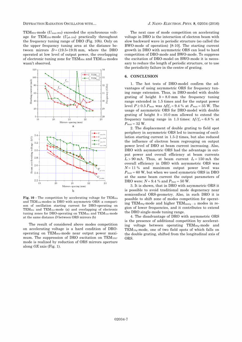
TEM004-mode (Umax-004) exceeded the synchronous volt-
age for TEM104-mode (Uph-104) practically throughout
the frequency tuning range of DRO (Fig. 10b). Only on
the upper frequency tuning area at the distance be-
tween mirrors D (19.519.9) mm, where the DRO
operated at low level of output power, the overlapping
of electronic tuning zone for TEM004 and TEM104-modes
wasn’t observed.
a
b
Fig. 10 – The competition by accelerating voltage for TEM004
and TEM104-modes in DRO with asymmetric ORS: a compari-
son of oscillation starting current for DRO-operating on
TEM004 and TEM104-mode (a) and overlapping of electronic
tuning zones for DRO-operating on TEM004 and TEM104-mode
at the same distance D between ORS mirrors (b)
The result of considered above modes competition
on accelerating voltage is a hard condition of DRO-
operating on TEM004-mode near output power maxi-
mum. The suppression of DRO excitation on TEM104-
mode is realized by reduction of ORS mirrors aperture
along OX axis (Fig. 1).
The next case of mode competition on accelerating
voltage in DRO is the interaction of electron beam with
slow backward wave in periodic structure (so called the
BWO-mode of operation) [8-10]. The starting current
growth in DRO with asymmetric ORS can lead to hard
competition of DRO-mode and BWO-mode. To suppress
the excitation of DRO-model on BWO-mode it is neces-
sary to reduce the length of periodic structure, or to use
the periodicity failure in the centre of grating.
6. CONCLUSION
1. The hot tests of DRO-model confirm the ad-
vantages of using asymmetric ORS for frequency tun-
ing range extension. Thus, in DRO-model with double
grating of height b 8.0 mm the frequency tuning
range extended in 1.5 times and for the output power
level P 0.5 Pmax was f/f 9.4 % at Pmax 35 W. The
usage of asymmetric ORS for DRO-model with double
grating of height b 10.0 mm allowed to extend the
frequency tuning range in 1.3 times: f/f 6.8 % at
Pmax 32 W.
2. The displacement of double grating to field spot
periphery in asymmetric ORS led to increasing of oscil-
lation starting current in 1.5-2 times, but also reduced
the influence of electron beam regrouping on output
power level of DRO at beam current increasing. Also,
DRO with asymmetric ORS had the advantage in out-
put power and overall efficiency at beam currents
Ia 90 mA. Thus, at beam current Ia 150 mA the
overall efficiency in DRO with asymmetric ORS was
N 11 % and maximum output power level was
Pmax 60 W, but when we used symmetric ORS in DRO
at the same beam current the output parameters of
DRO were: N 9.4 % and Pmax 50 W.
3. It is shown, that in DRO with asymmetric ORS it
is possible to avoid traditional mode degeneracy near
semiconfocal ORS-geometry. Also, in such DRO it is
possible to shift zone of modes competition for operat-
ing TEM00q-mode and higher TEMmn(q – 1) modes in re-
gion of lower frequencies, and it contributes to extend
the DRO single-mode tuning range.
4. The disadvantage of DRO with asymmetric ORS
is the presence of additional competition by accelerat-
ing voltage between operating TEM00q-mode and
TEM10q-mode, one of two field spots of which falls on
the double grating, shifted from the longitudinal axis of
ORS.
V.S. MIROSHNICHENKO, I.O. KOVALOV J. NANO- ELECTRON. PHYS. 8, 02034 (2016)
02034-8
Генератор дифракційного випромінювання з асиметричною відкритою
резонансною системою. Частина 2. Результати “гарячих” досліджень генератора
дифракційного випромінювання
В.С. Мірошниченко, Є.О. Ковальов
Інститут радіофізики та електроніки ім. О.Я. Усикова НАН України,
вул. Академіка Проскури, 12, 61085 Харків, Україна
Представлені результати “гарячих” досліджень генератора дифракційного випромінювання з
асиметричною відкритою резонансною системою, в якій періодична структура зміщена на периферію
плями поля робочої TEM00q-моди. Показано, що розміщення періодичної структури у вигляді здвоєної
гребінки на периферії плями поля TEM00q-моди дає можливість розширити одномодовий діапазон пе-
ребудови по частоті та підвищити загальний ККД генератора дифракційного випромінювання. Розг-
лянуто особливості конкуренції мод в генераторі дифракційного випромінювання зі здвоєною гребін-
кою та асиметричною відкритою резонансною системою.. Дослідження виконані у 8-мм діапазоні дов-
жин хвиль.
Ключові слова: Генератор дифракційного випромінювання, Відкрита резонансна система Періодич-
на структура, Здвоєна гребінка, Міліметрові хвилі.
Генератор дифракционного излучения с асимметричной открытой
резонансной системой. Часть 2. Результаты “горячих” исследований генератора
дифракционного излучения
В.С. Мирошниченко, Е.А. Ковалев
Институт радиофизики и электроники им. А.Я. Усикова НАН Украины,
ул. Академика Проскуры, 12, 61085 Харьков, Украина
Представлены результаты “горячих” исследований генератора дифракционного излучения с
асимметричной открытой резонансной системой, в которой периодическая структура смещена на пе-
риферию пятна поля рабочей TEM00q-моды. Показано, что размещение периодической структуры в
виде сдвоенной гребенки на периферии пятна поля TEM00q-моды дает возможность расширить одно-
модовый диапазон перестройки по частоте и улучшить общий КПД генератора дифракционного излу-
чения. Рассмотрены особенности конкуренции мод в генераторе дифракционного излучения со сдво-
енной гребенкой и асимметричной открытой резонансной системой. Исследования выполнены в 8-мм
диапазоне длин волн.
Ключевые слова: Генератор дифракционного излучения, Открытая резонансная система, Периоди-
ческая структура, Сдвоенная гребенка, Миллиметровые волны.
REFERENCES
1. Diffraction radiation generators (Ed. by V.P. Shestopalov)
(Kiev: Naukova dumka: 1991), [in Russian].
2. V.K. Korneenkov, V.S. Miroshnichenko, B.K. Skrynnik,.
Telecommunicat. Radio Eng. 51 No 6-7, 144 (1997).
3. V.S. Miroshnichenko, I.O. Kovalov, J. Nano- Electron.
Phys. 8 No 2, 02033 (2016).
4. V.S. Miroshnichenko, Telecommunicat. Radio Eng. 68
No 3, 231 (2009).
5. Yu.I. Evdokimenko, K.A. Lukin, I.D. Revin,
B.K. Skrynnik, Zh. Tekh. Fiz. 52 No 3, 525 (1982) [in Rus-
sian].
6. A.N. Solovyov, M.B. Tseytlin, Radiotekh. Electron. 27
No 2, 368 (1982) [in Russian].
7. V.S. Miroshnichenko, E.B. Senkevich, A.G. Pivovarova,
D.V. Yudintsev, Radiophys. Quantum Electron. 53 No 3,
182 (2010).
8. I.M. Balaklitsky, V.G. Kurin, B.K. Skrynnik, Ukr. Phys. J.
15 No 5, 717 (1970), [in Russian].
9. F.S. Rusin, V.P. Kostromin, Radiotekh. Electron. 30 No 5,
994 (1985) [in Russian].
10. M.Yu. Demchenko, V.K. Korneenkov, V.S. Miroshnichenko,
B.K. Skrynnik, Radiofizika i electronika 4 No 2, 99 (1999)
[in Russian].


![Avn13 durham[8pp]](https://img.pdfslide.us/doc/110x75/568c37fc1a28ab02359d7913/avn13-durham8pp.jpg)

