Embed Size (px)
Citation preview
WIRELESS COMMUNICATIONS AND MOBILE COMPUTINGWirel. Commun. Mob. Comput. 2016; 16:2422–2435Published online 28 July 2016 in Wiley Online Library (wileyonlinelibrary.com). DOI: 10.1002/wcm.2692
RESEARCH ARTICLE
Differential modulation for asynchronous two-wayrelay systems over frequency-selective fading channelsAhmad Salim1* and Tolga M. Duman2
1 Department of Electrical and Computer Engineering, University of Illinois at Chicago, Illinois, U.S.A.2 Department of Electrical and Electronics Engineering (EEE), Bilkent University, Ankara 06800, Turkey
ABSTRACT
We propose two schemes for asynchronous multi-relay two-way relay (MR-TWR) systems in which neither the users northe relays know the channel state information. In an MR-TWR system, two users exchange their messages with the help ofNR relays. Most of the existing works on MR-TWR systems based on differential modulation assume perfect symbol-levelsynchronization between all communicating nodes. However, this assumption is not valid in many practical systems, whichmakes the design of differentially modulated schemes more challenging. Therefore, we design differential modulationschemes that can tolerate timing misalignment under frequency-selective fading. We investigate the performance of theproposed schemes in terms of either probability of bit error or pairwise error probability. Through numerical examples, weshow that the proposed schemes outperform existing competing solutions in the literature, especially for high signal-to-noise ratio values. Copyright © 2016 John Wiley & Sons, Ltd.
KEYWORDS
two-way relay channels; differential modulation; synchronization; orthogonal frequency division multiplexing
*Correspondence
Ahmad Salim, Department of Electrical and Computer Engineering, University of Illinois at Chicago, Illinois, U.S.A.E-mail: [email protected] of this work was performed during the first author’s PhD study at Arizona State University (Salim, A. Transmission Strategies forTwo-Way Relay Channels. Arizona State University, 2015).
1. INTRODUCTION
Most of the existing schemes for two-way relay (TWR)systems assume known channel state information (CSI)(e.g., [1,2] and the references therein). Because of manyreasons, such as the large overhead of the channel estima-tion process or relatively rapid variations of the channel,perfect CSI is not always available. In such scenarios, usinga modulation scheme like differential phase shift keyingthat requires no CSI is a practical solution.
While there have been significant research efforts onusing differential modulation (DM) for TWR systems,most, for example [3], assume symbol-level synchroniza-tion among all nodes. In practice, many reasons such ashaving different propagation delays or different dispersivechannels, lead to a timing misalignment between the arriv-ing signals. Therefore, having a perfectly synchronizedTWR system is very difficult which, in return, rendersthe design of differentially modulated schemes more chal-lenging. In the case of synchronous TWR systems, manyschemes were proposed to address the absence of CSI, forexample [3–7]. However, little work has been conductedto tackle asynchronous communication scenarios. One sce-nario of particular interest is the use of asynchronous
multi-relay two-way relay (MR-TWR) systems in whichtiming errors not only occur at the end-users but at relaysas well.
In [4], the authors propose a DM scheme along withmaximum likelihood (ML) detection and several subopti-mal solutions for a number of relaying strategies when CSIis not available at any node. The authors further extendtheir results to the multi-antenna case based on differentialunitary space–time modulation. A simple amplify-and-forward (AF) scheme is proposed in [3] based on DM inwhich the self-interference term is estimated and removedprior to detection. The resulting bit error rate (BER) andthe optimum power allocation strategies are also studied.In [8], the authors propose a joint relay selection and AFscheme using DM. The scheme selects the relay that mini-mizes the maximum BER of the two sources. Ref. [5] pro-poses a DM scheme that uses K parallel relays, for whicha denoising function is derived to detect the sign change ofthe network coded symbol at each relay which is employedlater by the users for detection. The paper obtains aclosed form expression for the BER for the single-relaycase along with a sub-optimal power allocation scheme.Furthermore, the authors derive lower and upper boundson the BER for the multi-relay case. A low complexity
2422 Copyright © 2016 John Wiley & Sons, Ltd.
A. Salim and T. M. Duman Differential modulation for asynchronous TWR systems
differential phase shift keying-based scheme is proposedin [6] for physical-layer network coding to acquire thenetwork coded symbol at the relay without requiring CSIknowledge. Compared with the schemes in [4,5] whichrequire more complexity, this scheme shows better per-formance at high signal-to-noise ratios (SNRs). However,the detector is only derived for a binary alphabet. In [7],the authors propose a transmission and detection schemefor a differentially-modulated, two-way satellite relayingsystem in which a satellite relays signals between twoearth stations. The authors derive a simple suboptimumdetection rule and optimize rotation angles for the twousers’ constellations to improve the accuracy of channelestimation.
A few proposals in the literature consider the designof distributed space–time coding (DSTC) coupled withdifferential modulation for synchronous TWR systems,for example, [9–11]. The models in [9,10] assume two-phase transmission and the lack of a direct link betweenthe two users. On the other hand, [11] assumes a three-phase transmission and that a direct link between the twousers exists.
All the solutions discussed above have strict synchro-nization requirements for proper operation. Only a fewworks consider asynchronous TWR systems where DM isused to mitigate absence of CSI. For instance, [12] pro-poses an interference cancelation scheme to reduce theinterference from neighboring symbols caused by imper-fect synchronization. Ref. [13] extends the scheme in [12]to dual-relay TWR systems. Similar results are reportedin [14,15] for the conventional one-way relay channel.However, the schemes in [14,15] are closer to the tradi-tional differential modulation in the sense that the self-interference term, that exist for the case of TWR systems,is absent. For TWR systems, this term consists of NR faded(and possibly misaligned) copies of the considered user’ssignal, and as the fading coefficients are unknown, theschemes in [12,13] estimate this term to be able to detectthe partner’s message.
While [12,13] present important results, they arerestricted to flat fading channels, and the delays thatcan be tolerated are only within the period of a sym-bol, which make them suitable neither for time-dispersivechannels nor for systems experiencing large relative prop-agation delays. In this paper, we consider a more generalfrequency-selective fading channel model and propose twoschemes that can tolerate larger relative propagation delayscompared with [12]. Specifically, we first propose the jointblind-differential (JBD) detection scheme in which we firstperform blind channel estimation to be able to remove theself-interference component, and then perform differentialdetection. We provide an approximate closed form expres-sion for the BER for large SNR values. We then proposea scheme that is based on differential DSTC, referred toas JBD-DSTC, to fully harness the available diversity inthe system. The JBD-DSTC scheme significantly reformsthe JBD scheme in order to obtain an STC structure forthe partner’s message at each user. The pairwise error prob-
ability of this scheme along with the achievable diversity isalso discussed.
The remainder of this paper is organized as follows.Section 2 describes the system model. Section 3 details thetransmission mechanism and receiver design for the pro-posed JBD scheme along with providing a closed formexpression for the probability of error. Section 4 presentsthe JBD-DSTC scheme and the relevant performance anal-ysis in terms of the pairwise error probability (PEP).Section 5 presents numerical results obtained to evalu-ate the performance of the proposed solutions. Finally,conclusions are drawn in Section 6.
Notation: Unless stated otherwise, bold-capital lettersrefer to frequency-domain vectors, bold-lower case lettersrefer to time-domain vectors, capital letters refer to matri-ces or elements of frequency-domain vectors (dependingon the context), and lower-case letters refer to scalars orelements of time-domain vectors. If used as a superscript,the symbols T , � and H refer to transpose, element-wisecomplex conjugate and Hermitian (conjugate transpose),respectively. The notation 0N and 0N�N refer to length-N all-zero column vector and N � N all-zero matrix,respectively. F is the normalized discrete Fourier transform(DFT) matrix of size-N. The Inverse DFT (IDFT) matrixof size-N is denoted by FH . The subscript ir refers to thechannel from node i to node r.
2. SYSTEM MODEL
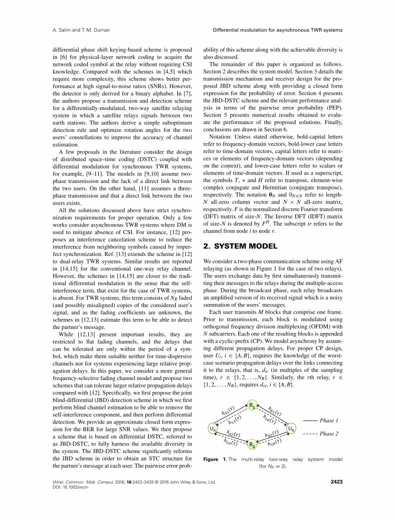
We consider a two-phase communication scheme using AFrelaying (as shown in Figure 1 for the case of two relays).The users exchange data by first simultaneously transmit-ting their messages to the relays during the multiple-accessphase. During the broadcast phase, each relay broadcastsan amplified version of its received signal which is a noisysummation of the users’ messages.
Each user transmits M blocks that comprise one frame.Prior to transmission, each block is modulated usingorthogonal frequency division multiplexing (OFDM) withN subcarriers. Each one of the resulting blocks is appendedwith a cyclic-prefix (CP). We model asynchrony by assum-ing different propagation delays. For proper CP design,user Ui, i 2 fA, Bg, requires the knowledge of the worst-case scenario propagation delays over the links connectingit to the relays, that is, dir (in multiples of the samplingtime), r 2 f1, 2, : : : , NRg. Similarly, the rth relay, r 2f1, 2, : : : , NRg, requires dri, i 2 fA, Bg.
Figure 1. The multi-relay two-way relay system model(for NR D 2).
Wirel. Commun. Mob. Comput. 2016; 16:2422–2435 © 2016 John Wiley & Sons, Ltd. 2423DOI: 10.1002/wcm
Differential modulation for asynchronous TWR systems A. Salim and T. M. Duman
The multipath fading channels from the users to therelays are modeled (in the equivalent low-pass signaldomain) by the discrete channel impulse responses (CIRs)hir,l, i 2 fA, Bg, r 2 f1, 2, : : : , NRg, l 2 f1, 2, : : : , Lirg,where Lir represents the number of resolvable paths. Simi-larly, the channels from the relays to the users are modeledby hri,l. The overall channel response over the Lir lags canbe expressed as hir.�/ D
PLirlD1 hir,lı
�� � �ir,l
�, where �
is the lag index and �ir,l is the delay of the lth path nor-malized by the sampling period TS. We assume quasi-staticfrequency-selective fading in which hir,l remain constantfor all the blocks over the same lag (l) and change inde-pendently across the different lags. We assume that hir,l isa circularly-symmetric complex Gaussian (CSCG) randomvariable (RV) with zero mean and variance of �2
ir,l. Also,the channel coefficients are independent across differentlinks. We assume half-duplex operation at all nodes.
For the JBD scheme, we further assume that the chan-nels on the same link are reciprocal, that is, hir.�/ D hri.�/
8i, r. Also, the uplink and downlink propagation delaysover the same link are assumed to be identical.
3. THE JOINT BLIND-DIFFERENTIALSCHEME
In this scheme, each user uses N parallel differentialencoders; each operating on a specific subcarrier. The datavector representing the frequency-domain message of theith user, i 2 fA, Bg, during the mth block is denoted
by X.m/i where X .m/i D
hX.m/i,1 , X.m/i,2 , : : : , X.m/i,N
iTand
X.m/i,k 2 Ai where Ai is a unit-energy, zero-mean, phase-shift keying (PSK) constellation set that is closed undermultiplication, for example, the set f˙1,˙jg, to main-tain the transmit power at a specific level. We remark thatthe encoders (and decoders) in this paper are designedfor the earlier assumptions. However, they can be modi-fied to account for constellations that do not follow theseassumptions such as quadrature amplitude modulation. Inthis case, encoding and decoding can be performed using alook-up table approach instead of a rule (as in [16]).
Using DM, the differentially encoded symbol overthe kth subcarrier of the mth block can be expressed
as S.m/i,k D X.m/i,k S.m�1/i,k , m 2 f2, 3, : : : , Mg, and
S.1/i,k D X.1/i,k . After performing IDFT, we obtain s.m/i Dhs.m/i,1 , s.m/i,2 , : : : , s.m/i,N
iTD IDFT.S .m/i /. The transmitted
signal from the ith user during the mth block, i 2 fA, Bg, isgiven by:
s.m/Tx,i D
pPi�1
�s.m/i
�(1)
where s.m/Tx,i Dhs.m/Tx,i,1, s.m/Tx,i,2, : : : , s.m/Tx,i,NCNCP,1
iT, Pi, i 2
fA, Bg, is the transmission power at the ith user and �1.�/
corresponds to the operation of appending a length NCP,1CP to the vector in its argument at each user prior to the
first phase of transmission. The length of this CP is selectedto satisfy NCP,1 > maxi,rfLir C dirg, i 2 fA, Bg, r 2 f1, 2g.
3.1. Relay processing
Having appended a CP of the proper length at each user,the received signal corresponding to the mth block at therth relay after removing the CP is given by
y.m/r Dp
PAHtl,Ar‰dArs.m/A C
pPBHtl,Br‰dBrs
.m/B Cn.m/r ,
where Htl,ir is the time-lag channel matrix correspond-
ing to the channel over the link ir, and n.m/r representslength-N noise vector at the rth relay during the mth blockwhose entries are independent and identically distributedCSCG RVs with zero mean and variance of �2
r . ‰dir , i 2fA, Bg, r 2 f1, 2, : : : , NRg, is a circulant matrix of sizeN � N whose first column is given by the N � 1 vector
dir Dh0T
dir, 1, 0T
N�dir�1
iT. Using the matrix ‰dir mim-
ics the circular shift caused by having a propagation delayof dir samples. To simplify blind channel estimation atthe end user, Rr performs conjugation and time-reversal
operations to obtain s.m/r D ��y.m/�r
�where �.�/ is
the time-reversal operator. For x D Œx1, x2, : : : , xN �T ,
�.�/ is defined element-wise as �.xn/ , xN�nC2, n D1, : : : , N and xNC1 , x1. The conjugation and reversalin the time-domain will have a conjugation effect in thefrequency-domain after taking DFT at the end user.
After processing the mixture of signals, Rr appends aCP for the second phase of transmission of length NCP,2that satisfies NCP,2 > maxr,ifLriC drig, r 2 f1, 2, : : : , NRg,i 2 fA, Bg. The rth relay transmitted signal is given by
s.m/Tx,r D
pPrGr�2
�s.m/r
�, r 2 f1, 2g (2)
where s.m/Tx,r Dhs.m/Tx,r,1, s.m/Tx,r,2, : : : , s.m/Tx,r,NCNCP,2
iT, Pr and
Gr are the transmission power and the scaling factor at therth relay, respectively, and �2.�/ corresponds to the oper-ation of appending a length NCP,2 CP to the vector inits argument.
3.2. Detection at the end-user
Because of symmetry, we only describe detection at userB. After removing the CP that was added at the relays, thereceived N-sample OFDM blocks can be written as
y.m/B D
NRXrD1
pPAPrGrHtl,rB‰drB�
�H�tl,Ar‰
�dArs.m/�A
�C
NRXrD1
pPBPrGrHtl,rB‰drB�
�H�tl,Br‰
�dBrs.m/�B
�C v
.m/B ,
2424 Wirel. Commun. Mob. Comput. 2016; 16:2422–2435 © 2016 John Wiley & Sons, Ltd.DOI: 10.1002/wcm
A. Salim and T. M. Duman Differential modulation for asynchronous TWR systems
where v.m/B represents length-N effective noise vector atuser B during the mth block which encompasses the relays’
amplified noise as well. The entries of v.m/B are indepen-dent and identically distributed CSCG RVs with zero mean
and variance of �2B,eff D �
2BC
PNRrD1 GrPr
ˇ̌̌�Hdf ,rB
�k,k
ˇ̌̌2�2
r
where �2B is the variance of the original noise terms
at user B.Let V .m/B D Fv.m/B , Pir D PiPrGr and assume that dri D
dir, r 2 f1, 2, : : : , NRg, i 2 fA, Bg. After performing DFTand noting that F� .x�/ D .Fx/�, the received signal on
the kth subcarrier of the mth block simplifies to† Y.m/B,k D
�kS.m/B,k
�C �kS.m/A,k
�C V.m/B,k where
�k D
NRXrD1
pPAr
�Hdf ,rB
�k,k
hH�df ,Ar
ik,k
e�j2�.k�1/.drB�dAr/
N ,
�k DPNR
rD1
pPBr
ˇ̌ŒHdf ,Br�k,k
ˇ̌2, V.m/B,k is the kth element
of V .m/B , and Hdf ,ir D FHtl,irFH denotes the Doppler-frequency channel matrix (also called the subcarrier cou-pling matrix) over the link ir which is a diagonal matrix inour case of quasi-static fading.
The results of [3] are adopted to estimate the parameter�k in order to remove the self-interference term. Defining,eY.m/B,k D X.m/B,k
�Y.m�1/
B,k � Y.m/B,k , we can write
eY.m/B,k D �kS.m�1/A,k
� �X.m/B,k
�� X.m/A,k
��CeV.m/B,k ,
m D 2, : : : , M,(3)
whereeV.m/B,k D X.m/B,k
�V.m�1/
B,k �V.m/B,k . At high SNR, we can
approximateeY.m/B,k
�eY.m/B,k as
eY.m/B,k
�eY.m/B,k �j�kj2ˇ̌̌S.m�1/
A,k
ˇ̌̌2 ˇ̌̌X.m/B,k � X.m/A,k
ˇ̌̌2,
m D 2, : : : , M.(4)
Taking the expected value of (4) over the constellation
points of S.m�1/A,k , X.m/A,k and X.m/B,k , we note that for the RHS,
it is the same for all m and k as the constellation sets Ai,i 2 fA, Bg are the same for all blocks and subcarriers.
We also note that S.m�1/A,k is independent from both X.m/B,k
and X.m/A,k . For a sufficiently large M, we can approximate
the ensemble average of eY.m/B,k
�eY.m/B,k by its time average.Therefore, we can obtain an estimate of j�kj, denoted byjb�kj, as
†Refer to Appendix A for details.
jb�kj2 �
MXmD2
ˇ̌̌eY.m/B,k
ˇ̌̌2.M � 1/E
�ˇ̌̌S.m�1/
A,k
ˇ̌̌2E
�ˇ̌̌X.m/B,k � X.m/A,k
ˇ̌̌2 ,
(5)
where E
�ˇ̌̌S.m�1/
A,k
ˇ̌̌2D 1 and E
�ˇ̌̌X.m/B,k � X.m/A,k
ˇ̌̌2can
be calculated easily as the corresponding set definedby K D
˚jb � aj2 j b 2 AB, a 2 AA
is finite. For
instance, if Ai D f1,�1g, i 2 fA, Bg, then K D
f0, 4g and E
�ˇ̌̌X.m/B,k � X.m/A,k
ˇ̌̌2D 2. Let YB,k Dh
Y.1/B,k , Y.2/B,k , : : : , Y.M/B,k
iT. If M is sufficiently large, we can
approximate Y HB,kYB,k as
Y HB,kYB,k � M
��2
k C j�kj2 C �2
VB
�. (6)
At high SNR, we can write
�2k C j�kj
2 �Y H
B,kYB,k
M. (7)
Therefore, we can estimate �k as
b�k �
vuut Y H
B,kYB,k
M� jb�kj
2
!U
Y H
B,kYB,k
M� jb�kj
2
!,
(8)
where U ../ is the Heaviside unit step function. Now, wecan remove the estimated self-interference term, namelyb�kS.m/B,k
�to obtain
Y.m/AB,k , Y.m/B,k �b�kS.m/B,k
�
� �kS.m/A,k
�C V.m/B,k , m D 1, : : : , M.
(9)
We can further express Y.m/AB,k as
Y.m/AB,k � X.m/A,k
�Y.m�1/
AB,k C�
V.m/B,k � X.m/A,k
�V.m�1/
B,k
�,
m D 2, : : : , M.(10)
Therefore, we write the following symbol-by-symbol
ML detection rule to recover X.m/A,k at user B
bX.m/A,k D arg minX2AA
ˇ̌̌Y.m/AB,k � X�Y.m�1/
AB,k
ˇ̌̌2(11)
D arg maxX2AA
RenY.m/AB,kY.m�1/
AB,k
�Xo
, m D 2, : : : , M.
(12)
We remark that better performance can be attained ifmultiple-symbol differential detection, as in [17], is used.However, the detection complexity will be greater.
Wirel. Commun. Mob. Comput. 2016; 16:2422–2435 © 2016 John Wiley & Sons, Ltd. 2425DOI: 10.1002/wcm

Differential modulation for asynchronous TWR systems A. Salim and T. M. Duman
3.3. Performance analysis
In this section, we provide an approximate closed formexpression for the probability of error of the JBD schemeby using results from the frequency-flat, Rayleigh-faded,single-way relay systems in [3,18].
Assume that instead of using Gr to normalize thepower at the rth relay in time domain, we use Gr,k
to normalize the power of the kth subcarrier in fre-quency domain. Note that Gr,k can be estimated forlarge M as Gr,k �
MjjYr,kjj2
without any CSI knowl-
edge at the relay where Yr,k DhY.1/r,k , Y.2/r,k , : : : , Y.M/r,k
iand Y .m/r D
hY.m/r,1 , Y.m/r,2 , : : : , Y.m/r,N
iTD DFT
�y.m/r
�.
By modeling the JBD system by an equivalentcoherent receiver with treating �k as a known
channel gain and�
V.m/B,k � X.m/A,k
�V.m�1/
B,k
�as the
equivalent noise term, we can approximate theeffective SNR over the kth subcarrier at user B as
B,k �j�kj
2
2VarhV.m/B,k
i (13)
D
PA
NRXrD1
Prˇ̌qrB,k
ˇ̌2 ˇ̌qAr,k
ˇ̌2C PA
NRXiD1
NRXjD1,j¤i
qPiPjGi,kGj,kqiB,kq�Ai,kq�jB,kqAj,k
2��2
B CPNR
rD1 Gr,kPrˇ̌qrB,k
ˇ̌2�2
r
� , (14)
where qij,k D�Hdf ,ij
�k,k and VarŒ�� is the variance operator.
As B,k in (13) is a complicated function of 2NR
Rayleigh-distributed RVs, finding its statistics (PDF, CDF,etc.) is difficult, and hence deriving the probability of erroris intractable. However, an important result in [18] for aspecial choice of the scaling factor simplifies the analysisas it results in expressing the effective SNR in terms of theharmonic mean of the instantaneous SNR of the two hops,which in turn simplifies the calculations. The adopted scal-ing factor normalizes the power of the kth subcarrier as
Gr,k D
�PA
ˇ̌̌�Hdf ,Ar
�k,k
ˇ̌̌2C PB
ˇ̌̌�Hdf ,Br
�k,k
ˇ̌̌2C �2
r
��1
.
At this point, we adopt this scaling factor to make theanalysis tractable for the JBD scheme.
Assume that �2i D �2
r D �2 8 i 2 fA, Bg, r 2
f1, 2, : : : , NRg and let 1 DPA�2 and 2 D
PNRrD1 Pr
�2 bethe per-hop SNRs for the first and second hops, respec-tively. Assuming that the CIRs are normalized such thatPLir
lD1 �2ir,l D 1, i 2 fA, Bg, r 2 f1, 2, : : : , NRg, we haveˇ̌
qir,kˇ̌� Rayleigh
�1p2
�and
ˇ̌qri,k
ˇ̌� Rayleigh
�1p2
�.
By dropping the second term of the numerator of (14) andusing 2 as the SNR for the second hop, the performance ofthe JBD scheme can be approximated by the performanceof the single relay systems in [3,18].
Assuming Binary PSK (BPSK) modulation, the averageprobability of bit error at user B in the high SNR region canbe approximated in terms of the per-relay SNR (i.e., 1)and the SNR of the second hop linking the relays to user B(i.e., 2) as
Pe,B �1
1C
1
22. (15)
We finally note that dropping the cross terms in thenumerator of (14) has the advantage of mathematicaltractability, and as the numerical examples will show lateron, the approximation closely match the actual systemperformance, especially for high SNR values.
4. THE DISTRIBUTED SPACE–TIMECODING-BASED JOINTBLIND-DIFFERENTIAL SCHEME
In multi-antenna single-way relay systems, DSTC wasproposed in [19] based on linear dispersion space-time
codes (STCs) to mimic having an STC structure at the des-tination similar to the one obtained in multi-input single-output systems that uses STCs. The system in [19] assumesthat there is CSI knowledge only at the destination. Whenthere is no CSI knowledge, the differential DSTC can beused [20].
In this section, we describe the proposed JBD-DSTCscheme based on differential DSTC transmission for amulti-relay TWR system in order to fully harness the inher-ent diversity advantage of this system. We consider a framecomposed of M blocks in which T blocks are groupedtogether. There are MG groups in a frame where MG D
M=T , and the symbols over one subcarrier from the blocksof each group correspond to one space–time codeword.
Figure 2 illustrates the encoding process at the ith userfor the T symbols over the kth subcarrier during themth group. Note that N parallel encoders are requiredfor the entire N subcarriers. As shown in Figure 2, thefrequency-domain data-bearing vector of the ith user, i 2fA, Bg, during the tth block of the mth group is denoted
by X .m,t/i where X .m,t/
i DhX.m,t/
i,1 , X.m,t/i,2 , : : : , X.m,t/
i,N
iT
and X.m,t/i,k 2 Ai. Prior to differential encoding, the vec-
tor of data symbols over the same subcarrier, k, andover all blocks of the same group, m, that is, X .m/i,k DhX.m,1/
i,k , X.m,2/i,k , : : : , X.m,T/
i,k
iT, is encoded as a T�T unitary
2426 Wirel. Commun. Mob. Comput. 2016; 16:2422–2435 © 2016 John Wiley & Sons, Ltd.DOI: 10.1002/wcm
A. Salim and T. M. Duman Differential modulation for asynchronous TWR systems
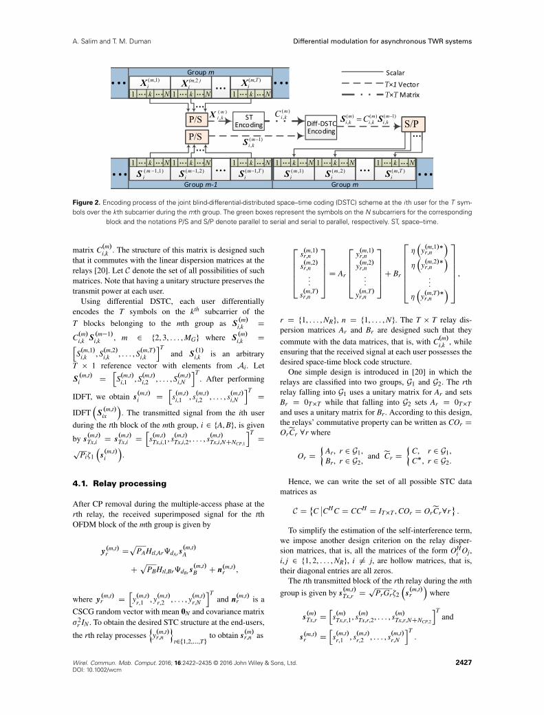
Figure 2. Encoding process of the joint blind-differential-distributed space–time coding (DSTC) scheme at the ith user for the T sym-bols over the kth subcarrier during the mth group. The green boxes represent the symbols on the N subcarriers for the corresponding
block and the notations P/S and S/P denote parallel to serial and serial to parallel, respectively. ST, space–time.
matrix C.m/i,k . The structure of this matrix is designed suchthat it commutes with the linear dispersion matrices at therelays [20]. Let C denote the set of all possibilities of suchmatrices. Note that having a unitary structure preserves thetransmit power at each user.
Using differential DSTC, each user differentiallyencodes the T symbols on the kth subcarrier of the
T blocks belonging to the mth group as S.m/i,k D
C.m/i,k S.m�1/i,k , m 2 f2, 3, : : : , MGg where S
.m/i,k Dh
S.m,1/i,k , S.m,2/
i,k , : : : , S.m,T/i,k
iTand S
.1/i,k is an arbitrary
T � 1 reference vector with elements from Ai. Let
S.m,t/i D
hS.m,t/
i,1 , S.m,t/i,2 , : : : , S.m,t/
i,N
iT. After performing
IDFT, we obtain s.m,t/i D
hs.m,t/
i,1 , s.m,t/i,2 , : : : , s.m,t/
i,N
iTD
IDFT�S.m,t/ix
�. The transmitted signal from the ith user
during the tth block of the mth group, i 2 fA, Bg, is given
by s.m,t/Tx,i D s
.m,t/Tx,i D
hs.m,t/
Tx,i,1, s.m,t/Tx,i,2, : : : , s.m,t/
Tx,i,NCNCP,1
iTD
pPi�1
�s.m,t/i
�.
4.1. Relay processing
After CP removal during the multiple-access phase at therth relay, the received superimposed signal for the tthOFDM block of the mth group is given by
y.m,t/r D
pPAHtl,Ar‰dArs
.m,t/A
Cp
PBHtl,Br‰dBrs.m,t/B C n.m,t/
r ,
where y.m,t/r D
hy.m,t/
r,1 , y.m,t/r,2 , : : : , y.m,t/
r,N
iTand n.m,t/
r is a
CSCG random vector with mean 0N and covariance matrix�2
r IN . To obtain the desired STC structure at the end-users,
the rth relay processesny.m,t/
r,n
ot2f1,2,:::,Tg
to obtain s.m/r,n as
266664s.m,1/
r,n
s.m,2/r,n
...
s.m,T/r,n
377775 D Ar
266664y.m,1/
r,n
y.m,2/r,n
...
y.m,T/r,n
377775C Br
26666664��
y.m,1/�r,n
���
y.m,2/�r,n
�...
��
y.m,T/�r,n
�
37777775 ,
r D f1, : : : , NRg, n D f1, : : : , Ng. The T � T relay dis-persion matrices Ar and Br are designed such that they
commute with the data matrices, that is, with C.m/i,k , whileensuring that the received signal at each user possesses thedesired space-time block code structure.
One simple design is introduced in [20] in which therelays are classified into two groups, G1 and G2. The rthrelay falling into G1 uses a unitary matrix for Ar and setsBr D 0T�T while that falling into G2 sets Ar D 0T�T
and uses a unitary matrix for Br. According to this design,the relays’ commutative property can be written as COr D
OreCr 8r where
Or D
Ar, r 2 G1,Br, r 2 G2,
and eCr D
C, r 2 G1,C�, r 2 G2.
Hence, we can write the set of all possible STC datamatrices as
C D˚Cˇ̌CHC D CCH D IT�T , COr D OreCr8r
.
To simplify the estimation of the self-interference term,we impose another design criterion on the relay disper-sion matrices, that is, all the matrices of the form OH
i Oj,i, j 2 f1, 2, : : : , NRg, i ¤ j, are hollow matrices, that is,their diagonal entries are all zeros.
The tth transmitted block of the rth relay during the mth
group is given by s.m,t/Tx,r D
pPrGr�2
�s.m,t/r
�where
s.m/Tx,r D
hs.m/Tx,r,1, s.m/Tx,r,2, : : : , s.m/Tx,r,NCNCP,2
iTand
s.m,t/r D
hs.m,t/
r,1 , s.m,t/r,2 , : : : , s.m,t/
r,N
iT.
Wirel. Commun. Mob. Comput. 2016; 16:2422–2435 © 2016 John Wiley & Sons, Ltd. 2427DOI: 10.1002/wcm
Differential modulation for asynchronous TWR systems A. Salim and T. M. Duman
4.2. Detection at the end-user
By the end of the braodcast phase, and after remov-ing the CP of length NCP,2 at user B, the result-ing consecutive N-sample OFDM blocks of the tthblock, t 2 f1, 2, : : : , Tg, in the mth group, m 2
f1, MGg, is denoted by y.m,t/B . After performing DFT,
the frequency-domain signal corresponding to y.m,t/B is
Y.m,t/B D
hY.m,t/
B,1 , Y.m,t/B,2 , : : : , Y.m,t/
B,N
iTwhere Y .m,t/
B D
DFT�y.m,t/B
�. Let V .m,t/
B DhV.m,t/
B,1 , V.m,t/B,2 , : : : , V.m,t/
B,N
iT
denote the frequency-domain noise vector observed atuser B during the tth block of the mth group and
let Y .m/B,k DhY.m,1/
B,k , Y.m,2/B,k , : : : , Y.m,T/
B,k
iTdenote the
vector of received signals from all blocks of themth group on the kth subcarrier. Similarly, define
V.m/
B,k DhV.m,1/
B,k , V.m,2/B,k , : : : , V.m,T/
B,k
iTand D.m/i,k Dh
O1eS .m/i,k,1, O2eS .m/i,k,2, : : : , ONReS .m/i,k,NR
i, i 2 fA, Bg where
eS .m/i,k,r DheS.m,1/
i,k,r ,eS.m,2/i,k,r , : : : ,eS.m,T/
i,k,r
iTD
8<: S.m/i,k , r 2 G1,
S.m/i,k
�, r 2 G2.
Let qij,k D�Hdf ,ij
�k,k. We can write Y .m/B,k as‡ Y
.m/B,k D
D.m/B,k �B,k C D.m/A,k �A,k C V.m/
B,k where �i,k, i 2 fA, Bg, areNR � 1 channel-dependent vectors defined as
�i,k D
266666664
pPi1q1B,keqi1,ke�j
2�.k�1/.d1BCedi1/N
pPi2q2B,keqi2,ke�j
2�.k�1/.d2BCedi2/N
...pPiNR qNRB,keqiNR,ke�j
2�.k�1/.dNRBCediNR/N
377777775,
(16)where
eqij,k D
qij,k, j 2 G1,q�ij,k, j 2 G2, and edij D
dij, j 2 G1,�dij, j 2 G2.
For a sufficiently large M, we can obtain an estimate of�B,k, denoted by b�B,k, as§
b�B,k �
MXmD1
D.m/B,k
HY.m/B,k =.MT/, (17)
Note that unlike the JBD scheme, the JBD-DSTCscheme does not require the channel reciprocity assump-tion. Having obtained an estimate for �B,k, user B can
remove its estimated self-interference term, D.m/B,k b�B,k to
‡An illustrative example for a dual-relay system is given in
Appendix B.§The derivation of this result is outlined in Appendix C.
obtain Y .m/AB,k � D.m/A,k �A,k C V.m/
B,k . Using the commutative
property and the fact that S .m/i,k is differentially encoded,
we can simplify Y .m/AB,k as
Y.m/AB,k �
hO1eC.m/A,k,1
eS .m/A,k,1, O2eC.m/A,k,2eS .m/A,k,2,
: : : , ONReC.m/A,k,NR
eS .m/A,k,NR
ib�k C V.m/
B,k
�hC.m/A,k O1eS .m�1/
A,k,1 , C.m/A,k O2eS .m�1/A,k,2 ,
: : : , C.m/A,k ONReS .m�1/
A,k,NR
ib�k C V.m/
B,k
�C.m/A,k Y.m�1/AB,k C
�V.m/
B,k � C.m/A,k V.m�1/
B,k
�,
m D 2, 3, : : : , MG
(18)
where
eC.m/A,k,r D
(C.m/A,k , r 2 G1,
C.m/A,k
�, r 2 G2,
Therefore, C.m/A,k can be recovered at user B using thefollowing detection rule
bC.m/A,k Darg minC2C
���Y .m/AB,k�CY .m�1/AB,k
���2, m D 2, 3, : : : , MG.
(19)
Note that if C has a space-time block code structure,then the above equation can be easily decoupled, whichallows fast symbol-wise ML detection. Similar to the JBDscheme, employing ideas based on multiple-symbol dif-ferential detection, which in this case involves the jointdetection of the MG data matrices, promises significant per-formance improvements, however, it comes at the expenseof increased receiver complexity.
4.3. Performance analysis
Inspired by the results obtained in [20] for single-way dif-ferential DSTC, we can write the pairwise error probability
of mistaking C.m/A,k by C0.m/A,k , that is, P�
C.m/A,k ! C0.m/A,k
�in the two-way relaying scheme under consideration. Let�2
i D �2r D �2 8 i 2 fA, Bg, r 2 f1, 2, : : : , NRg. Assum-
ing that the CIRs are normalized such thatPLir
lD1 �2ir,l D 1,
i 2 fA, Bg, r 2 f1, 2, : : : , NRg, the PEP, averaged over chan-nel realizations, can be approximately upper bounded forlarge SNR values as
P�
C.m/A,k ! C0.m/A,k
��<
�16NR log��T
�NR
�
C.m/A,k , C0.m/A,k
� (20)
where � D
q2T.PACPBC�
2/PNR
rD1 Pr
�2 , and .C, C0/ D
det�.C � C0/�.C � C0/
�gives an indication of the distance
2428 Wirel. Commun. Mob. Comput. 2016; 16:2422–2435 © 2016 John Wiley & Sons, Ltd.DOI: 10.1002/wcm
A. Salim and T. M. Duman Differential modulation for asynchronous TWR systems
between C and C0. With the assumption thatPNR
rD1 Pr
�2 � 1,the JBD-DSTC scheme can achieve a diversity of
NR
�1 � log log�
log�
�.
5. NUMERICAL RESULTS
As an example, we consider a frequency-selective Rayleighfading channel with three taps defined by
˚� ir,l
l2f1,2,3g D
Œ1, 0.8, 0.6�p2
, i 2 fA, Bg, r 2 f1, 2, : : : , NRg, N D 64 sub-
carriers and total bandwidth of 8 kHz. The selection ofthe available bandwidth is consistent with, for example,underwater acoustic communications. The SNR at user iwhile detecting the signal of user i0 is defined as SNRi D
.G1 C G2/Pi0=�2i,eff , i, i0 2 fA, Bg, i0 ¤ i where �2
i,eff D
G1�21 C G2�
22 C �
2i is the effective noise variance at user
i. Unless stated otherwise, Quadrature PSK is used and�2
B D �21 D �2
2 D �2. We further assume that NR D 2,PA D 1, G1 D G2 D 1, dA1 D 5, dB1 D 14, dA2 D 3,dB2 D 9, d1B D 14 and d2B D 9. For the JBD-DSTCscheme, two blocks per group (T D 2) is assumed, and weadopt the dispersion matrices designed in [20].
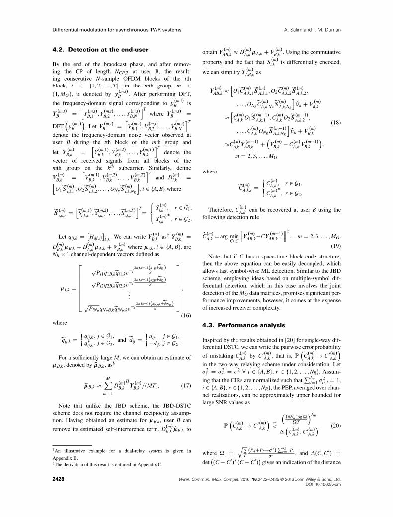
In Figure 3, we compare the BER performance of theJBD detector with that of the coherent detector. Clearly,the coherent scheme outperforms the differential schemeby almost 3 dB which is an expected result. We also plotthe performance of a genie-aided differential detector thatassumes the knowledge of �1,k and �2,k 8k, at user B andthe knowledge of �1,k and �2,k 8k, at user A, and hence self-interference is perfectly removed. As seen in Figure 3, if 15blocks are assumed, the performances of the two schemesmatch closely, which shows the accuracy of the parametersestimation. Furthermore, it shows that our proposed JBDscheme still performs close to the genie-aided case even ifthe number of blocks is reduced from 15 to 10.
Figure 4 compares the JBD-DSTC detector with MG D
150 to the detectors performing coherent DSTC and
Figure 3. Bit error rate (BER) performance of the joint blind-differential (JBD) detector and the coherent detector. SNR,
signal-to-noise ratio.
Figure 4. Bit error rate performance of the joint blind-differential(JBD)- distributed space–time coding (DSTC) detector and the
coherent DSTC detector.
Figure 5. Bit error rate (BER) performance of the proposedschemes and some existing schemes (M D 200). DSTC, dis-tributed space–time coding; JBD, joint blind-differential; SNR,
signal-to-noise ratio.
genie-aided differential DSTC. The latter assumes that thechannels corresponding to the self-interference are knownfor each user, and hence the self-interference is perfectlyremoved. The results show the accuracy of the proposedscheme as it approaches the performance of the genie-aided system. Also, similar to the JBD scheme, the JBD-DSTC scheme has around a 3 dB loss compared withcoherent DSTC.
In Figure 5, we compare our proposed schemes withtwo existing differential-based TWR schemes along withthe conventional single-way relay (SWR) implementationwhen the channel is quasi-static. For SWR implementation,four phases of transmission are required, and hence we useQuadrature PSK rather than BPSK as in the TWR schemesto unify the transmission rate. For the two schemes in [8,9],we properly extend their proposals to the multicarrier caseto perform the comparison. Clearly, the JBD scheme out-performs the JBD-DSTC scheme for SNR values below
Wirel. Commun. Mob. Comput. 2016; 16:2422–2435 © 2016 John Wiley & Sons, Ltd. 2429DOI: 10.1002/wcm
Differential modulation for asynchronous TWR systems A. Salim and T. M. Duman
17 dB for this example, while the opposite happens forhigher SNR values as JBD-DSTC approaches the fulldiversity order of 2. In fact, the JBD-DSTC scheme out-performs all the other considered schemes for SNR valuesabove 25 dB. Specifically, it outperforms the scheme in[9], the one in [8], the JBD scheme and the SWR systemby about 1.5 dB, 1.7 dB, 8.2 dB, and 11.3 dB, respectively,at a BER of about 10�4. Specifically, we attribute theimprovement over the scheme in [9], which is also based ondifferential DSTC, to the fact that the detector in [9] usesestimates of the partner’s previous symbol (in addition tothe currently received signal) to detect the partner’s currentsymbol, which causes error propagation. In our scheme,on the other hand, the detection of the current symbol isindependent from the previous symbol.
We can note from Figure 5 that the scheme in [8]which is based on relay selection diversity performs bet-ter than all other proposals for SNR values below 25 dBfor this example. However, it imposes a transmission over-head as it requires sending a sufficient number of pilotsymbols to aid in assigning specific subcarrier(s) to eachrelay, and after that, additional feedback is required tobroadcast the indices of the subcarriers that each relayshould handle. Furthermore, unlike our schemes whichonly requires simple operations such as complex conju-gation and time-reversal at the relays, the scheme in [8]require the relays to perform DFT and IDFT to enable fil-tering out all subcarriers except the ones assigned to eachone of them.
To quantify this difference, let us compare the timecomplexity of the (major) operations required at the relayfor the two schemes. For the proposed schemes, the timereversal operation corresponds to swapping elements of anarray from one end to the other, hence this algorithm hastime complexity O.N/, and as conjugation is performedin a symbol-wise manner, it has a time complexity O.N/.Therefore, the relay processing of the proposed schemeshas time complexity O.2N/. On the other hand, for thescheme in [8], assuming that the DFT is efficiently com-puted using the fast Fourier transform algorithm whichhas a complexity of O.N log2 N/, then the relay process-ing (DFT and IDFT) has time complexity O.2N log2 N/.This clearly shows the that the complexity of the proposedschemes is much less than that of the scheme in [8] forpractical values of N.
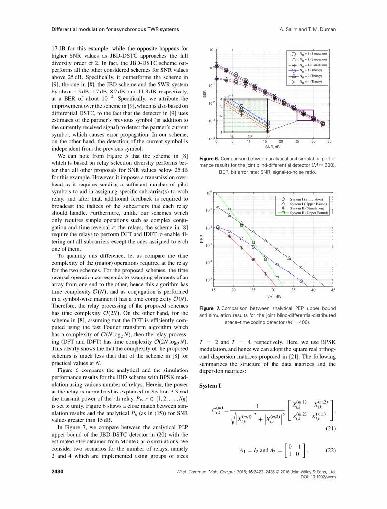
Figure 6 compares the analytical and the simulationperformance results for the JBD scheme with BPSK mod-ulation using various number of relays. Herein, the powerat the relay is normalized as explained in Section 3.3 andthe transmit power of the rth relay, Pr, r 2 f1, 2, : : : , NRg
is set to unity. Figure 6 shows a close match between sim-ulation results and the analytical Pb (as in (15)) for SNRvalues greater than 15 dB.
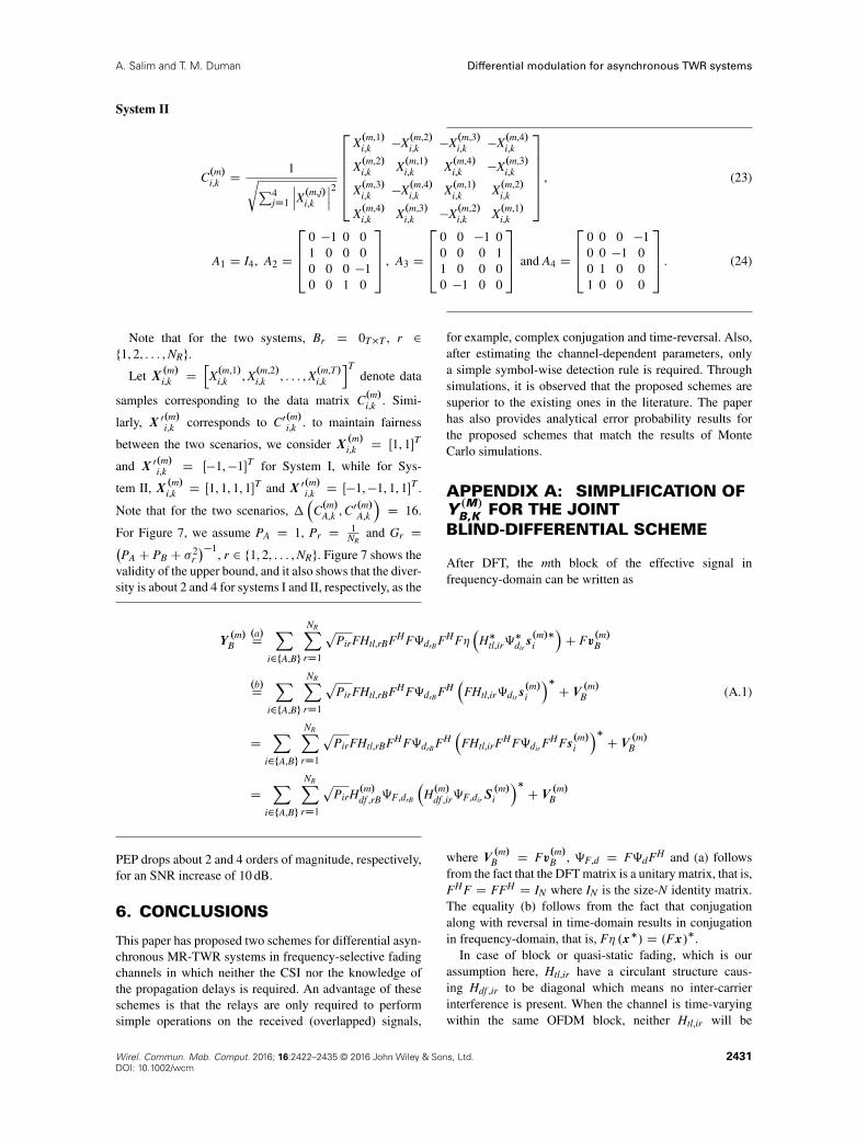
In Figure 7, we compare between the analytical PEPupper bound of the JBD-DSTC detector in (20) with theestimated PEP obtained from Monte Carlo simulations. Weconsider two scenarios for the number of relays, namely2 and 4 which are implemented using groups of sizes
Figure 6. Comparison between analytical and simulation perfor-mance results for the joint blind-differential detector (M D 200).
BER, bit error rate; SNR, signal-to-noise ratio.
Figure 7. Comparison between analytical PEP upper boundand simulation results for the joint blind-differential-distributed
space–time coding detector (M D 400).
T D 2 and T D 4, respectively. Here, we use BPSKmodulation, and hence we can adopt the square real orthog-onal dispersion matrices proposed in [21]. The followingsummarizes the structure of the data matrices and thedispersion matrices:
System I
C.m/i,k D1rˇ̌̌
X.m,1/i,k
ˇ̌̌2Cˇ̌̌X.m,2/
i,k
ˇ̌̌224 X.m,1/
i,k �X.m,2/i,k
X.m,2/i,k X.m,1/
i,k
35 ,
(21)
A1 D I2 and A2 D
�0 �11 0
. (22)
2430 Wirel. Commun. Mob. Comput. 2016; 16:2422–2435 © 2016 John Wiley & Sons, Ltd.DOI: 10.1002/wcm
A. Salim and T. M. Duman Differential modulation for asynchronous TWR systems
System II
C.m/i,k D1rP4
jD1
ˇ̌̌X.m,j/
i,k
ˇ̌̌22666664
X.m,1/i,k �X.m,2/
i,k �X.m,3/i,k �X.m,4/
i,k
X.m,2/i,k X.m,1/
i,k X.m,4/i,k �X.m,3/
i,k
X.m,3/i,k �X.m,4/
i,k X.m,1/i,k X.m,2/
i,k
X.m,4/i,k X.m,3/
i,k �X.m,2/i,k X.m,1/
i,k
3777775 , (23)
A1 D I4, A2 D
26640 �1 0 01 0 0 00 0 0 �10 0 1 0
3775 , A3 D
26640 0 �1 00 0 0 11 0 0 00 �1 0 0
3775 and A4 D
26640 0 0 �10 0 �1 00 1 0 01 0 0 0
3775 . (24)
Note that for the two systems, Br D 0T�T , r 2f1, 2, : : : , NRg.
Let X .m/i,k DhX.m,1/
i,k , X.m,2/i,k , : : : , X.m,T/
i,k
iTdenote data
samples corresponding to the data matrix C.m/i,k . Simi-
larly, X 0.m/i,k corresponds to C0.m/i,k . to maintain fairness
between the two scenarios, we consider X .m/i,k D Œ1, 1�T
and X 0.m/i,k D Œ�1,�1�T for System I, while for Sys-
tem II, X .m/i,k D Œ1, 1, 1, 1�T and X 0.m/i,k D Œ�1,�1, 1, 1�T .
Note that for the two scenarios, �
C.m/A,k , C0.m/A,k
�D 16.
For Figure 7, we assume PA D 1, Pr D1
NRand Gr D�
PA C PB C �2r
��1, r 2 f1, 2, : : : , NRg. Figure 7 shows the
validity of the upper bound, and it also shows that the diver-sity is about 2 and 4 for systems I and II, respectively, as the
PEP drops about 2 and 4 orders of magnitude, respectively,for an SNR increase of 10 dB.
6. CONCLUSIONS
This paper has proposed two schemes for differential asyn-chronous MR-TWR systems in frequency-selective fadingchannels in which neither the CSI nor the knowledge ofthe propagation delays is required. An advantage of theseschemes is that the relays are only required to performsimple operations on the received (overlapped) signals,
for example, complex conjugation and time-reversal. Also,after estimating the channel-dependent parameters, onlya simple symbol-wise detection rule is required. Throughsimulations, it is observed that the proposed schemes aresuperior to the existing ones in the literature. The paperhas also provides analytical error probability results forthe proposed schemes that match the results of MonteCarlo simulations.
APPENDIX A: SIMPLIFICATION OFY .M/
B,K FOR THE JOINTBLIND-DIFFERENTIAL SCHEME
After DFT, the mth block of the effective signal infrequency-domain can be written as
Y.m/B
.a/D
Xi2fA,Bg
NRXrD1
pPirFHtl,rBFHF‰drB FHF�
�H�tl,ir‰
�dirs.m/�i
�C Fv.m/B
.b/D
Xi2fA,Bg
NRXrD1
pPirFHtl,rBFHF‰drB FH
�FHtl,ir‰dirs
.m/i
��C V
.m/B (A.1)
DX
i2fA,Bg
NRXrD1
pPirFHtl,rBFHF‰drB FH
�FHtl,irFHF‰dir F
HFs.m/i
��C V
.m/B
DX
i2fA,Bg
NRXrD1
pPirH.m/df ,rB‰F,drB
�H.m/df ,ir‰F,dirS
.m/i
��C V
.m/B
where V .m/B D Fv.m/B , ‰F,d D F‰dFH and (a) followsfrom the fact that the DFT matrix is a unitary matrix, that is,FHF D FFH D IN where IN is the size-N identity matrix.The equality (b) follows from the fact that conjugationalong with reversal in time-domain results in conjugationin frequency-domain, that is, F� .x�/ D .Fx/�.
In case of block or quasi-static fading, which is ourassumption here, Htl,ir have a circulant structure caus-ing Hdf ,ir to be diagonal which means no inter-carrierinterference is present. When the channel is time-varyingwithin the same OFDM block, neither Htl,ir will be
Wirel. Commun. Mob. Comput. 2016; 16:2422–2435 © 2016 John Wiley & Sons, Ltd. 2431DOI: 10.1002/wcm
Differential modulation for asynchronous TWR systems A. Salim and T. M. Duman
circulant nor will Hdf ,ir be diagonal, which means that thesubcarrier orthogonality is lost, giving rise to inter-carrierinterference. It is clear to see that because of the differenttime delays experienced by the components of the signalin (3.2), different circular shifts resulted. As having a delayof n samples in the time domain causes the kth subcarrierto have a phase shift of e�j2�n.k�1/=N , k 2 f1, 2, : : : , Ng,we can write the received signal on the kth subcarrier as
Y.m/B,k DX
i2fA,Bg
NRXrD1
pPir
hH.m/df ,rB
ik,k
�hH.m/df ,ir
i�k,k
e�j2�.k�1/.drB�dir/
N S.m/i,k
�C V.m/B,k ,
As we assumed the channels to be reciprocal, then for alli 2 fA, Bg, r 2 f1, 2g, Hdf ,ir D Hdf ,ri. We also assume thatdri D dir, r 2 f1, 2g, i 2 fA, Bg. Therefore, the receivedsignal on the kth subcarrier during the mth block can be
written as Y.m/B,k D �kS.m/B,k
�C �kS.m/A,k
�C V.m/B,k .
APPENDIX B: ILLUSTRATIVEEXAMPLE FOR THE JOINTBLIND-DIFFERENTIAL-DISTRIBUTEDSPACE–TIME CODING SCHEME:DUAL-RELAY CASE
To clearly illustrate the resulting DSTC structure, we con-sider the case of having two relays (NR D 2) and usingtwo blocks per group (T D 2). For this case, we adoptthe dispersion matrices design in [20] that results in Alam-outi’s code structure. Specifically, the relays’ matrices arechosen as
A1 D
�1 00 1
, B1 D 0T�T ,
A2 D 0T�T and B2 D
�0 �11 0
.
(B.1)
Interestingly, for the case of NR D 2 and T D 2, it wasfound in [20] that a space–time codeword, C, satisfies thecommutative property if and only if it follows the 2 � 2
Alamouti structure. Hence, C.m/i,k is constructed as
C.m/i,k D1rˇ̌̌
X.m,1/i,k
ˇ̌̌2Cˇ̌̌X.m,2/
i,k
ˇ̌̌224 X.m,1/
i,k �X.m,2/i,k
�
X.m,2/i,k X.m,1/
i,k
�
35 .
(B.2)
After removing the CP of length NCP,2 at user B, theresulting two consecutive N-sample OFDM blocks of themth group, m 2 f1, MGg, can be written as
y.m,1/B D
pPA1Htl,1B‰d1B Htl,A1‰dA1s
.m,1/A �
pPA2Htl,2B‰d2B�
�H�tl,A2‰
�dA2s.m,2/�A
�Cp
PB1Htl,1B‰d1B Htl,B1‰dB1s.m,1/B �
pPB2Htl,2B‰d2B�
�H�tl,B2‰
�dB2s.m,2/�B
�C v
.m,1/B ,
(B.3)
y.m,2/B D
pPA1Htl,1B‰d1B Htl,A1‰dA1s
.m,2/A C
pPA2Htl,2B‰d2B�
�H�tl,A2‰
�dA2s.m,1/�A
�Cp
PB1Htl,1B‰d1B Htl,B1‰dB1s.m,2/B C
pPB2Htl,2B‰d2B�
�H�tl,B2‰
�dB2s.m,1/�B
�C v
.m,2/B ,
(B.4)
where v.m,t/B represents length-N effective noise vector at
user B during the tth block of the mth group whose entriesare AWGN random variables with zero mean and varianceof �2
B.After performing DFT, the frequency-domain signal cor-
responding to the first block of the mth group can bewritten as
Y.m,1/B Dp
PA1FHtl,1BFHF‰d1B FHFHtl,A1FHF‰dA1s.m,1/A
�p
PA2FHtl,2BFHF‰d2B FHF��H�tl,A2‰
�dA2s.m,2/�A
�Cp
PB1FHtl,1BFHF‰d1BFHFHtl,B1F
HF‰dB1FHFs.m,1/
B
�p
PB2FHtl,2BFHF‰d2B FHF�
��
H�tl,B2‰�dB2s.m,2/�B
�C V
.m,1/B
Dp
PA1Hdf ,1B‰F,d1B Hdf ,A1‰F,dA1S.m,1/A
�p
PA2Hdf ,2B‰F,d2B
�Hdf ,A2‰F,dA2S
.m,2/A
��Cp
PB1Hdf ,1B‰F,d1B Hdf ,B1‰F,dB1S.m,1/B
�p
PB2Hdf ,2B‰F,d2B
�Hdf ,B2‰F,dB2S
.m,2/B
��C V
.m,1/B
(B.5)
where V .m,t/B D Fv.m,t/
B . Similarly, we can write Y .m,2/B for
the second block as
Y.m,2/B D
pPA1Hdf ,1B‰F,d1B Hdf ,A1‰F,dA1S
.m,2/A
Cp
PA2Hdf ,2B‰F,d2B
�Hdf ,A2‰F,dA2S
.m,1/A
��Cp
PB1Hdf ,1B‰F,d1B Hdf ,B1‰F,dB1S.m,2/B
Cp
PB2Hdf ,2B‰F,d2B
�Hdf ,B2‰F,dB2S
.m,1/B
��C V
.m,2/B .
(B.6)
2432 Wirel. Commun. Mob. Comput. 2016; 16:2422–2435 © 2016 John Wiley & Sons, Ltd.DOI: 10.1002/wcm
A. Salim and T. M. Duman Differential modulation for asynchronous TWR systems
With Y.m/B,k D
hY.m,1/
B,k , Y.m,2/B,k
iTand V
.m/B,k Dh
V.m,1/B,k , V.m,2/
B,k
iT, we can write Y .m/B,k as
Y.m/B,k D D.m/B,k �B,k C D.m/A,k �A,k C V
.m/B,k , (B.7)
where
D.m/i,k D
24 S.m,1/i,k �S.m,2/
i,k
�
S.m,2/i,k S.m,1/
i,k
�
35 , i 2 fA, Bg, (B.8)
�.m/B,k D
264p
PB1
hH.m/df ,1B
ik,k
hH.m/df ,B1
ik,k
e�j2�.k�1/.d1BCdB1/
N
pPB2
hH.m/df ,2B
ik,k
hH.m/df ,B2
i�k,k
e�j2�.k�1/.d2B�dB2/
N
375 ,
(B.9)and
�.m/A,k D
264p
PA1
hH.m/df ,1B
ik,k
hH.m/df ,A1
ik,k
e�j2�.k�1/.d1BCdA1/
N
pPA2
hH.m/df ,2B
ik,k
hH.m/df ,A2
i�k,k
e�j2�.k�1/.d2B�dA2/
N
375 .
(B.10)
APPENDIX C: ESTIMATION OF THESELF-INTERFERENCE TERM IN THEJBD-DSTC SCHEME
As a first step we investigate the expected value
of D.m/B,k
HY.m/B,k over the constellation points of S.m/A,k
and S.m/B,k . We can write this as E
�D.m/B,k
HY.m/B,k
D
E
�D.m/B,k
HD.m/B,k
�B,k C E
�D.m/B,k
HD.m/A,k
�A,k C V
.m/B,k .
To simplify exposition, and because we aim totake the expectation over the constellation pointsrather than time or frequency, we will drop the sub-carrier index (k) and the block index (m) such that
D.m/i,k , eS .m/i,k,r and eS.m,t/i,k,r will be expressed by Di,eS i,r and eS.t/i,r , respectively. We can write DB
HDB as
DBHDB D
266664eSH
B,1OH1 O1eSB,1
eSHB,1OH
1 O2eSB,2 : : :eSH
B,1OH1 ONR
eSB,NReSHB,2OH
2 O1eSB,1eSH
B,2OH2 O2eSB,2 : : :
eSHB,2OH
2 ONReSB,NR
......
. . ....eSH
B,NROH
NRO1eSB,1 : : : : : : eSH
B,NROH
NRONR
eSB,NR
377775 , (C.1)
D
266664T eSH
B,1OH1 O2eSB,2 : : :
eSHB,1OH
1 ONReSB,NReSH
B,2OH2 O1eSB,1 T : : : eSH
B,2OH2 ONR
eSB,NR
......
. . ....eSH
B,NROH
NRO1eSB,1 : : : : : : T
377775 , (C.2)
where we used the fact OHr Or D IT . Let Ji,j D OH
i Oj
and let its element in the .l, p/ position be denoted by Ji,jl,p.
Recall that Ji,j, i ¤ j, is a hollow matrix, that is, Ji,jl,l D 0
8l 2 f1, 2, : : : , Tg.
Note that eSHB,iJ
i,jeSB,j DPT
rD1eS.r/B,i
�PTcD1 Ji,j
r,ceS.c/B,j DPTrD1
PTcD1 Ji,j
r,ceS.r/B,i
�eS.c/B,j . Hence, we can write
EheSH
B,iJi,jeSB,j
iDPT
rD1PT
cD1 Ji,jr,cE
heS.r/B,i
�eS.c/B,j
i. Due to
the differential encoding, botheS.r/B,i andeS.c/B,j are correlatedbecause they both consist of differently-weighted linearcombination of the same T random variables, which on theother hand, are also correlated with each other because ofthe same reason. However, by examining their correlationcoefficients, we have found that they are small enough tobe neglected. Therefore, we approximate their correlation
by zero, and hence EheSH
B,iJi,jeSB,j
i� 0, i ¤ j, and
E�DB
HDB�� TINR . Following the same rationale, we
conclude that E�DB
HDA�� 0NR�NR .
Finally, assuming large M, we use the law of large
numbers to approximate the expected value of D.m/B,k
HY.m/B,k
by its time average, which can be calculated at user B,
asPM
mD1 D.m/B,k
HY.m/B,k =M, and hence we obtain b�B,k �PM
mD1 D.m/B,k
HY.m/B,k =.MT/ for large SNRs.
ACKNOWLEDGEMENTS
This work was supported by the National Science Founda-tion under the grants NSF-CCF 1117174 and NSF-ECCS1102357 and by the European Commission under the grantMC-CIG PCIG12-GA-2012-334213.
REFERENCES
1. Salim A, Duman TM. An asynchronous two-way relaysystem with full delay diversity in time-varying mul-tipath environments. In IEEE International Confer-ence on Computing, Networking and Communications(ICNC), Feb. 2015; 900–904.
Wirel. Commun. Mob. Comput. 2016; 16:2422–2435 © 2016 John Wiley & Sons, Ltd. 2433DOI: 10.1002/wcm
Differential modulation for asynchronous TWR systems A. Salim and T. M. Duman
2. Salim A, Duman TM. A delay-tolerant asynchronoustwo-way-relay system over doubly-selective fadingchannels. IEEE Transactions on Wireless Communica-tions 2015; 14(7): 3850–3865.
3. Song L, Li Y, Huang A, Jiao B, Vasilakos A. Dif-ferential modulation for bidirectional relaying withanalog network coding. IEEE Transactions on SignalProcessing 2010; 58(7): 3933–3938.
4. Cui T, Gao F, Tellambura C. Differential modulationfor two-way wireless communications: a perspectiveof differential network coding at the physical layer.IEEE Transactions on Communications 2009; 57(10):2977–2987.
5. Guan W, Liu K. Performance analysis of two-wayrelaying with non-coherent differential modulation.IEEE Transactions on Wireless Communications 2011;10(6): 2004–2014.
6. Zhu K, Burr A. A simple non-coherent physical-layer network coding for transmissions over two-wayrelay channels. In IEEE Global Communications Con-ference (GLOBECOM), Anaheim, California, 2012;2268–2273.
7. Bhatnagar MR. Making two-way satellite relayingfeasible: a differential modulation based approach.IEEE Transactions on Communications 2015; 63 (8):2836–2847.
8. Song L, Hong G, Jiao B, Debbah M. Joint relayselection and analog network coding using differ-ential modulation in two-way relay channels. IEEETransactions on Vehicular Technology 2010; 59 (6):2932–2939.
9. Utkovski Z, Yammine G, Lindner J. A distributed dif-ferential space-time coding scheme for two-way wire-less relay networks. In IEEE International Symposiumon Information Theory, Seoul, Korea, 2009; 779–783.
10. Huo Q, Song L, Li Y, Jiao B. A distributed differentialspace-time coding scheme with analog network cod-ing in two-way relay networks. IEEE Transactions onSignal Processing 2012; 60(9): 4998–5004.
11. Alabed S, Pesavento M, Klein A. Distributed differ-ential space-time coding for two-way relay networksusing analog network coding. In the 21st European Sig-nal Processing Conference (EUSIPCO), Marrakech,Morocco, 2013; 1–5.
12. Wu Z, Liu L, Jin Y, Song L. Signal detection fordifferential bidirectional relaying with analog networkcoding under imperfect synchronisation. IEEE Com-munications Letters 2013; 17(6): 1132–1135.
13. Qian M, Jin Y, Wu Z, Wang T. Asynchronous two-wayrelaying networks using distributed differential space-time coding. International Journal of Antennas andPropagation 2015; 2015: 9 pages, Article ID 563737.
14. Avendi MR, Jafarkhani H. Differential distributedspace–time coding with imperfect synchronization infrequency-selective channels. IEEE Transactions on
Wireless Communications 2015; 14(4): 1811–1822.15. Fang Z, Zheng L, Wang L, Jin L. A frequency domain
differential modulation scheme for asynchronousamplify-and-forward relay networks. In IEEE China
Summit and International Conference on Signal and
Information Processing (ChinaSIP), Chengdu, China,July 2015; 977–981.
16. Wei R-Y. Differential encoding for quadrature-amplitude modulation. In IEEE Vehicular Technology
Conference (VTC), Ottawa, Canada, May 2010; 1–5.17. Divsalar D, Simon MK. Multiple-symbol differential
detection of mpsk. IEEE Transactions on Communica-
tions 1990; 38(3): 300–308.18. Hasna M, Alouini M-S. End-to-end performance of
transmission systems with relays over Rayleigh-fadingchannels. IEEE Transactions on Wireless Communica-
tions 2003; 2(6): 1126–1131.19. Jing Y, Hassibi B. Distributed space-time coding in
wireless relay networks. IEEE Transactions on Wire-
less Communications 2006; 5(12): 3524–3536.20. Jing Y, Jafarkhani H. Distributed differential space-
time coding for wireless relay networks. IEEE Trans-
actions on Communications 2008; 56(7): 1092–1100.21. Tarokh V, Jafarkhani H, Calderbank A. Space-
time block codes from orthogonal designs. IEEE
Transactions on Information Theory 1999; 45(5):1456–1467.
AUTHORS’ BIOGRAPHIES
Ahmad Salim is a Post-DoctoralResearch Associate in the Departmentof Electrical and Computer Engineer-ing at the University of Illinois atChicago, Illinois, USA. He receivedhis BS degree in Electrical Engineeringfrom the University of Jordan, Amman,Jordan, in 2006. Later, he received his
MS in Telecommunication Engineering from King FahdUniversity of Petroleum and Minerals, Dhahran, SaudiArabia, in 2010. In 2015, he received his PhD in ElectricalEngineering from Arizona State University, Arizona, USA.Broadly speaking, his research belongs to the areas ofcommunications theory, information theory and signal pro-cessing, including wireless communications, underwateracoustic communications, cooperative communications,MIMO systems, diversity techniques, error control cod-ing, and iterative receivers. Dr. Salim achieved the eighthplace in Jordan’s 2006 nationwide comprehensive exam-ination in the Electrical Engineering discipline. He is anactive participant of the Sensor, Signal and Information
2434 Wirel. Commun. Mob. Comput. 2016; 16:2422–2435 © 2016 John Wiley & Sons, Ltd.DOI: 10.1002/wcm
A. Salim and T. M. Duman Differential modulation for asynchronous TWR systems
Processing (SenSIP) Center of Arizona State University.He served as a reviewer for IEEE Transactions on WirelessCommunications, IEEE Wireless Communications Letters,IEEE Transactions on Vehicular Technology, and ElsevierPhysical Communication among others. He is a member ofthe Communication Theory Technical Committee.
Tolga M. Duman is a Professor ofElectrical and Electronics Engineer-ing Department of Bilkent Universityin Turkey, and an adjunct professorwith the School of ECEE at ArizonaState University. He received the BSdegree from Bilkent University inTurkey in 1993, MS and PhD degrees
from Northeastern University, Boston, in 1995 and 1998,respectively, all in electrical engineering. Prior to joiningBilkent University in September 2012, he has been with the
Electrical Engineering Department of Arizona State Uni-versity first as an Assistant Professor (1998–2004),as an Associate Professor (2004–2008), and as a Profes-sor (2008–2015). Dr. Duman’s current research interestsare in systems, with particular focus on communica-tion and signal processing, including wireless and mobilecommunications, coding/modulation, coding for wirelesscommunications, data storage systems and underwateracoustic communications. Dr. Duman is a Fellow of IEEE,a recipient of the National Science Foundation CAREERAward and IEEE Third Millennium medal. He served asan editor for IEEE Trans. on Wireless Communications(2003–2008), IEEE Trans. on Communications (2007–2012), and IEEE Online Journal of Surveys and Tutorials(2002–2007). He is currently the coding and communica-tion theory area editor for IEEE Trans. on Communications(2011–present) and an editor for Elsevier Physical Com-munications Journal (2010–present).
Wirel. Commun. Mob. Comput. 2016; 16:2422–2435 © 2016 John Wiley & Sons, Ltd. 2435DOI: 10.1002/wcm


![Asynchronous Transfer Mode (ATM) FundamentalsX.25, frame relay, transmission control protocol [TCP]/Internet protocol [IP], ATM integrates the multiplexing and switching functions,](https://img.pdfslide.us/doc/110x75/5f0cea497e708231d437c2ad/asynchronous-transfer-mode-atm-fundamentals-x25-frame-relay-transmission-control.jpg)