Embed Size (px)
Citation preview
8/9/2019 Diethyl Ether Plant
http://slidepdf.com/reader/full/diethyl-ether-plant 1/21
ChE 455
Fall 2011
Major 1
Problems at the Ether Plant
Background
Diethyl ether (DEE) is a colorless, highly volatile, flammable liquid with a characteristic
odor. It is an important solvent in the production of cellulose acetate and other cellulose-based plastics. Other uses for DEE are as a starter fluid for diesel and gasoline engines, as a solvent for
Grignard and other reactions involving organometallic reagents, and, previously, it was used as a
general anesthetic.
The common production method for DEE is as a by-product from the vapor-phase hydration
of ethylene to make ethanol. However, the client who has employed your company to design
this process has an excess of ethanol in their facility. Therefore, the process of interest in thisassignment uses the vapor-phase dehydration of ethanol.
Immediate Problem
The client contracted our company to design and build a plant to produce 50,000 tonne/y of
99.5+% grade DEE. We had no experience in designing a DEE facility, so we used a previousdesign for a similar (but different) product as a starting point for the new facility. The plant has
been designed, specified, and orders for major equipment have been placed. Recently, a technical
expert was brought into the company for consulting on an unrelated issue. While she was
consulting on this other job, a manager asked her if she would take a quick look at the design ofthe ether plant. She observed that the UNIFAC VLE model used in the process simulation was
not suitable for predicting the DEE-H2O azeotrope (The azeotropic behavior of DEE-water
mixtures is given in Appendix 2) and thought that there might be a problem with the design. Sheindicated that the NRTL model would give more accurate results. This information was raised at
a recent management meeting and has caused your boss a lot of anguish!
The equipment has been ordered and the manufacturers insist that it is too late to change the
orders for the equipment. Therefore, we are facing a serious problem in that if any process
changes are needed because of a faulty design, then our company, and not our client, will have to
pay for them. Moreover, if there is a significant delay in completing construction because of newequipment being ordered and increases in operating costs, we may have to compensate the client.
Needless to say, lawyers from both sides are currently in negotiation.
Assignment
Using the information in this document and the Chemcad simulation provided, your team isto evaluate the consequences of correcting the design using the appropriate VLE package. Your
first step should be to identify the correct thermodynamic package (K -value model), namely, that
8/9/2019 Diethyl Ether Plant
http://slidepdf.com/reader/full/diethyl-ether-plant 2/21
2
the package chosen predicts the formation of an azeotrope at the conditions listed above. The
SRK enthalpy model is appropriate for the enthalpy calculations in this process.
Once the correct K -value model has been chosen, the process must be evaluated and
corrected so that the process, using the correct K -value model, produces the required amount of
DEE at the required purity (50,000 tonne/y at 99.5+ mol % purity). You should identify how theexisting equipment can be best utilized and what, if any, new equipment must be purchased. The
new operating cost for the corrected plant configuration should be evaluated and compared to the
operating cost for the current (incorrect) design. The difference between these costs will be usedas part of the negotiation for damages between the client and our company. It should be clear
that if the operating expenses for your new design are greater than for the old (incorrect) design
then the client will argue that our company should be responsible for paying the difference. Forcapital equipment expenditures, use a before-tax interest rate of 15% over 10 years.
Process Description
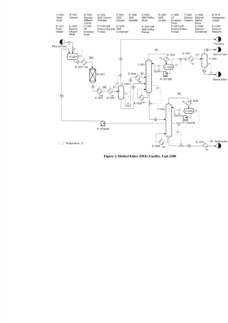
The process flow diagram is shown in Figure 1. The reactions, the kinetics, and theequilibrium equations are detailed in Appendix 1.
The fresh feed to the unit, Stream 1, consists of 70 mol% ethanol in water with a trace
amount of methanol. This stream is pumped from storage and sent to an on-site feed vessel, V-
1201, where it is mixed with recycled ethanol, Stream 11. The stream leaving V-1201, Stream 2,
is vaporized and heated to 200°C in heat exchanger E-1201. It is then fed to the packed bed
reactor, R-1201. The reactor contains a packed bed of “alumina” catalyst that operatesadiabatically. The desired reaction is slightly exothermic and the exotherm across the reactor is
~60°C. The reactor effluent, Stream 3, is cooled in E-1202 where low-pressure steam isgenerated. The stream leaving E-1202 is further cooled in E-1203 using cooling water and enters
the high-pressure knock-out drum, V-1202, at 37°C. The overhead stream from V-1201, Stream4, contains most of the ethylene that is formed in an undesirable side reaction along with small
amounts of DEE and ethanol. This stream is sent to another process as fuel gas.
The liquid in V-1202 forms two phases, the lighter liquid stream from the knockout drum,
Stream 5, is heated to 80°C in E-1204 using low-pressure steam. The exit stream from E-1204,
enters the DEE purification column, T-1201. The heavier liquid stream, Stream 6, is also fed toT-1201 where the DEE is separated from the water and ethanol. It should be noted that since thefeed to T-1201 contains small amounts of ethylene a partial condenser is used. The overhead
product from this column is then cooled and condensed in E-1207 and is then fed to the low-
pressure knock-out drum, V-1204. The overhead stream from V-1204, Stream 9, is vented to
flare and the liquid product, Stream 10, is the DEE 99.5+% product stream that is sent to storagewhere a peroxide inhibitor is added.
The bottom product from T-1201, Stream 8, is sent to a second column, T-1202, where theethanol is purified as the top product to a 70 mol% pure aqueous mixture. This mixture, Stream
11, is pumped back to the feed pressure using P-1203A/B and returned to the front end of the
process. The bottom product stream, Stream 12, is water with trace amounts of organic material
8/9/2019 Diethyl Ether Plant
http://slidepdf.com/reader/full/diethyl-ether-plant 3/21
Figure 1: Diethyl Ether (DEE) Facility, Unit 1200
8/9/2019 Diethyl Ether Plant
http://slidepdf.com/reader/full/diethyl-ether-plant 4/21
4
that is cooled to 40°C in E-1210 and then sent to wastewater treatment prior to discharge to the
environment.
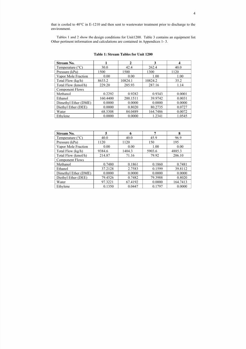
Tables 1 and 2 show the design conditions for Unit1200. Table 3 contains an equipment list.
Other pertinent information and calculations are contained in Appendices 1- 3.
Table 1: Stream Tables for Unit 1200
Stream No. 1 2 3 4
Temperature (°C) 30.0 42.4 262.4 40.0
Pressure (kPa) 1500 1500 1300 1120
Vapor Mole Fraction 0.00 0.00 1.00 1.00
Total Flow (kg/h) 8633.2 10824.1 10824.2 35.2
Total Flow (kmol/h) 229.20 285.93 287.16 1.14
Component Flows
Methanol 0.2292 0.9282 0.9343 0.0001Ethanol 160.4400 200.1511 39.9742 0.0031
Dimethyl Ether (DME) 0.0000 0.0000 0.0000 0.0000
Diethyl Ether (DEE) 0.0000 0.8020 80.2735 0.0727
Water 68.5308 84.0489 164.7486 0.0072
Ethylene 0.0000 0.0000 1.2341 1.0545
Stream No. 5 6 7 8
Temperature (°C) 40.0 40.0 45.9 96.9
Pressure (kPa) 1120 1120 150 195Vapor Mole Fraction 0.00 0.00 1.00 0.00
Total Flow (kg/h) 9384.6 1404.3 5903.6 4885.3
Total Flow (kmol/h) 214.87 71.16 79.92 206.10
Component Flows
Methanol 0.7480 0.1861 0.1860 0.7481
Ethanol 37.2128 2.7583 0.1599 39.8112
Dimethyl Ether (DME) 0.0000 0.0000 0.0000 0.0000
Diethyl Ether (DEE) 79.4526 0.7482 79.3988 0.8020
Water 97.3221 67.4192 0.0000 164.7413
Ethylene 0.1350 0.0447 0.1797 0.0000
8/9/2019 Diethyl Ether Plant
http://slidepdf.com/reader/full/diethyl-ether-plant 5/21
5
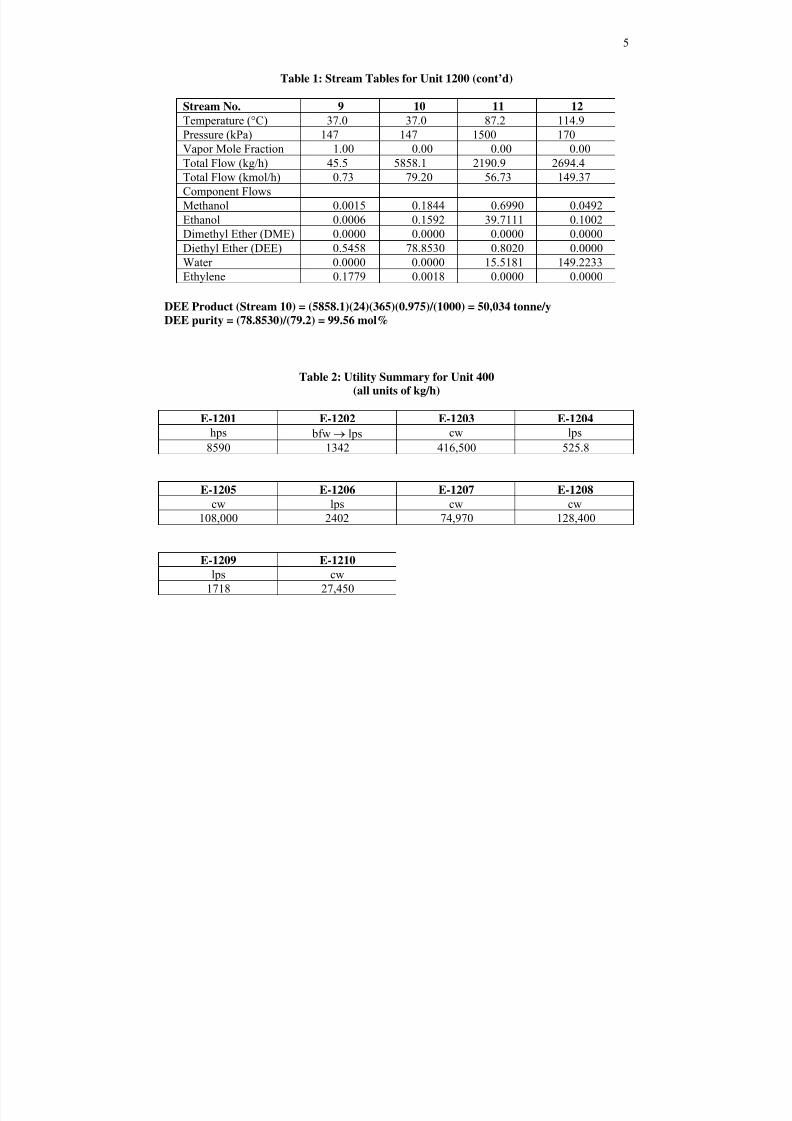
Table 1: Stream Tables for Unit 1200 (cont’d)
Stream No. 9 10 11 12
Temperature (°C) 37.0 37.0 87.2 114.9
Pressure (kPa) 147 147 1500 170
Vapor Mole Fraction 1.00 0.00 0.00 0.00Total Flow (kg/h) 45.5 5858.1 2190.9 2694.4
Total Flow (kmol/h) 0.73 79.20 56.73 149.37
Component Flows
Methanol 0.0015 0.1844 0.6990 0.0492
Ethanol 0.0006 0.1592 39.7111 0.1002
Dimethyl Ether (DME) 0.0000 0.0000 0.0000 0.0000
Diethyl Ether (DEE) 0.5458 78.8530 0.8020 0.0000
Water 0.0000 0.0000 15.5181 149.2233
Ethylene 0.1779 0.0018 0.0000 0.0000
DEE Product (Stream 10) = (5858.1)(24)(365)(0.975)/(1000) = 50,034 tonne/yDEE purity = (78.8530)/(79.2) = 99.56 mol%
Table 2: Utility Summary for Unit 400
(all units of kg/h)
E-1201 E-1202 E-1203 E-1204
hps bfw → lps cw lps
8590 1342 416,500 525.8
E-1205 E-1206 E-1207 E-1208
cw lps cw cw
108,000 2402 74,970 128,400
E-1209 E-1210
lps cw
1718 27,450
8/9/2019 Diethyl Ether Plant
http://slidepdf.com/reader/full/diethyl-ether-plant 6/21
6
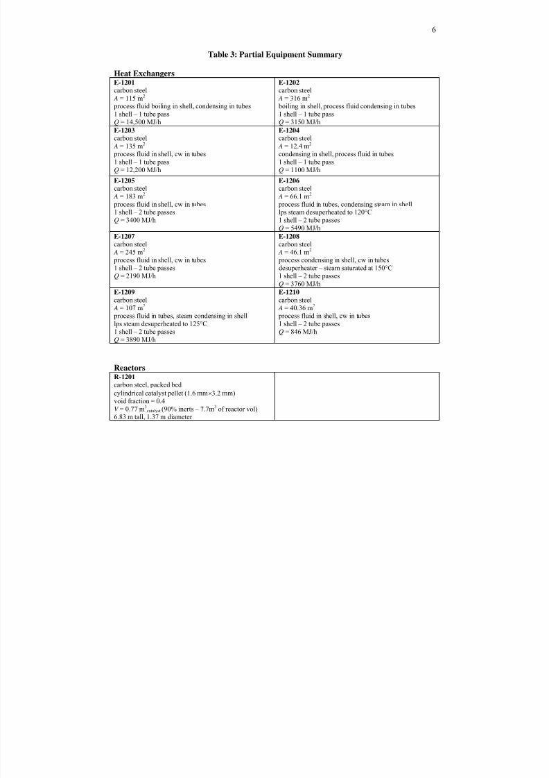
Table 3: Partial Equipment Summary
Heat ExchangersE-1201
carbon steel
A = 115 m2
process fluid boiling in shell, condensing in tubes1 shell – 1 tube pass
Q = 14,500 MJ/h
E-1202
carbon steel
A = 316 m2
boiling in shell, process fluid condensing in tubes1 shell – 1 tube pass
Q = 3150 MJ/h
E-1203
carbon steel
A = 135 m2 process fluid in shell, cw in tubes
1 shell – 1 tube pass
Q = 12,200 MJ/h
E-1204
carbon steel
A = 12.4 m2 condensing in shell, process fluid in tubes
1 shell – 1 tube pass
Q = 1100 MJ/h
E-1205carbon steel
A = 183 m2
process fluid in shell, cw in tubes
1 shell – 2 tube passesQ = 3400 MJ/h
E-1206carbon steel
A = 66.1 m2
process fluid in tubes, condensing steam in shell
lps steam desuperheated to 120°C1 shell – 2 tube passes
Q = 5490 MJ/h
E-1207
carbon steel
A = 245 m2 process fluid in shell, cw in tubes
1 shell – 2 tube passes
Q = 2190 MJ/h
E-1208
carbon steel
A = 46.1 m2 process condensing in shell, cw in tubes
desuperheater – steam saturated at 150°C
1 shell – 2 tube passes
Q = 3760 MJ/h
E-1209
carbon steel
A = 107 m2
process fluid in tubes, steam condensing in shelllps steam desuperheated to 125°C
1 shell – 2 tube passesQ = 3890 MJ/h
E-1210
carbon steel
A = 40.36 m2
process fluid in shell, cw in tubes1 shell – 2 tube passes
Q = 846 MJ/h
ReactorsR-1201
carbon steel, packed bed
cylindrical catalyst pellet (1.6 mm×3.2 mm)
void fraction = 0.4V = 0.77 m3
catalyst (90% inerts – 7.7m3 of reactor vol)6.83 m tall, 1.37 m diameter
8/9/2019 Diethyl Ether Plant
http://slidepdf.com/reader/full/diethyl-ether-plant 7/21
7
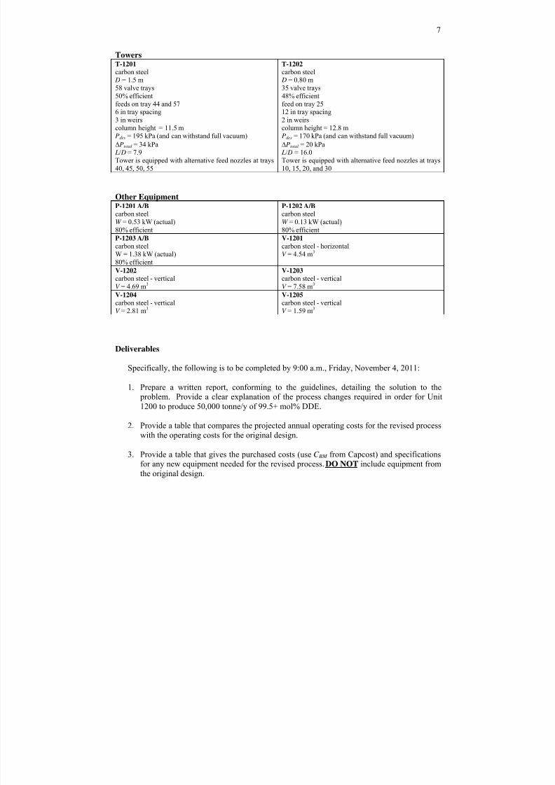
TowersT-1201
carbon steel D = 1.5 m
58 valve trays
50% efficient
feeds on tray 44 and 576 in tray spacing
3 in weirs
column height = 11.5 mPdes = 195 kPa (and can withstand full vacuum)
ΔPtotal = 34 kPa L/ D = 7.9
Tower is equipped with alternative feed nozzles at trays
40, 45, 50, 55
T-1202
carbon steel D = 0.80 m
35 valve trays
48% efficient
feed on tray 2512 in tray spacing
2 in weirs
column height = 12.8 mPdes = 170 kPa (and can withstand full vacuum)
ΔPtotal = 20 kPa L/ D = 16.0
Tower is equipped with alternative feed nozzles at trays
10, 15, 20, and 30
Other EquipmentP-1201 A/B
carbon steelW = 0.53 kW (actual)
80% efficient
P-1202 A/B
carbon steelW = 0.13 kW (actual)
80% efficient
P-1203 A/B
carbon steel
W = 1.38 kW (actual)
80% efficient
V-1201
carbon steel - horizontal
V = 4.54 m3
V-1202
carbon steel - vertical
V = 4.69 m3
V-1203
carbon steel - vertical
V = 7.58 m3
V-1204
carbon steel - vertical
V = 2.81 m3
V-1205
carbon steel - vertical
V = 1.59 m3
Deliverables
Specifically, the following is to be completed by 9:00 a.m., Friday, November 4, 2011:
1. Prepare a written report, conforming to the guidelines, detailing the solution to the problem. Provide a clear explanation of the process changes required in order for Unit
1200 to produce 50,000 tonne/y of 99.5+ mol% DDE.
2.
Provide a table that compares the projected annual operating costs for the revised processwith the operating costs for the original design.
3. Provide a table that gives the purchased costs (use C BM from Capcost) and specificationsfor any new equipment needed for the revised process. DO NOT include equipment from
the original design.
8/9/2019 Diethyl Ether Plant
http://slidepdf.com/reader/full/diethyl-ether-plant 8/21
8
4. Submit a written report, conforming to the guidelines, detailing the information in items 1
and 2, above
5. Include an updated PFD and stream table for the modified process.
6.
Include, in an appendix, a legible, organized set of calculations justifying yourrecommendations, including any assumptions made. In addition, a converged Chemcad
simulation of the proposed design MUST be included in a separate appendix.
7. Include a signed copy of the attached confidentiality statement
Report Format
This report should be brief and should conform to the guidelines, which are available at the
end of the following web page: http://www.che.cemr.wvu.edu/publications/projects/index.php.It should be bound in a 3-ring binder/folder that is not oversized relative to the number of pages
in the report. Figures and tables should be included as appropriate. An appendix must beattached that includes items such as the requested calculations and a Chemcad consolidated
report (required) of the converged simulation for your recommended case. Stream properties(viscosity, density, etc.) ARE NOT to be included in the Chemcad consolidated report, but
stream conditions and components must be included, and there will be a deduction if these rules
are not followed. The calculations in the appendix should be easy to follow. The confidentialitystatement should be the very last page of the report.
The written report is a very important part of the assignment. Reports that do not conform tothe guidelines will receive severe deductions and will have to be rewritten to receive credit.
Poorly written and/or organized written reports may also require re-writing. Be sure to followthe format outlined in the guidelines for written reports.
Oral Presentation
You will be expected to present and defend your results sometime between November 7,
2010 and November 15, 2011. Your presentation should be 15-20 minutes, followed by about a
30-minute question and answer period. Make certain that you prepare for this presentation sinceit is an important part of your assignment. You should bring at least one hard copy of your slides
to the presentation and hand it out before beginning the presentation.
Other Rules
You may not discuss this major with anyone other than the instructors and your partner.Discussion, collaboration, or any interaction with anyone other than the instructor or your partner
is prohibited. This means that any cross talk among students about anything relating to this
assignment, no matter how insignificant it may seem to you, is a violation of the rules and isconsidered academic dishonesty. Violators will be subject to the penalties and procedures
outlined in the University Procedures for Handling Academic Dishonesty Cases (see p. 56 of
8/9/2019 Diethyl Ether Plant
http://slidepdf.com/reader/full/diethyl-ether-plant 9/21
9
20011-12 Undergraduate Catalog (http://coursecatalog.wvu.edu/) or follow the link
http://docs.facultysenate.wvu.edu/08Files/AcademicDishonestyFlowChart.pdf ).
Consulting is available from the instructors. Chemcad consulting, i.e., questions on how to
use Chemcad, not how to interpret results, is unlimited and free, but only from the instructors.
Each team may receive five free minutes of consulting from the instructors. After five minutesof consulting, the rate is 2.5 points deducted for 15 minutes or any fraction of 15 minutes, on a
cumulative basis. The initial 15-minute period includes the 5 minutes of free consulting.
Late Reports
Late reports are unacceptable. The following severe penalties will apply:
• late report on due date before noon: one letter grade (10 points)
• late report after noon on due date: two letter grades (20 points)
• late report one day late: three letter grades (30 points)
• each additional day late: 10 additional points per day
8/9/2019 Diethyl Ether Plant
http://slidepdf.com/reader/full/diethyl-ether-plant 10/21
10
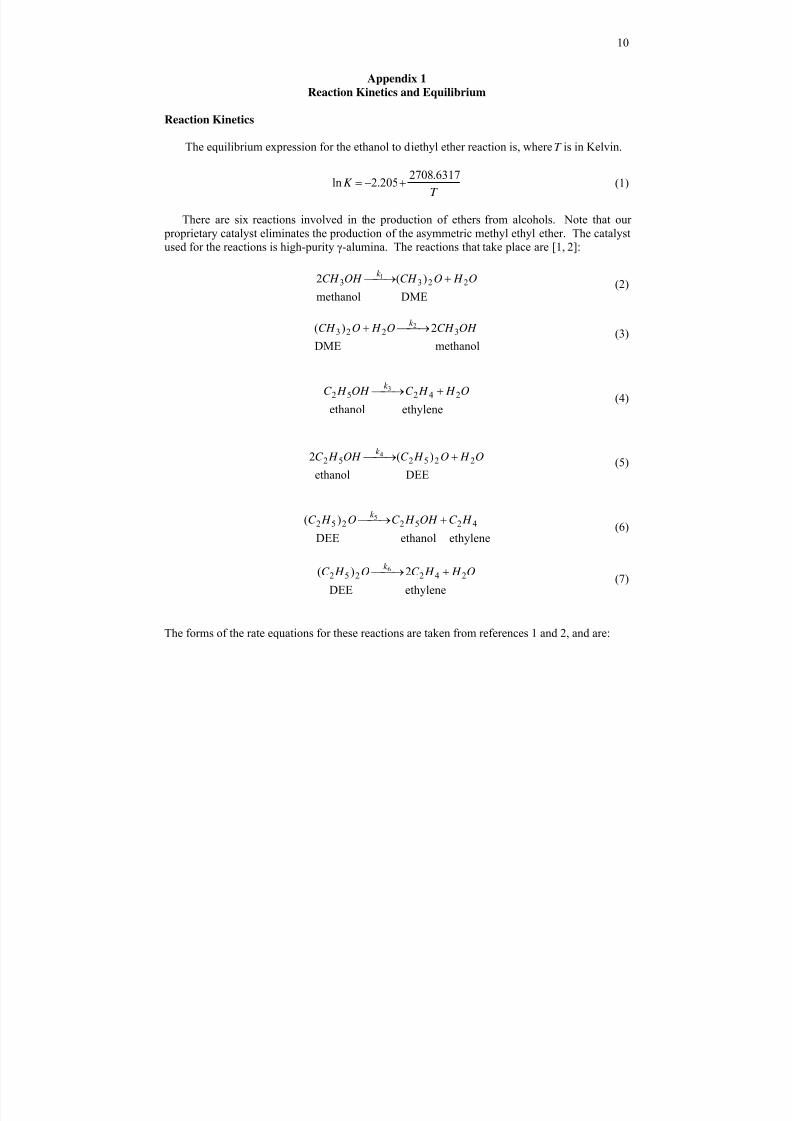
Appendix 1
Reaction Kinetics and Equilibrium
Reaction Kinetics
The equilibrium expression for the ethanol to diethyl ether reaction is, where T is in Kelvin.
T K
6317.2708205.2ln +−= (1)
There are six reactions involved in the production of ethers from alcohols. Note that our
proprietary catalyst eliminates the production of the asymmetric methyl ethyl ether. The catalystused for the reactions is high-purity γ-alumina. The reactions that take place are [1, 2]:
DME methanol
)(2 22331 O H OCH OH CH
k + ⎯→ ⎯ (2)
methanol DME
2)( 32232 OH CH O H OCH
k ⎯→ ⎯ + (3)
ethylene ethanol
242523 O H H C OH H C
k + ⎯→ ⎯ (4)
DEE ethanol
)(2 225252 4 O H O H C OH H C k + ⎯→ ⎯ (5)
ethylene ethanol DEE
)( 42522525 H C OH H C O H C
k + ⎯→ ⎯ (6)
ethylene DEE
2)( 2422526 O H H C O H C
k + ⎯→ ⎯ (7)
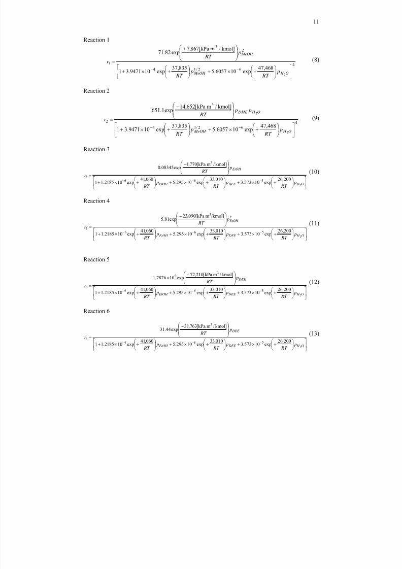
The forms of the rate equations for these reactions are taken from references 1 and 2, and are:
8/9/2019 Diethyl Ether Plant
http://slidepdf.com/reader/full/diethyl-ether-plant 11/21
11
Reaction 1
462/14
23
1
2
468,47exp106057.5
835,37exp109471.31
kmol]/mkPa[867,7exp82.71
⎥⎦
⎤⎢⎣
⎡⎟
⎠
⎞⎜
⎝
⎛ +×+⎟
⎠
⎞⎜
⎝
⎛ +×+
⎟⎟ ⎠
⎞⎜⎜⎝
⎛ +
=−−
O H MeOH
MeOH
p
RT
p
RT
p RT
r (8)
Reaction 2
462/14
3
2
2
2
468,47exp106057.5
835,37exp109471.31
kmol]/mkPa[652,14exp1.651
⎥⎦
⎤⎢⎣
⎡⎟ ⎠
⎞⎜⎝
⎛ +×+⎟ ⎠
⎞⎜⎝
⎛ +×+
⎟⎟ ⎠
⎞⎜⎜⎝
⎛ −
=−−
O H MeOH
O H DME
p RT
p RT
p p RT
r (9)
Reaction 3
⎥⎦
⎤⎢⎣
⎡⎟ ⎠
⎞⎜⎝
⎛ +×+⎟
⎠
⎞⎜⎝
⎛ +×+⎟
⎠
⎞⎜⎝
⎛ +×+
⎟⎟ ⎠
⎞⎜⎜⎝
⎛ −
=−−−
O H DEE EtOH
EtOH
p RT
p RT
p RT
p RT
r
2
200,26exp10573.3
010,33exp10295.5
060,41exp102185.11
kmol]/mkPa[770,1exp08345.0
566
3
3
(10)
Reaction 4
⎥⎦⎤⎢
⎣⎡ ⎟
⎠ ⎞⎜
⎝ ⎛ +×+⎟
⎠ ⎞⎜
⎝ ⎛ +×+⎟
⎠ ⎞⎜
⎝ ⎛ +×+
⎟⎟ ⎠
⎞⎜⎜⎝
⎛ −
=−−−
O H DEE EtOH
EtOH
p RT
p RT
p RT
p RT
r
2
200,26exp10573.3010,33exp10295.5060,41exp102185.11
/kmol]mkPa[090,23exp81.5
566
23
4
(11)
Reaction 5
⎥⎦
⎤⎢⎣
⎡⎟ ⎠
⎞⎜⎝
⎛ +×+⎟ ⎠
⎞⎜⎝
⎛ +×+⎟ ⎠
⎞⎜⎝
⎛ +×+
⎟⎟ ⎠
⎞⎜⎜⎝
⎛ −×
=−−−
O H DEE EtOH
DEE
p RT
p RT
p RT
p RT
r
2
200,26exp10573.3
010,33exp10295.5
060,41exp102185.11
kmol]/mkPa[210,72exp107876.1
566
35
5
(12)
Reaction 6
⎥⎦
⎤⎢⎣
⎡⎟ ⎠
⎞⎜⎝
⎛ +×+⎟ ⎠
⎞⎜⎝
⎛ +×+⎟ ⎠
⎞⎜⎝
⎛ +×+
⎟⎟ ⎠
⎞⎜⎜⎝
⎛ −
=−−−
O H DEE EtOH
DEE
p RT
p RT
p RT
p RT
r
2
200,26exp10573.3
010,33exp10295.5
060,41exp102185.11
kmol]/mkPa[763,31exp44.31
566
3
6
(13)
8/9/2019 Diethyl Ether Plant
http://slidepdf.com/reader/full/diethyl-ether-plant 12/21
12
The units of the reaction rate are kmol/m3
reactor /h. The catalyst is diluted by a factor of 10; hence,
the volumes given in the Chemcad simulation should be multiplied by 10 to get the volume ofthe catalyst bed. It should be noted that the term in the exponential in the numerator of Reaction
1 (that looks like an activation energy) is negative. This is unusual; however, the term in the
numerator is actually the product of a rate constant (with a positive activation energy) and two
adsorption constants (with negative adsorption energies). The net result is a negative value forthe term in the exponential. This reaction rate form will give a warning in Chemcad, but you can
ignore this during the simulation. It should also be noted that the terms in the denominators are
adsorption rates with negative adsorption or activation energies. The net result for all reactionsis that, as the temperature increases, the overall reaction rates given by the above equations all
increase. This is consistent with our intuition.
1. Butt, J. B., H. Bliss, and C. A. Walker, “Rates of Reaction in a Recycling System –
Dehydration of Ethanol and Diethyl Ether Over Alumina,” AIChE-J , 8, 42-47 (1962).
2. Ber čič, G. and J. Lavec, “Intrinsic and Global Reaction Rates of Methanol Dehydration over
γ-Al2O3 Pellets,” Ind. Eng. Chem. Res., 31, 1035-1040 (1992).
8/9/2019 Diethyl Ether Plant
http://slidepdf.com/reader/full/diethyl-ether-plant 13/21
13
Appendix 2
Calculations and Other Pertinent Information
Azeotropic behavior of DEE-water mixtures
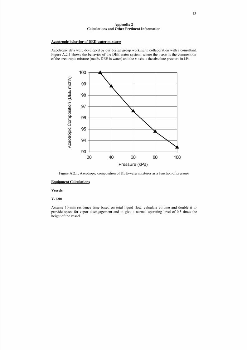
Azeotropic data were developed by our design group working in collaboration with a consultant.
Figure A.2.1 shows the behavior of the DEE-water system, where the y-axis is the composition
of the azeotropic mixture (mol% DEE in water) and the x-axis is the absolute pressure in kPa.
Figure A.2.1: Azeotropic composition of DEE-water mixtures as a function of pressure
Equipment Calculations
Vessels
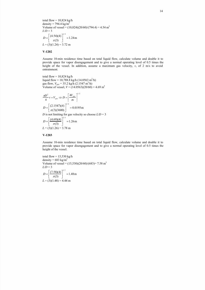
V-1201
Assume 10-min residence time based on total liquid flow, calculate volume and double it to
provide space for vapor disengagement and to give a normal operating level of 0.5 times theheight of the vessel.
8/9/2019 Diethyl Ether Plant
http://slidepdf.com/reader/full/diethyl-ether-plant 14/21
14
total flow = 10,824 kg/h
density = 794.4 kg/m3
Volume of vessel = (10,824)(20/60)/(794.4) = 4.54 m3
L/ D = 3
m24.1)3(
)4)(54.4(3/1
=⎥⎦
⎤
⎢⎣
⎡
= π D
L = (3)(1.24) = 3.72 m
V-1202
Assume 10-min residence time based on total liquid flow, calculate volume and double it to provide space for vapor disengagement and to give a normal operating level of 0.5 times the
height of the vessel. In addition, assume a maximum gas velocity, v, of 2 m/s to avoid
entrainment.
total flow = 10,824 kg/h
liquid flow = 10,788.8 kg/h (14.0563 m3/h)gas flow, V gas = 35.2 kg/h (2.1547 m
3/h)
Volume of vessel, V = (14.0563)(20/60) = 4.69 m3
2/12 4
4 ⎥
⎦
⎤⎢⎣
⎡=⇒=
v
V DV v
D gas
gasπ
π
m0195.0)3600)(2(
)4)(1547.2(2/1
=⎥⎦
⎤⎢⎣
⎡=
π D
D is not limiting for gas velocity so choose L/ D = 3
m26.1)3(
)4)(69.4( 3/1
=⎥⎦
⎤⎢⎣
⎡=π
D
L = (3)(1.26) = 3.78 m
V-1203
Assume 10-min residence time based on total liquid flow, calculate volume and double it to provide space for vapor disengagement and to give a normal operating level of 0.5 times the
height of the vessel.
total flow = 15,530 kg/h
density = 683 kg/m3
Volume of vessel = (15,530)(20/60)/(683)= 7.58 m3
L/ D = 3
m48.1)3(
)4)(58.7(3/1
=⎥⎦
⎤⎢⎣
⎡=
π D
L = (3)(1.48) = 4.44 m
8/9/2019 Diethyl Ether Plant
http://slidepdf.com/reader/full/diethyl-ether-plant 15/21
15
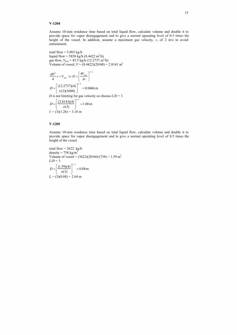
V-1204
Assume 10-min residence time based on total liquid flow, calculate volume and double it to
provide space for vapor disengagement and to give a normal operating level of 0.5 times the
height of the vessel. In addition, assume a maximum gas velocity, v, of 2 m/s to avoid
entrainment.
total flow = 5,903 kg/h
liquid flow = 5858 kg/h (8.4422 m3/h)
gas flow, V gas = 45.5 kg/h (12.2737 m3/h)
Volume of vessel, V = (8.4422)(20/60) = 2.8141 m3
2/12 4
4 ⎥
⎦
⎤⎢⎣
⎡=⇒=
v
V DV v
D gas
gasπ
π
m0466.0)3600)(2(
)4)(2737.12(2/1
=⎥⎦
⎤
⎢⎣
⎡=
π D
D is not limiting for gas velocity so choose L/ D = 3
m06.1)3(
)4)(8141.2(3/1
=⎥⎦
⎤⎢⎣
⎡=
π D
L = (3)(1.26) = 3.18 m
V-1205
Assume 10-min residence time based on total liquid flow, calculate volume and double it to
provide space for vapor disengagement and to give a normal operating level of 0.5 times theheight of the vessel.
total flow = 3622 kg/h
density = 758 kg/m3
Volume of vessel = (3622)(20/60)/(758) = 1.59 m3
L/ D = 3
m88.0)3(
)4)(59.1(3/1
=⎥⎦
⎤⎢⎣
⎡=
π D
L = (3)(0.88) = 2.64 m
8/9/2019 Diethyl Ether Plant
http://slidepdf.com/reader/full/diethyl-ether-plant 16/21
16
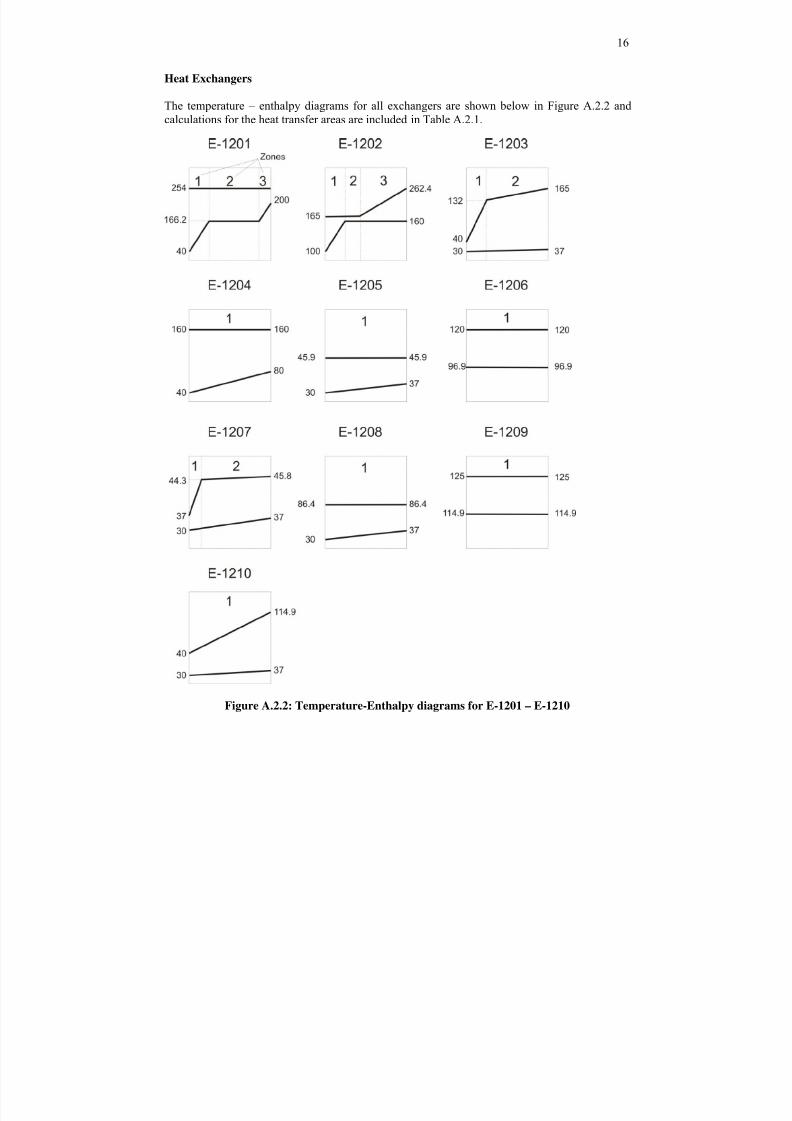
Heat Exchangers
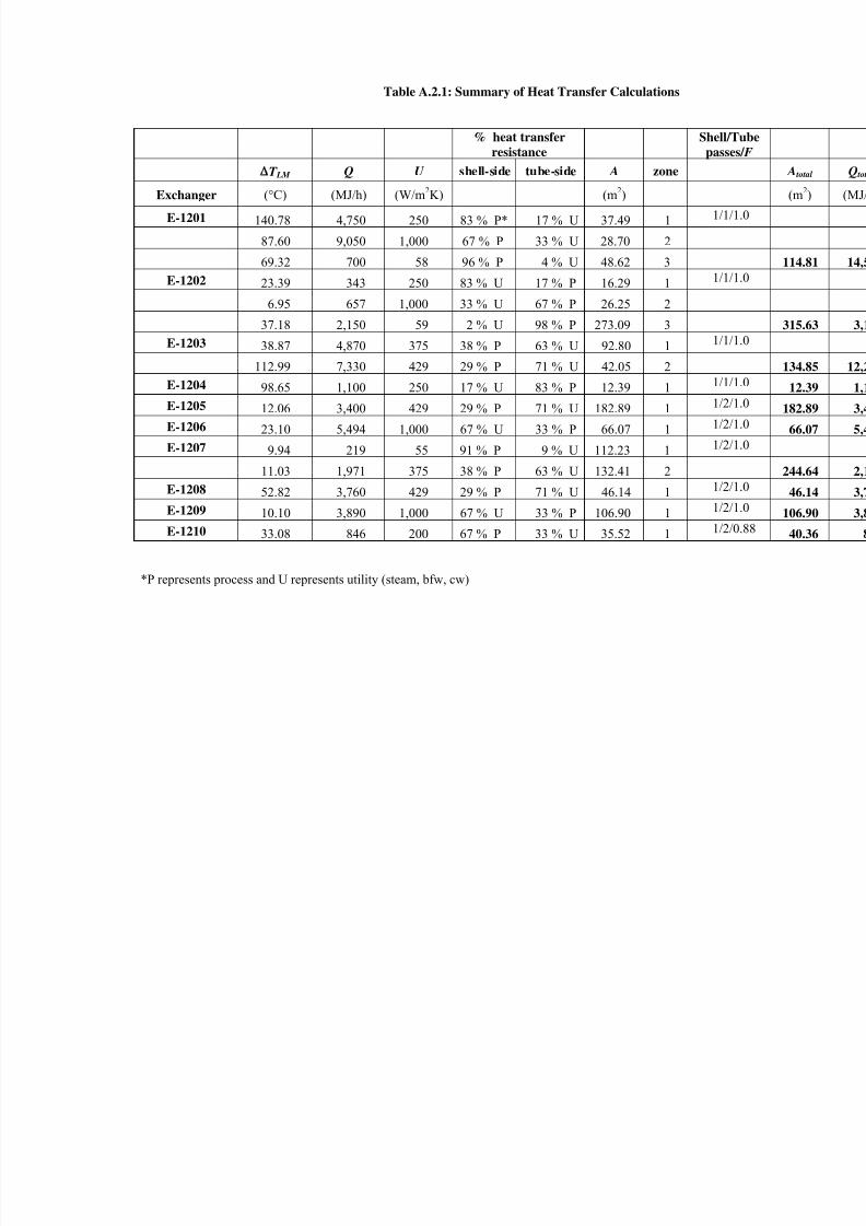
The temperature – enthalpy diagrams for all exchangers are shown below in Figure A.2.2 and
calculations for the heat transfer areas are included in Table A.2.1.
Figure A.2.2: Temperature-Enthalpy diagrams for E-1201 – E-1210
8/9/2019 Diethyl Ether Plant
http://slidepdf.com/reader/full/diethyl-ether-plant 17/21
Table A.2.1: Summary of Heat Transfer Calculations
% heat transfer
resistance
Shell
pas
T LM Q U shell-side tube-side A zone
Exchanger (°C) (MJ/h) (W/m2K) (m
2)
E-1201 140.78 4,750 250 83 % P* 17 % U 37.49 1 1/
87.60 9,050 1,000 67 % P 33 % U 28.70 2
69.32 700 58 96 % P 4 % U 48.62 3
E-1202 23.39 343 250 83 % U 17 % P 16.29 1 1/
6.95 657 1,000 33 % U 67 % P 26.25 2
37.18 2,150 59 2 % U 98 % P 273.09 3E-1203 38.87 4,870 375 38 % P 63 % U 92.80 1 1/
112.99 7,330 429 29 % P 71 % U 42.05 2
E-1204 98.65 1,100 250 17 % U 83 % P 12.39 1 1/
E-1205 12.06 3,400 429 29 % P 71 % U 182.89 1 1/2
E-1206 23.10 5,494 1,000 67 % U 33 % P 66.07 1 1/2
E-1207 9.94 219 55 91 % P 9 % U 112.23 1 1/2
11.03 1,971 375 38 % P 63 % U 132.41 2
E-1208 52.82 3,760 429 29 % P 71 % U 46.14 11/2
E-1209 10.10 3,890 1,000 67 % U 33 % P 106.90 1 1/2
E-1210 33.08 846 200 67 % P 33 % U 35.52 1 1/2
*P represents process and U represents utility (steam, bfw, cw)
8/9/2019 Diethyl Ether Plant
http://slidepdf.com/reader/full/diethyl-ether-plant 18/21
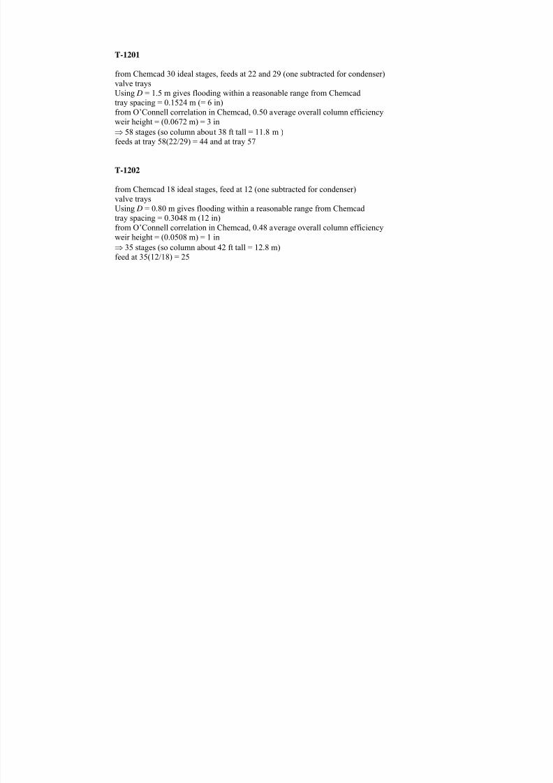
T-1201
from Chemcad 30 ideal stages, feeds at 22 and 29 (one subtracted for condenser)
valve trays
Using D = 1.5 m gives flooding within a reasonable range from Chemcad
tray spacing = 0.1524 m (= 6 in)from O’Connell correlation in Chemcad, 0.50 average overall column efficiency
weir height = (0.0672 m) = 3 in
⇒ 58 stages (so column about 38 ft tall = 11.8 m )feeds at tray 58(22/29) = 44 and at tray 57
T-1202
from Chemcad 18 ideal stages, feed at 12 (one subtracted for condenser)
valve trays
Using D = 0.80 m gives flooding within a reasonable range from Chemcadtray spacing = 0.3048 m (12 in)
from O’Connell correlation in Chemcad, 0.48 average overall column efficiency
weir height = (0.0508 m) = 1 in
⇒ 35 stages (so column about 42 ft tall = 12.8 m)feed at 35(12/18) = 25
8/9/2019 Diethyl Ether Plant
http://slidepdf.com/reader/full/diethyl-ether-plant 19/21
19
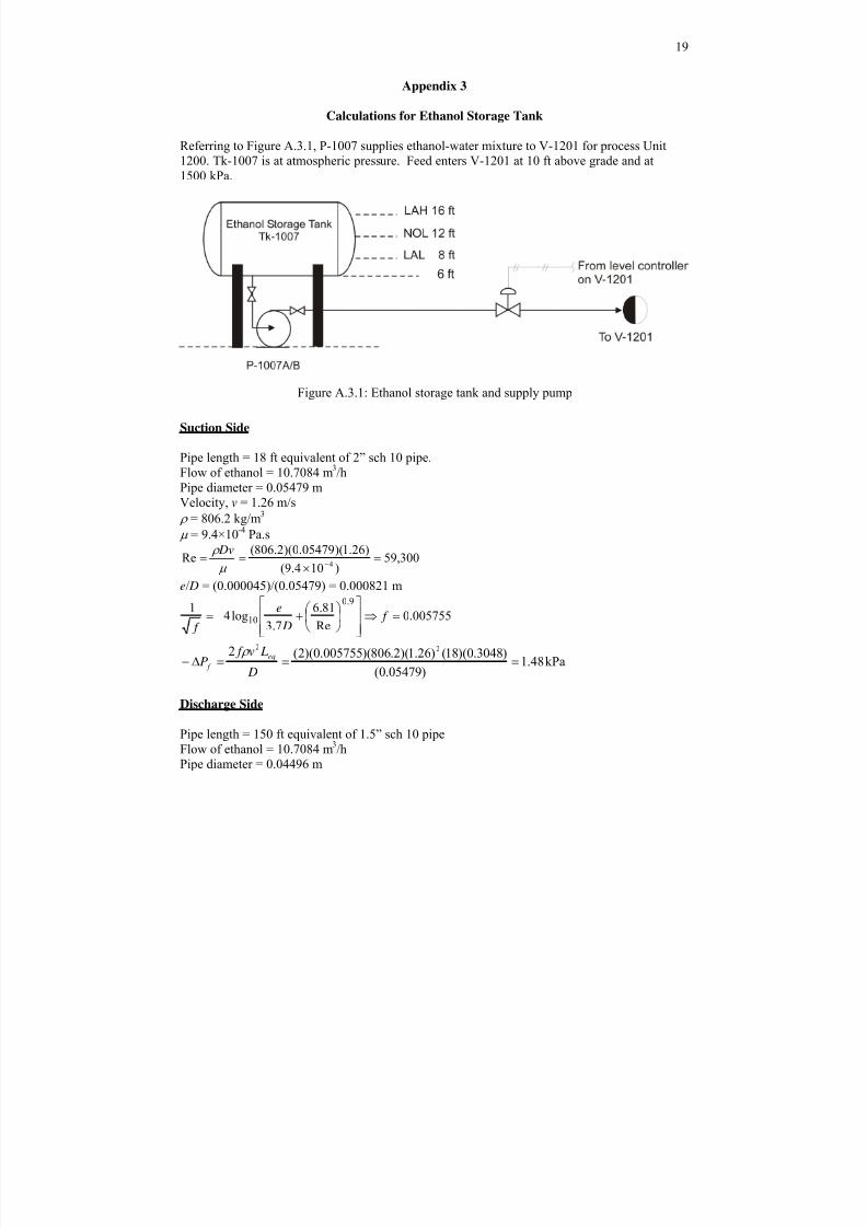
Appendix 3
Calculations for Ethanol Storage Tank
Referring to Figure A.3.1, P-1007 supplies ethanol-water mixture to V-1201 for process Unit
1200. Tk-1007 is at atmospheric pressure. Feed enters V-1201 at 10 ft above grade and at1500 kPa.
Figure A.3.1: Ethanol storage tank and supply pump
Suction Side
Pipe length = 18 ft equivalent of 2” sch 10 pipe. Flow of ethanol = 10.7084 m
3/h
Pipe diameter = 0.05479 m
Velocity, v = 1.26 m/s
ρ = 806.2 kg/m3
μ = 9.4×10⁻⁴
Pa.s
300,59)104.9(
)26.1)(05479.0)(2.806(Re
4 =
×==
−μ
ρ Dv
e/ D = (0.000045)/(0.05479) = 0.000821 m
005755.0Re
81.6
7.3log4
19.0
10 =⇒⎥⎥⎦
⎤
⎢⎢⎣
⎡⎟ ⎠
⎞⎜⎝
⎛ +−= f D
e
f
kPa48.1)05479.0(
)3048.0)(18()26.1)(2.806)(005755.0)(2(2 22
===Δ− D
Lv f
P eq
f
ρ
Discharge Side
Pipe length = 150 ft equivalent of 1.5” sch 10 pipe
Flow of ethanol = 10.7084 m3/h
Pipe diameter = 0.04496 m
8/9/2019 Diethyl Ether Plant
http://slidepdf.com/reader/full/diethyl-ether-plant 20/21
20
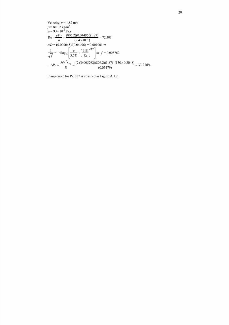
Velocity, v = 1.87 m/s
ρ = 806.2 kg/m3
μ = 9.4×10⁻⁴
Pa.s
300,72)104.9(
)87.1)(0.04496)(2.806(Re
4 =
×==
−μ
ρ Dv
e/ D = (0.000045)/(0.04496) = 0.001001 m
005762.0Re
81.6
7.3log4
19.0
10 =⇒⎥⎥⎦
⎤
⎢⎢⎣
⎡⎟ ⎠
⎞⎜⎝
⎛ +−= f D
e
f
kPa2.33)05479.0(
)3048.0150()87.1)(2.806)(005762.0)(2( 22
=×
==Δ− D
Lv f P
eq
f
ρ
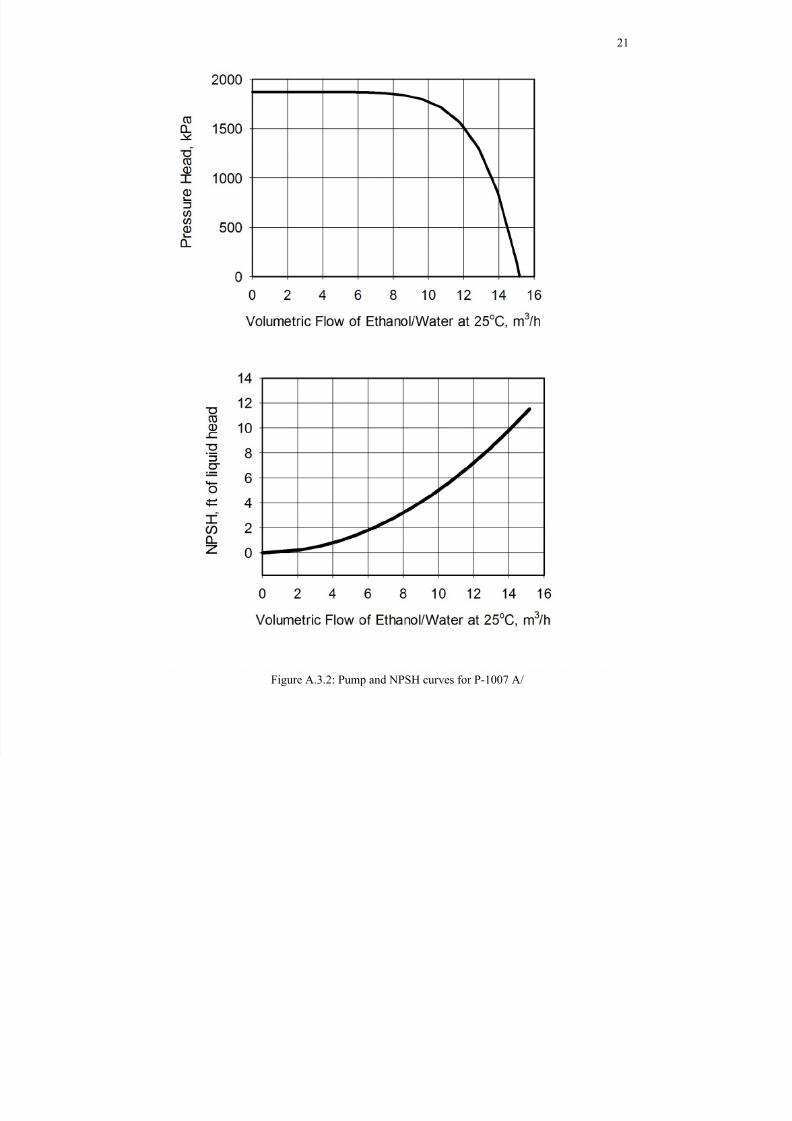
Pump curve for P-1007 is attached as Figure A.3.2.
8/9/2019 Diethyl Ether Plant
http://slidepdf.com/reader/full/diethyl-ether-plant 21/21
21
Figure A.3.2: Pump and NPSH curves for P-1007 A/