Embed Size (px)
Citation preview
DIE SETUP PROCEDURE
“A” DIE
“A” Die - 1 15-Jan-99
“A” DIE SETUP PROCEDURE
Major Components of Die
1. CRIMP ANVILS
2. SHANK
3. BRAKE PIN
4. CRIMP STATION 5. FEED FINGER 6. FEED FINGER SET
SCREW 7. STOCK GUIDE 8. CRIMP PLATES 9. STOCK SUPPORT PLATE 10. TERMINAL PROGRESSION
SCREW 11. HOOK RAIL
Figure 1-2
1
Figure 1-1
Figure 1-3
3
7
2
9
8
11
“A” Die - 2 15-Jan-99
“A” DIE SETUP PROCEDURE
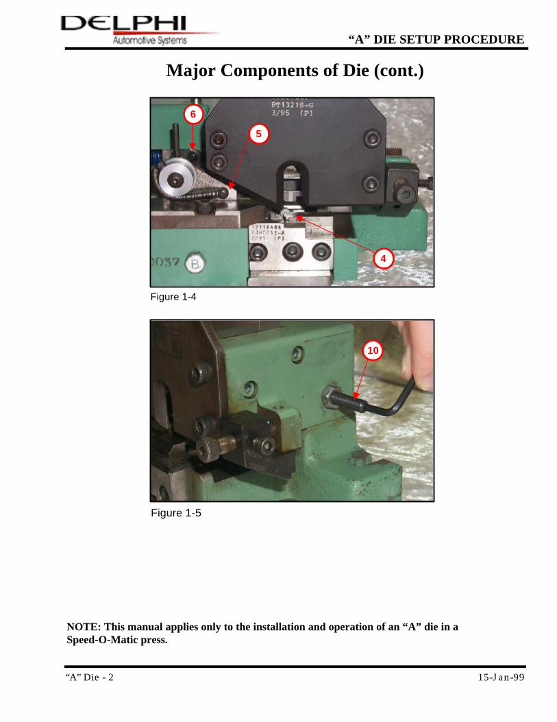
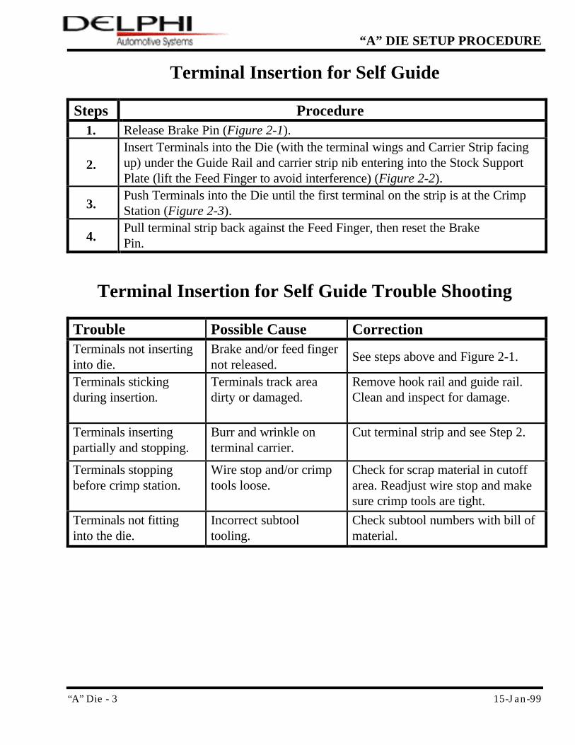
Major Components of Die (cont.)
4
Figure 1-4
5
6
10
Figure 1-5
NOTE: This manual applies only to the installation and operation of an “A” die in a Speed-O-Matic press.
“A” Die - 3 15-Jan-99
“A” DIE SETUP PROCEDURE
Terminal Insertion for Self Guide
Steps Procedure 1. Release Brake Pin (Figure 2-1).
2. Insert Terminals into the Die (with the terminal wings and Carrier Strip facing up) under the Guide Rail and carrier strip nib entering into the Stock Support Plate (lift the Feed Finger to avoid interference) (Figure 2-2).
3. Push Terminals into the Die until the first terminal on the strip is at the Crimp Station (Figure 2-3).
4. Pull terminal strip back against the Feed Finger, then reset the Brake Pin.
Terminal Insertion for Self Guide Trouble Shooting
Trouble Possible Cause Correction Terminals not inserting into die.
Brake and/or feed finger not released.
See steps above and Figure 2-1.
Terminals sticking during insertion.
Terminals track area dirty or damaged.
Remove hook rail and guide rail. Clean and inspect for damage.
Terminals inserting partially and stopping.
Burr and wrinkle on terminal carrier.
Cut terminal strip and see Step 2.
Terminals stopping before crimp station.
Wire stop and/or crimp tools loose.
Check for scrap material in cutoff area. Readjust wire stop and make sure crimp tools are tight.
Terminals not fitting into the die.
Incorrect subtool tooling.
Check subtool numbers with bill of material.
“A” Die - 4 15-Jan-99
“A” DIE SETUP PROCEDURE
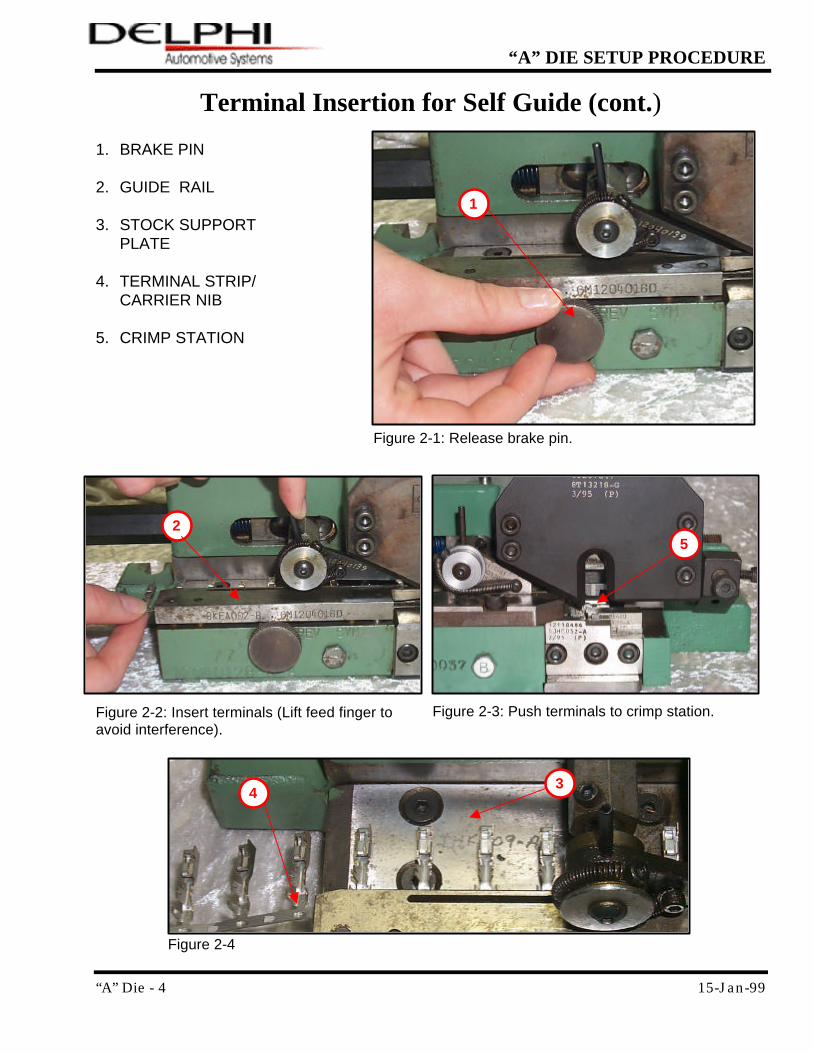
Terminal Insertion for Self Guide (cont.)
1. BRAKE PIN 2. GUIDE RAIL 3. STOCK SUPPORT PLATE 4. TERMINAL STRIP/
CARRIER NIB 5. CRIMP STATION
Figure 2-1: Release brake pin.
Figure 2-2: Insert terminals (Lift feed finger to avoid interference).
1
Figure 2-3: Push terminals to crimp station.
3
2
Figure 2-4
5
4
“A” Die - 5 15-Jan-99
“A” DIE SETUP PROCEDURE
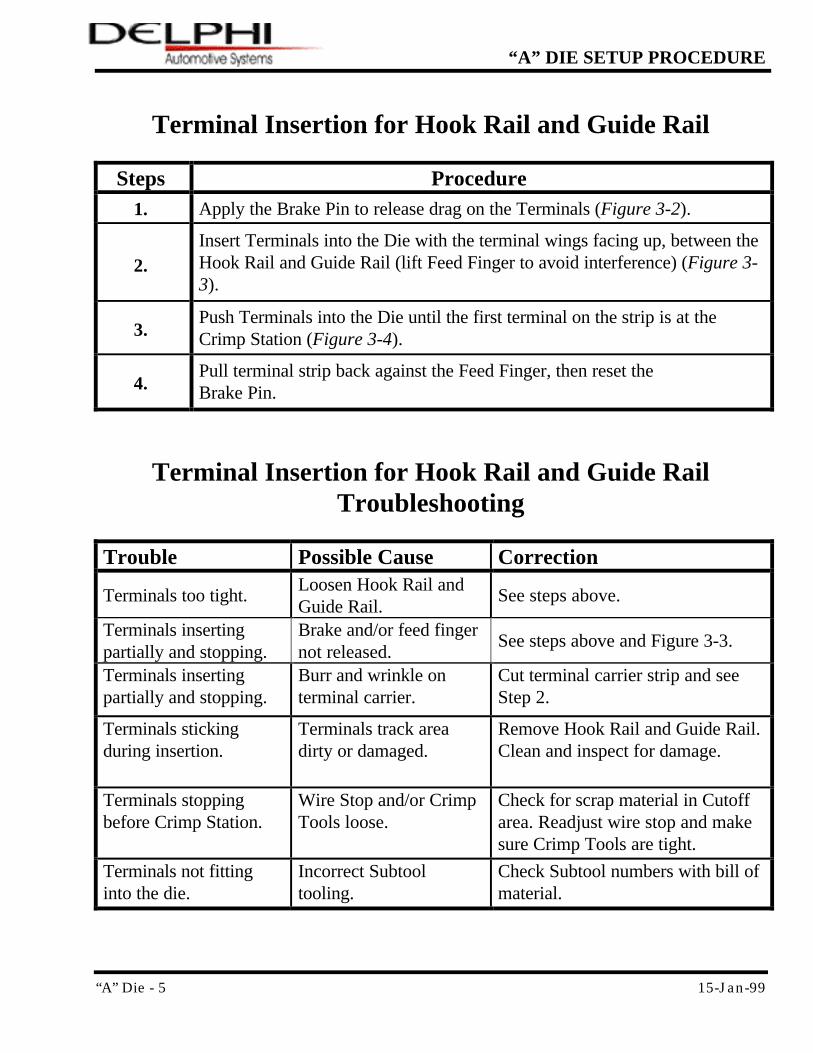
Terminal Insertion for Hook Rail and Guide Rail
Steps Procedure 1. Apply the Brake Pin to release drag on the Terminals (Figure 3-2).
2. Insert Terminals into the Die with the terminal wings facing up, between the Hook Rail and Guide Rail (lift Feed Finger to avoid interference) (Figure 3-3).
3. Push Terminals into the Die until the first terminal on the strip is at the Crimp Station (Figure 3-4).
4. Pull terminal strip back against the Feed Finger, then reset the Brake Pin.
Terminal Insertion for Hook Rail and Guide Rail Troubleshooting
Trouble Possible Cause Correction
Terminals too tight. Loosen Hook Rail and Guide Rail.
See steps above.
Terminals inserting partially and stopping.
Brake and/or feed finger not released.
See steps above and Figure 3-3.
Terminals inserting partially and stopping.
Burr and wrinkle on terminal carrier.
Cut terminal carrier strip and see Step 2.
Terminals sticking during insertion.
Terminals track area dirty or damaged.
Remove Hook Rail and Guide Rail. Clean and inspect for damage.
Terminals stopping before Crimp Station.
Wire Stop and/or Crimp Tools loose.
Check for scrap material in Cutoff area. Readjust wire stop and make sure Crimp Tools are tight.
Terminals not fitting into the die.
Incorrect Subtool tooling.
Check Subtool numbers with bill of material.
“A” Die - 6 15-Jan-99
“A” DIE SETUP PROCEDURE
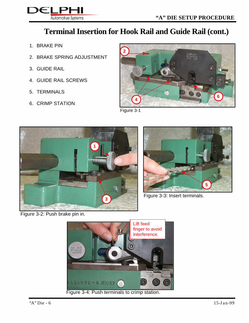
Terminal Insertion for Hook Rail and Guide Rail (cont.)
1. BRAKE PIN 2. BRAKE SPRING ADJUSTMENT 3. GUIDE RAIL 4. GUIDE RAIL SCREWS 5. TERMINALS 6. CRIMP STATION
Figure 3-3: Insert terminals.
Figure 3-2: Push brake pin in.
1
3
Figure 3-4: Push terminals to crimp station.
Lift feed finger to avoid interference.
Figure 3-1
2
6
5
4
“A” Die - 7 15-Jan-99
“A” DIE SETUP PROCEDURE
Self Guide Setup
Steps Procedure 1. There are no adjustments necessary for Self Guide setup.
NOTES:
Check to ensure terminals move freely (lift Feed Finger to avoid interference).
There is not an adjustment for Flare.
Self Guide Setup Trouble Shooting
Trouble Possible Cause Correction Terminals are not moving freely.
Debris in Guide system. Clean debris from Guide system.
Terminal will not line up with Crimp Anvils.
Incorrect Subtool tooling or camber in terminal strip.
Check Subtool numbers with bill of material. Make sure terminal strip is to spec.
“A” Die - 8 15-Jan-99
“A” DIE SETUP PROCEDURE
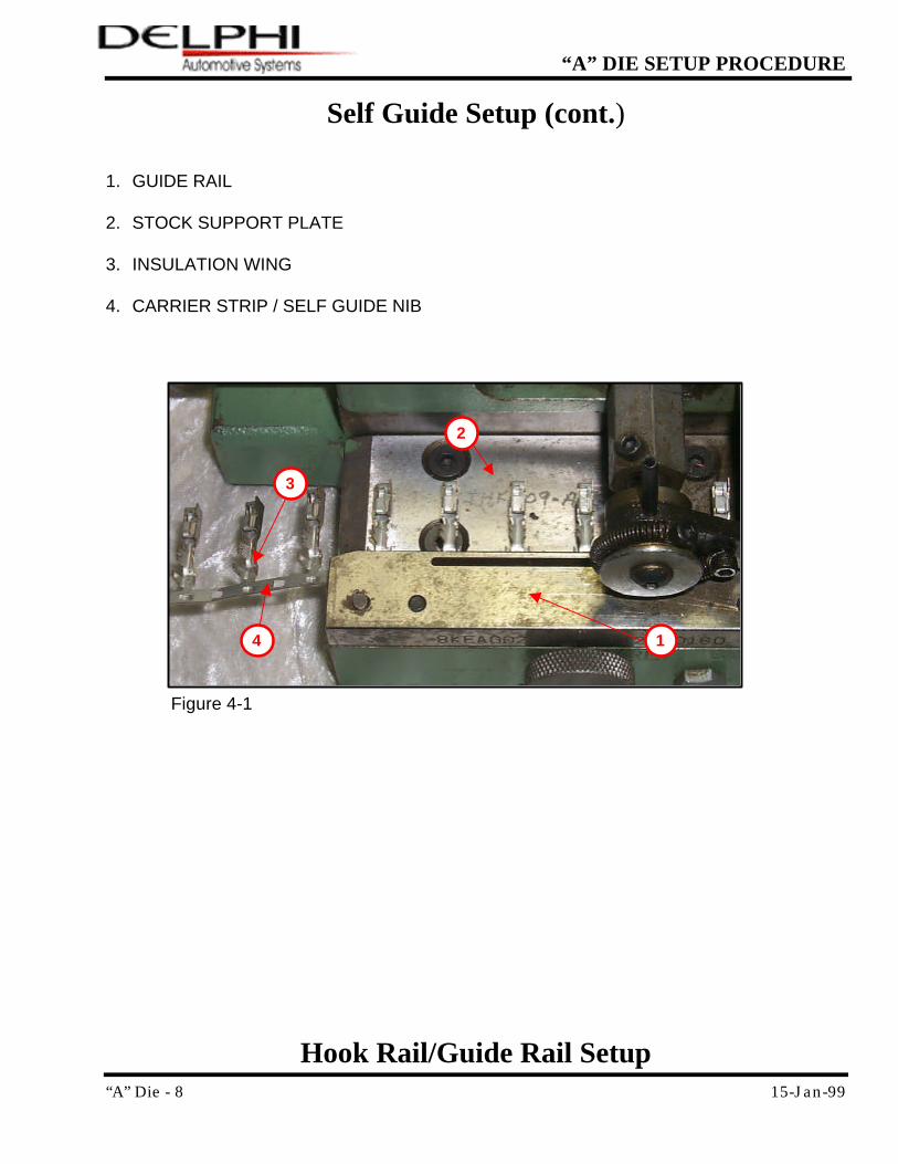
Self Guide Setup (cont.)
1. GUIDE RAIL 2. STOCK SUPPORT PLATE 3. INSULATION WING 4. CARRIER STRIP / SELF GUIDE NIB
Hook Rail/Guide Rail Setup
3
2
1 4
Figure 4-1
“A” Die - 9 15-Jan-99
“A” DIE SETUP PROCEDURE
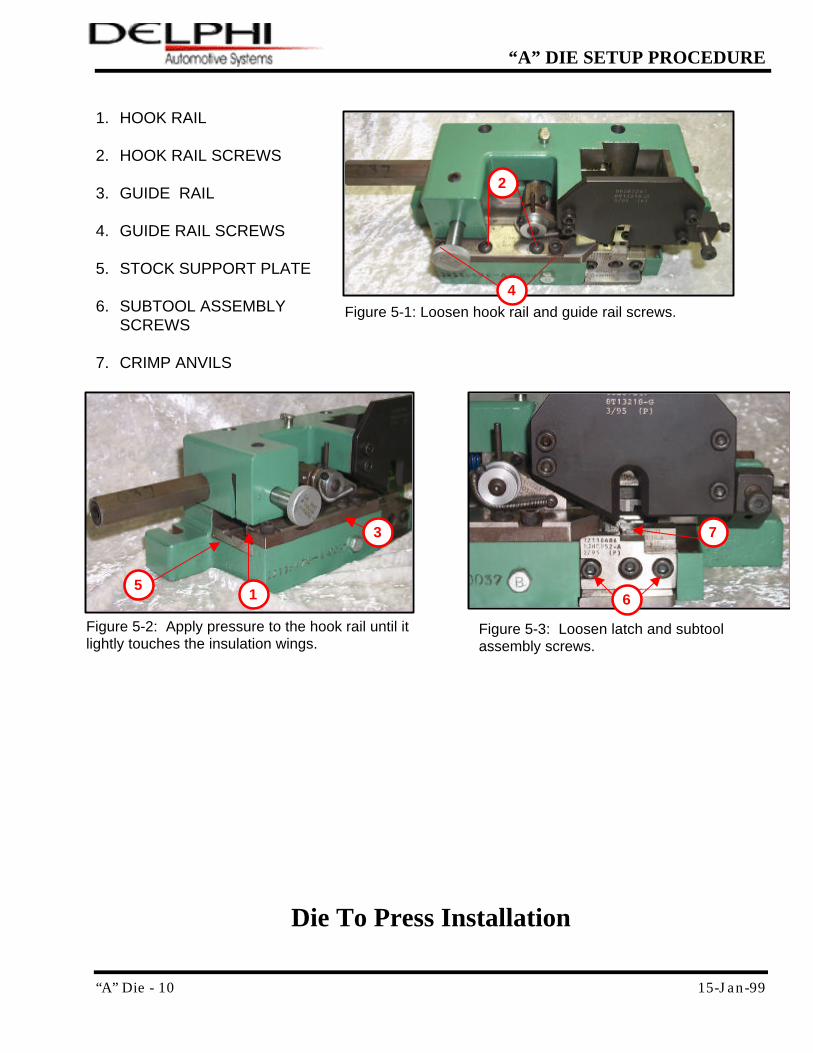
Steps Procedure 1. Loosen Hook Rail and Guide Rail screws (Figure 5-1).
2. Apply pressure to the Hook Rail until it touches the insulation wings (Figure 5-2).
3. Tighten the Guide Rail and Hook Rail screws. Recheck Terminal movement.
4. Loosen Latch and Subtool Assembly screws on the bottom of the assembly (ensure that the Hook Rail is resting on the insulation wings and not the core wings) (Figure 5-3).
5. Position the hole/neck of the Terminal (depending on terminal specifications) with the Feed Finger insert slot in the Support Plate.
6. When the terminal is centered front-to-back on the crimp anvils, tighten the mounting screws.
NOTE:
Check to ensure that the terminals move freely (lift Feed Finger).
Further adjustment may be required to adjust the Flare after a few crimp setups have been made.
Hook Rail/Guide Rail Setup
Troubleshooting
Trouble Possible Cause Correction Terminals are not moving freely.
Hook Rail and Guide Rail adjustment is too tight.
See Step 1 and Figure 5-2. Apply minimal pressure.
Terminals will not line up with Crimp Anvils.
Incorrect Subtool tooling or camber in terminal strip.
Realign Hook Rail and Guide Rail.
Hook Rail/Guide Rail Setup (cont.)
“A” Die - 10 15-Jan-99
“A” DIE SETUP PROCEDURE
1. HOOK RAIL 2. HOOK RAIL SCREWS 3. GUIDE RAIL 4. GUIDE RAIL SCREWS 5. STOCK SUPPORT PLATE 6. SUBTOOL ASSEMBLY
SCREWS 7. CRIMP ANVILS
Die To Press Installation
Figure 5-1: Loosen hook rail and guide rail screws.
Figure 5-2: Apply pressure to the hook rail until it lightly touches the insulation wings.
3
1
7
Figure 5-3: Loosen latch and subtool assembly screws.
5 6
4
2
“A” Die - 11 15-Jan-99
“A” DIE SETUP PROCEDURE
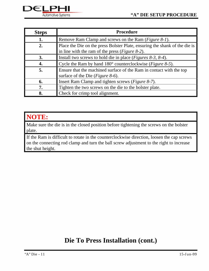
Steps Procedure
1. Remove Ram Clamp and screws on the Ram (Figure 8-1). 2. Place the Die on the press Bolster Plate, ensuring the shank of the die is
in line with the ram of the press (Figure 8-2). 3. Install two screws to hold die in place (Figures 8-3, 8-4). 4. Cycle the Ram by hand 180° counterclockwise (Figure 8-5). 5. Ensure that the machined surface of the Ram in contact with the top
surface of the Die (Figure 8-6). 6. Insert Ram Clamp and tighten screws (Figure 8-7). 7. Tighten the two screws on the die to the bolster plate. 8. Check for crimp tool alignment.
NOTE:
Make sure the die is in the closed position before tightening the screws on the bolster plate.
If the Ram is difficult to rotate in the counterclockwise direction, loosen the cap screws on the connecting rod clamp and turn the ball screw adjustment to the right to increase the shut height.
Die To Press Installation (cont.)
“A” Die - 12 15-Jan-99
“A” DIE SETUP PROCEDURE
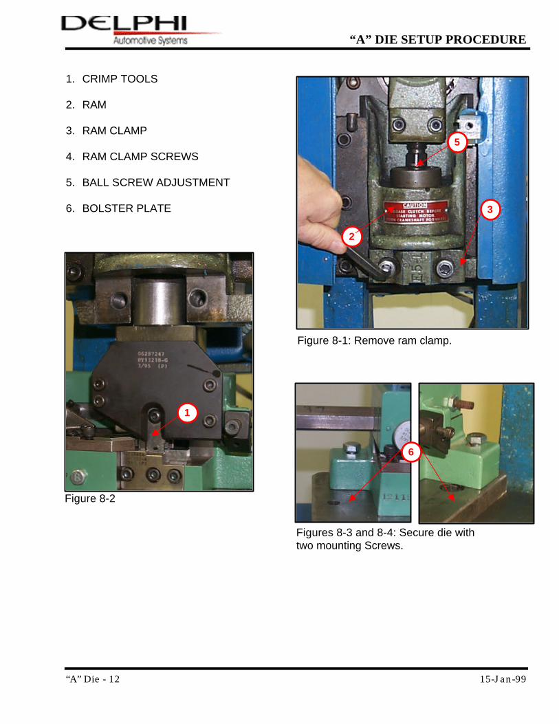
1. CRIMP TOOLS
2. RAM
3. RAM CLAMP 4. RAM CLAMP SCREWS
5. BALL SCREW ADJUSTMENT
6. BOLSTER PLATE
Figure 8-1: Remove ram clamp.
Figure 8-2
Figures 8-3 and 8-4: Secure die with two mounting Screws.
1
3
2
5
6
“A” Die - 13 15-Jan-99
“A” DIE SETUP PROCEDURE
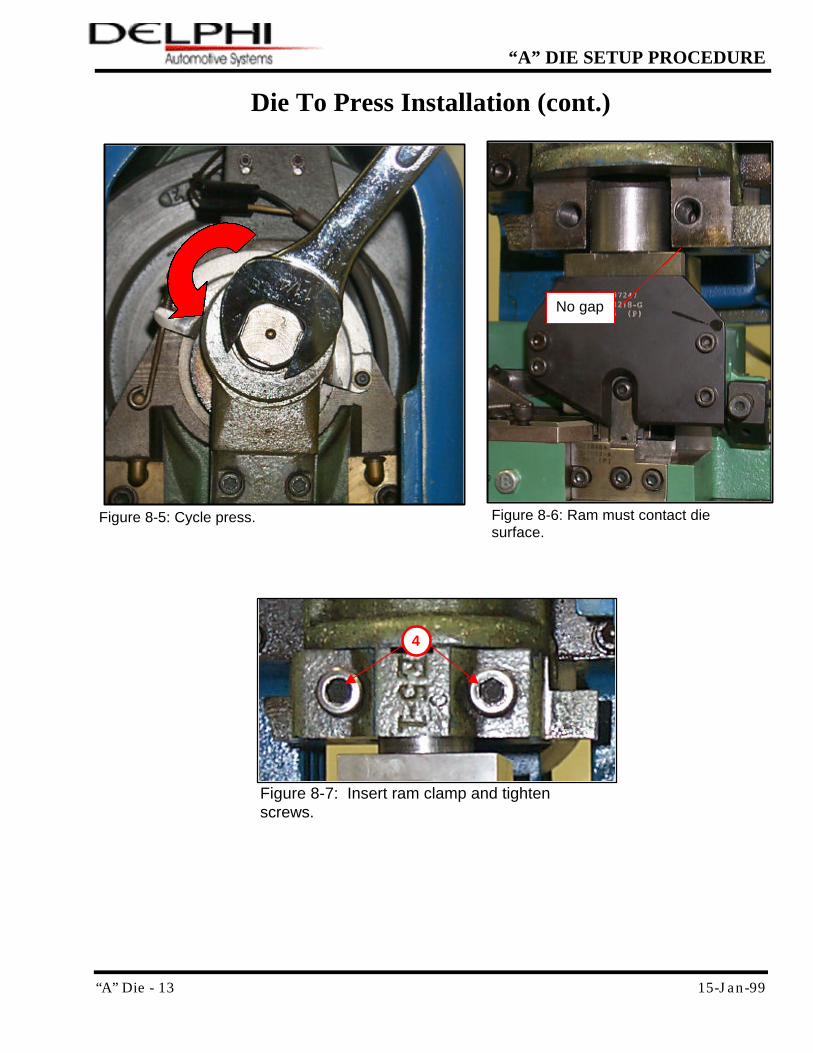
Die To Press Installation (cont.)
Figure 8-5: Cycle press. Figure 8-6: Ram must contact die surface.
No gap
Figure 8-7: Insert ram clamp and tighten screws.
4
“A” Die - 14 15-Jan-99
“A” DIE SETUP PROCEDURE
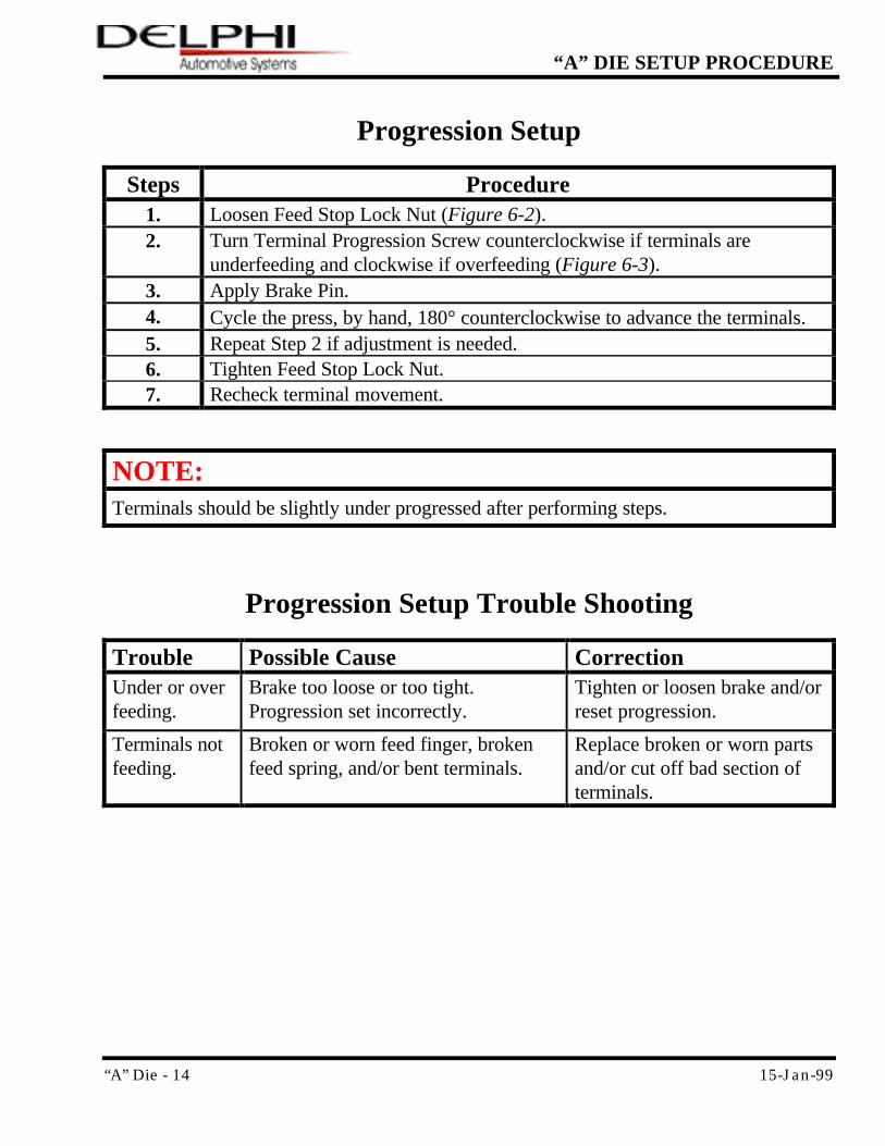
Progression Setup
Steps Procedure 1. Loosen Feed Stop Lock Nut (Figure 6-2). 2. Turn Terminal Progression Screw counterclockwise if terminals are
underfeeding and clockwise if overfeeding (Figure 6-3). 3. Apply Brake Pin. 4. Cycle the press, by hand, 180° counterclockwise to advance the terminals. 5. Repeat Step 2 if adjustment is needed. 6. Tighten Feed Stop Lock Nut. 7. Recheck terminal movement.
NOTE:
Terminals should be slightly under progressed after performing steps.
Progression Setup Trouble Shooting
Trouble Possible Cause Correction Under or over feeding.
Brake too loose or too tight. Progression set incorrectly.
Tighten or loosen brake and/or reset progression.
Terminals not feeding.
Broken or worn feed finger, broken feed spring, and/or bent terminals.
Replace broken or worn parts and/or cut off bad section of terminals.
“A” Die - 15 15-Jan-99
“A” DIE SETUP PROCEDURE
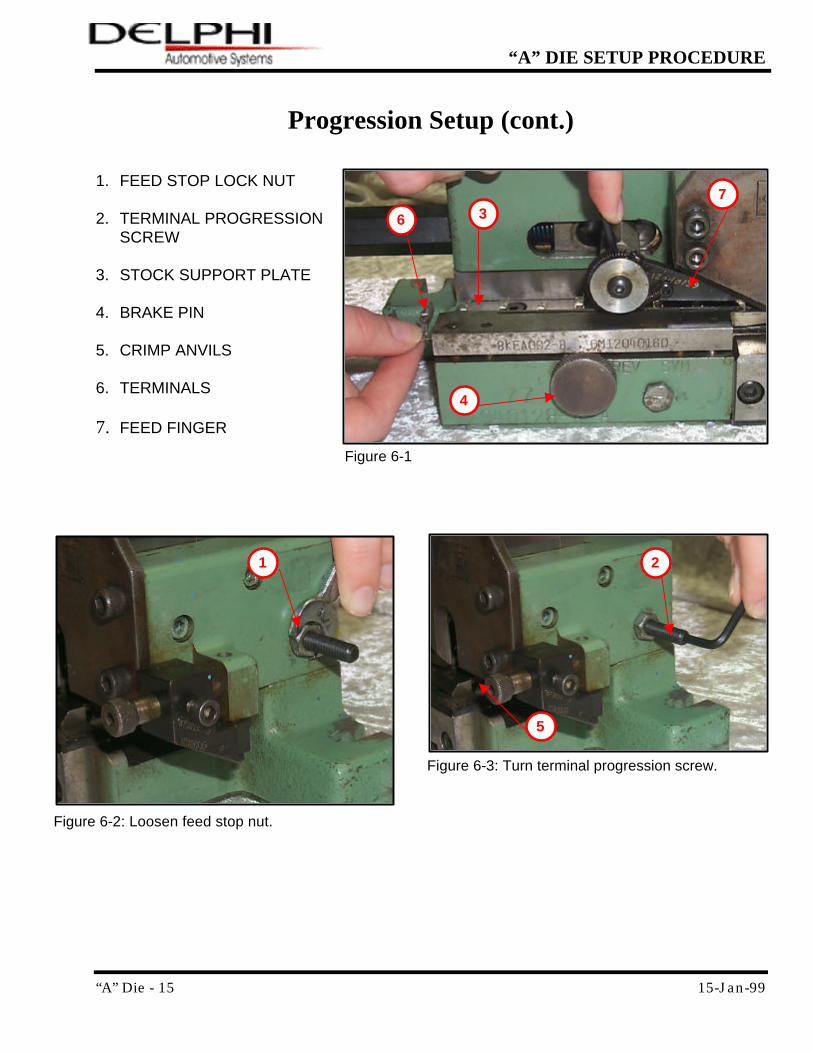
Progression Setup (cont.) 1. FEED STOP LOCK NUT
2. TERMINAL PROGRESSION
SCREW
3. STOCK SUPPORT PLATE
4. BRAKE PIN 5. CRIMP ANVILS
6. TERMINALS
7. FEED FINGER
Figure 6-2: Loosen feed stop nut.
Figure 6-3: Turn terminal progression screw.
Figure 6-1
3
4
5
1 2
6
7
“A” Die - 16 15-Jan-99
“A” DIE SETUP PROCEDURE
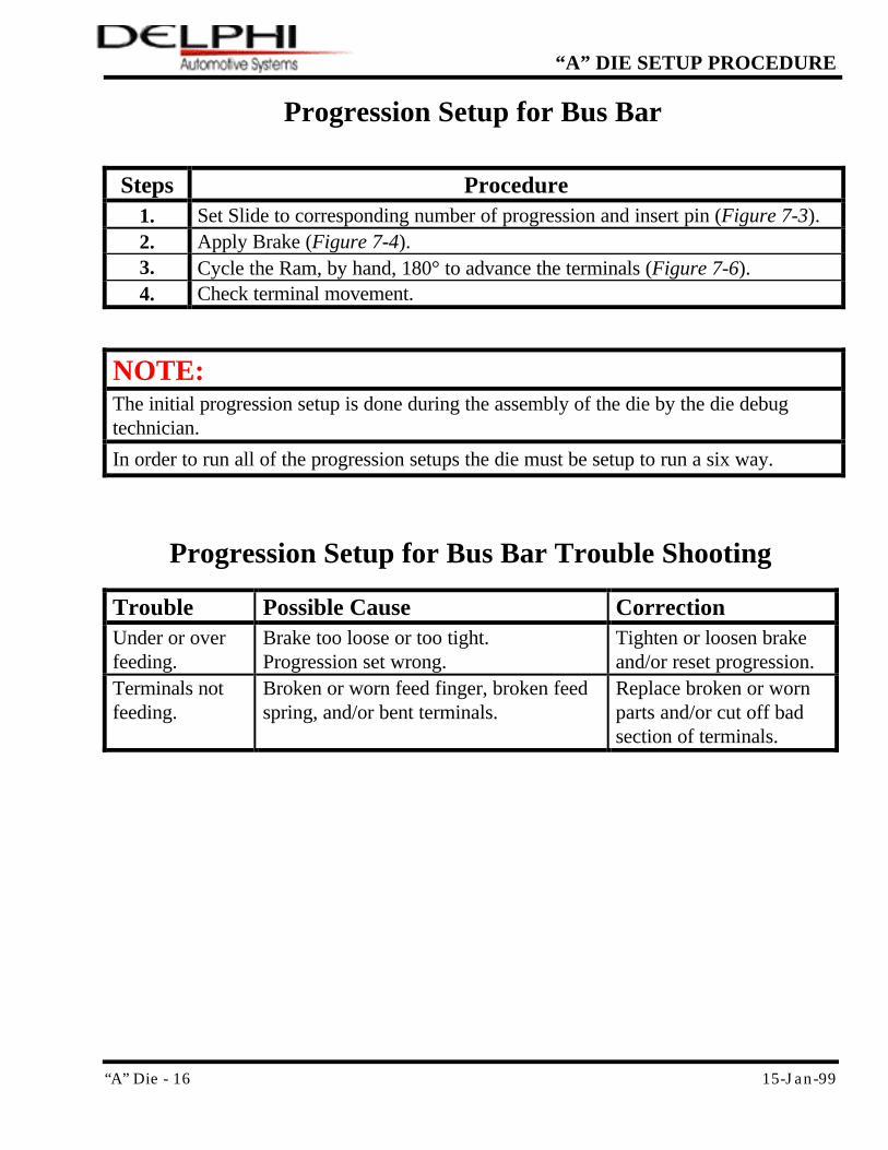
Progression Setup for Bus Bar
Steps Procedure 1. Set Slide to corresponding number of progression and insert pin (Figure 7-3). 2. Apply Brake (Figure 7-4). 3. Cycle the Ram, by hand, 180° to advance the terminals (Figure 7-6). 4. Check terminal movement.
NOTE:
The initial progression setup is done during the assembly of the die by the die debug technician.
In order to run all of the progression setups the die must be setup to run a six way.
Progression Setup for Bus Bar Trouble Shooting
Trouble Possible Cause Correction Under or over feeding.
Brake too loose or too tight. Progression set wrong.
Tighten or loosen brake and/or reset progression.
Terminals not feeding.
Broken or worn feed finger, broken feed spring, and/or bent terminals.
Replace broken or worn parts and/or cut off bad section of terminals.
“A” Die - 17 15-Jan-99
“A” DIE SETUP PROCEDURE
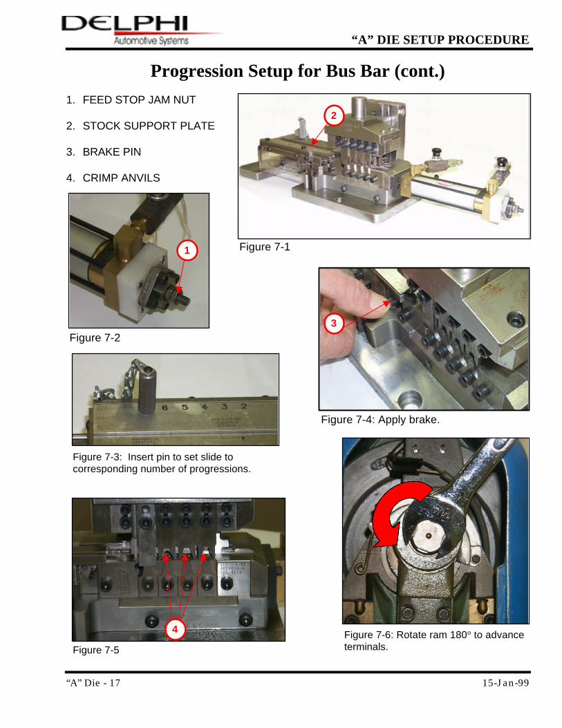
Progression Setup for Bus Bar (cont.)
1. FEED STOP JAM NUT 2. STOCK SUPPORT PLATE 3. BRAKE PIN 4. CRIMP ANVILS
Figure 7-5
Figure 7-6: Rotate ram 180° to advance terminals.
3
Figure 7-3: Insert pin to set slide to corresponding number of progressions.
1 Figure 7-1
Figure 7-2
Figure 7-4: Apply brake.
2
4
“A” Die - 18 15-Jan-99
“A” DIE SETUP PROCEDURE
Crimp Height Setup
Steps Procedure
1. Loosen the two cap screws on the Connecting Rod Clamp (Figure 9-1). 2. Turn Ball Screw Adjustment to the right to increase and to the left to
decrease. 3. Retighten the two cap screws on the Connecting Rod Clamp.
NOTE:
If reinstalling crimp tools, ensure that pockets are clear of debris.
Crimp Height Trouble Shooting
Trouble Possible Cause Correction Crimp height changes in the middle of the run.
Crimp Height adjuster not properly tightened and/or Crimp Tools not properly seated.
See Step 3. Remove and reinstall Crimp Tools.
“A” Die - 19 15-Jan-99
“A” DIE SETUP PROCEDURE
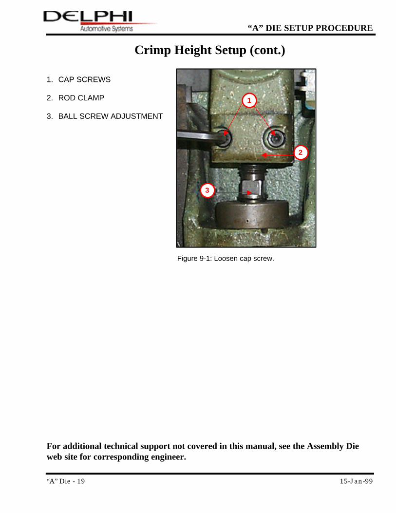
Crimp Height Setup (cont.)
1. CAP SCREWS 2. ROD CLAMP 3. BALL SCREW ADJUSTMENT For additional technical support not covered in this manual, see the Assembly Die web site for corresponding engineer.
Figure 9-1: Loosen cap screw.
3
1
2