Embed Size (px)
Citation preview
1
Original InstructionsRev. 6/11/2015
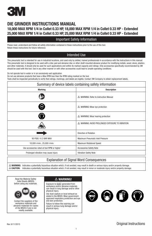
3DIE GRINDER INSTRUCTIONS MANUAL18,000 MAX RPM 1/4 in Collet 0.33 HP, 18,000 MAX RPM 1/4 in Collet 0.33 HP - Extended25,000 MAX RPM 1/4 in Collet 0.33 HP, 25,000 MAX RPM 1/4 in Collet 0.33 HP - Extended
Important Safety InformationPlease read, understand and follow all safety information contained in these instructions prior to the use of this tool.Retain these instructions for future reference.
Intended UseThis pneumatic tool is intended for use in industrial locations, and used only by skilled, trained professionals in accordance with the instructions in this manual. This pneumatic tool is designed to be used with a disc pad and abrasive disc or other shaft mounted abrasive product for modifying metals, wood, stone, plastics and other materials. It should only be used for such applications and within its marked capacity and ratings. Only accessories specifically recommended by 3M should be used with this tool. Use in any other manner or with other accessories could lead to unsafe operating conditions.
Do not operate tool in water or in an excessively wet application.Do not use abrasive products that have a Max RPM less than the RPM rating marked on the tool.Tools shall be inspected periodically to verify that ratings, markings, and labels are legible. Contact 3M Company to obtain replacement labels.
Summary of device labels containing safety informationMarking Description
WARNING: Refer to Instruction Manual
WARNING: Wear eye protection
WARNING: Wear hearing protection
WARNING: AVOID PROLONGED EXPOSURE TO VIBRATION
Direction of Rotation
90 PSIG / 6.2 BAR MAX Maximum Pneumatic Inlet Pressure
18,000 r/min., 25,000 r/min. Maximum Rotational Speed
Use accessories rated at tool RPM or higher Accessories Safety Note
Prolonged vibration may cause injury Vibration Safety Note
Explanation of Signal Word Consequences WARNING: Indicates a potentially hazardous situation which, if not avoided, may result in death or serious injury and/or property damage. CAUTION: Indicates a potentially hazardous situation which, if not avoided, may result in minor or moderate injury and/or property damage.
WARNING!Read the Material SafetyData Sheets (MSDS)
before using any materials.
Contact the suppliers of theworkpiece materials and
abrasive materials for copiesof the MSDS if one is not
readily available.
Exposure to DUST generated fromworkpiece and/or abrasive materialscan result in lung damage and/or other physical injury.Use dust capture or local exhaust as stated in the MSDS. Wear government-approved respiratory protection and eye and skin protection.Failure to follow this warning can result in serious lung damage and/or physical injury.
MSDS

1 2
WARNINGTo reduce the risks associated with impact from abrasive product or tool breakup, sharp edges, hazardous pressure, rupture, vibration and noise:• Read, understand and follow the safety information contained in these instructions prior to the use of this tool. Retain these instructions for future
reference.• Only personnel who are properly trained should be allowed to service this tool.• Practice safety requirements. Work alert, have proper attire, and do not operate tool under the influence of alcohol or drugs.• Operators and other personnel must always wear protection for eyes, ears, and respiratory protection when in the work area or while operating this
product. Follow your employer’s safety policy for PPE’s and/or ANSI Z87.1 or local/national standards for eyewear and other personal protective equipment requirements.
• Wear protective apparel, taking into consideration the type of work being done.• Never exceed marked maximum input pressure (90psi / .62Mpa / 6.2Bars).• Proper eye protection must be worn at all times.• Tool shall not be operated in the presence of bystanders.• If you notice any abnormal noise or vibration when operating the product, immediately discontinue its use and inspect for worn or damaged components.
Correct or replace the suspect component. If abnormal noise or vibration still exists, return the tool to 3M for repair or replacement. Refer to warranty instructions.
• Never operate this tool without all safety features in place and in proper working order.• Never over-ride or disable the safety features of the start-stop control such that it is in the on position.• Make sure the tool is disconnected from its air source before servicing, inspecting, maintaining, cleaning, and before changing abrasive product.• Prior to use, inspect abrasive product and accessories for possible damage. If damaged, replace with new abrasive product and accessories available from 3M.• Only use accessories supplied or recommended by 3M.• Use only with mounting hardware recommended by 3M; check with 3M for mounting hardware requirements.• Always ensure that shaft diameters match internal diameters of the collet inserts.• Maximum operating speed of abrasive products or accessories must be reduced whenever the exposed length of shaft (overhang) is longer than
corresponding 3M approved products.• Always ensure that a minimum of 10mm shaft gripping length is observed.• Never install and use router bits or cutting-off wheels in a die grinder tool (which is unguarded).• Use only with abrasive products not requiring guards according to local, state and federal regulations.• Never allow this tool to be used by children or other untrained people.• Do not leave an unattended tool connected to air source.• Air under pressure can cause severe injury. • Never direct air at yourself or anyone else.
To reduce the risk of all hazards associated with vibration:• If any physical hand/wrist discomfort is experienced, work should be stopped promptly to seek medical attention. Hand, wrist and arm injury may result
from repetitive work, motion and overexposure to vibration.• Hold the tool with a light but safe grip, knowing that the grip must be sufficient to counter reaction forces but that a tight grip will increase the amount of
vibration transferred to the operator.
To reduce the risks associated with loud noise:• Always wear protection for eyes, ears, and respiratory protection while operating this product. Follow your employer’s safety policy for PPE’s and/or ANSI
Z87.1 or local/national standards for eyewear and other personal protective equipment requirements.• Always wear hearing protection while operating this tool. Follow your employer’s safety policy or local/national standards for personal protective
equipment requirements.• Ensure the muffler material is in place. • Dampen work pieces to reduce noise and prevent ringing.
To reduce the risk associated with fire or explosion:• Do not operate the tool in explosive atmospheres, such as in the presence of flammable liquids, gases, or dust. The abrasives are able to create sparks
when working material, resulting in the ignition of the flammable dust or fumes.• Refer to MSDS of material being worked as to potential for creating fire or explosion hazard.
To reduce the risk associated with hazardous dust ingestion or eye/skin exposure:• Use appropriate respiratory and skin protection, or local exhaust as stated in the MSDS of the material being worked on.• Direct exhaust so as to minimize disturbance of existing dust in a dust-filled environment.
To reduce the risk associated with hazardous voltage:• Do not allow this tool to come into contact with electrical power sources as the tool is not insulated against electrical shock.
CAUTIONTo reduce the risk associated with skin abrasion, burns, cuts, or entrapment:• Keep hands, hair, and clothing away from the rotating part of the tool.• Wear suitable protective gloves while operating tool.• Do not touch the rotating parts during operation for any reason.• Do not force tool or use excessive force when using tool.
To reduce the risk associated with whipping or hazardous pressure-rupture:• Ensure supply hose is oil resistant and is properly rated for required working pressure.• Do not use tools with loose or damaged air hoses or fittings.• Be aware that incorrectly installed hoses and fittings might unexpectedly come loose at any time and create a whipping/impact hazard.• Whenever universal twist couplings (claw couplings) are used, lock-pins shall be installed and whip check safety cables shall be used to safeguard
against possible hose-to-tool and hose-to-hose connection failure.
To reduce the risk associated with fly off of abrasive product or parts:• Use care in attaching abrasive product and mounting hardware; following the instructions to ensure that they are securely attached to the tool before use
or free-spinning.• Never point this product in the direction of yourself or another person, or start tool unintentionally.• Never over-tighten accessory fasteners.
3
Parts Page
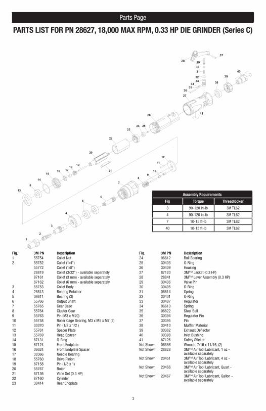
PARTS LIST FOR PN 28627, 18,000 MAX RPM, 0.33 HP DIE GRINDER (Series C)
Fig. 3M PN Description1 55754 Collet Nut2 55752 Collet (1/4")
55772 Collet (1/8")28819 Collet (3/32") - available separately87161 Collet (3 mm) - available separately87162 Collet (6 mm) - available separately
3 55753 Collet Body4 28813 Bearing Retainer5 06611 Bearing (3)6 55766 Output Shaft7 55765 Gear Case8 55764 Cluster Gear9 55763 Pin (M3 x M20)10 55758 Roller Cage Bearing, M3 x M5 x M7 (2)11 30370 Pin (1/8 x 1/2 )12 55761 Spacer Plate13 55769 Head Spacer14 87131 O-Ring15 87124 Front Endplate16 06624 Front Endplate Spacer17 30366 Needle Bearing 18 55760 Drive Pinion19 87158 Pin (1/8 x 1)20 55767 Rotor21 87136 Vane Set (0.3 HP)22 87160 Cylinder23 30414 Rear Endplate
Fig. 3M PN Description24 06612 Ball Bearing25 30403 O-Ring26 30409 Housing27 87120 3M™ Jacket (0.3 HP)28 28841 3M™ Lever Assembly (0.3 HP)29 30406 Valve Pin30 30405 O-Ring31 06614 Spring32 30401 O-Ring33 30407 Regulator34 06613 Spring35 06622 Steel Ball36 30394 Regulator Pin37 30395 Pin38 30410 Muffler Material39 30382 Exhaust Deflector40 30398 Inlet Bushing41 87126 Safety StickerNot Shown 06586 Wrench, 7/16 x 11/16, (2)Not Shown 28828 3M™ Air Tool Lubricant, 1 oz -
available separatelyNot Shown 20451 3M™ Air Tool Lubricant, 4 oz -
available separatelyNot Shown 20466 3M™ Air Tool Lubricant, Quart -
available separatelyNot Shown 20467 3M™ Air Tool Lubricant, Gallon -
available separately
14
1516 17
1821
19
20
22
2324 25
26
27
28
1
2
3
56
10
11
12
13
98
7
293031
3233
3435
36
37
38
3940
4
5
41
Assembly Requirements
Fig Torque Threadlocker
3 90-120 in-lb 3M TL62
4 90-120 in-lb 3M TL62
7 10-15 ft-lb 3M TL62
40 10-15 ft-lb 3M TL62
3 4
Parts Page
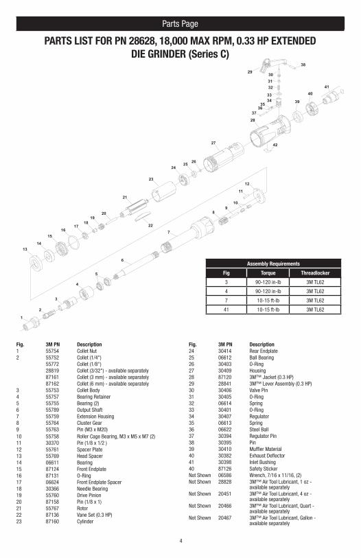
PARTS LIST FOR PN 28628, 18,000 MAX RPM, 0.33 HP EXTENDED DIE GRINDER (Series C)
Fig. 3M PN Description1 55754 Collet Nut2 55752 Collet (1/4")
55772 Collet (1/8")28819 Collet (3/32") - available separately87161 Collet (3 mm) - available separately87162 Collet (6 mm) - available separately
3 55753 Collet Body4 55757 Bearing Retainer5 55755 Bearing (2)6 55789 Output Shaft7 55759 Extension Housing8 55764 Cluster Gear9 55763 Pin (M3 x M20)10 55758 Roller Cage Bearing, M3 x M5 x M7 (2)11 30370 Pin (1/8 x 1/2 )12 55761 Spacer Plate13 55769 Head Spacer14 06611 Bearing15 87124 Front Endplate16 87131 O-Ring17 06624 Front Endplate Spacer18 30366 Needle Bearing 19 55760 Drive Pinion20 87158 Pin (1/8 x 1)21 55767 Rotor22 87136 Vane Set (0.3 HP)23 87160 Cylinder
Fig. 3M PN Description24 30414 Rear Endplate25 06612 Ball Bearing26 30403 O-Ring27 30409 Housing28 87120 3M™ Jacket (0.3 HP)29 28841 3M™ Lever Assembly (0.3 HP)30 30406 Valve Pin31 30405 O-Ring32 06614 Spring33 30401 O-Ring34 30407 Regulator35 06613 Spring36 06622 Steel Ball37 30394 Regulator Pin38 30395 Pin39 30410 Muffler Material40 30382 Exhaust Deflector41 30398 Inlet Bushing40 87126 Safety StickerNot Shown 06586 Wrench, 7/16 x 11/16, (2)Not Shown 28828 3M™ Air Tool Lubricant, 1 oz -
available separatelyNot Shown 20451 3M™ Air Tool Lubricant, 4 oz -
available separatelyNot Shown 20466 3M™ Air Tool Lubricant, Quart -
available separatelyNot Shown 20467 3M™ Air Tool Lubricant, Gallon -
available separately
28
1
2
3
10
11
12
98
29 303132
3334
3536
37
38
39
40
4
5
6
7
1314
1516
1718
1920
21
22
23
2425 26
27
41
42
Assembly Requirements
Fig Torque Threadlocker
3 90-120 in-lb 3M TL62
4 90-120 in-lb 3M TL62
7 10-15 ft-lb 3M TL62
41 10-15 ft-lb 3M TL62
5
Parts Page
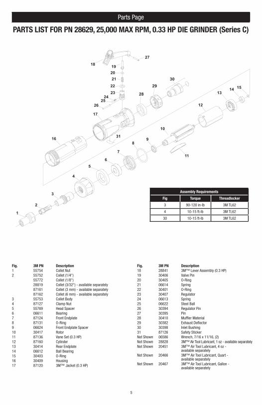
PARTS LIST FOR PN 28629, 25,000 MAX RPM, 0.33 HP DIE GRINDER (Series C)
Fig. 3M PN Description1 55754 Collet Nut2 55752 Collet (1/4")
55772 Collet (1/8")28819 Collet (3/32") - available separately87161 Collet (3 mm) - available separately87162 Collet (6 mm) - available separately
3 55753 Collet Body4 87127 Clamp Nut5 55769 Head Spacer6 06611 Bearing7 87124 Front Endplate8 87131 O-Ring9 06624 Front Endplate Spacer10 30417 Rotor11 87136 Vane Set (0.3 HP)12 87160 Cylinder13 30414 Rear Endplate14 06612 Ball Bearing15 30403 O-Ring16 30409 Housing17 87120 3M™ Jacket (0.3 HP)
Fig. 3M PN Description18 28841 3M™ Lever Assembly (0.3 HP)19 30406 Valve Pin20 30405 O-Ring21 06614 Spring22 30401 O-Ring23 30407 Regulator24 06613 Spring25 06622 Steel Ball26 30394 Regulator Pin27 30395 Pin28 30410 Muffler Material29 30382 Exhaust Deflector30 30398 Inlet Bushing31 87126 Safety StickerNot Shown 06586 Wrench, 7/16 x 11/16, (2)Not Shown 28828 3M™ Air Tool Lubricant, 1 oz - available separatelyNot Shown 20451 3M™ Air Tool Lubricant, 4 oz -
available separatelyNot Shown 20466 3M™ Air Tool Lubricant, Quart -
available separatelyNot Shown 20467 3M™ Air Tool Lubricant, Gallon -
available separately
28
1
2
3
8
2930
4
56
7
1314 15
16
17
18 192021
10
2324
2526
9
11
12
22
27
31
Assembly Requirements
Fig Torque Threadlocker
3 90-120 in-lb 3M TL62
4 10-15 ft-lb 3M TL62
30 10-15 ft-lb 3M TL62
5 6
Parts Page
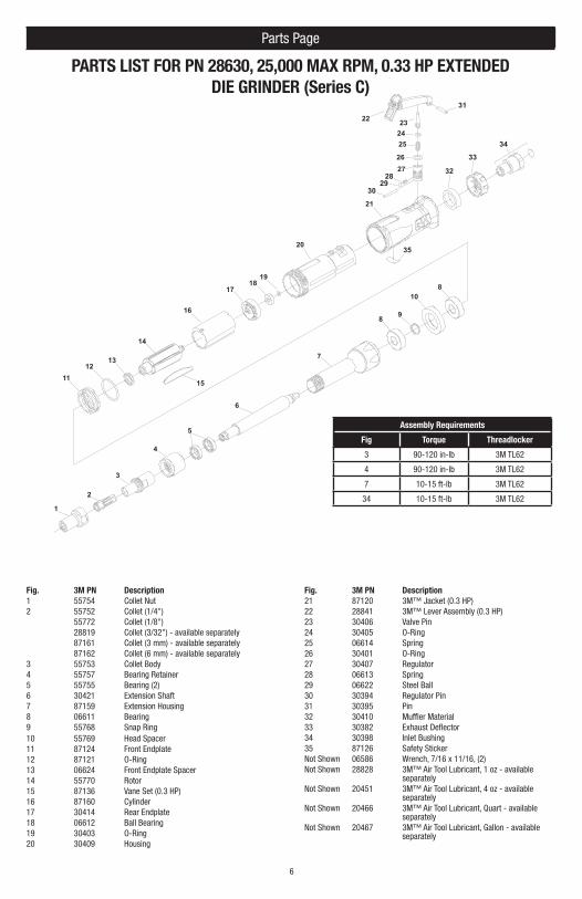
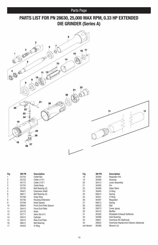
PARTS LIST FOR PN 28630, 25,000 MAX RPM, 0.33 HP EXTENDED DIE GRINDER (Series C)
Fig. 3M PN Description1 55754 Collet Nut2 55752 Collet (1/4")
55772 Collet (1/8")28819 Collet (3/32") - available separately87161 Collet (3 mm) - available separately87162 Collet (6 mm) - available separately
3 55753 Collet Body4 55757 Bearing Retainer5 55755 Bearing (2)6 30421 Extension Shaft7 87159 Extension Housing8 06611 Bearing9 55768 Snap Ring10 55769 Head Spacer11 87124 Front Endplate12 87121 O-Ring13 06624 Front Endplate Spacer14 55770 Rotor15 87136 Vane Set (0.3 HP)16 87160 Cylinder17 30414 Rear Endplate18 06612 Ball Bearing19 30403 O-Ring20 30409 Housing
Fig. 3M PN Description21 87120 3M™ Jacket (0.3 HP)22 28841 3M™ Lever Assembly (0.3 HP)23 30406 Valve Pin24 30405 O-Ring25 06614 Spring26 30401 O-Ring27 30407 Regulator28 06613 Spring29 06622 Steel Ball30 30394 Regulator Pin31 30395 Pin32 30410 Muffler Material33 30382 Exhaust Deflector34 30398 Inlet Bushing35 87126 Safety StickerNot Shown 06586 Wrench, 7/16 x 11/16, (2)Not Shown 28828 3M™ Air Tool Lubricant, 1 oz - available
separatelyNot Shown 20451 3M™ Air Tool Lubricant, 4 oz - available
separatelyNot Shown 20466 3M™ Air Tool Lubricant, Quart - available
separatelyNot Shown 20467 3M™ Air Tool Lubricant, Gallon - available
separately
28
1
2
3
10
98
2930
31
32
4
5
6
713
14
15
16
1718
19
20
21
22 232425
2627
8
1112
34
33
35
Assembly Requirements
Fig Torque Threadlocker
3 90-120 in-lb 3M TL62
4 90-120 in-lb 3M TL62
7 10-15 ft-lb 3M TL62
34 10-15 ft-lb 3M TL62

7
Parts Page
PARTS LIST FOR PN 28627, 18,000 MAX RPM, 0.33 HP DIE GRINDER (Series A)
Fig 3M PN Description1 55754 Collet Nut 2 55752 Collet (1/4") 2 55772 Collet (1/8") 3 55753 Collet Body 4 28813 Bearing Retainer5 06611 Ball Bearing (2)6 55766 Output Shaft7 55765 Gear Case8 55764 Cluster Gear9 55763 Pin M3 x M2010 55758 Roller Cage Bearing M3 x M5 x M7 (2)11 30370 Pin12 55761 Spacer Plate13 55769 Head Spacer14 06624 Front End Plate Spacer15 30413 Front End Plate16 30366 Needle Bearing17 55760 Drive Pinion18 55762 Pin 1/8 x 1-1/819 55767 Rotor20 55771 Vane Set of 521 30415 Cylinder
Fig 3M PN Description22 30414 Rear End Plate23 06612 Ball Bearing24 30403 O-Ring25 30394 Regulator Pin26 30409 Housing27 30412 Lever Assembly28 30395 Pin29 30406 Valve Stem30 30405 O-Ring31 06614 Spring32 30401 O-Ring33 30407 Regulator34 06613 Spring35 06622 Ball36 28573 Cover (gray)37 30410 Muffler38 30382 Rotatable Exhaust Deflector 39 30398 Inlet Bushing40 28651 Overhose Kit (Optional)41 28652 Overhose Replacment Sleeve (Optional)not shown 06586 Wrench (2)
USE 3M TL62 THREADLOCKER TO 10-15 FT-LB
USE 3M TL62 THREADLOCKER TO 90-120 IN-LB
USE 3M TL62 THREADLOCKER TO 10-15 FT-LB
LUBRICATE GEARS WITH APPROX. .05 OZ OF FUCHS RENOLIT A X S2 OR EQUAL
TO 90-120 IN-LB

7 8
Parts Page
PARTS LIST FOR PN 28628, 18,000 MAX RPM, 0.33 HP EXTENDED DIE GRINDER (Series A)
41 42
Fig 3M PN Description1 55754 Collet Nut 2 55752 Collet (1/4") 2 55772 Collet (1/8") 3 55753 Collet Body 4 55757 Bearing Retainer5 55755 Ball Bearing (2)6 55789 Output Shaft7 55759 Housing Extension8 55764 Cluster Gear9 55763 Pin M3 x M2010 55758 Roller Cage Bearing M3 x M5 x M7 (2)11 30370 Pin12 55761 Spacer Plate13 55769 Head Spacer14 06611 Ball Bearing15 06624 Front End Plate Spacer16 30413 Front End Plate17 30366 Needle Bearing18 55760 Drive Pinion19 55762 Pin 1/8 x 1-1/820 55767 Rotor21 55771 Vane Set of 5
Fig 3M PN Description22 30415 Cylinder23 30414 Rear End Plate24 06612 Ball Bearing25 30403 O-Ring26 30394 Regulator Pin27 30409 Housing28 30412 Lever Assembly29 30395 Pin30 30406 Valve Stem31 30405 O-Ring32 06614 Spring33 30401 O-Ring34 30407 Regulator35 06613 Spring36 06622 Ball37 28573 Cover (gray)38 30410 Muffler39 30382 Rotatable Exhaust Deflector 0.3 HP40 30398 Inlet Bushing41 28651 Overhose Kit (Optional)42 28652 Overhose Replacment Sleeve (Optional)not shown 06586 Wrench (2)
29
28
27
26
16
15
1314
12
21
22
2523
24
30
3132
33
34
3536
37
38
3940
910
11
17
19
20
18
6
7 8
54
12
3

9
Parts Page
PARTS LIST FOR PN 28629, 25,000 MAX RPM, 0.33 HP DIE GRINDER (Series A)
30 31
Fig 3M PN Description1 55754 Collet Nut 2 55752 Collet (1/4") 2 55772 Collet (1/8") 3 55753 Collet Body 4 30411 Clamp Nut5 55769 Head Spacer6 06611 Ball Bearing7 06624 Front End Plate Spacer8 30413 Front End Plate9 30417 Rotor10 55771 Vane Set of 511 30415 Cylinder12 30414 Rear End Plate13 06612 Ball Bearing14 30403 O-Ring15 30394 Regulator Pin16 30409 Housing
Fig 3M PN Description17 30412 Lever Assembly18 30395 Pin19 30406 Valve Stem20 30405 O-Ring21 06614 Spring22 30401 O-Ring23 30407 Regulator24 06613 Spring25 06622 Ball26 28573 Cover (gray)27 30410 Muffler28 30382 Rotatable Exhaust Deflector29 30398 Inlet Bushing30 28651 Overhose Kit (Optional)31 28652 Overhose Replacment Sleeve (Optional)not shown 06586 Wrench (2)
2928
27
26
12
25
8
4
6
9
10
11
16
17
18
13
15
14
5
12
3
7
21
22
20
23
24
19
9 10
Parts Page
PARTS LIST FOR PN 28630, 25,000 MAX RPM, 0.33 HP EXTENDED DIE GRINDER (Series A)
33 34
Fig 3M PN Description1 55753 Collet Nut 2 55752 Collet (1/4") 2 55772 Collet (1/8") 3 55752 Collet Body 4 55755 Ball Bearing (2)5 30421 Extension Shaft6 06611 Ball Bearing (2)7 55768 Snap Ring8 55756 Housing Extension9 55769 Head Spacer10 06624 Front End Plate Spacer11 30413 Front End Plate12 55770 Rotor13 55771 Vane Set of 514 30415 Cylinder15 30414 Rear End Plate16 06612 Ball Bearing17 30403 O-Ring
Fig 3M PN Description18 30394 Regulator Pin19 30409 Housing20 30412 Lever Assembly21 30395 Pin22 30406 Valve Stem23 30405 O-Ring24 06614 Spring25 30401 O-Ring26 30407 Regulator27 06613 Spring28 06622 Ball29 28573 Cover (gray)30 30410 Muffler31 30382 Rotatable Exhaust Deflector 32 30398 Inlet Bushing33 28651 Overhose Kit (Optional)34 28652 Overhose Replacment Sleeve (Optional)not shown 06586 Wrench (2)
26
13
12
21
22
25
2324
9
10
11
19
20
18
6 7
4
8
12
3
1615
14
17
29
2827
3132
30
5
6
11
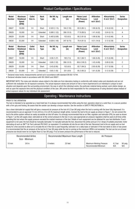
Product Configuration / Specifications
Model Number
Maximum Rotational
Speed (RPM)
Collet Size in.
Neck Type
Net Wt. kg (lb)
Length mm (in)
*Noise Level dBA Pressure
(Power)
#Vibration Level
m/s2 (ft/s2)
#Uncertainty K m/s2 (ft/s2)
Series Designation
28627 18,000 1/4 Short 0.522 (1.15) 184 (7.25) 83.5 (95.1) 1.90 (6.23) 0.16 (0.52) A
28628 18,000 1/4 Extended 0.690 (1.52) 266 (10.5) 77.9 (89.5) 1.41 (4.62) 0.04 (0.13) A
28629 25,000 1/4 Short 0.405 (0.89) 152 (6.0) 80.2 (91.8) 1.98 (6.56) 0.14 (0.46) A
28630 25,000 1/4 Extended 0.639 (1.40) 247 (9.75) 79.4 (91.0) 4.51 (14.8) 0.12 (0.39) A
Model Number
Maximum Rotational
Speed (RPM)
Collet Size in.
Neck Type
Net Wt. kg (lb)
Length mm (in)
*Noise Level dBA Pressure
(Power)
#Vibration Level
m/s2 (ft/s2)
#Uncertainty K m/s2 (ft/s2)
Series Designation
28627 18,000 1/4 Short 0.58 (1.27) 192 (7.5) 83.1 (94.7) 1.66 (5.45) 0.15 (0.49) C
28628 18,000 1/4 Extended 0.69 (1.52) 266 (10.5) 88.6 (100.2) 1.43 (4.69) 0.09 (0.30) C
28629 25,000 1/4 Short 0.43 (0.95) 152 (6.0) 82.7 (94.3) 2.83 (9.28) 0.17 (0.56) C
28630 25,000 1/4 Extended 0.65 (1.43) 251 (9.9) 85.3 (95.2) 1.61 (5.28) 0.12 (0.39) C
* Declared noise levels; measurements carried out in accordance with standard EN ISO 15744.# Declared vibration levels in accordance with ISO 20643 and 28927.
IMPORTANT NOTE: The noise and vibration values stated in the table are from laboratory testing in conformity with stated codes and standards and are not sufficient risk evaluation for all exposure scenarios. The actual exposure values and amount of risk or harm experienced to an individual is unique to each situation and depends upon the surrounding environment, the way in which the individual works, the particular material being worked, work station design, as well as upon the exposure time and the physical condition of the user. 3M cannot be held responsible for the consequences of using declared values instead of actual exposure values for any individual risk assessment.
Operating / Maintenance InstructionsPRIOR TO THE OPERATIONThe tool is intended to be operated as a hand held tool. It is always recommended that while using the tool, operators stand on a solid floor, in a secure position with a firm grip and footing. Be aware that the sander can develop a torque reaction. See the section in SAFETY PRECAUTIONS in.
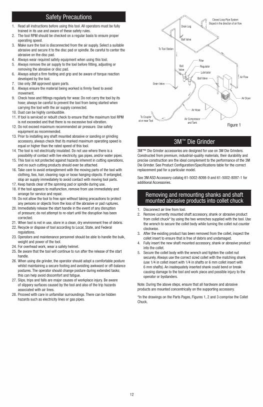
Use a clean lubricated air supply that will give a measured air pressure at the tool of 6.2 bar (90 psig) when the tool is running with the lever fully depressed. It is recommended to use an approved 10 mm (3/8 in) x 8 m (25 ft) maximum length airline. Connect the tool to the air supply as shown in Figure 1. Do not connect the tool to the airline system without an easily accessible air shut off valve. It is strongly recommended that an air filter, regulator and lubricator (FRL) be used as shown in Figure 1 as this will supply clean, lubricated air at the correct pressure to the tool. In any case appropriate air pressure regulators shall be used at all times while operating this tool where the supply pressure exceeds the marked maximum of the tool. Details of such equipment can be obtained for your tool distributor. If such equipment is not used, the tool should be manually lubricated. To manually lubricate the tool, disconnect the airline and put 2 to 3 drops of suitable pneumatic motor lubricating oil such as 3M™ Air Tool Lubricant PN 20451 (or equivalent 10 centistoke oil) into the air inlet of the tool. Reconnect tool to the air supply and run tool slowly for a few seconds to allow air to circulate the oil. If the tool is used frequently, lubricate it on a daily basis or lubricate it if the tool starts to slow or lose power. It is recommended that the air pressure at the tool be 6.2 bar (90 psig) while the tool is running so the maximum RPM is not exceeded. The tool can be run at lower pressures but should never be run higher than 6.2 bar (90 psig). If run at lower pressure the performance of the tool is reduced.
Recommended AirlineSize - Minimum
Recommended Maximum Hose Length Air Pressure
10 mm 3/8 in 8 meters 25 feet Maximum Working PressureRecommended Minimum
6.2 barN/A
90 psigN/A
11 12
Safety Precautions1. Read all instructions before using this tool. All operators must be fully
trained in its use and aware of these safety rules.2. The tool RPM should be checked on a regular basis to ensure proper
operating speed.3. Make sure the tool is disconnected from the air supply. Select a suitable
abrasive and secure it to the disc pad or spindle. Be careful to center the abrasive on the disc pad.
4. Always wear required safety equipment when using this tool.5. Always remove the air supply to the tool before fitting, adjusting or
removing the abrasive or disc pad.6. Always adopt a firm footing and grip and be aware of torque reaction
developed by the tool.7. Use only 3M approved spare parts.8. Always ensure the material being worked is firmly fixed to avoid
movement.9. Check hose and fittings regularly for wear. Do not carry the tool by its
hose; always be careful to prevent the tool from being started when carrying the tool with the air supply connected.
10. Dust can be highly combustible.11. If tool is serviced or rebuilt check to ensure that the maximum tool RPM
is not exceeded and that there is no excessive tool vibration.12. Do not exceed maximum recommended air pressure. Use safety
equipment as recommended.13. Prior to installing any shaft mounted abrasive or sanding or grinding
accessory, always check that its marked maximum operating speed is equal or higher than the rated speed of this tool.
14. The tool is not electrically insulated. Do not use where there is a possibility of contact with live electricity, gas pipes, and/or water pipes.
15. This tool is not protected against hazards inherent in cutting operations, and no such cutting products should ever be attached.
16. Take care to avoid entanglement with the moving parts of the tool with clothing, ties, hair, cleaning rags or loose hanging objects. If entangled, stop air supply immediately to avoid contact with moving tool parts.
17. Keep hands clear of the spinning pad or spindle during use.18. If the tool appears to malfunction, remove from use immediately and
arrange for service and repair.19. Do not allow the tool to free spin without taking precautions to protect
any persons or objects from the loss of the abrasive or pad ruptures.20. Immediately release the start handle in the event of any disruption
of pressure; do not attempt to re-start until the disruption has been corrected.
21. When tool is not in use, store in a clean, dry environment free of debris.22. Recycle or dispose of tool according to Local, State, and Federal
regulations.23. Operators and maintenance personnel should be able to handle the bulk,
weight and power of the tool. 24. For overhead work, wear a safety helmet.25. Be aware that the tool will continue to run after the release of the start
handle. 26. When using die grinder, the operator should adopt a comfortable posture
whilst maintaining a secure footing and avoiding awkward or off-balance postures. The operator should change posture during extended tasks; this can help avoid discomfort and fatigue.
27. Slips, trips and falls are major causes of workplace injury. Be aware of slippery surfaces caused by the tool and also of the trip hazards associated with air lines.
28. Proceed with care in unfamiliar surroundings. There can be hidden hazards such as electricity lines or gas pipes.
3M™ Die Grinder3M™ Die Grinder accessories are designed for use on 3M Die Grinders. Constructed from premium, industrial-quality materials, their durability and precise construction are the ideal complement to the performance of the 3M Die Grinder. See Product Configuration/Specifications table for the correct replacement pad for a particular model.
See 3M ASD Accessory catalog 61-5002-8098-9 and 61-5002-8097-1 for additional Accessories.
Removing and remounting shanks and shaft mounted abrasive products into collet chuck
1. Disconnect air line from tool.2. Remove currently mounted shaft accessory, shank or abrasive product
from collet chuck* by using the two wrenches supplied with the tool. Use the wrench to secure the collet body while turning the collet nut counter clockwise.
3. After the existing product has been removed from the collet, inspect the collet insert to ensure that is free of debris and undamaged.
4. Fully insert the new shaft mounted accessory, shank or abrasive product into the collet.
5. Secure the collet body with the wrench and tighten the collet nut securely. Always use the correct sized collet with the matching shank (use 1/4 in collet insert with 1/4 in shafts or 6 mm collet insert with 6 mm shafts). An inadequately inserted shank could bend or break causing damage to the tool and work piece and possible injury to the operator or bystanders.
Note: During the above steps, ensure that all hardware and abrasive products are mounted concentrically on the supporting accessory.
*In the drawings on the Parts Pages, Figures 1, 2 and 3 comprise the Collet Chuck.
Figure 1
Closed Loop Pipe SystemSloped in the direction of air flow
Drain Leg
Ball Valve
To Tool Station
Filter
Drain Valve
Regulator
Lubricator
BallValve
Ball Valve Air Flow
Air Dryer
Air Compressorand Tank
Air Hose
To Couplerat or near Tool
13
Product Use: All statements, technical information and recommendations contained in this document are based up on tests or experience that 3M believes are reliable. However, many factors beyond 3M’s control can affect the use and performance of a 3M product in a particular application, including the conditions under which the 3M product is used and the time and environmental conditions in which the product is expected to perform. Since these factors are uniquely within the user’s knowledge and control, it is essential that the user evaluate the 3M product to determine whether it is fit for a particular purpose and suitable for the user’s method of application.Warranty and Limited Remedy: 3M warrants this tool against defects in workmanship and materials under normal operating conditions for one (1) year from the date of purchase. 3M MAKES NO OTHER WARRANTIES, EXPRESS OR IMPLIED, INCLUDING, BUT NOT LIMITED TO, ANY IMPLIED WARRANTY OF MERCHANTABILITY OR FITNESS FOR A PARTICULAR PURPOSE OR ANY IMPLIED WARRANTY ARISING OUT OF A COURSE OF DEALING, CUSTOM OR USAGE OF TRADE. User is responsible for determining whether the 3M tool is fit for a particular purpose and suitable for user’s application. User must operate the tool in accordance with all applicable operating instructions, safety precautions, and other procedures stated in the operating manual to be entitled to warranty coverage. 3M shall have no obligation to repair or replace any tool or part that fails due to normal wear, inadequate or improper maintenance, inadequate cleaning, non-lubrication, improper operating environment, improper utilities, operator error or misuse, alteration or modification, mishandling, lack of reasonable care, or due to any
accidental cause. If a tool or any part thereof is defective within this warranty period, your exclusive remedy and 3M’s sole obligation will be, at 3M’s option, to repair or replace the tool or refund the purchase price.Limitation of Liability: Except where prohibited by law, 3M will not be liable for any loss or damage arising from the 3M product, whether direct, indirect, special, incidental or consequential, regardless of the legal theory asserted, including warranty, contract, negligence or strict liability.Submitting a Warranty Claim: Contact your dealer when submitting a warranty claim in accordance with the restrictions listed above. Please note that all warranty claims are subject to manufacturer’s approval. Be sure to keep your sales receipt in a safe place. This must be submitted when filing a warranty claim, within 1 year from the date of purchase. For additional assistance call 1-800-362-3550.Product Repair after Warranty Has Expired: Repair of 3M Abrasive Power tools that are not under warranty is available through 3M or a 3M Authorized Tool Repair Representative. Contact your 3M Abrasive Power Tool Distributor for details, or call 1-800-362-3550.
For 3M Product Information Call:800-3M HELPS (800-364-3577) toll free651-737-6501 direct dial
3Abrasive Systems Division3M CenterSt. Paul, MN 55144-1000www.3M.com/abrasives
© 3M 2015.3M is a trademark of 3M Company.
34-8710-0407-2