Embed Size (px)
Citation preview

Diamond System BuilderHandbook
2
Diamond System Builder
User Handbook
Diamond System Builder
3User Handbook
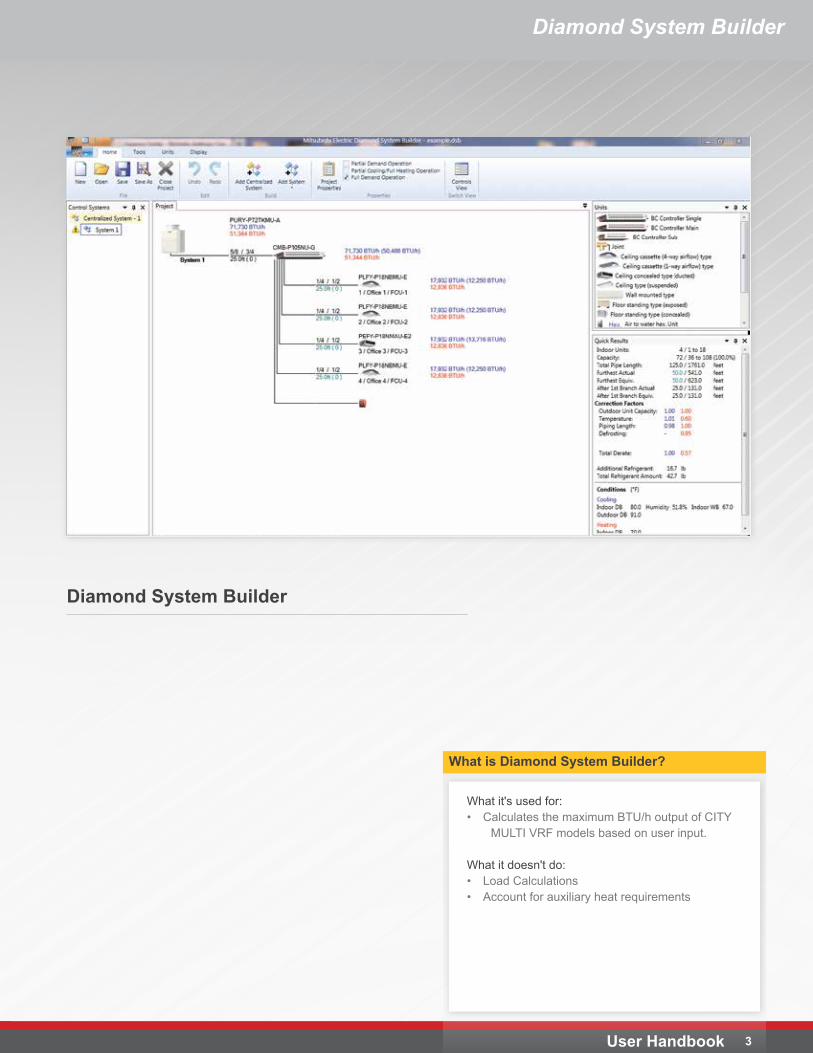
What it's used for:• Calculates the maximum BTU/h output of CITY
MULTI VRF models based on user input.
What it doesn't do:• Load Calculations• Account for auxiliary heat requirements
What is Diamond System Builder?
Diamond System Builder
Diamond System Builder
User Handbook 4
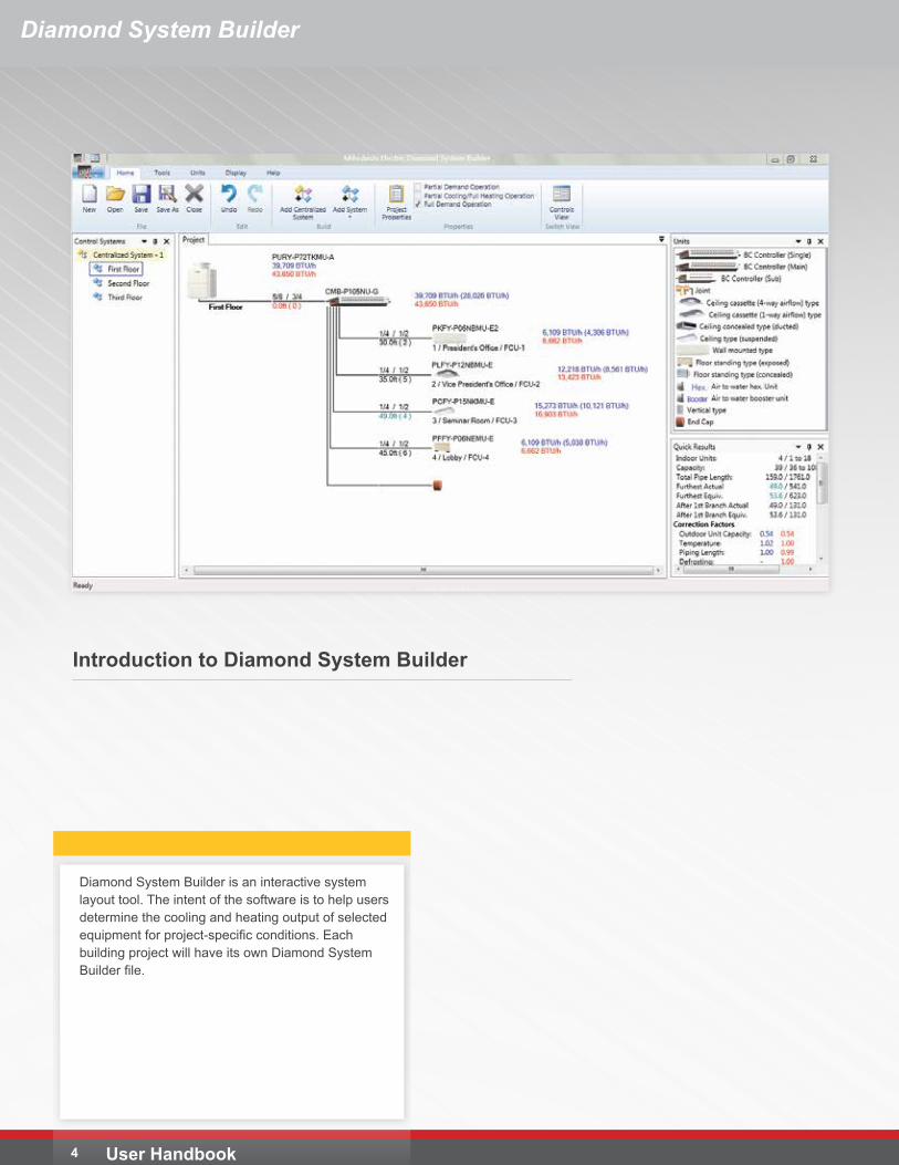
Introduction to Diamond System Builder
Diamond System Builder is an interactive system layout tool. The intent of the software is to help users determine the cooling and heating output of selected equipment for project-specific conditions. Each building project will have its own Diamond System Builder file.
Diamond System Builder
5User Handbook
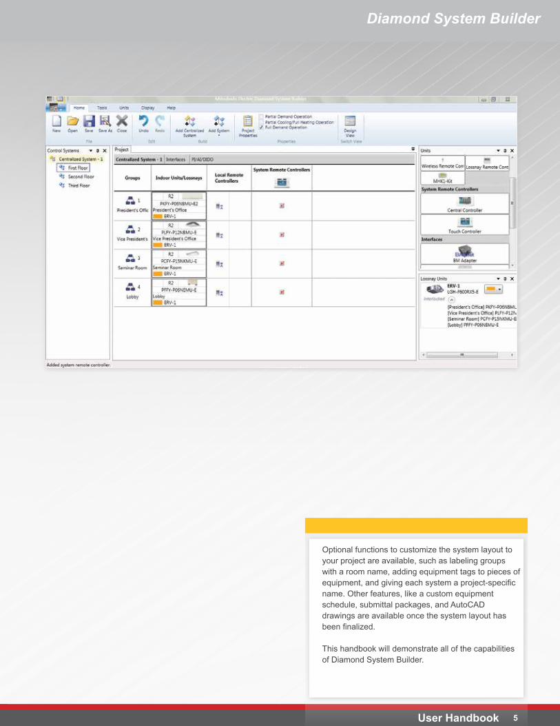
Optional functions to customize the system layout to your project are available, such as labeling groups with a room name, adding equipment tags to pieces of equipment, and giving each system a project-specific name. Other features, like a custom equipment schedule, submittal packages, and AutoCAD drawings are available once the system layout has been finalized.
This handbook will demonstrate all of the capabilities of Diamond System Builder.
Diamond System Builder
User Handbook 6
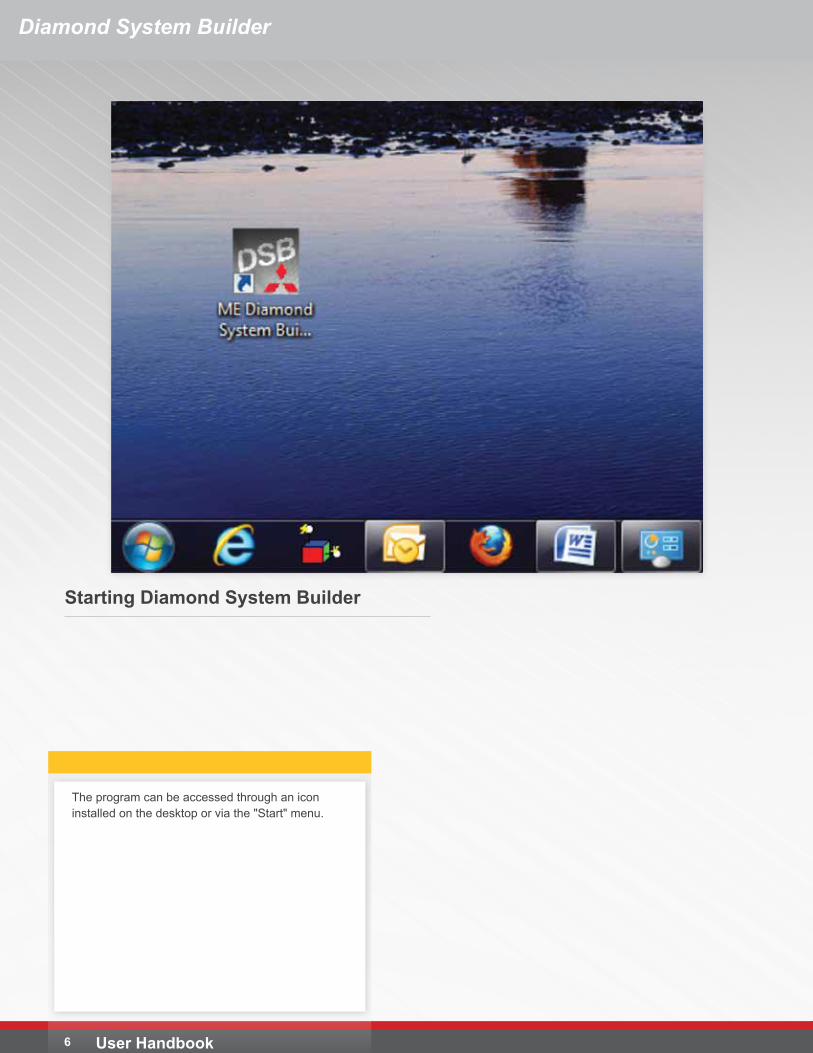
Starting Diamond System Builder
The program can be accessed through an icon installed on the desktop or via the "Start" menu.
Diamond System Builder
7User Handbook
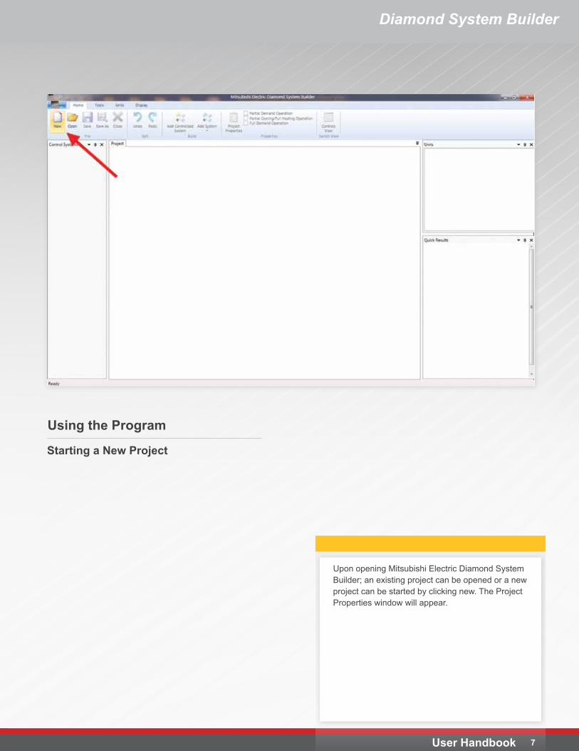
Using the Program
Upon opening Mitsubishi Electric Diamond System Builder; an existing project can be opened or a new project can be started by clicking new. The Project Properties window will appear.
Starting a New Project
Diamond System Builder
User Handbook 8
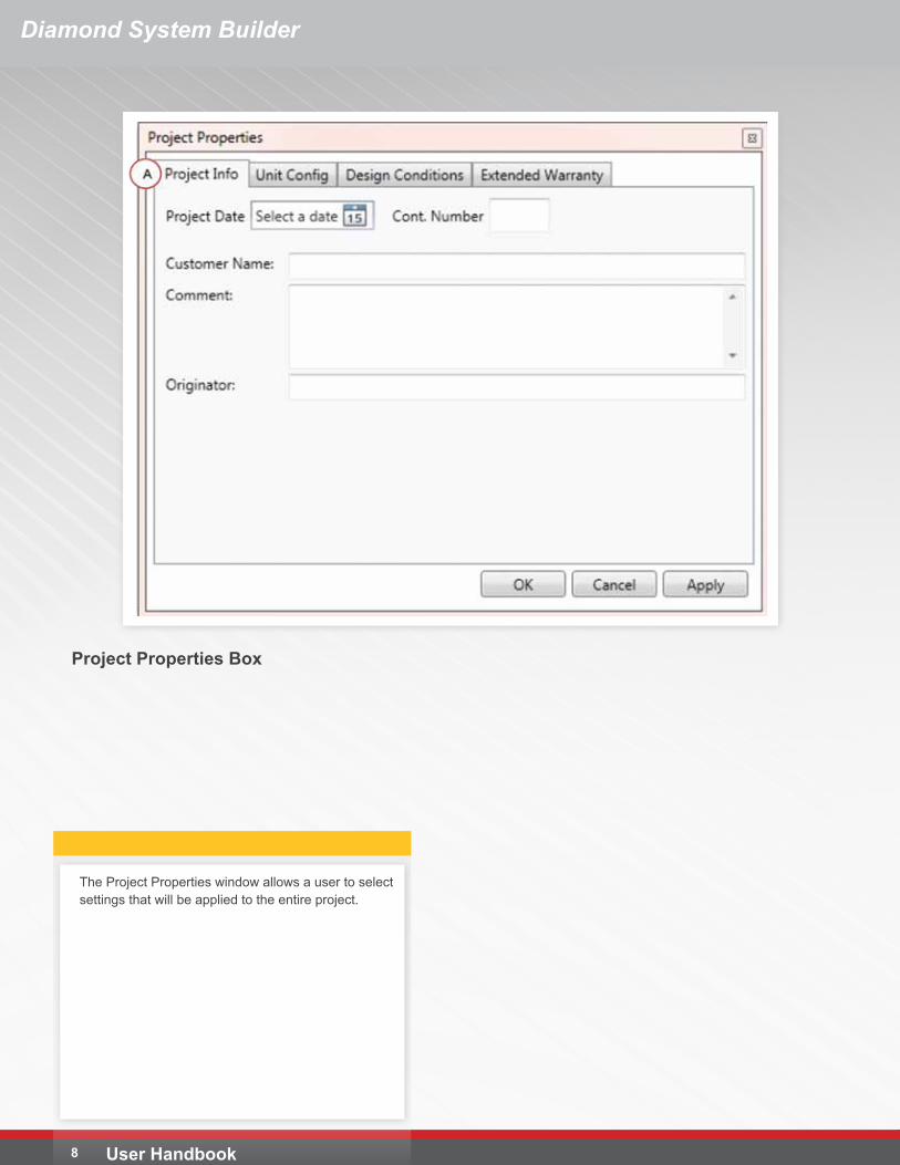
Project Properties Box
The Project Properties window allows a user to select settings that will be applied to the entire project.
Diamond System Builder
9User Handbook
Project Properties BoxA. Project Info Tab
• To change the project date, click the calendar icon and select it from the calendar or type it in manually. This date can be shown on the AutoCAD output drawing.
• Cont No can be used for project numbers, contract numbers, or any other designating number. No input is required.
• Customer Name can be used to input a specific person or organization name. This data can be shown on the AutoCAD output drawing.
• Comment can be used for additional information about the project. This data is shown under the REMARKS area on the AutoCAD output drawing.
• Originator is typically used to identify the person or organization responsible for creating the Diamond System Builder file. This data is displayed on the AutoCAD drawing.
Diamond System Builder
User Handbook 10
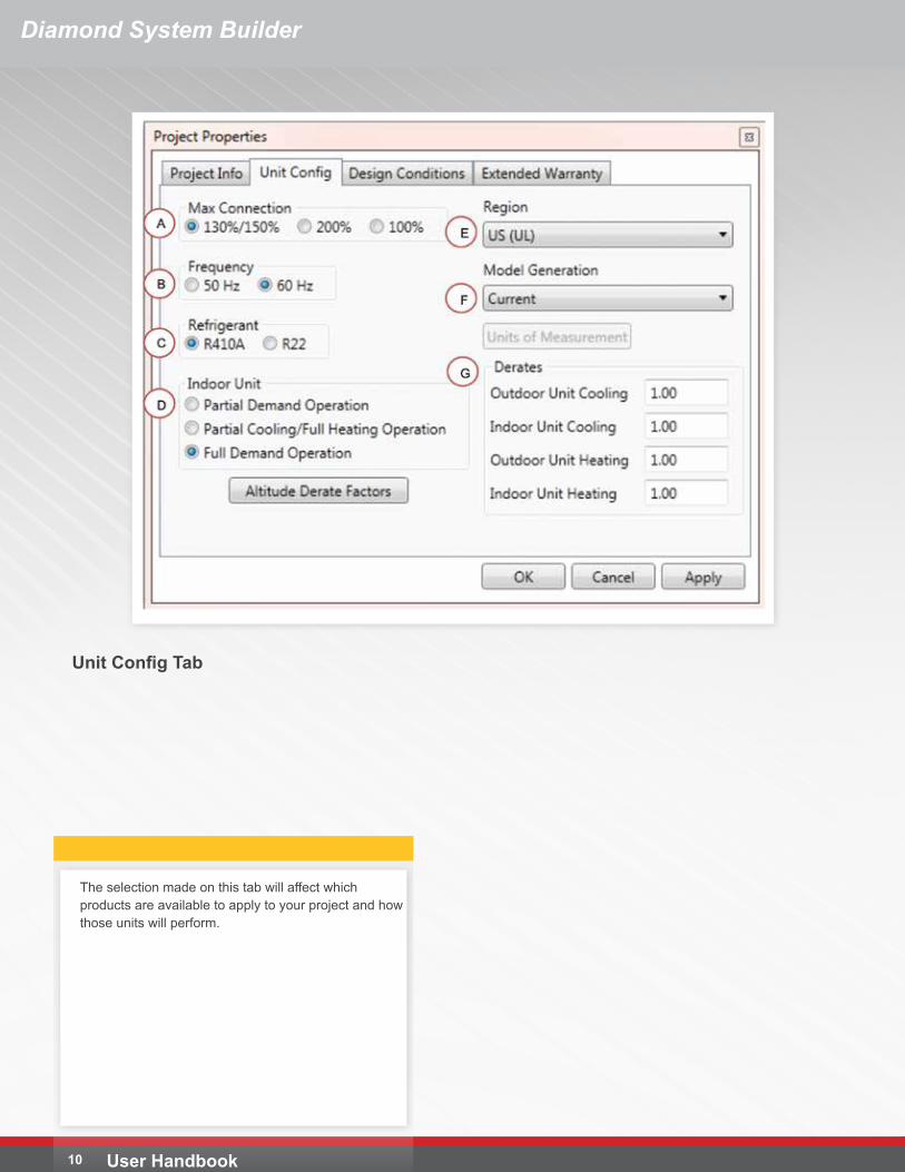
Unit Config Tab
The selection made on this tab will affect which products are available to apply to your project and how those units will perform.
Diamond System Builder
11User Handbook
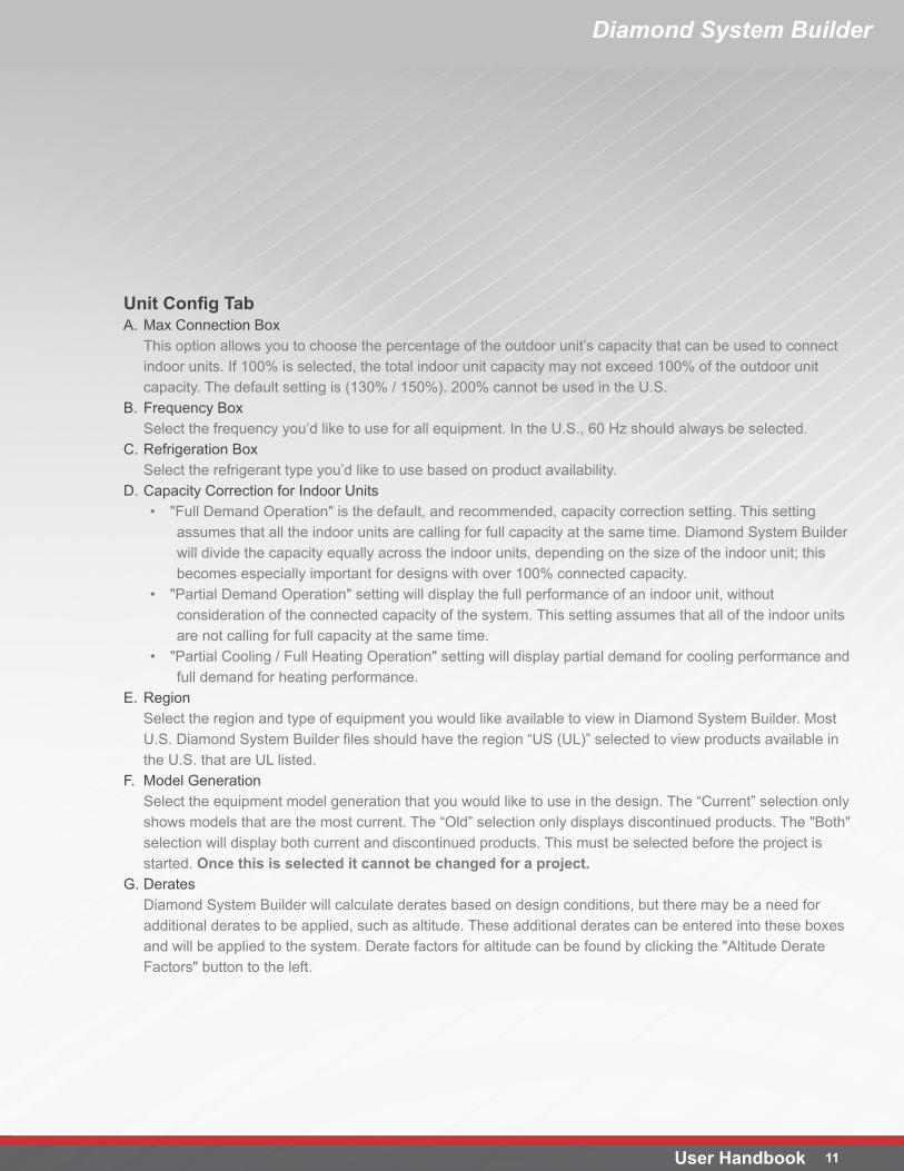
Unit Config TabA. Max Connection Box
This option allows you to choose the percentage of the outdoor unit’s capacity that can be used to connect indoor units. If 100% is selected, the total indoor unit capacity may not exceed 100% of the outdoor unit capacity. The default setting is (130% / 150%). 200% cannot be used in the U.S.
B. Frequency BoxSelect the frequency you’d like to use for all equipment. In the U.S., 60 Hz should always be selected.
C. Refrigeration BoxSelect the refrigerant type you’d like to use based on product availability.
D. Capacity Correction for Indoor Units• "Full Demand Operation" is the default, and recommended, capacity correction setting. This setting
assumes that all the indoor units are calling for full capacity at the same time. Diamond System Builder will divide the capacity equally across the indoor units, depending on the size of the indoor unit; this becomes especially important for designs with over 100% connected capacity.
• "Partial Demand Operation" setting will display the full performance of an indoor unit, without consideration of the connected capacity of the system. This setting assumes that all of the indoor units are not calling for full capacity at the same time.
• "Partial Cooling / Full Heating Operation" setting will display partial demand for cooling performance and full demand for heating performance.
E. RegionSelect the region and type of equipment you would like available to view in Diamond System Builder. Most U.S. Diamond System Builder files should have the region “US (UL)” selected to view products available in the U.S. that are UL listed.
F. Model GenerationSelect the equipment model generation that you would like to use in the design. The “Current” selection only shows models that are the most current. The “Old” selection only displays discontinued products. The "Both" selection will display both current and discontinued products. This must be selected before the project is started. Once this is selected it cannot be changed for a project.
G. DeratesDiamond System Builder will calculate derates based on design conditions, but there may be a need for additional derates to be applied, such as altitude. These additional derates can be entered into these boxes and will be applied to the system. Derate factors for altitude can be found by clicking the "Altitude Derate Factors" button to the left.
Diamond System Builder
User Handbook 12
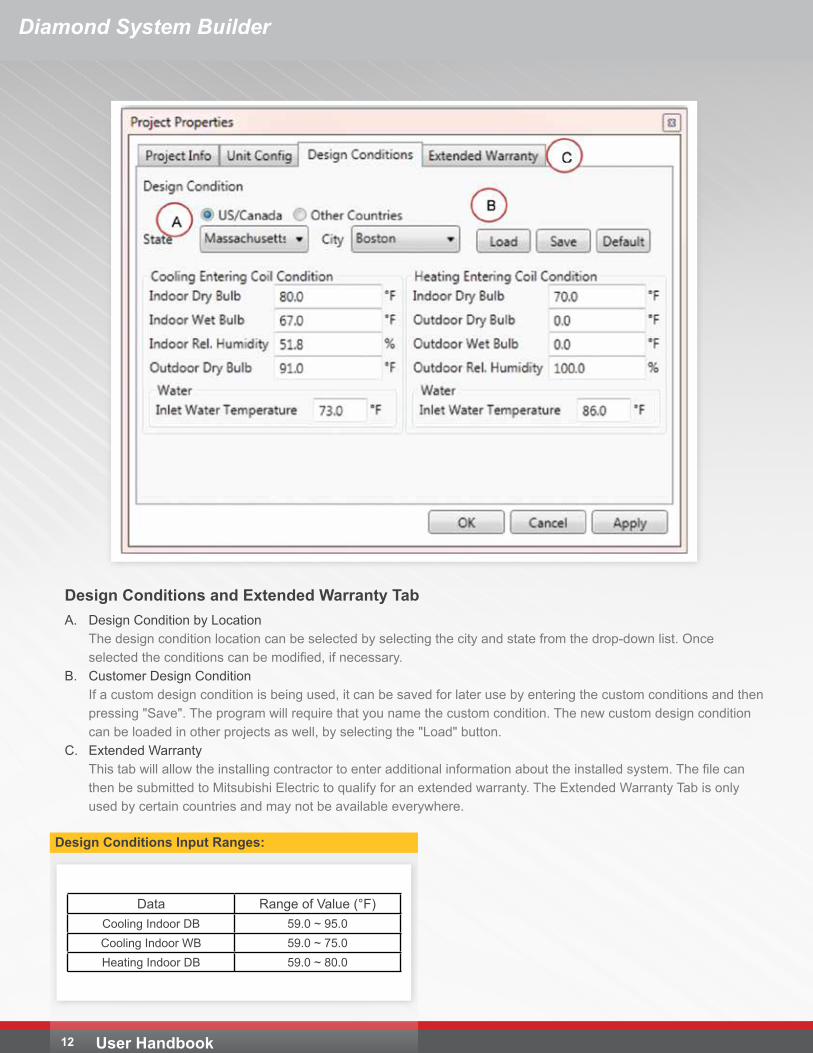
Design Conditions and Extended Warranty TabA. Design Condition by Location
The design condition location can be selected by selecting the city and state from the drop-down list. Once selected the conditions can be modified, if necessary.
B. Customer Design ConditionIf a custom design condition is being used, it can be saved for later use by entering the custom conditions and then pressing "Save". The program will require that you name the custom condition. The new custom design condition can be loaded in other projects as well, by selecting the "Load" button.
C. Extended WarrantyThis tab will allow the installing contractor to enter additional information about the installed system. The file can then be submitted to Mitsubishi Electric to qualify for an extended warranty. The Extended Warranty Tab is only used by certain countries and may not be available everywhere.
Data Range of Value (°F)Cooling Indoor DB 59.0 ~ 95.0Cooling Indoor WB 59.0 ~ 75.0Heating Indoor DB 59.0 ~ 80.0
Design Conditions Input Ranges:
Diamond System Builder
13User Handbook
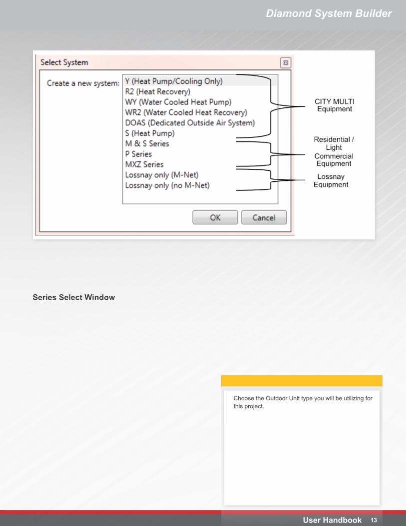
Choose the Outdoor Unit type you will be utilizing for this project.
Series Select Window
User Handbook 14
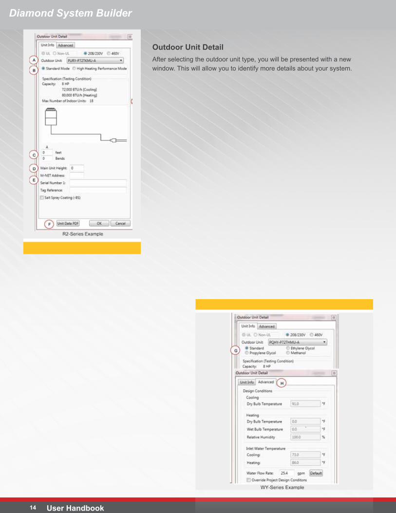
Outdoor Unit DetailAfter selecting the outdoor unit type, you will be presented with a new window. This will allow you to identify more details about your system.
Diamond System Builder
Diamond System Builder
15User Handbook
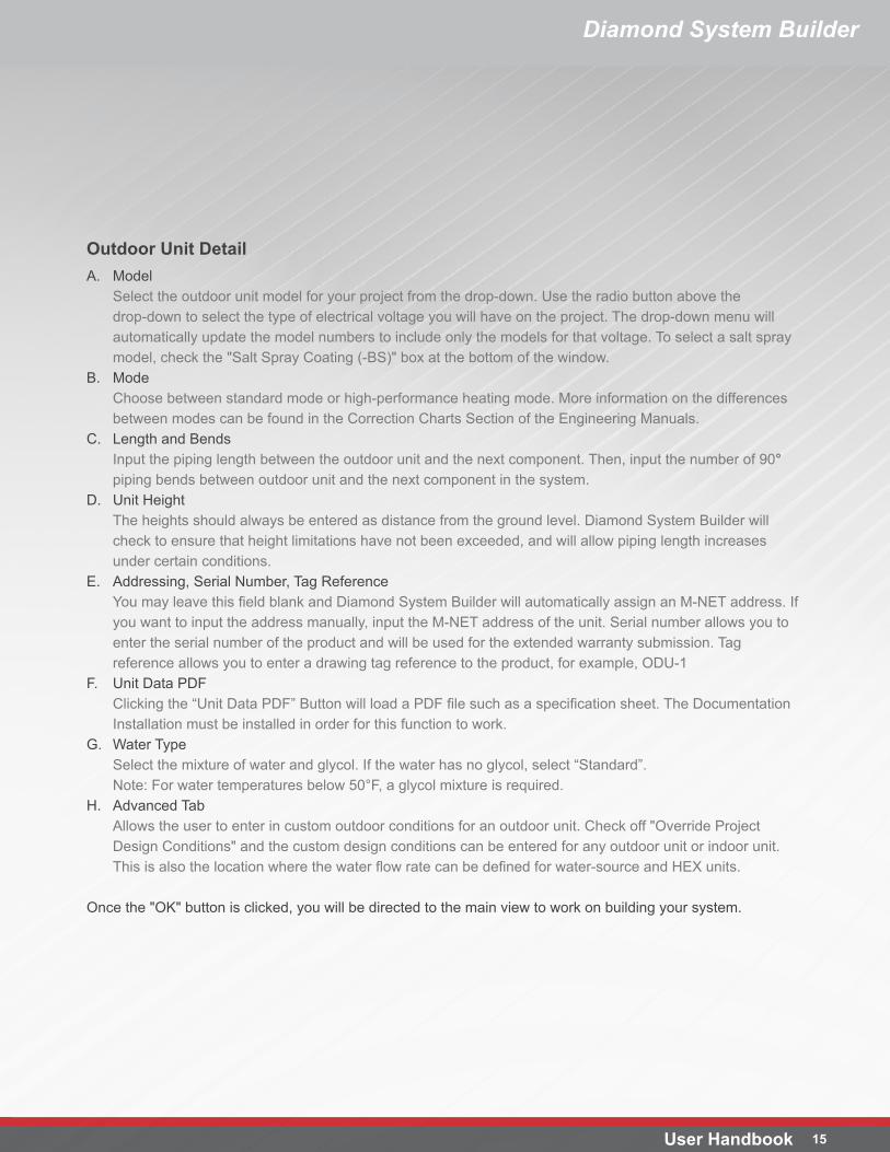
Outdoor Unit DetailA. Model
Select the outdoor unit model for your project from the drop-down. Use the radio button above the drop-down to select the type of electrical voltage you will have on the project. The drop-down menu will automatically update the model numbers to include only the models for that voltage. To select a salt spray model, check the "Salt Spray Coating (-BS)" box at the bottom of the window.
B. ModeChoose between standard mode or high-performance heating mode. More information on the differences between modes can be found in the Correction Charts Section of the Engineering Manuals.
C. Length and BendsInput the piping length between the outdoor unit and the next component. Then, input the number of 90° piping bends between outdoor unit and the next component in the system.
D. Unit HeightThe heights should always be entered as distance from the ground level. Diamond System Builder will check to ensure that height limitations have not been exceeded, and will allow piping length increases under certain conditions.
E. Addressing, Serial Number, Tag ReferenceYou may leave this field blank and Diamond System Builder will automatically assign an M-NET address. If you want to input the address manually, input the M-NET address of the unit. Serial number allows you to enter the serial number of the product and will be used for the extended warranty submission. Tag reference allows you to enter a drawing tag reference to the product, for example, ODU-1
F. Unit Data PDFClicking the “Unit Data PDF” Button will load a PDF file such as a specification sheet. The Documentation Installation must be installed in order for this function to work.
G. Water TypeSelect the mixture of water and glycol. If the water has no glycol, select “Standard”. Note: For water temperatures below 50°F, a glycol mixture is required.
H. Advanced TabAllows the user to enter in custom outdoor conditions for an outdoor unit. Check off "Override Project Design Conditions" and the custom design conditions can be entered for any outdoor unit or indoor unit. This is also the location where the water flow rate can be defined for water-source and HEX units.
Once the "OK" button is clicked, you will be directed to the main view to work on building your system.
Diamond System Builder
User Handbook 16
Entry Screen
Diamond System Builder
17User Handbook
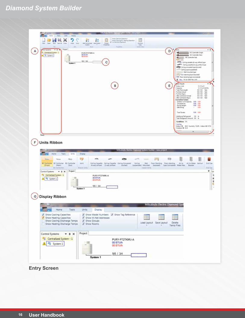
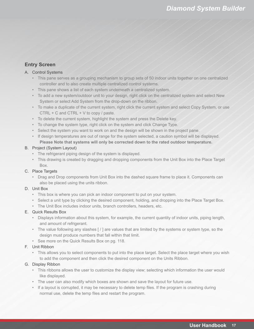
Entry ScreenA. Control Systems
• This pane serves as a grouping mechanism to group sets of 50 indoor units together on one centralized controller and to also create multiple centralized control systems.
• This pane shows a list of each system underneath a centralized system.• To add a new system/outdoor unit to your design, right click on the centralized system and select New
System or select Add System from the drop-down on the ribbon.• To make a duplicate of the current system, right click the current system and select Copy System, or use
CTRL + C and CTRL + V to copy / paste.• To delete the current system, highlight the system and press the Delete key.• To change the system type, right click on the system and click Change Type.• Select the system you want to work on and the design will be shown in the project pane.• If design temperatures are out of range for the system selected, a caution symbol will be displayed.
Please Note that systems will only be corrected down to the rated outdoor temperature.B. Project (System Layout)
• The refrigerant piping design of the system is displayed.• This drawing is created by dragging and dropping components from the Unit Box into the Place Target
Box.C. Place Targets
• Drag and Drop components from Unit Box into the dashed square frame to place it. Components can also be placed using the units ribbon.
D. Unit Box• This box is where you can pick an indoor component to put on your system.• Select a unit type by clicking the desired component, holding, and dropping into the Place Target Box.• The Unit Box includes indoor units, branch controllers, headers, etc.
E. Quick Results Box• Displays information about this system, for example, the current quantity of indoor units, piping length,
and amount of refrigerant.• The value following any slashes [ / ] are values that are limited by the systems or system type, so the
design must produce numbers that fall within that limit.• See more on the Quick Results Box on pg. 118.
F. Unit Ribbon• This allows you to select components to put into the place target. Select the place target where you wish
to add the component and then click the desired component on the Units Ribbon.G. Display Ribbon
• This ribbons allows the user to customize the display view; selecting which information the user would like displayed.
• The user can also modify which boxes are shown and save the layout for future use.• If a layout is corrupted, it may be necessary to delete temp files. If the program is crashing during
normal use, delete the temp files and restart the program.
Diamond System Builder
User Handbook 18
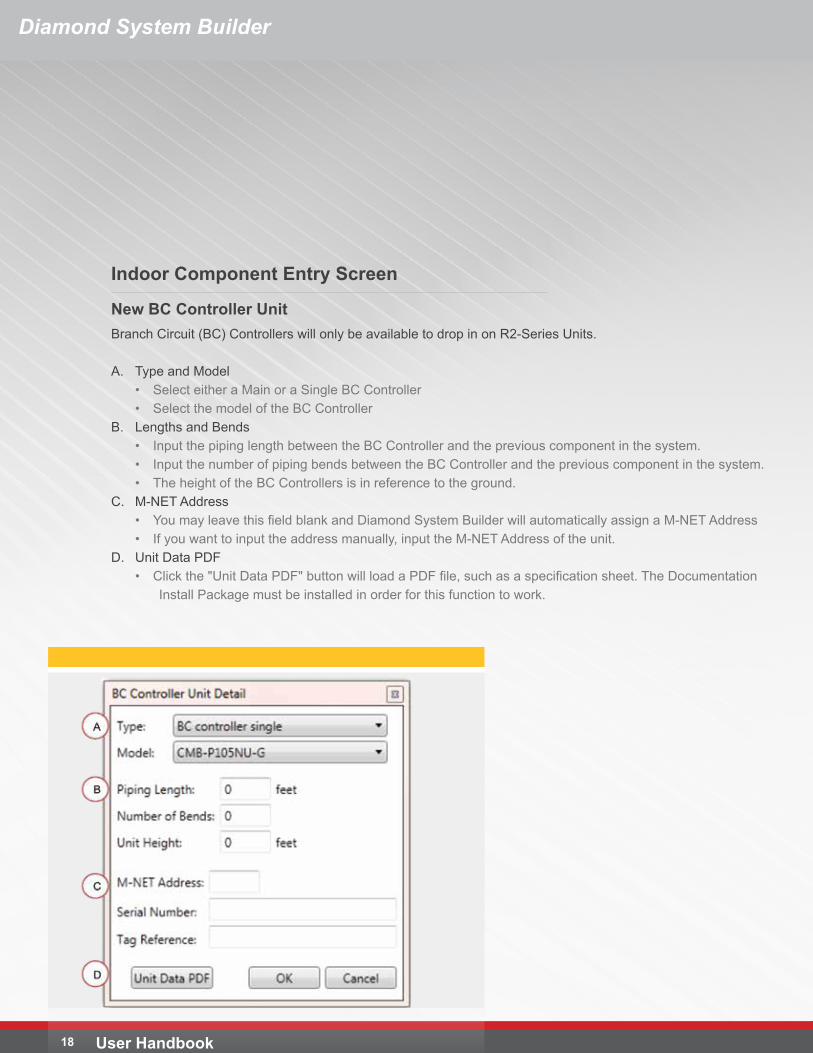
New BC Controller UnitBranch Circuit (BC) Controllers will only be available to drop in on R2-Series Units.
A. Type and Model• Select either a Main or a Single BC Controller• Select the model of the BC Controller
B. Lengths and Bends• Input the piping length between the BC Controller and the previous component in the system.• Input the number of piping bends between the BC Controller and the previous component in the system.• The height of the BC Controllers is in reference to the ground.
C. M-NET Address• You may leave this field blank and Diamond System Builder will automatically assign a M-NET Address• If you want to input the address manually, input the M-NET Address of the unit.
D. Unit Data PDF• Click the "Unit Data PDF" button will load a PDF file, such as a specification sheet. The Documentation
Install Package must be installed in order for this function to work.
Indoor Component Entry Screen
19User Handbook
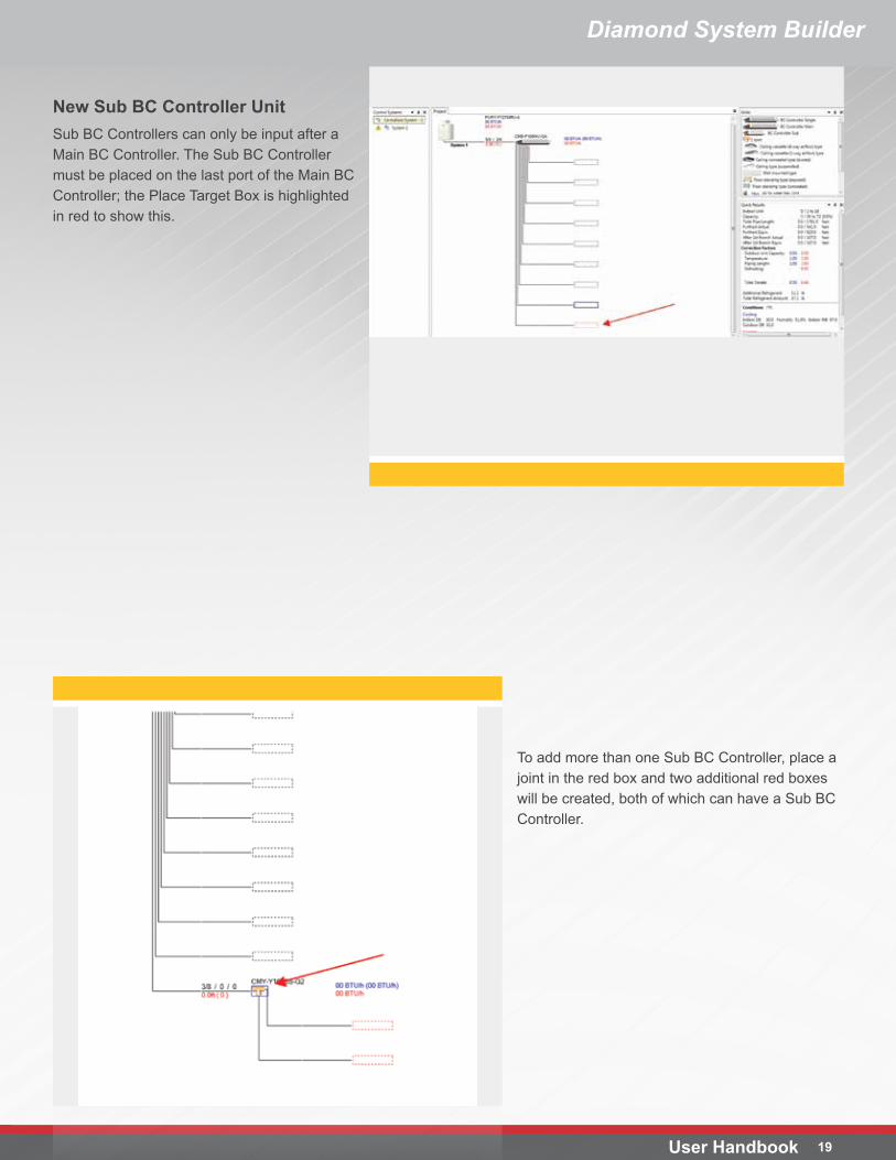
New Sub BC Controller UnitSub BC Controllers can only be input after a Main BC Controller. The Sub BC Controller must be placed on the last port of the Main BC Controller; the Place Target Box is highlighted in red to show this.
To add more than one Sub BC Controller, place a joint in the red box and two additional red boxes will be created, both of which can have a Sub BC Controller.
Diamond System Builder
Diamond System Builder
User Handbook 20
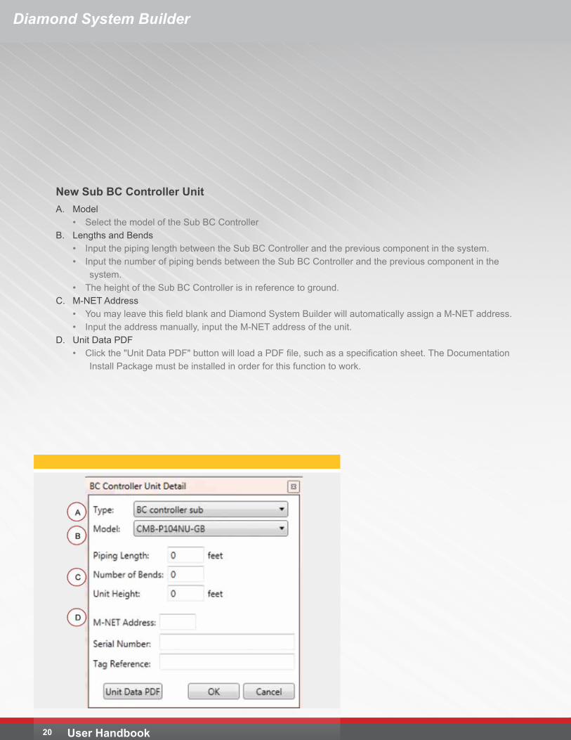
New Sub BC Controller UnitA. Model
• Select the model of the Sub BC ControllerB. Lengths and Bends
• Input the piping length between the Sub BC Controller and the previous component in the system.• Input the number of piping bends between the Sub BC Controller and the previous component in the
system.• The height of the Sub BC Controller is in reference to ground.
C. M-NET Address• You may leave this field blank and Diamond System Builder will automatically assign a M-NET address. • Input the address manually, input the M-NET address of the unit.
D. Unit Data PDF• Click the "Unit Data PDF" button will load a PDF file, such as a specification sheet. The Documentation
Install Package must be installed in order for this function to work.
Diamond System Builder
21User Handbook
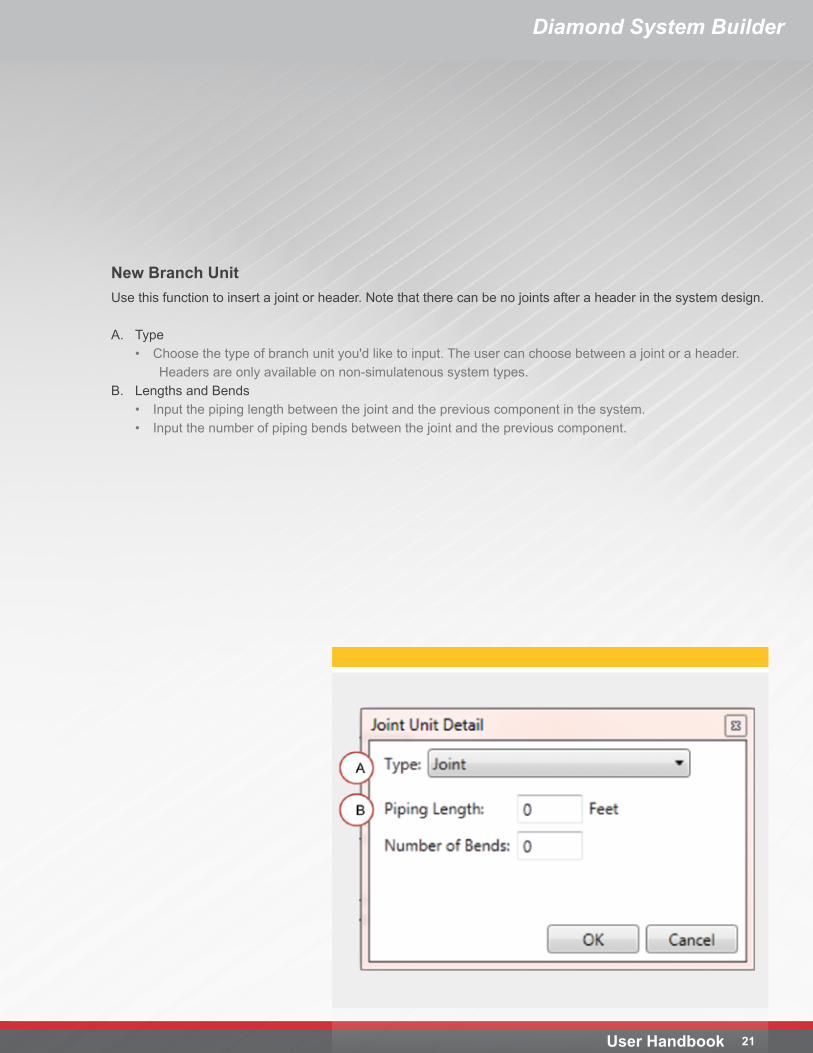
New Branch UnitUse this function to insert a joint or header. Note that there can be no joints after a header in the system design.
A. Type• Choose the type of branch unit you'd like to input. The user can choose between a joint or a header.
Headers are only available on non-simulatenous system types.B. Lengths and Bends
• Input the piping length between the joint and the previous component in the system.• Input the number of piping bends between the joint and the previous component.
Diamond System Builder
User Handbook 22
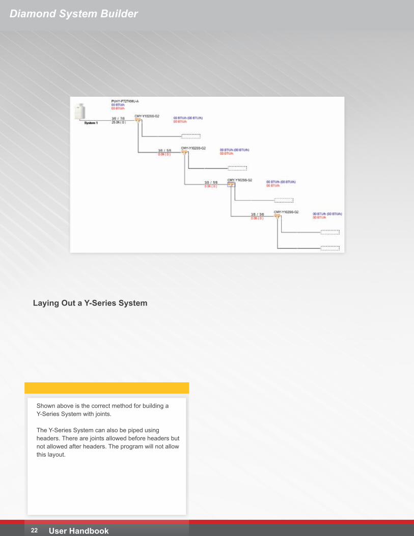
Laying Out a Y-Series System
Shown above is the correct method for building a Y-Series System with joints.
The Y-Series System can also be piped using headers. There are joints allowed before headers but not allowed after headers. The program will not allow this layout.
Diamond System Builder
23User Handbook
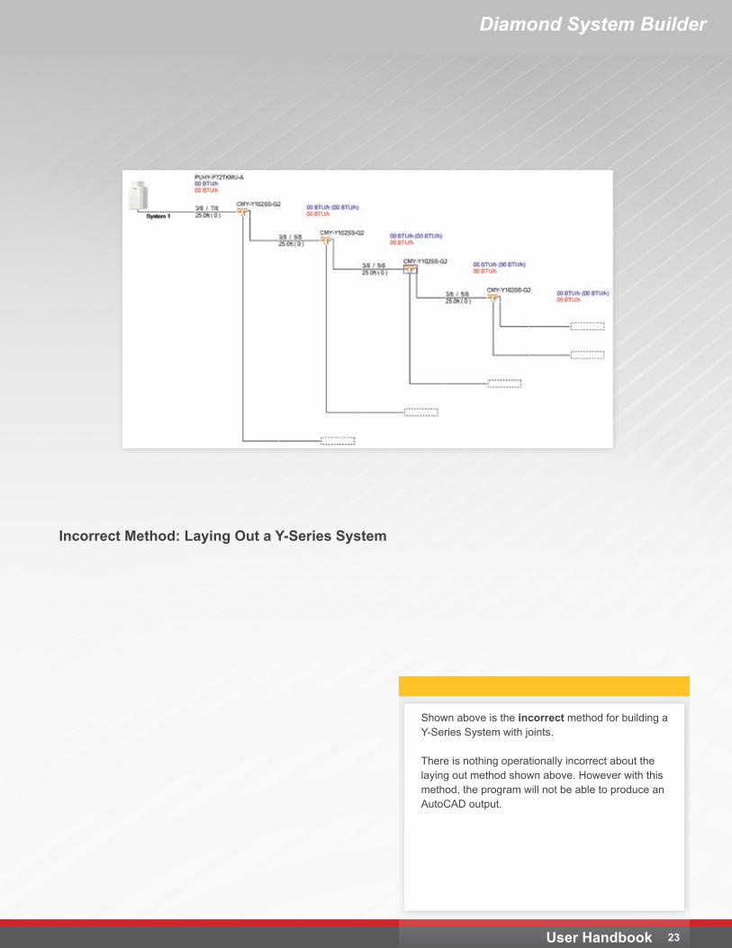
Shown above is the incorrect method for building a Y-Series System with joints.
There is nothing operationally incorrect about the laying out method shown above. However with this method, the program will not be able to produce an AutoCAD output.
Incorrect Method: Laying Out a Y-Series System
Diamond System Builder
User Handbook 24
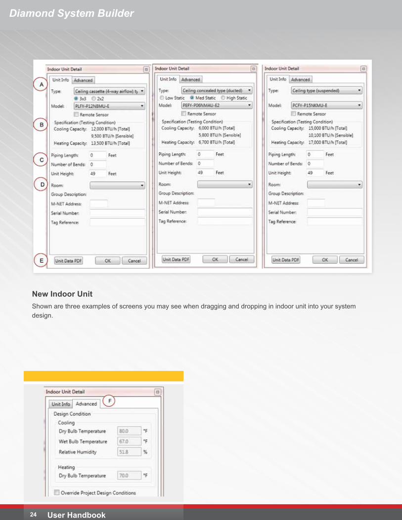
New Indoor UnitShown are three examples of screens you may see when dragging and dropping in indoor unit into your system design.
Diamond System Builder
25User Handbook
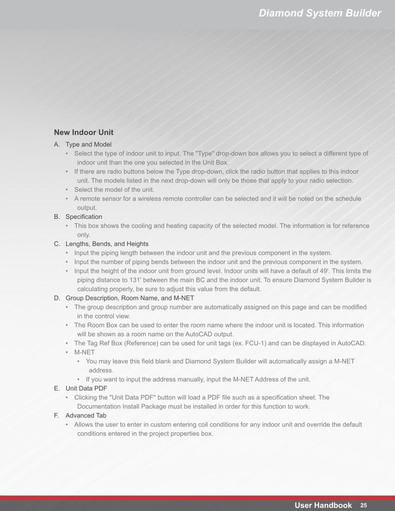
New Indoor UnitA. Type and Model
• Select the type of indoor unit to input. The "Type" drop-down box allows you to select a different type of indoor unit than the one you selected in the Unit Box.
• If there are radio buttons below the Type drop-down, click the radio button that applies to this indoor unit. The models listed in the next drop-down will only be those that apply to your radio selection.
• Select the model of the unit.• A remote sensor for a wireless remote controller can be selected and it will be noted on the schedule
output.B. Specification
• This box shows the cooling and heating capacity of the selected model. The information is for reference only.
C. Lengths, Bends, and Heights• Input the piping length between the indoor unit and the previous component in the system. • Input the number of piping bends between the indoor unit and the previous component in the system.• Input the height of the indoor unit from ground level. Indoor units will have a default of 49'. This limits the
piping distance to 131' between the main BC and the indoor unit. To ensure Diamond System Builder is calculating properly, be sure to adjust this value from the default.
D. Group Description, Room Name, and M-NET• The group description and group number are automatically assigned on this page and can be modified
in the control view.• The Room Box can be used to enter the room name where the indoor unit is located. This information
will be shown as a room name on the AutoCAD output.• The Tag Ref Box (Reference) can be used for unit tags (ex. FCU-1) and can be displayed in AutoCAD.• M-NET
• You may leave this field blank and Diamond System Builder will automatically assign a M-NET address.
• If you want to input the address manually, input the M-NET Address of the unit.E. Unit Data PDF
• Clicking the "Unit Data PDF" button will load a PDF file such as a specification sheet. The Documentation Install Package must be installed in order for this function to work.
F. Advanced Tab• Allows the user to enter in custom entering coil conditions for any indoor unit and override the default
conditions entered in the project properties box.
26 User Handbook
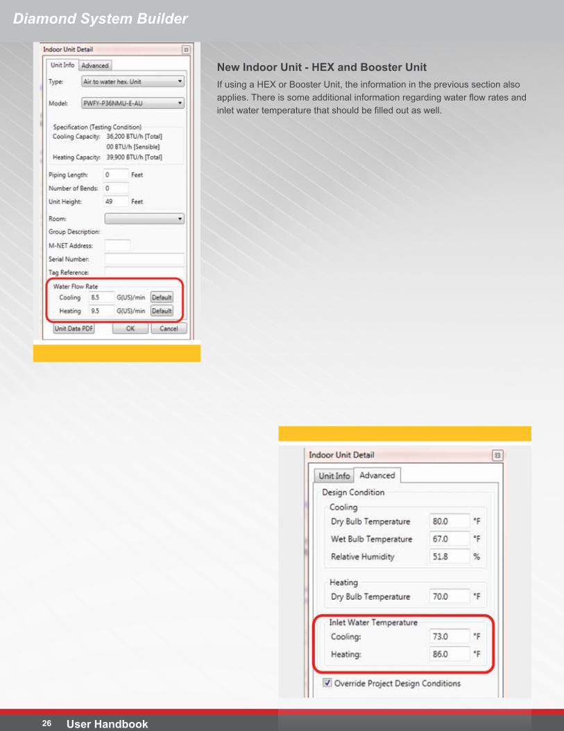
New Indoor Unit - HEX and Booster UnitIf using a HEX or Booster Unit, the information in the previous section also applies. There is some additional information regarding water flow rates and inlet water temperature that should be filled out as well.
Diamond System Builder
27User Handbook
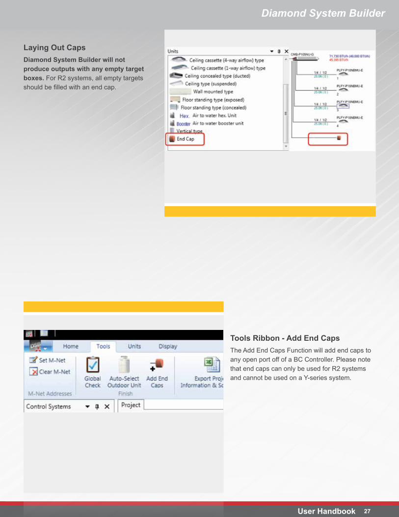
Laying Out CapsDiamond System Builder will not produce outputs with any empty target boxes. For R2 systems, all empty targets should be filled with an end cap.
Tools Ribbon - Add End CapsThe Add End Caps Function will add end caps to any open port off of a BC Controller. Please note that end caps can only be used for R2 systems and cannot be used on a Y-series system.
Diamond System Builder
Diamond System Builder
User Handbook 28
System and Component Design
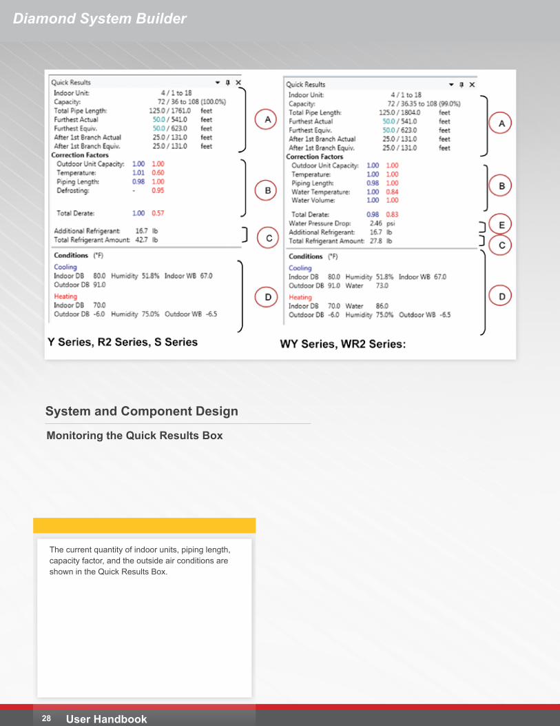
The current quantity of indoor units, piping length, capacity factor, and the outside air conditions are shown in the Quick Results Box.
Monitoring the Quick Results Box
Diamond System Builder
29User Handbook
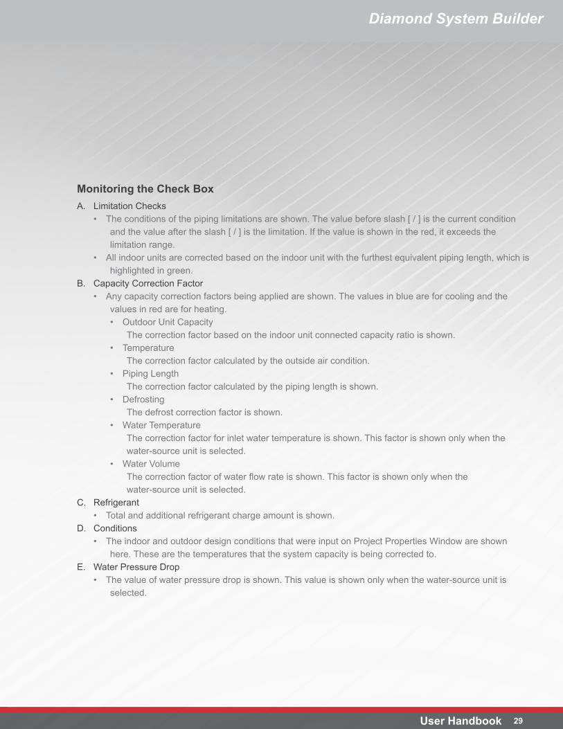
Monitoring the Check BoxA. Limitation Checks
• The conditions of the piping limitations are shown. The value before slash [ / ] is the current condition and the value after the slash [ / ] is the limitation. If the value is shown in the red, it exceeds the limitation range.
• All indoor units are corrected based on the indoor unit with the furthest equivalent piping length, which is highlighted in green.
B. Capacity Correction Factor• Any capacity correction factors being applied are shown. The values in blue are for cooling and the
values in red are for heating.• Outdoor Unit Capacity
The correction factor based on the indoor unit connected capacity ratio is shown.• Temperature
The correction factor calculated by the outside air condition.• Piping Length
The correction factor calculated by the piping length is shown.• Defrosting
The defrost correction factor is shown.• Water Temperature
The correction factor for inlet water temperature is shown. This factor is shown only when the water-source unit is selected.
• Water VolumeThe correction factor of water flow rate is shown. This factor is shown only when the water-source unit is selected.
C. Refrigerant• Total and additional refrigerant charge amount is shown.
D. Conditions• The indoor and outdoor design conditions that were input on Project Properties Window are shown
here. These are the temperatures that the system capacity is being corrected to.E. Water Pressure Drop
• The value of water pressure drop is shown. This value is shown only when the water-source unit is selected.
Diamond System Builder
User Handbook 30
Controls Design
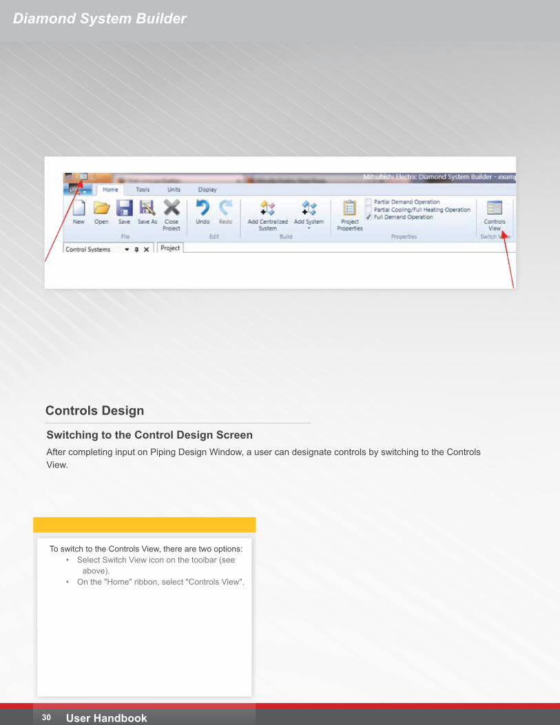
To switch to the Controls View, there are two options:• Select Switch View icon on the toolbar (see
above).• On the "Home" ribbon, select "Controls View".
Switching to the Control Design ScreenAfter completing input on Piping Design Window, a user can designate controls by switching to the Controls View.
Diamond System Builder
31User Handbook
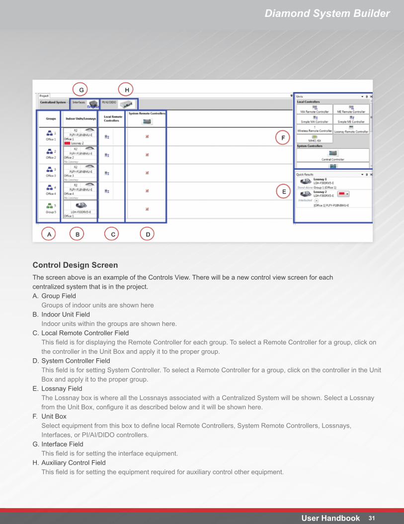
Control Design ScreenThe screen above is an example of the Controls View. There will be a new control view screen for each centralized system that is in the project.A. Group Field
Groups of indoor units are shown hereB. Indoor Unit Field
Indoor units within the groups are shown here.C. Local Remote Controller Field
This field is for displaying the Remote Controller for each group. To select a Remote Controller for a group, click on the controller in the Unit Box and apply it to the proper group.
D. System Controller FieldThis field is for setting System Controller. To select a Remote Controller for a group, click on the controller in the Unit Box and apply it to the proper group.
E. Lossnay FieldThe Lossnay box is where all the Lossnays associated with a Centralized System will be shown. Select a Lossnay from the Unit Box, configure it as described below and it will be shown here.
F. Unit BoxSelect equipment from this box to define local Remote Controllers, System Remote Controllers, Lossnays, Interfaces, or PI/AI/DIDO controllers.
G. Interface FieldThis field is for setting the interface equipment.
H. Auxiliary Control FieldThis field is for setting the equipment required for auxiliary control other equipment.
User Handbook 32
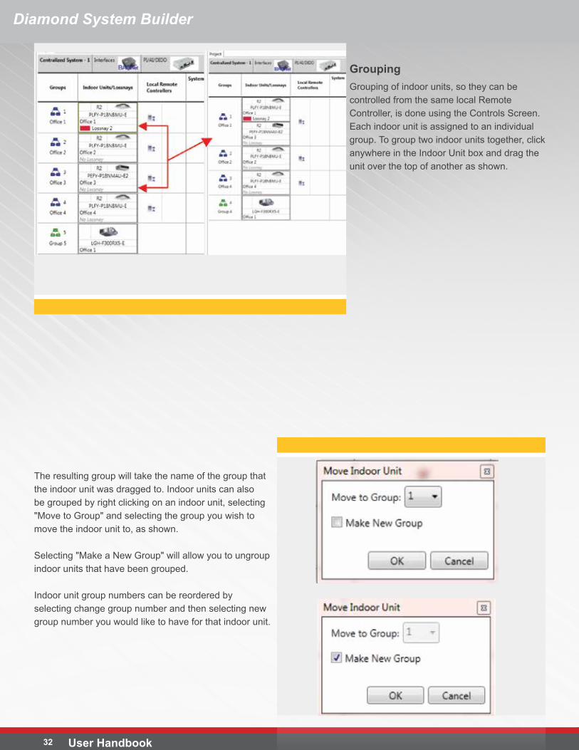
The resulting group will take the name of the group that the indoor unit was dragged to. Indoor units can also be grouped by right clicking on an indoor unit, selecting "Move to Group" and selecting the group you wish to move the indoor unit to, as shown.
Selecting "Make a New Group" will allow you to ungroup indoor units that have been grouped.
Indoor unit group numbers can be reordered by selecting change group number and then selecting new group number you would like to have for that indoor unit.
GroupingGrouping of indoor units, so they can be controlled from the same local Remote Controller, is done using the Controls Screen. Each indoor unit is assigned to an individual group. To group two indoor units together, click anywhere in the Indoor Unit box and drag the unit over the top of another as shown.
Diamond System Builder
Diamond System Builder
33User Handbook
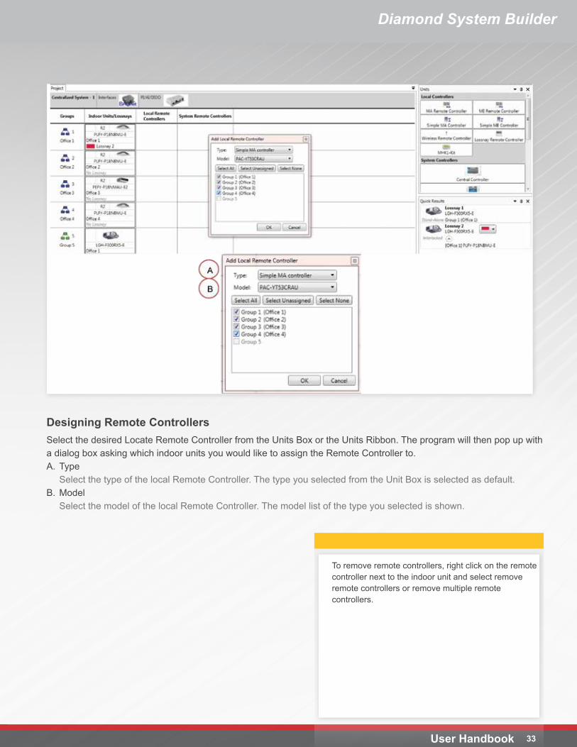
Designing Remote ControllersSelect the desired Locate Remote Controller from the Units Box or the Units Ribbon. The program will then pop up with a dialog box asking which indoor units you would like to assign the Remote Controller to. A. Type
Select the type of the local Remote Controller. The type you selected from the Unit Box is selected as default.B. Model
Select the model of the local Remote Controller. The model list of the type you selected is shown.
To remove remote controllers, right click on the remote controller next to the indoor unit and select remove remote controllers or remove multiple remote controllers.
Diamond System Builder
User Handbook 34
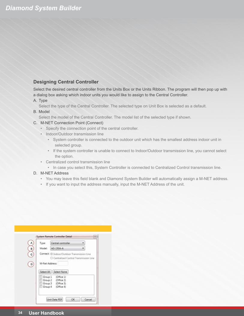
Designing Central ControllerSelect the desired central controller from the Units Box or the Units Ribbon. The program will then pop up with a dialog box asking which indoor units you would like to assign to the Central Controller. A. Type
Select the type of the Central Controller. The selected type on Unit Box is selected as a default.B. Model
Select the model of the Central Controller. The model list of the selected type if shown.C. M-NET Connection Point (Connect)
• Specify the connection point of the central controller.• Indoor/Outdoor transmission line
• System controller is connected to the outdoor unit which has the smallest address indoor unit in selected group.
• If the system controller is unable to connect to Indoor/Outdoor transmission line, you cannot select the option.
• Centralized control transmission line• In case you select this, System Controller is connected to Centralized Control transmission line.
D. M-NET Address• You may leave this field blank and Diamond System Builder will automatically assign a M-NET address. • If you want to input the address manually, input the M-NET Address of the unit.
Diamond System Builder
35User Handbook
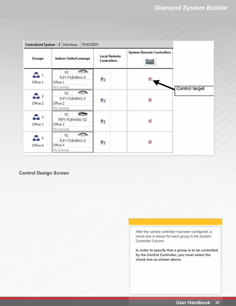
After the central controller has been configured, a check box is shown for each group in the System Controller Column.
In order to specify that a group is to be controlled by the Central Controller, you must select the check box as shown above.
Control Design Screen
36 User Handbook
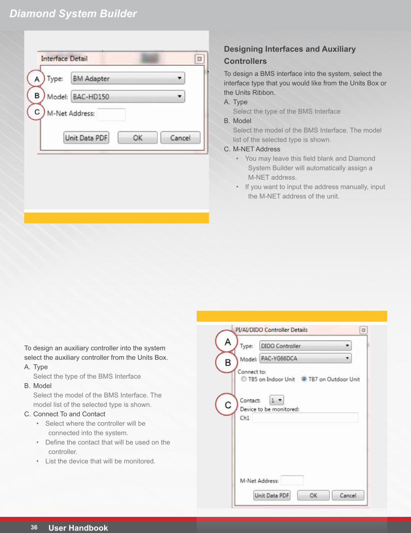
To design an auxiliary controller into the system select the auxiliary controller from the Units Box.A. Type
Select the type of the BMS InterfaceB. Model
Select the model of the BMS Interface. The model list of the selected type is shown.
C. Connect To and Contact• Select where the controller will be
connected into the system.• Define the contact that will be used on the
controller.• List the device that will be monitored.
Designing Interfaces and Auxiliary ControllersTo design a BMS interface into the system, select the interface type that you would like from the Units Box or the Units Ribbon.A. Type
Select the type of the BMS InterfaceB. Model
Select the model of the BMS Interface. The model list of the selected type is shown.
C. M-NET Address• You may leave this field blank and Diamond
System Builder will automatically assign a M-NET address.
• If you want to input the address manually, input the M-NET address of the unit.
Diamond System Builder
37User Handbook
Diamond System Builder
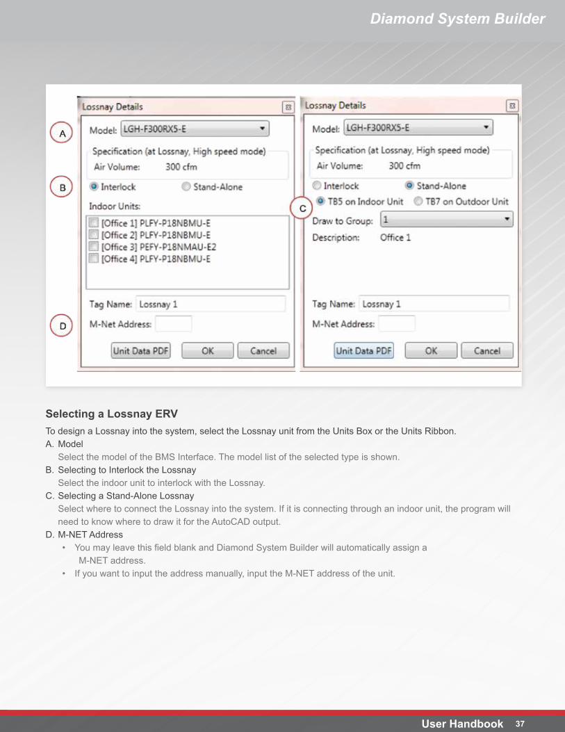
Selecting a Lossnay ERVTo design a Lossnay into the system, select the Lossnay unit from the Units Box or the Units Ribbon.A. Model
Select the model of the BMS Interface. The model list of the selected type is shown.B. Selecting to Interlock the Lossnay
Select the indoor unit to interlock with the Lossnay.C. Selecting a Stand-Alone Lossnay
Select where to connect the Lossnay into the system. If it is connecting through an indoor unit, the program will need to know where to draw it for the AutoCAD output.
D. M-NET Address• You may leave this field blank and Diamond System Builder will automatically assign a
M-NET address.• If you want to input the address manually, input the M-NET address of the unit.
Diamond System Builder
User Handbook 38
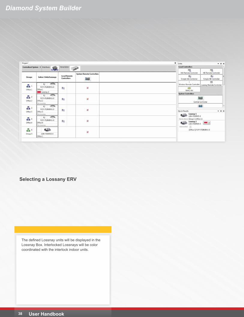
Selecting a Lossany ERV
The defined Lossnay units will be displayed in the Lossnay Box. Interlocked Lossnays will be color coordinated with the interlock indoor units.
39User Handbook
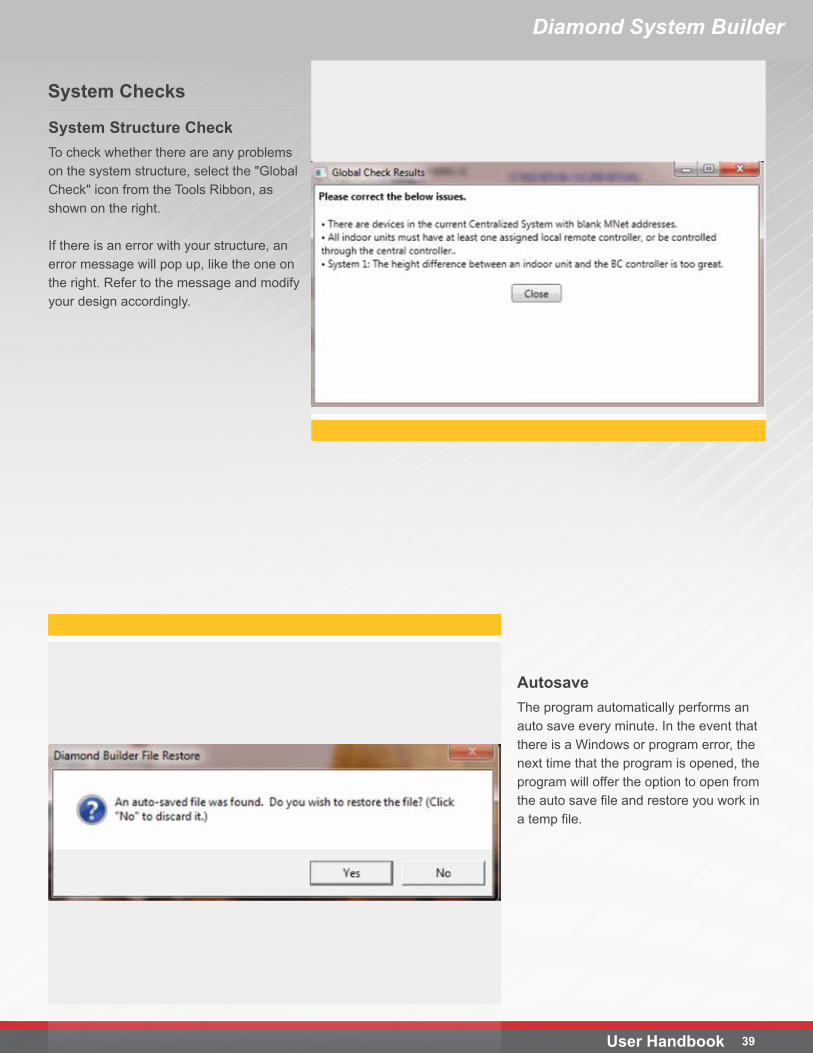
System Structure CheckTo check whether there are any problems on the system structure, select the "Global Check" icon from the Tools Ribbon, as shown on the right.
If there is an error with your structure, an error message will pop up, like the one on the right. Refer to the message and modify your design accordingly.
System Checks
AutosaveThe program automatically performs an auto save every minute. In the event that there is a Windows or program error, the next time that the program is opened, the program will offer the option to open from the auto save file and restore you work in a temp file.
Diamond System Builder
40
Diamond System Builder
User Handbook
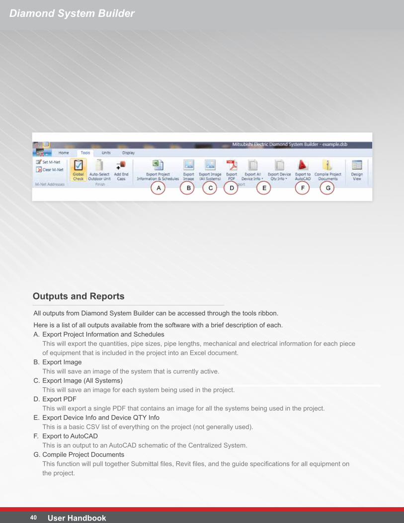
All outputs from Diamond System Builder can be accessed through the tools ribbon.
Here is a list of all outputs available from the software with a brief description of each.A. Export Project Information and Schedules
This will export the quantities, pipe sizes, pipe lengths, mechanical and electrical information for each piece of equipment that is included in the project into an Excel document.
B. Export ImageThis will save an image of the system that is currently active.
C. Export Image (All Systems)This will save an image for each system being used in the project.
D. Export PDFThis will export a single PDF that contains an image for all the systems being used in the project.
E. Export Device Info and Device QTY InfoThis is a basic CSV list of everything on the project (not generally used).
F. Export to AutoCADThis is an output to an AutoCAD schematic of the Centralized System.
G. Compile Project DocumentsThis function will pull together Submittal files, Revit files, and the guide specifications for all equipment on the project.
Outputs and Reports
41User Handbook
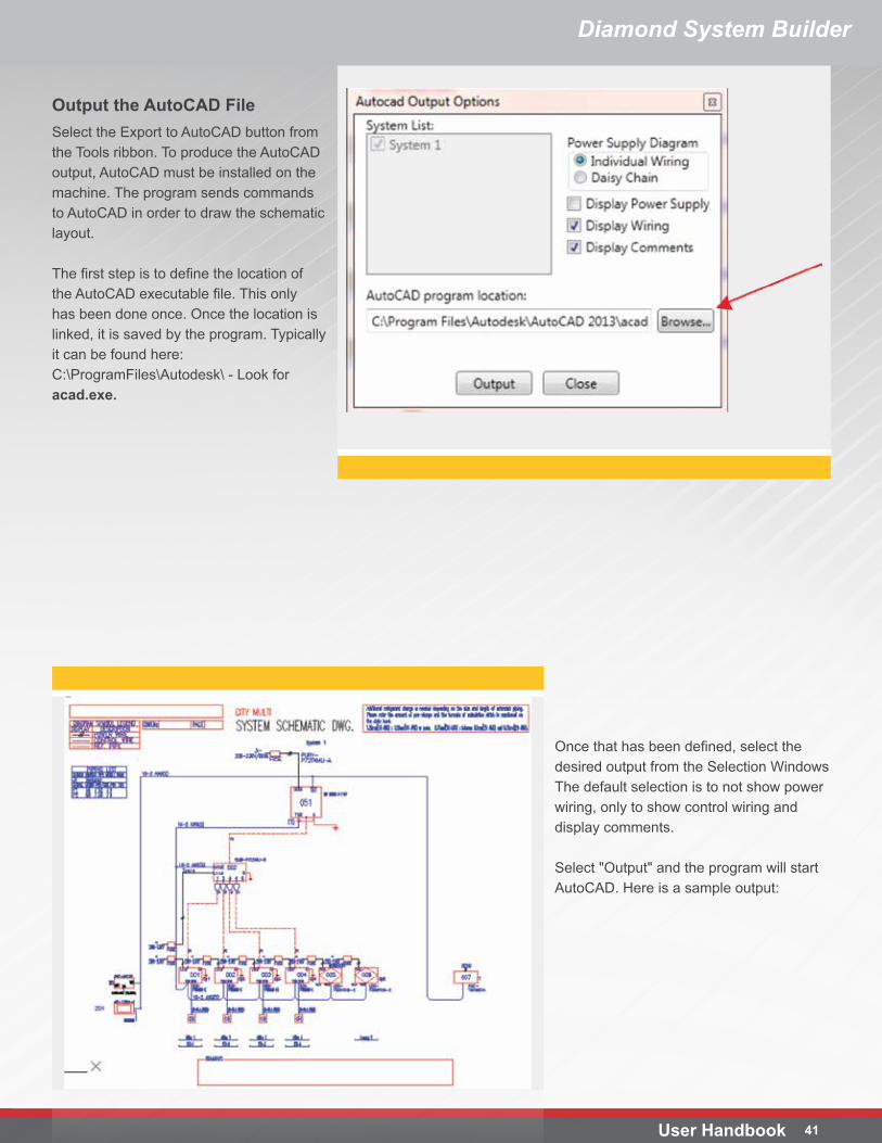
Output the AutoCAD FileSelect the Export to AutoCAD button from the Tools ribbon. To produce the AutoCAD output, AutoCAD must be installed on the machine. The program sends commands to AutoCAD in order to draw the schematic layout.
The first step is to define the location of the AutoCAD executable file. This only has been done once. Once the location is linked, it is saved by the program. Typically it can be found here: C:\ProgramFiles\Autodesk\ - Look for acad.exe.
Once that has been defined, select the desired output from the Selection Windows The default selection is to not show power wiring, only to show control wiring and display comments.
Select "Output" and the program will start AutoCAD. Here is a sample output:
Diamond System Builder
Diamond System Builder
User Handbook 42
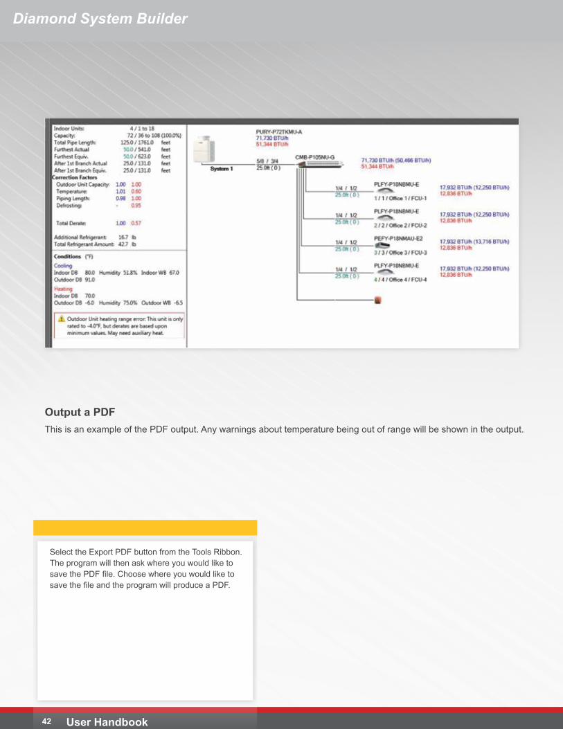
Output a PDFThis is an example of the PDF output. Any warnings about temperature being out of range will be shown in the output.
Select the Export PDF button from the Tools Ribbon. The program will then ask where you would like to save the PDF file. Choose where you would like to save the file and the program will produce a PDF.
43User Handbook
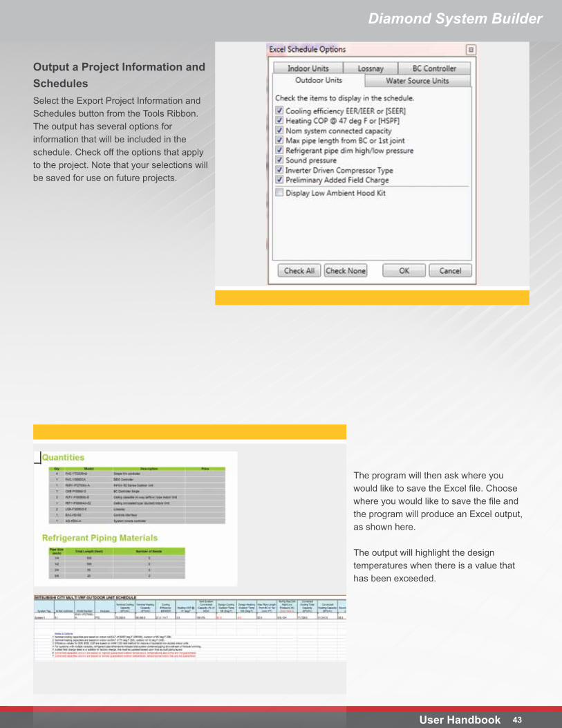
Output a Project Information and SchedulesSelect the Export Project Information and Schedules button from the Tools Ribbon. The output has several options for information that will be included in the schedule. Check off the options that apply to the project. Note that your selections will be saved for use on future projects.
The program will then ask where you would like to save the Excel file. Choose where you would like to save the file and the program will produce an Excel output, as shown here.
The output will highlight the design temperatures when there is a value that has been exceeded.
Diamond System Builder

DSB Handbook - 02_13