Embed Size (px)
Citation preview
May 2011
www.augi.com www.augiworld.com
AutodeskInventorAutodeskFactoryDesign SuiteImplementation and Integration
Diamond Sponsor
Also in this issue...
• AutoCAD 2012 Implementation: Consider This
• BUILT - BIM to FM
• Revit Structure 2012 -Assembly and Part Commands
2 www.augi.com May2011
AUGIWorld
contents product focus
May
201
1
4 EDITOR’S NOTE5 AUTOCAD MAP 2012 - FIRST
IMPRESSIONS8 AUTOCAD 2012 - IMPLEMENTATION:
CONSIDER THIS12 AUTOCAD ARCHITECTURE 2011/2012
PROJECT NAVIGATOR: THE ULTIMATE ORGANIZER
17 AUTOCAD CIVIL 3D 2012 AND MORE - 1...2... CIVIL 3D IMPLEMENT
21 BUILT - BIM TO FM24 REVIT ARCHITECTURE 2012 - BIG
QUESTIONS28 AUTODESK REVIT - THE INTERIOR
SIDE OF REVIT
36 AUTODESK INVENTOR - AUTODESK FACTORY DESIGN SUITE IMPLEMENTATION AND INTEGRATION
42 AUTODESK NAVISWORKS - IMPLEMENTATION CONCEPT AND PROCESS
48 REVIT MEP - SETTING UP FILTERS IN REVIT MEP
52 REVIT STRUCTURE 2012 - ASSEMBLY AND PART COMMANDS
56 AUTODESK 3DS MAX DESIGN - SCANLINE RENDERER: SIMULATING GLOBAL ILLUMINATION IN 3DS MAX
62 AUTOCAD MEP - AUTOCAD MEP IMPLEMENTATION - PART ONE
departments51 INSIDE TRACK
AUGIWorld brings you recentdevelopments in Autodesk and related3rd party software industries
59 HEADS UPUpdates, Service Packs and TopKnown Issues
68 AUTODESK INSIDER15 Questions with Volker Joseph
Autodesk, AutoCAD, Autodesk Architectural Desktop, Autodesk Revit, Autodesk Building Systems, Autodesk Civil Design, Autodesk Inventor and DWF are either registered trademarks or trademarks of Autodesk, Inc. in the U.S.A. and/or in certain other countries. All other brand names, product names, or trademarks belong to their respective holders.
8 17
28 52
May20114 www.augi.com
Editor’sNote
4 www.augi.com April2011
Editor’sNote
welcome to the annual review of the latest Autodesk pres-ents, er, products! As I sit and write this I am on a plane returning home from attending one of the Autodesk
industry Media Day events. This was a chance for those in the media, like magazine publishing, to get a sneak peek at what Au-
todesk is bringing to market this year. Some details have been leaked or released already and this issue hopes to unveil a good deal of the rest for you.
Our authors are daily users of the products they write about. In most cases, they have been playing with the software during the last several months of development. Of course, nothing beats getting your own fingers on the soft-ware. Depending on your budget and situation, some of you have already started getting software delivered and the rest will be out shortly. If you can’t upgrade at this time, most, if not all, products have trial software you can download and try out. Check out www.autodesk.com for that.
Over at AUGIWorld we have been tweaking our Editorial Calendar, which you can find via the hyperlink. In a publication such as this, an Editorial Calendar is somewhat like the flavoring of a given issue. Most articles will follow the issue theme, but there will always be something spicy that falls outside of the preset plan and adds some kick to the issue. I want to en-courage you budding writers to contact me or any of the Content Managers to have a go at writing. I should add that you can be published via AUGI HotNews just as easily. Contact Marilyn Law for more info on the monthly AUGI HotNews newsletter.
This issue also continues the growth of our Content Manager team, which will be bringing you rich and interesting articles in the magazine through-out the year. Newly installed as Content Managers are Andra Marquardt,Darren Young, David Mills, James Salmon, Lonnie Cumpton, Phil Russo and Todd Shackelford. We still have a few vacancies to fill. Perhaps you are interested in helping find articles to publish?
With that I wish you more disk space and happy installs! Thanks for reading!
David Harrington
➲
AUGIWorldwww.augiworld. comEditors Editor-in-Chief david Harrington - [email protected]
Copy Editor Marilyn law - [email protected]
Layout Editor tim varnau - [email protected]
Content Managers autocad - Brian Bentonautocad architecture - Melinda Heavrinautocad civil 3d - christopher fugittautocad Map - andra Marquardt autocad Mep - Beth powellautodesk insider - david Millscolumn: Built - James salmoncolumn: Heads up - william troeak column: inside track - erik lewisinventor - John evansnavisworks - darren youngrevit architecture - lonnie cumptonrevit Mep - todd shackelfordrevit structure - phil russo
Advertising / Reprint Sales david Harrington - [email protected]
AUGI Board of DirectorsPresidentdavid Harrington
Senior Vice President Bill adams
Vice President peter Jamtgaard
Treasurer paul kirill
Secretary Melanie perry
Directorsr. robert Bellshaun Bryantdonnie gladfelterMatt worlandscott wilcox
Published by: AUGIWorld is published by autodesk user group international, inc. augi makes no war-ranty for the use of its products and assumes no responsibility for any errors which may appear in this publication nor does it make a commitment to update the information con-tained herein. AUGIWorld is copyright ©2011 augi. no information in this magazine may be reproduced without expressed written permis-sion from augi.
all registered trademarks and trademarks included in this magazine are held by their re-spective companies. every attempt was made to include all trademarks and registered trade-marks where indicated by their companies.
AUGIWorldwww.augiworld. com
EditorsEditor-in-ChiefDavid Harrington - [email protected]
Copy EditorMarilyn Law - [email protected]
Layout EditorDebby Gwaltney - [email protected]
Content ManagersAutoCAD - Brian BentonAutoCAD Architecture - Melinda HeavrinAutoCAD Civil 3D - Christopher FugittAutoCAD MAP - Andra MarquardtAutoCAD MEP - Beth PowellAutodesk Insider - David MillsColumn: Built - James SalmonColumn: Heads Up - William TroeakColumn: Inside Track - Erik LewisInventor - John EvansNavisworks - Darren YoungRevit Architecture - Lonnie CumptonRevit MEP - Todd ShackelfordRevit Structure - Phil Russo
Advertising/Reprint SalesDavid Harrington • [email protected]
AUGI Board of DirectorsPresidentDavid Harrington
Senior Vice PresidentBill Adams
Vice PresidentPeter Jamtgaard
TreasurerPaul Kirill
SecretaryMelanie Perry
DirectorsR. Robert BellShaun BryantDonnie GladfelterMatt WorlandScott Wilcox
Published by:AUGIWorld is published by Autodesk User Group International, Inc. AUGI makes no war-ranty for the use of its products and assumes no responsibility for any errors which may appear in this publication nor does it make a commitment to update the information contained herein. AUGIWorld is Copyright ©2011 AUGI. No information in this magazine may be reproduced without expressed written permission from AUGI.All registered trademarks and trademarks included in this magazine are held by their re-spective companies. Every attempt was made to include all trademarks and registered trade-marks where indicated by their companies.
Hello readers! This exciting (and plump) issue of AUGIWorld is all about implementing, or implementation, of your brand new Au-todesk software! We have a large and varied collection of articles
based on the implementation theme, and we’ve included other articles about Autodesk software and industry technologies. Our merger of AUGIWorld and AUGI | AEC Edge and the increased frequency of the magazine is
proving to be a great way to service the industry and put interesting material in your hands every month!
So what else is new in this issue? Plenty!
James Salmon rolls out a new column called BUILT, covering BIM to FM. This is interest-ing because there are a lot of issues in the A/E/C industry that are not software related.
Erik Lewis highlights in “Inside Track” a number of new products hitting the market that you should be aware of. But you can help as well! If you hear about something new, cool, and interesting, email him at [email protected].
William Troeak dives deep and pulls up some gold in the form of patches and updates! Just because Autodesk rolls out 2012 doesn’t mean that releases 2011 and earlier are frozen in place. Using an “older” version? Check out the “Heads Up” for your products.
And this month our Autodesk Insider is Volker Joseph. This is a real treat for me as I’m also collaborating with Volker on the new AUGI Wish List system that is in development. Look for that later!
Now I have mentioned the AUGI Library before, but it is really turning into a cool thing. We are loading it up with articles from AUGI HotNews newsletter. The Library is also going to be home of articles from this fine publication. But what if you want to contribute, but not necessarily be published in HotNews or AUGIWorld? You still can! We don’t have the submission forms built yet, but you can contribute articles by emailing them in DOC form to [email protected]. Be sure to have all figures captioned and don’t forget your bio and picture!
With that I hope you let your fingers do your talking and you get authoring! Thanks for reading!
➲
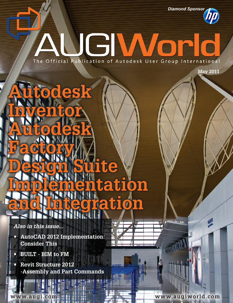
Cover Image: Shanghai Pudong International Airport Terminal 2, Shang-hai, China. Photo Copyright © 2008 - Shaan Hurley. Reuse of full or partial copyright image, in any form, without prior written permission is strictly prohibited. Visit Shaan’s blog at http://autodesk.blogs.com.
May2011 www.augiworld.com5
prod
uct focu
sAutoCADMAP
One thing that has always impressed me about Autodesk is that it listens well to its custom-ers. It seems that whenever I have an issue
with one version of AutoCAD, it’s resolved by the time the next version is released. Version 2012 of AutoCAD® Map is no exception. There are quite a few
enhancements that I’m excited about. I’ll discuss five in this article.
REVISED WORKSPACES
When you first load AutoCAD Map, you will immediately notice there are no Tool-based and Task-based Geospatial Workspaces. These have been replaced with Planning and Analysis and Maintenance Workspac-es. 2D Drafting and Map Classic are still available (see Figure 1).
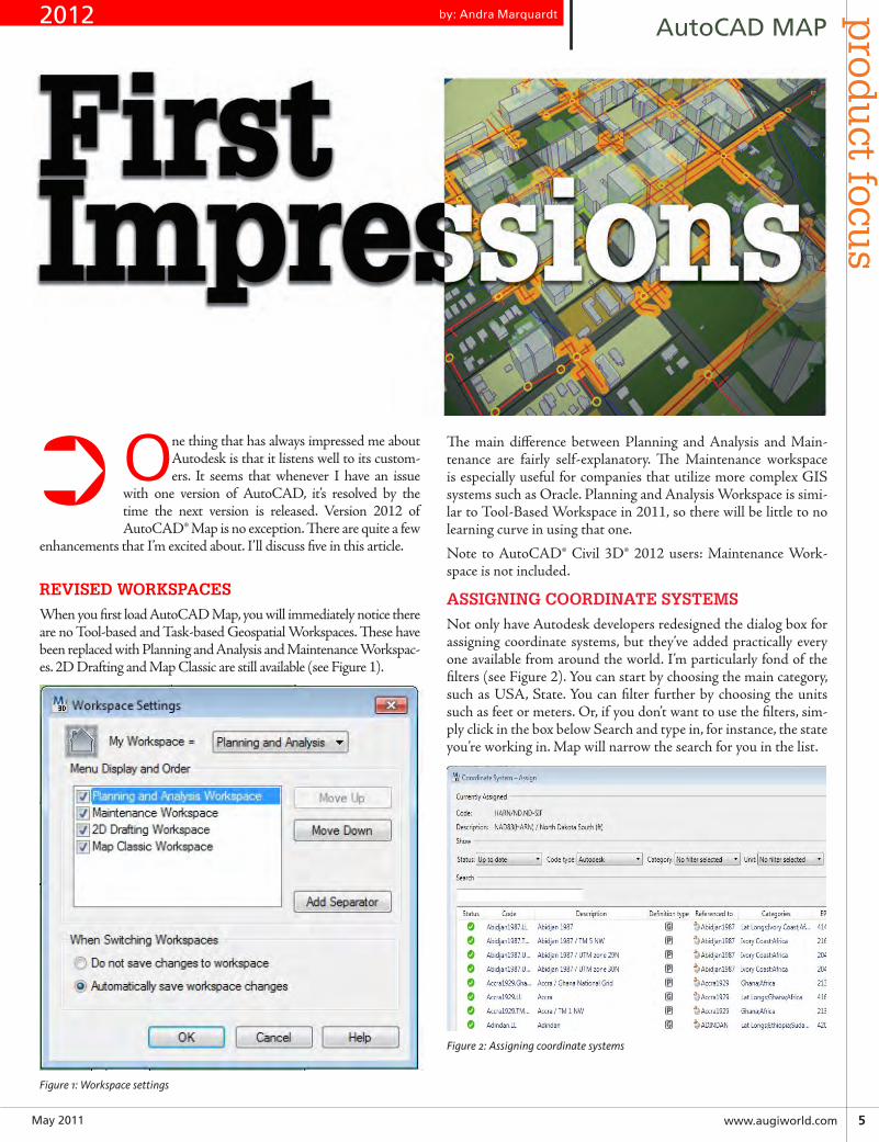
Figure 1: Workspace settings
The main difference between Planning and Analysis and Main-tenance are fairly self-explanatory. The Maintenance workspace is especially useful for companies that utilize more complex GIS systems such as Oracle. Planning and Analysis Workspace is simi-lar to Tool-Based Workspace in 2011, so there will be little to no learning curve in using that one.
Note to AutoCAD® Civil 3D® 2012 users: Maintenance Work-space is not included.
ASSIGNING COORDINATE SYSTEMS
Not only have Autodesk developers redesigned the dialog box for assigning coordinate systems, but they’ve added practically every one available from around the world. I’m particularly fond of the filters (see Figure 2). You can start by choosing the main category, such as USA, State. You can filter further by choosing the units such as feet or meters. Or, if you don’t want to use the filters, sim-ply click in the box below Search and type in, for instance, the state you’re working in. Map will narrow the search for you in the list.
Figure 2: Assigning coordinate systems
➲
by: Andra Marquardt2012
May20116 www.augi.com
pro
du
ct f
ocu
s AutoCADMAP
Be aware, if you’re upgrading from 2011, you may have trouble accessing the coordinate sys-tems. In installing on two separate computers with Civil 3D 2011 already loaded, none of the coordinate systems would show up. The only solution I found is before installing 2012, com-pletely remove 2011. That includes all associated Autodesk folders in the Program Files (and Pro-gram Files (x86) if you’re using a 64-Bit OS), the Common Files folders found in both, and under the user-name/AppData folders (usually hid-den so make sure Windows Explorer is set to view hidden folders).
FINALLY, WE CAN LINK EXCEL FILES
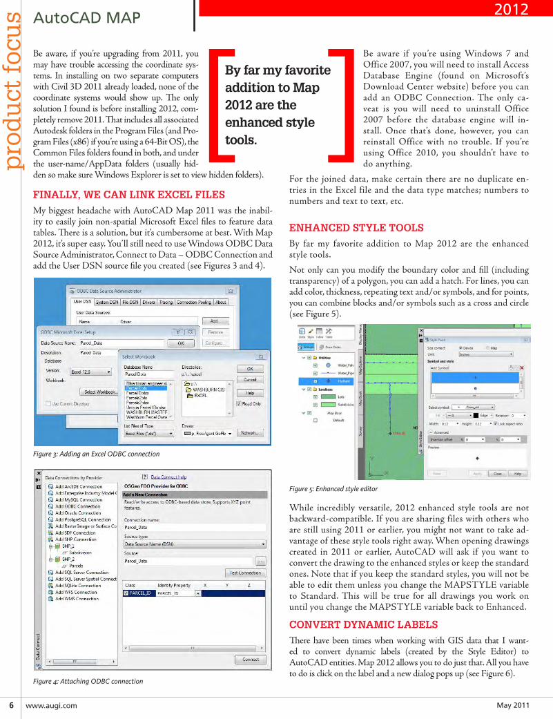
My biggest headache with AutoCAD Map 2011 was the inabil-ity to easily join non-spatial Microsoft Excel files to feature data tables. There is a solution, but it’s cumbersome at best. With Map 2012, it’s super easy. You’ll still need to use Windows ODBC Data Source Administrator, Connect to Data – ODBC Connection and add the User DSN source file you created (see Figures 3 and 4).
Figure 3: Adding an Excel ODBC connection
Figure 4: Attaching ODBC connection
Be aware if you’re using Windows 7 and Office 2007, you will need to install Access Database Engine (found on Microsoft’s Download Center website) before you can add an ODBC Connection. The only ca-veat is you will need to uninstall Office 2007 before the database engine will in-stall. Once that’s done, however, you can reinstall Office with no trouble. If you’re using Office 2010, you shouldn’t have to do anything.
For the joined data, make certain there are no duplicate en-tries in the Excel file and the data type matches; numbers to numbers and text to text, etc.
ENHANCED STYLE TOOLS
By far my favorite addition to Map 2012 are the enhanced style tools.
Not only can you modify the boundary color and fill (including transparency) of a polygon, you can add a hatch. For lines, you can add color, thickness, repeating text and/or symbols, and for points, you can combine blocks and/or symbols such as a cross and circle (see Figure 5).
Figure 5: Enhanced style editor
While incredibly versatile, 2012 enhanced style tools are not backward-compatible. If you are sharing files with others who are still using 2011 or earlier, you might not want to take ad-vantage of these style tools right away. When opening drawings created in 2011 or earlier, AutoCAD will ask if you want to convert the drawing to the enhanced styles or keep the standard ones. Note that if you keep the standard styles, you will not be able to edit them unless you change the MAPSTYLE variable to Standard. This will be true for all drawings you work on until you change the MAPSTYLE variable back to Enhanced.
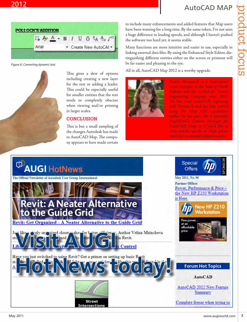
CONVERT DYNAMIC LABELS
There have been times when working with GIS data that I want-ed to convert dynamic labels (created by the Style Editor) to AutoCAD entities. Map 2012 allows you to do just that. All you have to do is click on the label and a new dialog pops up (see Figure 6).
[ ]By far my favorite addition to Map 2012 are the enhanced style tools.
2012
May2011 www.augiworld.com7
prod
uct focu
sAutoCADMAP
Figure 6: Converting dynamic text
This gives a slew of options including creating a new layer for the text or adding a leader. This could be especially useful for smaller entities that the text tends to completely obscure when viewing and/or printing in larger scales.
CONCLUSION
This is but a small sampling of the changes Autodesk has made to AutoCAD Map. The compa-ny appears to have made certain
to include many enhancements and added features that Map users have been wanting for a long time. By the same token, I’ve not seen a huge difference in loading speeds, and although I haven’t pushed the software too hard yet, it seems stable.
Many functions are more intuitive and easier to use, especially in linking external data files. By using the Enhanced Style Editor, dis-tinguishing different entities either on the screen or printout will be far easier and pleasing to the eye.
All in all, AutoCAD Map 2012 is a worthy upgrade.
Andra Marquardt is a Professional Land Surveyor in the State of North Dakota, and has worked for Toman Engineering Company since 1997. She has used AutoCAD beginning with Version 9, and has only started using the Map GIS capabilities within the last year. She is currently AugiWorld’s Content Manager for AutoCAD Map, so if you’d like to write articles specific to Map, please email her at [email protected].
2012
Visit AUGIHotNews today!
May20118 www.augi.com
pro
du
ct f
ocu
s AutoCAD
In this article, Brian Benton discusses issues to consider when implementing AutoCAD 2012. Take time to consider new features, new soft-
ware, and your company’s needs.
INTRODUCTION
Autodesk has released the next batch of its design programs and, as always, AutoCAD® is right there. CAD managers around the world are stuck with what has become an annual cycle of having to implement AutoCAD.
AutoCAD has been around for more than 25 years, so imple-menting it is nothing new. AutoCAD 2012 is the 26th release of AutoCAD. What is there to figure out? Haven’t we done this before? Is AutoCAD the new wheel that needs to be reinvented every release? Yes and no. No, its implementation doesn’t need to be reinvented, but, yes, its new features need to be considered and your company’s CAD practices need to be reevaluated.
You and your company use and implement AutoCAD in a way that has been developed by you over a series of years and installs. In the past, have you made an effort to plan out how your users will be using AutoCAD? I bet you have in at least some fashion. Did you sit down and intentionally make a plan or did you simply in-stall the program with an idea in mind? Which way sounds more likely to have a productive result?
The old cliché says “Failing to plan is planning to fail.” AutoCAD implementation works the same way. Don’t assume that simply because you’ve been using AutoCAD for decades you can auto-matically install it and be as efficient as possible. Take a few min-utes (actually more than a few) to map out the needs of your com-pany, the needs of your users, the needs of the clients, what you have to work with, and what you want the end results to be. That is your starting point.
➲
by: Brian Benton
Figure 1: Autodesk has released AutoCAD 2012, the 26th release of AutoCAD.
I don’t want to tell you how you need to implement AutoCAD. I can’t do that here. But I want to help you make sure you are con-sidering everything you need. I want to suggest a method of Auto-CAD implementation that can be taken as a starting point, a push in a good direction, in order to help you get started. And I want to let you know some of the new features and options in AutoCAD 2012 that could impact how you design.
WHERE TO START? START WITH WHAT YOU HAVE
The best place to start is at the beginning. That may sound silly, but it works. In this case, the beginning point is where you are right now. Start by looking at how many users you currently have. Evaluate them. Which ones are more advanced and can handle this update with the least amount of effort—both on their part and yours? Start the implementation with them and progress from there. Implementing an update all at once can cripple production, especially if there are unforeseen issues. The software could have a (gasp!!) bug or issue that causes harm to your data. You don’t know what a new version of software will bring. Slowly roll out the new version to your best-suited users. After a predetermined period of time, make any adjustments and move on.
IM
PLEMENTATION:
ConsiderThis
2012
May2011 www.augiworld.com9
prod
uct focu
s
IM
PLEMENTATION:
AutoCAD
Once you have evaluated your current user list, consider any changes that may be on this list. Will you be expanding it? Will you be contracting the list? You can always add more licenses of AutoCAD to the list with a quick call to your reseller, but if you have too many, that’s another issue. Make certain you have enough.
Take a good look at your hardware. Is it adequate for what you have planned? It’s difficult to know what you are going to need in the future. Inventory your current workstations. Talk to the users. See what issues they are having now. See what they like and see what they want. This inventory doesn’t mean they will get what they want, but this could give you an idea of which direction to go.
Look at the hardware specifications that Autodesk recommends for AutoCAD 2012. Take this seriously. Autodesk has spent time and effort making sure the product runs well. My advice is to get more hardware than Autodesk recommends. This will provide better performance and it will help to “future proof ” your work-stations. Remember, AutoCAD and the workstations on which it runs are the tools used daily to create your product. You need the best tool you can get for what you are trying to do. Spending a little bit extra on hardware can save you tons of cash in wasted time fighting with an inadequate machine. Make sure to get a big enough processor, video card, memory and monitor type. Provide two monitors if possible. Many firms make the mistake of assum-ing that a “gaming” computer will automatically fit the needs of AutoCAD. They don’t.
Don’t forget your network in all of this. Make sure it is also up to par. Can it handle additional workstations? Make sure that you work with your IT department during your implementation of AutoCAD 2012. A new software version rollout is a great time to evaluate how you manage files on the network.
LOOK TO THE FUTURE
The next place to look for valuable information is the future. Start up the DeLorean and take a look. This is difficult to do, I’ll admit, but it warrants a look. What will your future needs be? You would hate to spend time and money on new hardware, software, and train-ing only to find out the company is changing directions. Consider the number and types of projects you will work on. Do you have the proper number of engineers, designers, drafters, and technicians? If what you have is what you need, then proceed. If not, then what do you need? Will you need more or fewer users? Can you reassign users responsibilities? Will you need different software? How will compa-ny production policies change? All of these issues will affect how you use AutoCAD. Will AutoCAD fill your needs? Maybe it’s time to consider changing to a different software package (such as Autodesk® Revit®, Autodesk Inventor®, and AutoCAD® Civil 3D®). If AutoCAD no longer fits your needs, why implement a new version of it?
BUDGET
Price is often the real and only question. Is the price in the budget? I say the first question is “Do you have a budget?” If you do, then see if the update (software, hardware, implementation, and train-ing) fits within it. If not, well, increase the budget! Not that easy? See what you can change.
If you don’t have a budget you can make one. Start off by deter-mining your cost. Once you know how many licenses of Auto-
CAD you need, price it. Then price out hardware. You may have a set budget or you may propose a budget to the powers that be. If you propose a budget start big. List everything you need and want (don’t forget to plan for future needs.) It is much easier to bring your price down than to increase it.
Remind those who approve your budget that this money is go-ing to provide the tools needed to create your company’s product. Without these tools there will be no product. Without a product there will be no profit! We often want to skimp on the budget, but not on the work product. But skimping on the budget could cause a reduction in product quality. Don’t forget training time and implementation costs. Implementation costs could simply be the overhead cost of taking the time to install the new software or hardware.
PRODUCTION POLICIES
How do you use AutoCAD? This can be a difficult question to an-swer. But you already have an answer, whether you know it or not. It is best that you create and enforce a CAD manual, or a standards manual. This is a great time to make one. I would venture a guess that if you don’t have a manual then you have a general way of do-ing things. If you do, then you actually have a manual, even if it is unofficial. If that is the way you do things then write them down and make it official. It will make everyone’s job easier and provide a training manual of sorts, especially for new employees. Make sure to incorporate AutoCAD 2012’s new features and tools into your manual.
Also, make sure to update your customizations for any new features in AutoCAD 2012. Make sure they work, if nothing else. If you don’t customize AutoCAD, then you are missing out. A bare mini-mum customization is to use a template file. Set up at least one tem-plate file that has your units and styles preset. Add layers and title blocks as well. This will save time by streamlining your new file cre-ation procedures and improve quality control by getting every user to at least start in the same direction. Throw in a block library, tool palettes, workspaces, and profiles and you’re a regular CUI guru.
TRAINING
When times are tough, training is often the first thing to go. Who cares whether or not your employees know what they are doing, right? We don’t have much money to begin with, so why waste time ensuring the job will get done, right? Better to waste time with mistakes and inefficiency than to train, right? Doesn’t it makes great business sense to spend more than $4000 per users on a tool and not show your employees how to use it?
I am passionate about training. It needs to be done all of the time. If your company is not training you, then train yourself. AutoCAD is a complex tool with more than 800 commands and over 700 system variables. Do you know them all? These numbers alone should demonstrate why training is essential. With every re-lease, Autodesk changes this list. Some are added, some are taken away. They alter the functionality of others. These changes can also affect your company standards or methods. See what’s new and train your people. Even if you think they will never use that tool, they might come up with a use you didn’t think of. After all, they are the ones using it all day, every day.
2012
May201110 www.augi.com
pro
du
ct f
ocu
s AutoCAD
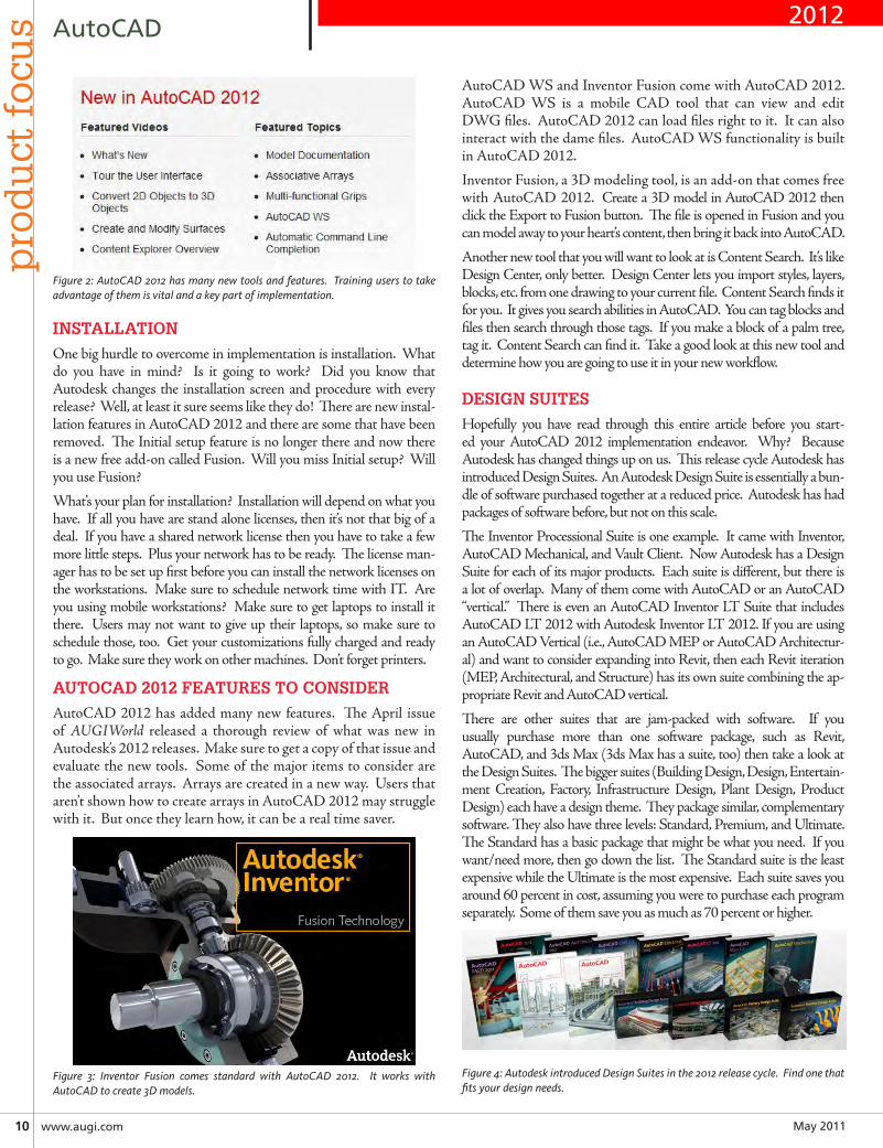
Figure 2: AutoCAD 2012 has many new tools and features. Training users to take advantage of them is vital and a key part of implementation.
INSTALLATION
One big hurdle to overcome in implementation is installation. What do you have in mind? Is it going to work? Did you know that Autodesk changes the installation screen and procedure with every release? Well, at least it sure seems like they do! There are new instal-lation features in AutoCAD 2012 and there are some that have been removed. The Initial setup feature is no longer there and now there is a new free add-on called Fusion. Will you miss Initial setup? Will you use Fusion?
What’s your plan for installation? Installation will depend on what you have. If all you have are stand alone licenses, then it’s not that big of a deal. If you have a shared network license then you have to take a few more little steps. Plus your network has to be ready. The license man-ager has to be set up first before you can install the network licenses on the workstations. Make sure to schedule network time with IT. Are you using mobile workstations? Make sure to get laptops to install it there. Users may not want to give up their laptops, so make sure to schedule those, too. Get your customizations fully charged and ready to go. Make sure they work on other machines. Don’t forget printers.
AUTOCAD 2012 FEATURES TO CONSIDER
AutoCAD 2012 has added many new features. The April issue of AUGIWorld released a thorough review of what was new in Autodesk’s 2012 releases. Make sure to get a copy of that issue and evaluate the new tools. Some of the major items to consider are the associated arrays. Arrays are created in a new way. Users that aren’t shown how to create arrays in AutoCAD 2012 may struggle with it. But once they learn how, it can be a real time saver.
Figure 3: Inventor Fusion comes standard with AutoCAD 2012. It works with AutoCAD to create 3D models.
AutoCAD WS and Inventor Fusion come with AutoCAD 2012. AutoCAD WS is a mobile CAD tool that can view and edit DWG files. AutoCAD 2012 can load files right to it. It can also interact with the dame files. AutoCAD WS functionality is built in AutoCAD 2012.
Inventor Fusion, a 3D modeling tool, is an add-on that comes free with AutoCAD 2012. Create a 3D model in AutoCAD 2012 then click the Export to Fusion button. The file is opened in Fusion and you can model away to your heart’s content, then bring it back into AutoCAD.
Another new tool that you will want to look at is Content Search. It’s like Design Center, only better. Design Center lets you import styles, layers, blocks, etc. from one drawing to your current file. Content Search finds it for you. It gives you search abilities in AutoCAD. You can tag blocks and files then search through those tags. If you make a block of a palm tree, tag it. Content Search can find it. Take a good look at this new tool and determine how you are going to use it in your new workflow.
DESIGN SUITES
Hopefully you have read through this entire article before you start-ed your AutoCAD 2012 implementation endeavor. Why? Because Autodesk has changed things up on us. This release cycle Autodesk has introduced Design Suites. An Autodesk Design Suite is essentially a bun-dle of software purchased together at a reduced price. Autodesk has had packages of software before, but not on this scale.
The Inventor Processional Suite is one example. It came with Inventor, AutoCAD Mechanical, and Vault Client. Now Autodesk has a Design Suite for each of its major products. Each suite is different, but there is a lot of overlap. Many of them come with AutoCAD or an AutoCAD “vertical.” There is even an AutoCAD Inventor LT Suite that includes AutoCAD LT 2012 with Autodesk Inventor LT 2012. If you are using an AutoCAD Vertical (i.e., AutoCAD MEP or AutoCAD Architectur-al) and want to consider expanding into Revit, then each Revit iteration (MEP, Architectural, and Structure) has its own suite combining the ap-propriate Revit and AutoCAD vertical.
There are other suites that are jam-packed with software. If you usually purchase more than one software package, such as Revit, AutoCAD, and 3ds Max (3ds Max has a suite, too) then take a look at the Design Suites. The bigger suites (Building Design, Design, Entertain-ment Creation, Factory, Infrastructure Design, Plant Design, Product Design) each have a design theme. They package similar, complementary software. They also have three levels: Standard, Premium, and Ultimate. The Standard has a basic package that might be what you need. If you want/need more, then go down the list. The Standard suite is the least expensive while the Ultimate is the most expensive. Each suite saves you around 60 percent in cost, assuming you were to purchase each program separately. Some of them save you as much as 70 percent or higher.
Figure 4: Autodesk introduced Design Suites in the 2012 release cycle. Find one that fits your design needs.
2012
May2011 www.augiworld.com11
AutoCADp
rodu
ct focus
The Design Suite is a “basic” AutoCAD-based suite. If AutoCAD fits all of your design needs, then you may want to take a look at it. The Standard Suite includes: Auto-CAD, Autodesk SketchBook Designer, Autodesk Showcase, and Autodesk Mudbox. The Premium Suite adds 3ds Max Design while the Ultimate adds Autodesk Alias Design and 3ds Max Design. What do these suites give you? Presenta-tion tools—powerful presentation tools. They provide you with more tools at little extra cost. Regular AutoCAD on subscription costs around $4,445 (MSRP) while the Stan-dard Design Suite on subscription costs $4,840 (MSRP). So for just $400 more you can get four programs where you only had one before. The Premium costs $5,470 and the Ultimate costs $6,890. You may not need 3ds Max or Alias Design. Maybe you want to give Sketchbook designer and Showcase a try. You can, at little extra cost. Maybe they can help you win more projects or just keep your current clients happy. Take a look at what the other Design Suites have to offer. Before you keep doing what you have always done, take a moment and look at the new possibilities with Au-todesk’s Design Suites. Maybe there is a software package you have wanted to try out, but found the cost prohibitive. That cost restriction may no longer exist!
CONCLUSION
If you work for a business that uses AutoCAD to produce your product (your drawings) then it is the most important tool in your company. It, and its users, must be able to function 100 percent of the time and as effectively as pos-sible. Know what you need to do and how you need to do it. Plan and provide for your production needs. Make the effort to implement your software. Take the time to train your users. Build in the time to standardize your workflow. Look to the future. Don’t be afraid of change—embrace it! Keep your workflow moving forward. New products, new tools, and new features can help you in this quest.
www.augiworld.com15April2011
AutoCADp
rodu
ct focus
The new Base View tool will take an AutoCAD or Inventor model and automatically create 2D views. The Base View tool allows you to quickly create projection views, orthogonal views, isometric, and more. It also links the model similar to an xref. If that model is updated, so is your AutoCAD file.
autodesk fusIonAutodesk Inventor® Fusion adds to the 3D conceptual de-sign tools in AutoCAD, letting you edit and validate models from many sources in a native DWG setting. When installing AutoCAD 2012 you have the option of installing Inventor Fusion. Once installed, you will have the option of opening 3D content in Inventor Fusion. You will also see an “Edit in Fusion” option when you select and right-click a 3D object in AutoCAD, if Fusion is in-stalled. Fusion gives you the ability to use direct modeling and to change your design quickly. It provides better 3D editing tools for AutoCAD, but in a more familiar environment.
autocad wsAutoCAD WS is a new tool from Autodesk that is based in the cloud. AutoCAD 2012 comes with native support for using this new tool. It allows you to upload files to AutoCAD WS from within AutoCAD. You can manage your uploads, edit files, and open them online. When you save a DWG file that you have up-loaded, AutoCAD 2012 will update the online version to match your new edits. This new integration gives you access to the Time
Line Tool. It lets you see a detailed history of the different ver-sions of your file. You can learn more about AutoCAD WS in “What’s New in AutoCAD WS” in this issue.
conclusIonAutoCAD 2012 has taken the opportunity to update many com-monly used tools. It has added more functionality to existing tools. It has expanded its 3D functionality. Inventor Fusion now comes with AutoCAD, giving users even more 3D conceptual de-sign tools. This update doesn’t have one big “gotta have it” feature, but it does have several “I could use that” additions. Now, what’s going to be in AutoCAD 2013?
Brian C. Benton is senior engineer-ing CAD technician/designer for Heidt & Associates, Inc, Fort My-ers, Florida. Brian has been working with AutoCAD since release 10 in the mechanical, structural, and civil engi-neering fields. He has been a detailer, drafter, designer, IT assistant, CAD software manager, protector of stan-dards, and proverbial “Help Desk.” He can be reached at [email protected].
Brian C. Benton has over 18 years of CAD experience in several fields. He has worked as a detailer, drafter, de-signer, Manager, & more. He writes for Cadalyst Magazine, is the AUGI World AutoCAD Content Manager, and is the author of AutoCAD train-ing videos. He can be reached through his blog: http://cad-a-blog.com
2012
May201112 www.augi.com
pro
du
ct f
ocu
s AutoCADArchitecture
by: Melinda Heavrin
The Project Navigator in AutoCAD®Architecture is the main point where you work with a project. The Drawing Manage-
ment environment within the AutoCAD Architec-ture Project Navigator helps you organize, create,
and access all your project drawings in one unified interface. Cre-ating sheets for plotting is easier with the streamlined coordina-tion that is built into the Project Navigator. The Project Navigator has four tabs that you can use to enter project data. These tabs correspond to the main phases of project creation: general project information, creating building data (con-structs), and creating building documentation (views and sheets). We will look at an overview of each of these and then will look at them more in-depth.
PROJECT CATEGORIES OVERVIEW
Each of the basic categories is represented by a folder in the Draw-ing Explorer within the project structure that helps you to orga-nize your project files. For every building project in AutoCAD Architecture, the following basic category structure is displayed on the Project tab of the Project Navigator palette:
• <ProjectName>:This is the top node in the project and is rep-resented by a folder with the project name.
• Constructs: This is the default category for constructs within the project. When you create a construct, it is saved into the Constructs category.
• Views: This is the default category for view drawings in the project. When you create a view drawing, it is saved into the Views category. It is important to note that if you create model space views within a view drawing, they will be placed under the view drawing in the same category as the view drawing itself.
• Sheets: Sheets in the project can be viewed in two ways: the Sheet Set View and the Explorer View. Each of these views will be discussed in more detail later in the article.
This main category structure is fixed, but you can create subcat-egories and subcategory trees within this structure. Subcategories typically represent aspects of your workflow. These subcategories can be set up in different ways. For example, you might set up sub-categories by discipline, by view type (presentation, section, and rendering) or by sheet type (floor plan, ceiling plan, and elevation). It is important to note that you cannot mix basic category types. For example, you cannot create a Construct subcategory within the Views category.
Categories offer excellent organization for a project. Even small building projects contain a large number of individual drawings that can be difficult to track. By putting them into descriptive categories, you can quickly find the correct files you need for your project.
THE PROJECT TAB
The Project tab on the Project Navigator tool palette is where you enter information that pertains to the entire project. The Project tab allows you to do the following:
• Change project properties
• Launch the Project Browser
• Launch the Content Browser to access the project library
• Add, modify, and delete levels
• Add, modify, and delete divisions
• Synchronize the project with project standard styles and display setting
• Enable and configure project standards
• Refresh the project
• Close the current project
Project Navigator:The Ultimate Organizer
➲
2011/2012
May2011 www.augiworld.com13
prod
uct focu
sAutoCAD
Architecture
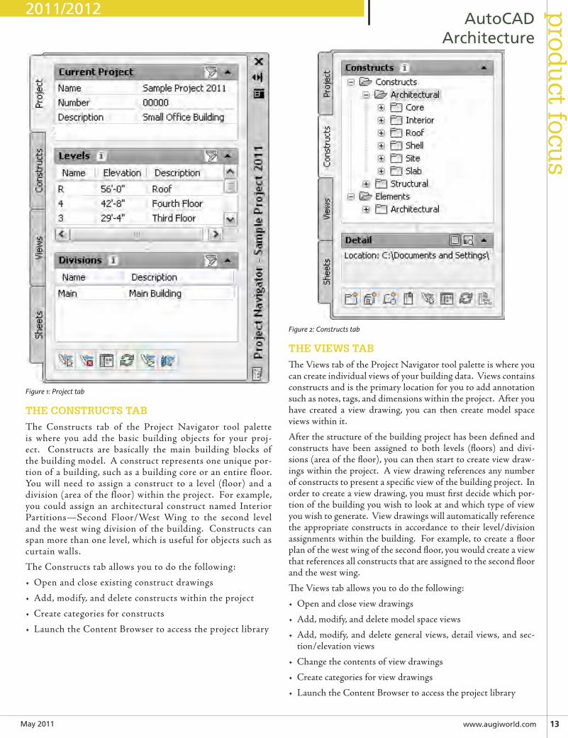
Figure 1: Project tab
THE CONSTRUCTS TAB
The Constructs tab of the Project Navigator tool palette is where you add the basic building objects for your proj-ect. Constructs are basically the main building blocks of the building model. A construct represents one unique por-tion of a building, such as a building core or an entire floor. You will need to assign a construct to a level (floor) and a division (area of the floor) within the project. For example, you could assign an architectural construct named Interior Partitions—Second Floor/West Wing to the second level and the west wing division of the building. Constructs can span more than one level, which is useful for objects such as curtain walls.
The Constructs tab allows you to do the following:
• Open and close existing construct drawings
• Add, modify, and delete constructs within the project
• Create categories for constructs
• Launch the Content Browser to access the project library
Figure 2: Constructs tab
THE VIEWS TAB
The Views tab of the Project Navigator tool palette is where you can create individual views of your building data. Views contains constructs and is the primary location for you to add annotation such as notes, tags, and dimensions within the project. After you have created a view drawing, you can then create model space views within it.
After the structure of the building project has been defined and constructs have been assigned to both levels (floors) and divi-sions (area of the floor), you can then start to create view draw-ings within the project. A view drawing references any number of constructs to present a specific view of the building project. In order to create a view drawing, you must first decide which por-tion of the building you wish to look at and which type of view you wish to generate. View drawings will automatically reference the appropriate constructs in accordance to their level/division assignments within the building. For example, to create a floor plan of the west wing of the second floor, you would create a view that references all constructs that are assigned to the second floor and the west wing.
The Views tab allows you to do the following:
• Open and close view drawings
• Add, modify, and delete model space views
• Add, modify, and delete general views, detail views, and sec-tion/elevation views
• Change the contents of view drawings
• Create categories for view drawings
• Launch the Content Browser to access the project library
2011/2012
2011/2012
May201114 www.augi.com
pro
du
ct f
ocu
s AutoCADArchitecture
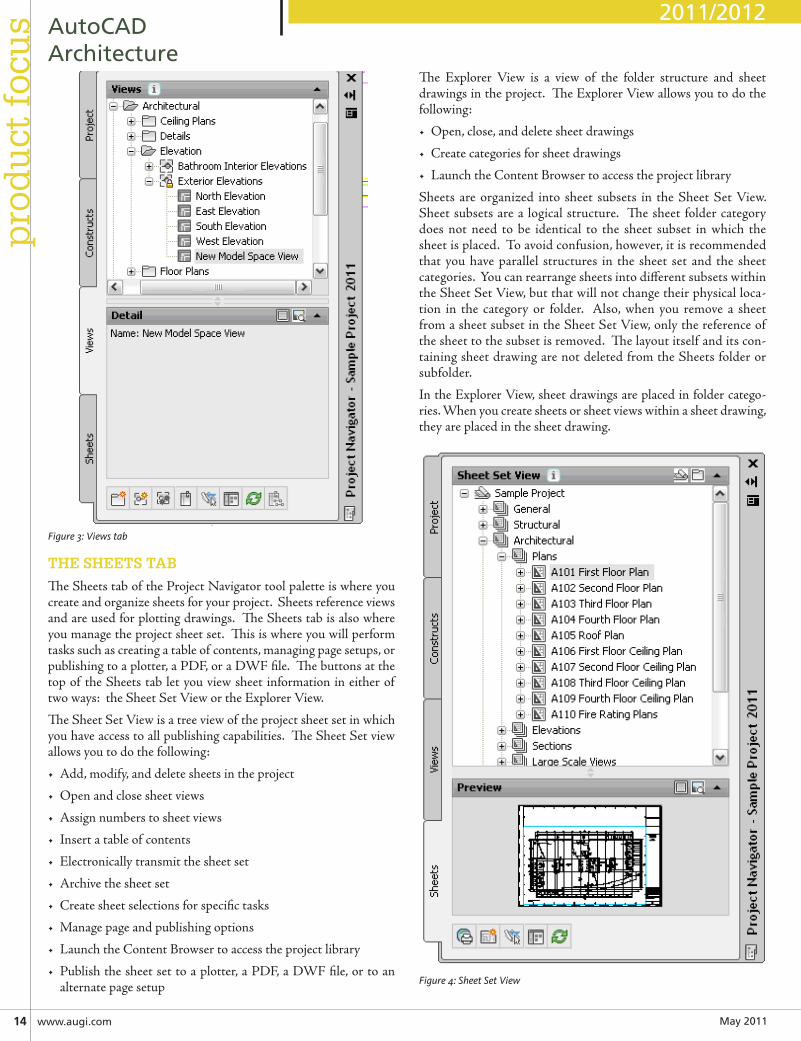
Figure 3: Views tab
THE SHEETS TAB
The Sheets tab of the Project Navigator tool palette is where you create and organize sheets for your project. Sheets reference views and are used for plotting drawings. The Sheets tab is also where you manage the project sheet set. This is where you will perform tasks such as creating a table of contents, managing page setups, or publishing to a plotter, a PDF, or a DWF file. The buttons at the top of the Sheets tab let you view sheet information in either of two ways: the Sheet Set View or the Explorer View.
The Sheet Set View is a tree view of the project sheet set in which you have access to all publishing capabilities. The Sheet Set view allows you to do the following:
• Add, modify, and delete sheets in the project
• Open and close sheet views
• Assign numbers to sheet views
• Insert a table of contents
• Electronically transmit the sheet set
• Archive the sheet set
• Create sheet selections for specific tasks
• Manage page and publishing options
• Launch the Content Browser to access the project library
• Publish the sheet set to a plotter, a PDF, a DWF file, or to an alternate page setup
The Explorer View is a view of the folder structure and sheet drawings in the project. The Explorer View allows you to do the following:
• Open, close, and delete sheet drawings
• Create categories for sheet drawings
• Launch the Content Browser to access the project library
Sheets are organized into sheet subsets in the Sheet Set View. Sheet subsets are a logical structure. The sheet folder category does not need to be identical to the sheet subset in which the sheet is placed. To avoid confusion, however, it is recommended that you have parallel structures in the sheet set and the sheet categories. You can rearrange sheets into different subsets within the Sheet Set View, but that will not change their physical loca-tion in the category or folder. Also, when you remove a sheet from a sheet subset in the Sheet Set View, only the reference of the sheet to the subset is removed. The layout itself and its con-taining sheet drawing are not deleted from the Sheets folder or subfolder.
In the Explorer View, sheet drawings are placed in folder catego-ries. When you create sheets or sheet views within a sheet drawing, they are placed in the sheet drawing.
Figure 4: Sheet Set View
2011/2012
May2011 www.augiworld.com15
prod
uct focu
sAutoCAD
Architecture
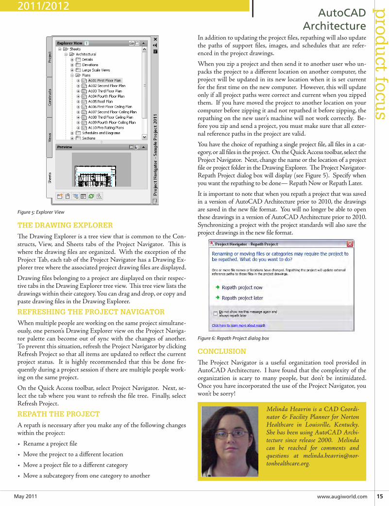
Figure 5: Explorer View
THE DRAWING EXPLORER
The Drawing Explorer is a tree view that is common to the Con-structs, View, and Sheets tabs of the Project Navigator. This is where the drawing files are organized. With the exception of the Project Tab, each tab of the Project Navigator has a Drawing Ex-plorer tree where the associated project drawing files are displayed.
Drawing files belonging to a project are displayed on their respec-tive tabs in the Drawing Explorer tree view. This tree view lists the drawings within their category. You can drag and drop, or copy and paste drawing files in the Drawing Explorer.
REFRESHING THE PROJECT NAVIGATOR
When multiple people are working on the same project simultane-ously, one person’s Drawing Explorer view on the Project Naviga-tor palette can become out of sync with the changes of another. To prevent this situation, refresh the Project Navigator by clicking Refresh Project so that all items are updated to reflect the current project status. It is highly recommended that this be done fre-quently during a project session if there are multiple people work-ing on the same project.
On the Quick Access toolbar, select Project Navigator. Next, se-lect the tab where you want to refresh the file tree. Finally, select Refresh Project.
REPATH THE PROJECT
A repath is necessary after you make any of the following changes within the project:
• Rename a project file
• Move the project to a different location
• Move a project file to a different category
• Move a subcategory from one category to another
In addition to updating the project files, repathing will also update the paths of support files, images, and schedules that are refer-enced in the project drawings.
When you zip a project and then send it to another user who un-packs the project to a different location on another computer, the project will be updated in its new location when it is set current for the first time on the new computer. However, this will update only if all project paths were correct and current when you zipped them. If you have moved the project to another location on your computer before zipping it and not repathed it before zipping, the repathing on the new user’s machine will not work correctly. Be-fore you zip and send a project, you must make sure that all exter-nal reference paths in the project are valid.
You have the choice of repathing a single project file, all files in a cat-egory, or all files in the project. On the Quick Access toolbar, select the Project Navigator. Next, change the name or the location of a project file or project folder in the Drawing Explorer. The Project Navigator- Repath Project dialog box will display (see Figure 5). Specify when you want the repathing to be done— Repath Now or Repath Later.
It is important to note that when you repath a project that was saved in a version of AutoCAD Architecture prior to 2010, the drawings are saved in the new file format. You will no longer be able to open these drawings in a version of AutoCAD Architecture prior to 2010. Synchronizing a project with the project standards will also save the project drawings in the new file format.
Figure 6: Repath Project dialog box
CONCLUSION
The Project Navigator is a useful organization tool provided in AutoCAD Architecture. I have found that the complexity of the organization is scary to many people, but don’t be intimidated. Once you have incorporated the use of the Project Navigator, you won’t be sorry!
Melinda Heavrin is a CAD Coordi-nator & Facility Planner for Norton Healthcare in Louisville, Kentucky. She has been using AutoCAD Archi-tecture since release 2000. Melinda can be reached for comments and questions at [email protected].
2011/2012
May2011 www.augiworld.com17
prod
uct focu
s AutoCADCivil3D
by: Tench Tilghman
People often make AutoCAD® Civil 3D® im-plementation too big a deal. It isn’t rocket sci-ence. Civil 3D is a software tool. It may be a
big, new tool, so a bit of caution is probably in order. The fact of the matter is, we actually already know how to do it. We’re engineers.
THE MISSION IMPOSSIBLE
“Houston. We have a problem.” Barring a miracle, the astronauts on the Apollo 13 mission are dead already when they make this call. They don’t know it. They can’t see the problem—never mind get their hands on it to fix it. Their lifetimes of knowledge, training, and skill development are next to worthless.
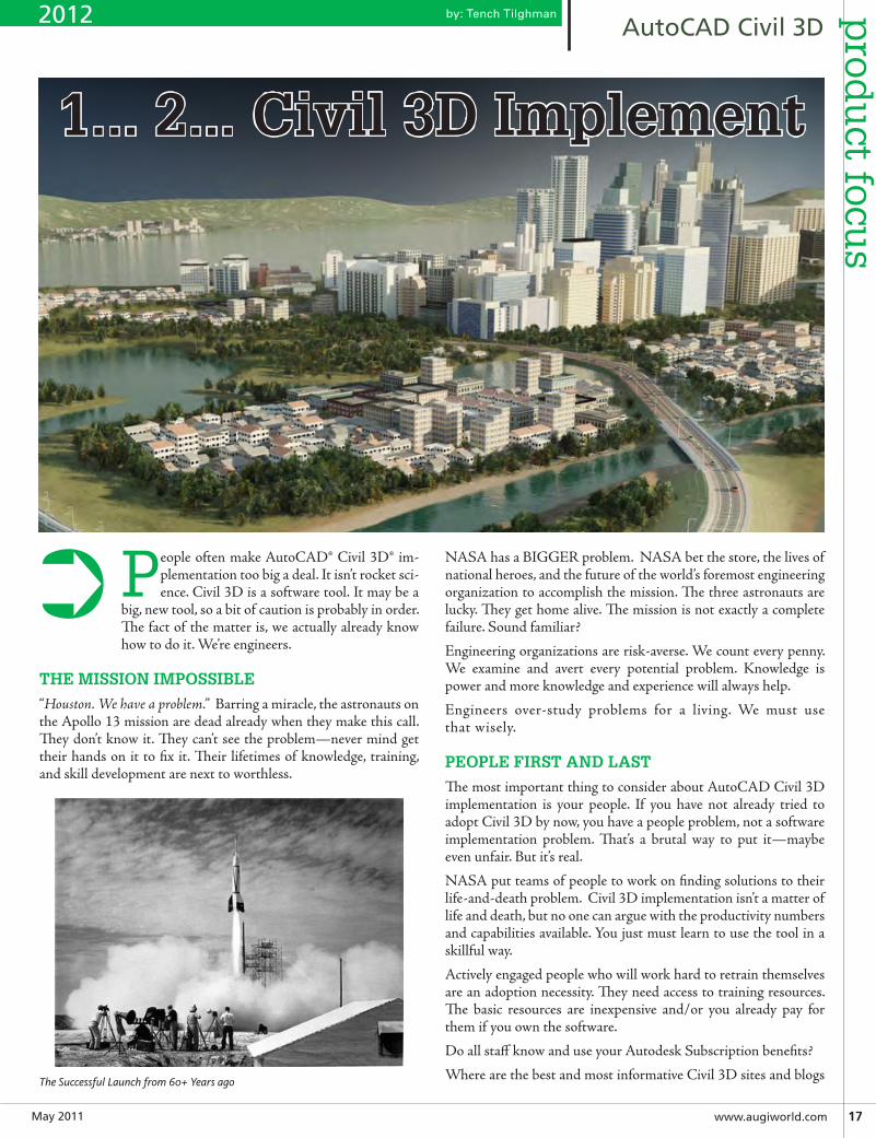
The Successful Launch from 60+ Years ago
NASA has a BIGGER problem. NASA bet the store, the lives of national heroes, and the future of the world’s foremost engineering organization to accomplish the mission. The three astronauts are lucky. They get home alive. The mission is not exactly a complete failure. Sound familiar?
Engineering organizations are risk-averse. We count every penny. We examine and avert every potential problem. Knowledge is power and more knowledge and experience will always help.
Engineers over-study problems for a living. We must use that wisely.
PEOPLE FIRST AND LAST
The most important thing to consider about AutoCAD Civil 3D implementation is your people. If you have not already tried to adopt Civil 3D by now, you have a people problem, not a software implementation problem. That’s a brutal way to put it—maybe even unfair. But it’s real.
NASA put teams of people to work on finding solutions to their life-and-death problem. Civil 3D implementation isn’t a matter of life and death, but no one can argue with the productivity numbers and capabilities available. You just must learn to use the tool in a skillful way.
Actively engaged people who will work hard to retrain themselves are an adoption necessity. They need access to training resources. The basic resources are inexpensive and/or you already pay for them if you own the software.
Do all staff know and use your Autodesk Subscription benefits?
Where are the best and most informative Civil 3D sites and blogs
1... 2... Civil 3D Implement
➲
2012
May201118www.augi.com
pro
du
ct f
ocu
s AutoCADCivil3D
on the web? Who specializes in what? Why do they do that? How can these people and firms help us?
Expect to pay for more substantive help. Good news—these days it’s a competitive marketplace. Help is always cheaper than trial and error.
EXPECT PROFESSIONAL
Engineering professionals are paid for the ability to apply working skills and experience to real-world problems. Continuing profes-sional development is our personal responsibility. This is true for firm principals, project managers, and CADpilots. The position of CAD drafter went the way of blacksmiths the day that Civil 3D software arrived. This isn’t fair. It is like gravity or the hard vacuum of space. Until the phone rings off the hook, we all have hard work to do.
THE ORGANIZATION GAME
Implementation is an organizational game. It is competitive. The larger the organization, the more competitive it should be. Implementation is managed change performed via process im-provement to stated goals. It is not an event. This is business fact, not opinion.
Well-executed, the iterative engineering methodology responds to real-world project changes and differences better and faster. The method accepts the notion that a linear project timeline is human ex-pectation and perception based. These must be proactively managed.
Model-based engineering design works based on these assump-tions: A representative model of the engineered can be built, maintained, and tested. Acceptable deliverables that allow the en-gineered to be built can be produced from the model. Your people can do this under budget, on time. Lastly, by repetition you can get better at the process of doing all of that.
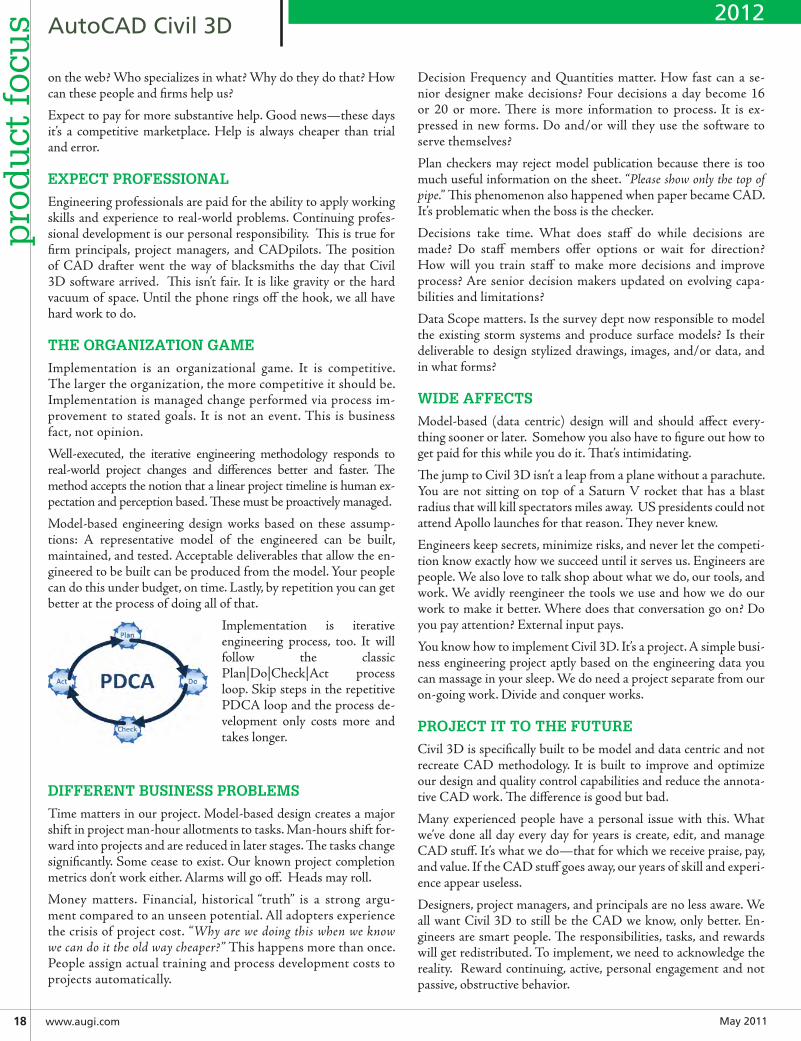
Implementation is iterativeengineering process, too. It will follow the classic Plan|Do|Check|Act process loop. Skip steps in the repetitive PDCA loop and the process de-velopment only costs more and takes longer.
DIFFERENT BUSINESS PROBLEMS
Time matters in our project. Model-based design creates a major shift in project man-hour allotments to tasks. Man-hours shift for-ward into projects and are reduced in later stages. The tasks change significantly. Some cease to exist. Our known project completion metrics don’t work either. Alarms will go off. Heads may roll.
Money matters. Financial, historical “truth” is a strong argu-ment compared to an unseen potential. All adopters experience the crisis of project cost. “Why are we doing this when we know we can do it the old way cheaper?” This happens more than once. People assign actual training and process development costs to projects automatically.
Decision Frequency and Quantities matter. How fast can a se-nior designer make decisions? Four decisions a day become 16 or 20 or more. There is more information to process. It is ex-pressed in new forms. Do and/or will they use the software to serve themselves?
Plan checkers may reject model publication because there is too much useful information on the sheet. “Please show only the top of pipe.” This phenomenon also happened when paper became CAD. It’s problematic when the boss is the checker.
Decisions take time. What does staff do while decisions are made? Do staff members offer options or wait for direction? How will you train staff to make more decisions and improve process? Are senior decision makers updated on evolving capa-bilities and limitations?
Data Scope matters. Is the survey dept now responsible to model the existing storm systems and produce surface models? Is their deliverable to design stylized drawings, images, and/or data, and in what forms?
WIDE AFFECTS
Model-based (data centric) design will and should affect every-thing sooner or later. Somehow you also have to figure out how to get paid for this while you do it. That’s intimidating.
The jump to Civil 3D isn’t a leap from a plane without a parachute. You are not sitting on top of a Saturn V rocket that has a blast radius that will kill spectators miles away. US presidents could not attend Apollo launches for that reason. They never knew.
Engineers keep secrets, minimize risks, and never let the competi-tion know exactly how we succeed until it serves us. Engineers are people. We also love to talk shop about what we do, our tools, and work. We avidly reengineer the tools we use and how we do our work to make it better. Where does that conversation go on? Do you pay attention? External input pays.
You know how to implement Civil 3D. It’s a project. A simple busi-ness engineering project aptly based on the engineering data you can massage in your sleep. We do need a project separate from our on-going work. Divide and conquer works.
PROJECT IT TO THE FUTURE
Civil 3D is specifically built to be model and data centric and not recreate CAD methodology. It is built to improve and optimize our design and quality control capabilities and reduce the annota-tive CAD work. The difference is good but bad.
Many experienced people have a personal issue with this. What we’ve done all day every day for years is create, edit, and manage CAD stuff. It’s what we do—that for which we receive praise, pay, and value. If the CAD stuff goes away, our years of skill and experi-ence appear useless.
Designers, project managers, and principals are no less aware. We all want Civil 3D to still be the CAD we know, only better. En-gineers are smart people. The responsibilities, tasks, and rewards will get redistributed. To implement, we need to acknowledge the reality. Reward continuing, active, personal engagement and not passive, obstructive behavior.
2012
May2011 www.augiworld.com19
prod
uct focu
s AutoCADCivil3D
NO MAJORS IN MINORS
Traction, Vectors, and Velocity matter. You cannot, or should not, remake Civil 3D and recreate exactly what you do today. Why not? If you focus on that, you will get exactly what you ask for. You will spend your time, attention, and human energy in the CAD weeds. Focus on the wrong details and you ignore the productive crop.
We must be practical and employ the new tool’s built-in assump-tions and advantages.
CIVIL 3D FEATURES MATTER MOST
Data centric and model-based means that Civil 3D features are more important than anything else. That’s where the data is stored; the way it is displayed and published, and where and how we create and edit the data model.
Features matter most. Every feature is a collection of components (objects). Features can and do interact with one another in a dy-namic model. Some key features are collectors and managers of the feature interactions. All the statements are true and inseparable in Civil 3D.
CAD layers are no longer the primary collector. Features are (usu-ally) contained in drawings, But a Civil 3D project is not a collec-tion of drawings like a CAD project. The Civil 3D project is more a collection of connected and/or disconnected features. This cur-rent “state” we call the “dynamic model.”
The critical path task of Civil 3D project management is then about managing these critical features and their interaction. At this point in time, the feature interaction occurs inside drawings and/or within one of the “collector” features in a drawing. Users do this work. A “managed” dynamic model is the real-world deal. Doing that depends on people understanding and always doing that work first.
Our implementation project has a feature centric structure and the structure must adapt to dynamic model changes. It must contain and track data going in and published feature data coming out. To test we need known feature data to test our tools and processes to our final delivery endpoints.
IDENTIFY AND TRACK FEATURE LIMITATIONS
All development is a work in progress. The features are not per-fect. Feature capabilities and limitations must be assessed. Are you learning the known feature limitations that may affect your work? Are you searching out a work-around before the limitation becomes a crisis? Do you reassess? Have CAD-based expectations generated false limitations? Assumption happens to expert and novice alike.
Due to the object-oriented methodology by which Civil 3D is de-veloped and maintained, our access to the features and our ability to affect them is consistent. Features do change, but how a feature works and how we can get at it cannot be significantly changed without undermining the previous work. You can bet that happens rarely. Programmers are people, too.
FEATURES ARE NOT PEOPLE
You can love or hate them, but features are not people. Fea-tures don’t care if they are understood. They don’t mind being objectified.
Feature fundamentals are in the project’s critical path. Assign the learning and delivery task to different feature mission specialists. Civil 3D training includes the care and feeding of each feature. Al-most all features have properties that can only be set on creation and every feature has properties that can be changed later. The subtle and identifiable differences are important.
LOOKS DON’T MATTER TO FEATURES
All Civil 3D feature representations and the annotations are “ab-stracted” to named style references. What features look like are sets of properties collected separately and independently. There are fea-tures that don’t separate perfectly because they are representative features anyway. We hear the words but we may misinterpret what this means to our implementation project strategy and tactics.
Our CAD perception of style and our immediate intent is to turn style into what I want. Isn’t that what style is there for? Yes and No. Features don’t care about AutoCAD stuff like layers, colors, and specifically how the features and their annotations appear. You care, but they don’t. Used wisely, our applied AutoCAD skill can pay off here.
THE POWER OF NAMES
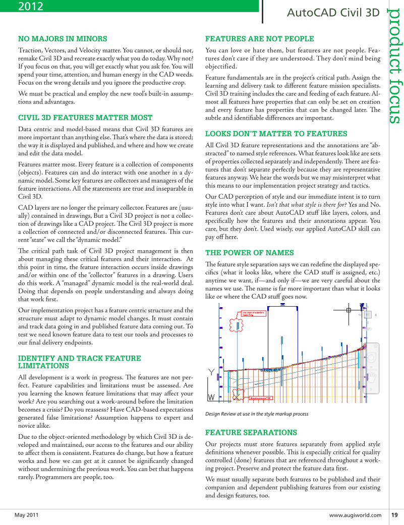
The feature style separation says we can redefine the displayed spe-cifics (what it looks like, where the CAD stuff is assigned, etc.) anytime we want, if—and only if—we are very careful about the names we use. The name is far more important than what it looks like or where the CAD stuff goes now.
Design Review at use in the style markup process
FEATURE SEPARATIONS
Our projects must store features separately from applied style definitions whenever possible. This is especially critical for quality controlled (done) features that are referenced throughout a work-ing project. Preserve and protect the feature data first.
We must usually separate both features to be published and their companion and dependent publishing features from our existing and design features, too.
2012
May201120www.augi.com
pro
du
ct f
ocu
s AutoCADCivil3D
Our project has create and edit drawings (model drawings), ref-erence drawings, collector drawings, and multiple forms of pub-lish drawings.
How many Civil 3D templates do we need? One template will nev-er work. How many styles and sets do we need? In practice this is potentially a staggering and overwhelming number. You don’t need all of them all at once. Process first.
THE IMPLEMENTATION PROJECT DEFINITION
All the pieces of our implementation project are built into Civil 3D by the software’s own scope definition. They ship with it. The examples may be inadequate or bad from our perspective, but the parts and pieces are all there. Be wary of adding more. KISS.
TheCivil3DProjectTemplate – this is the core working project structure, the container for your approved in-use resources, your backup and archival strategy, and ultimately your delivery method to the troops. It represents the current “approved” snapshot of our on-going implementation project. All the rest is in here.
TheSheetSetTemplateandSheetTemplates – these define the published model output in Civil 3D. There is a folder structure, naming conventions, standard resources, and methods to hold that buried in here. If the daily project quality control and check loops do not happen here, plans become the crisis.
Civil3DModeltemplates – these contain the styles and set tools we need to create, edit, maintain, and publish the model features. The Civil 3D template is the Holy Grail of implementation. The good news? You can now avoid that work as much as possible.
Engineers are smart people. Don’t reinvent the wheel. Build on known standards of your choosing. Build on the work of others. Go find that. You know more about what to look for and how to judge it. It is out there.
“We have liftoff…”
Tench Tilghman writes the Get the Jump on Civil 3D blog. He is Presi-dent of MoreCompetency, Inc., an Autodesk Developer Partner, special-izing in innovative Civil 3D adoption products and consulting services. He is a regular speaker at Autodesk Uni-versity and AEC industry events on the topics of technology adoption, in-novation, and (his personal favorite) people skills.
2012
VisitAUGI Forums today!
May2011 www.augiworld.com21
dep
artmen
tby: James Salmon
SIMPLIFYING THE COMPLEX
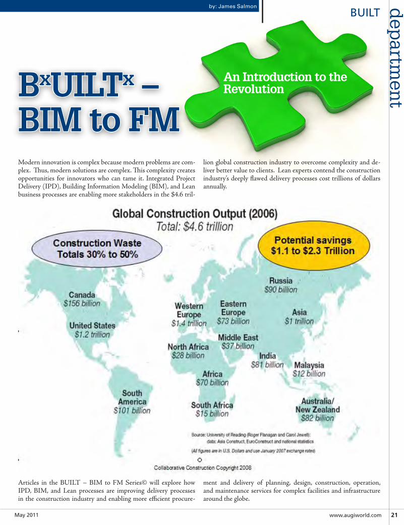
Modern innovation is complex because modern problems are com-plex. Thus, modern solutions are complex. This complexity creates opportunities for innovators who can tame it. Integrated Project Delivery (IPD), Building Information Modeling (BIM), and Lean business processes are enabling more stakeholders in the $4.6 tril-
lion global construction industry to overcome complexity and de-liver better value to clients. Lean experts contend the construction industry’s deeply flawed delivery processes cost trillions of dollars annually.
Articles in the BUILT – BIM to FM Series© will explore how IPD, BIM, and Lean processes are improving delivery processes in the construction industry and enabling more efficient procure-
ment and delivery of planning, design, construction, operation, and maintenance services for complex facilities and infrastructure around the globe.
BxUILTx –BIM to FM
An Introduction to the Revolution
BUILT
May201122 www.augi.com
dep
artm
ent BUILT
THE FRAGMENTED – AND INEFFICIENT – CONSTRUCTION INDUSTRY
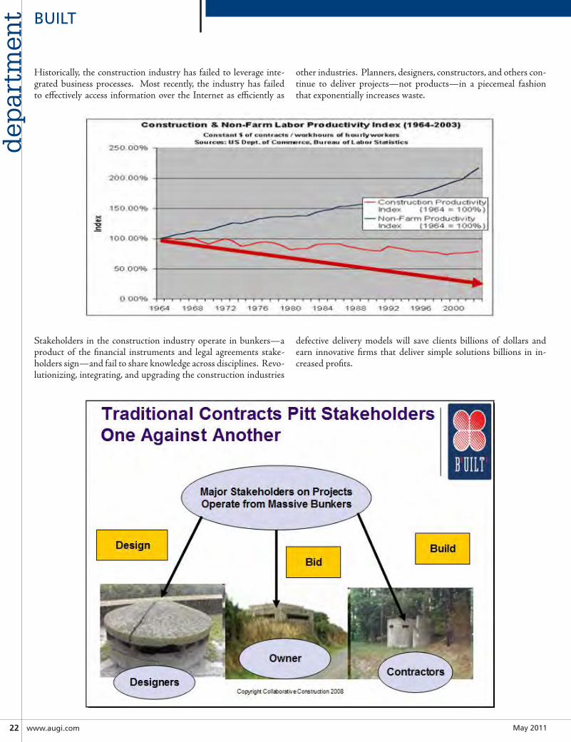
Historically, the construction industry has failed to leverage inte-grated business processes. Most recently, the industry has failed to effectively access information over the Internet as efficiently as
other industries. Planners, designers, constructors, and others con-tinue to deliver projects—not products—in a piecemeal fashion that exponentially increases waste.
Stakeholders in the construction industry operate in bunkers—a product of the financial instruments and legal agreements stake-holders sign—and fail to share knowledge across disciplines. Revo-lutionizing, integrating, and upgrading the construction industries
defective delivery models will save clients billions of dollars and earn innovative firms that deliver simple solutions billions in in-creased profits.
May2011 www.augiworld.com23
dep
artmen
tBUILT
SOPHISTICATED OWNERS WILL DEMAND INTEGRATED DIGITAL ASSETS
Manufacturers pioneered business process integration and are now reaping benefits globally. Conceptualization, design, fabrication, sales, distribution, warranties, service, and every other facet of a product’s life cycle can be tracked by a sophis-ticated manufacturer. Operating on sophisticated, enterprise-level software platforms, manufacturers routinely track their products throughout their life cycles, enhancing consumer satisfaction and increasing profits. By mirroring those efforts, integrated teams in the construction industry can use IPD, BIM, and Lean processes to solve complex facilities and infra-structure puzzles.
Currently, there are few in the construction industry com-mitted to solving those puzzles. Planners, owners, designers, constructors, and other stakeholders treat facilities and in-frastructure as one-off projects rather than repeatable prod-ucts. However, emerging market forces—driven in large part by economic and environmental concerns and government mandates—are putting pressure on the fragmented and dys-functional construction industry to deliver high-performance buildings and infrastructure that increase energy efficiency and add value. This cannot be done effectively until stake-holders in the construction industry recognize the value of integration. Sophisticated owners are beginning to demand BIM to FM, and innovators who deliver cost-effective solu-tions to those owners will earn billions.
THE BUILT – BIM TO FM SERIES
James L. Salmon, the founder of Collaborative Construction Resources will oversee the BUILT – BIM to FM series and will be co-authoring articles in this series with innovators from around the globe. The articles will be premised on Col-laborative Construction concept of BxUILTx Solutions©, an acronym coined by Collaborative Construction that referenc-es facilities and infrastructure, “Built by BIM Builders Utiliz-ing IPD, BIM and Lean Technologies Today and Tomorrow.” The phrase, “BIM to FM” refers to the need to capture digi-tal assets authoritatively throughout the life cycle and deliver those digital assets to facilities management personnel and software programs as part of a fully functional and integrated Building Information Model.
In the coming months we will explore the mechanisms for deliv-ering BIM to FM in a BxUILTx Environment©. We will con-sider the legal framework required, the best practices for trust based team building, the use of strategic alliance agreements by cluster groups, ROI on IPD, BIM, and Lean, use of alternative dispute resolution in a BxUILTx Environment©, and other top-ics. If you are interested in co-authoring an article in the series please contact James L. Salmon at [email protected].
James L. Salmon, Esq. President, Collaborative Construction Re-sources, LLC is a collaborative consultant and the creator of these IPD in 3D™ concepts. Salmon ad-vocates the use of advanced BIM technologies, Lean Construction methods, Collaborative Agree-ments and other IPD in 3D™ processes. His Collaborative BIM Advocates group provides free membership, national networking opportunities, custom symposiums and online webinars.

May201124 www.augi.com
pro
du
ct f
ocu
s RevitArchitecture
Whenever a new software release comes around, you need to evaluate it according to at least these two questions:
1. How valuable are the new or improved features to me and my firm?and
2. How much will any of these new or improved features poten-tially change my firm’s current workflow… and in a positive or negative way?
by Joe Eichenseer and Scott Burke
➲If you’re reading this article, you’ve probably already seen other media describing what’s new in Autodesk® Revit® Architecture 2012, and we’re certainly not going to revisit that here. (Check out the April 2011 issue of AUGIWorld for a “What’s New” overview.) Knowing what’s new allows you to start to evaluate question #1, but in order to really understand your personal answer to question #2, you need to have a deeper understanding of both the features and your firm. This article will focus on a few key features in Revit Architecture as they relate to the second question.
2012
May2011 www.augiworld.com25
prod
uct focu
sRevitArchitecture
TAGGING ELEMENTS IN LINKED FILES
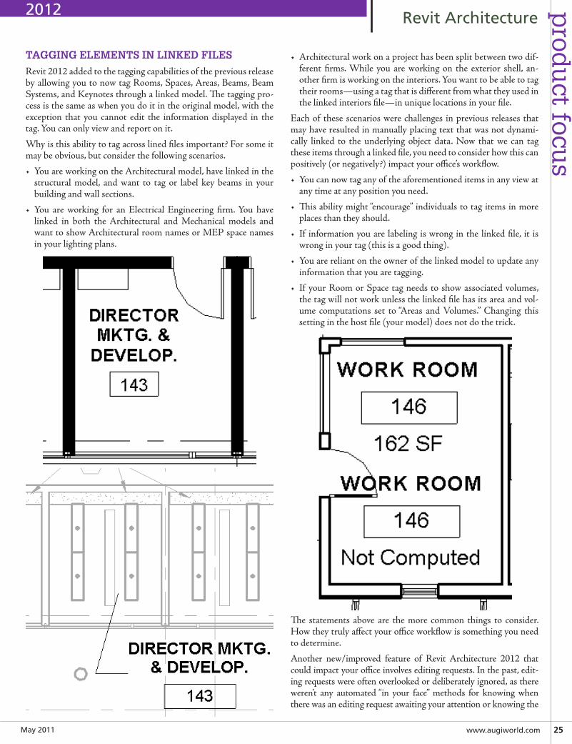
Revit 2012 added to the tagging capabilities of the previous release by allowing you to now tag Rooms, Spaces, Areas, Beams, Beam Systems, and Keynotes through a linked model. The tagging pro-cess is the same as when you do it in the original model, with the exception that you cannot edit the information displayed in the tag. You can only view and report on it.
Why is this ability to tag across lined files important? For some it may be obvious, but consider the following scenarios.
• You are working on the Architectural model, have linked in the structural model, and want to tag or label key beams in your building and wall sections.
• You are working for an Electrical Engineering firm. You have linked in both the Architectural and Mechanical models and want to show Architectural room names or MEP space names in your lighting plans.
• Architectural work on a project has been split between two dif-ferent firms. While you are working on the exterior shell, an-other firm is working on the interiors. You want to be able to tag their rooms—using a tag that is different from what they used in the linked interiors file—in unique locations in your file.
Each of these scenarios were challenges in previous releases that may have resulted in manually placing text that was not dynami-cally linked to the underlying object data. Now that we can tag these items through a linked file, you need to consider how this can positively (or negatively?) impact your office’s workflow.
• You can now tag any of the aforementioned items in any view at any time at any position you need.
• This ability might “encourage” individuals to tag items in more places than they should.
• If information you are labeling is wrong in the linked file, it is wrong in your tag (this is a good thing).
• You are reliant on the owner of the linked model to update any information that you are tagging.
• If your Room or Space tag needs to show associated volumes, the tag will not work unless the linked file has its area and vol-ume computations set to “Areas and Volumes.” Changing this setting in the host file (your model) does not do the trick.
The statements above are the more common things to consider. How they truly affect your office workflow is something you need to determine.
Another new/improved feature of Revit Architecture 2012 that could impact your office involves editing requests. In the past, edit-ing requests were often overlooked or deliberately ignored, as there weren’t any automated “in your face” methods for knowing when there was an editing request awaiting your attention or knowing the
2012
May201126 www.augi.com
pro
du
ct f
ocu
s RevitArchitecture
status of any editing requests that you may have placed. Autodesk provided a Worksharing Monitor that helped, but because it was a secondary installation, not everyone knew about its existence, regu-larly used it, or paid attention to what it was trying to tell you.
For these reasons, you might not be familiar with editing requests, so here is a quick run-down. If you are working in a multi-user / workset-enabled environment, from time to time you may try to edit a building component that is already owned by another team member. When this happens, you will get a message on screen let-ting you know the object is already locked down and then provide you an opportunity to place an editing request. If the request is granted, you will be able to edit that specific object.
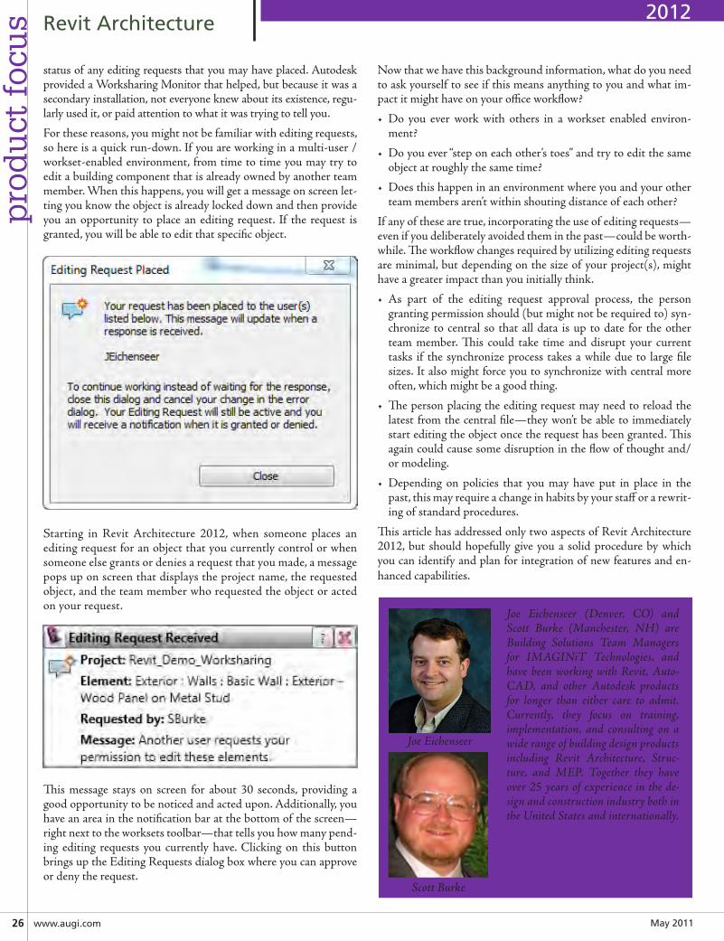
Starting in Revit Architecture 2012, when someone places an editing request for an object that you currently control or when someone else grants or denies a request that you made, a message pops up on screen that displays the project name, the requested object, and the team member who requested the object or acted on your request.
This message stays on screen for about 30 seconds, providing a good opportunity to be noticed and acted upon. Additionally, you have an area in the notification bar at the bottom of the screen—right next to the worksets toolbar—that tells you how many pend-ing editing requests you currently have. Clicking on this button brings up the Editing Requests dialog box where you can approve or deny the request.
Now that we have this background information, what do you need to ask yourself to see if this means anything to you and what im-pact it might have on your office workflow?
• Do you ever work with others in a workset enabled environ-ment?
• Do you ever “step on each other’s toes” and try to edit the same object at roughly the same time?
• Does this happen in an environment where you and your other team members aren’t within shouting distance of each other?
If any of these are true, incorporating the use of editing requests—even if you deliberately avoided them in the past—could be worth-while. The workflow changes required by utilizing editing requests are minimal, but depending on the size of your project(s), might have a greater impact than you initially think.
• As part of the editing request approval process, the person granting permission should (but might not be required to) syn-chronize to central so that all data is up to date for the other team member. This could take time and disrupt your current tasks if the synchronize process takes a while due to large file sizes. It also might force you to synchronize with central more often, which might be a good thing.
• The person placing the editing request may need to reload the latest from the central file—they won’t be able to immediately start editing the object once the request has been granted. This again could cause some disruption in the flow of thought and/or modeling.
• Depending on policies that you may have put in place in the past, this may require a change in habits by your staff or a rewrit-ing of standard procedures.
This article has addressed only two aspects of Revit Architecture 2012, but should hopefully give you a solid procedure by which you can identify and plan for integration of new features and en-hanced capabilities.
2012
Joe Eichenseer (Denver, CO) and Scott Burke (Manchester, NH) are Building Solutions Team Managers for IMAGINiT Technologies, and have been working with Revit, Auto-CAD, and other Autodesk products for longer than either care to admit. Currently, they focus on training, implementation, and consulting on a wide range of building design products including Revit Architecture, Struc-ture, and MEP. Together they have over 25 years of experience in the de-sign and construction industry both in the United States and internationally.
Joe Eichenseer
Scott Burke
May201128 www.augi.com
pro
du
ct f
ocu
s RevitArchitectureby: Miriam Ganesh and Damian Serrano
THE
It is typically said that Revit is not a user-friendly tool for interior designers in terms of the way they document their work. While it may be true
that Revit still needs to address some of the require-
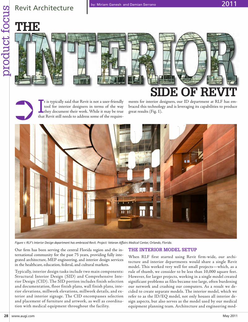
ments for interior designers, our ID department at RLF has em-braced this technology and is leveraging its capabilities to produce great results (Fig. 1).➲
Our firm has been serving the central Florida region and the in-ternational community for the past 75 years, providing fully inte-grated architecture, MEP engineering, and interior design services in the healthcare, education, federal, and cultural markets.
Typically, interior design tasks include two main components: Structural Interior Design (SID) and Comprehensive Inte-rior Design (CID). The SID portion includes finish selection and documentation, floor finish plans, wall finish plans, inte-rior elevations, millwork elevations, millwork details, and ex-terior and interior signage. The CID encompasses selection and placement of furniture and artwork, as well as coordina-tion with medical equipment throughout the facility.
THE INTERIOR MODEL SETUP
When RLF first started using Revit firm-wide, our archi-tecture and interior departments would share a single Revit model. This worked very well for small projects—which, as a rule of thumb, we consider to be less than 10,000 square feet. However, for larger projects, working in a single model created significant problems as files became too large, often burdening our network and crashing our computers. As a result we de-cided to create separate models. The interior model, which we refer to as the ID/EQ model, not only houses all interior de-sign aspects, but also serves as the model used by our medical equipment planning team. Architecture and engineering mod-
Figure 1: RLF’s Interior Design department has embraced Revit. Project: Veteran Affairs Medical Center, Orlando, Florida.
SIDE OF REVIT
2011
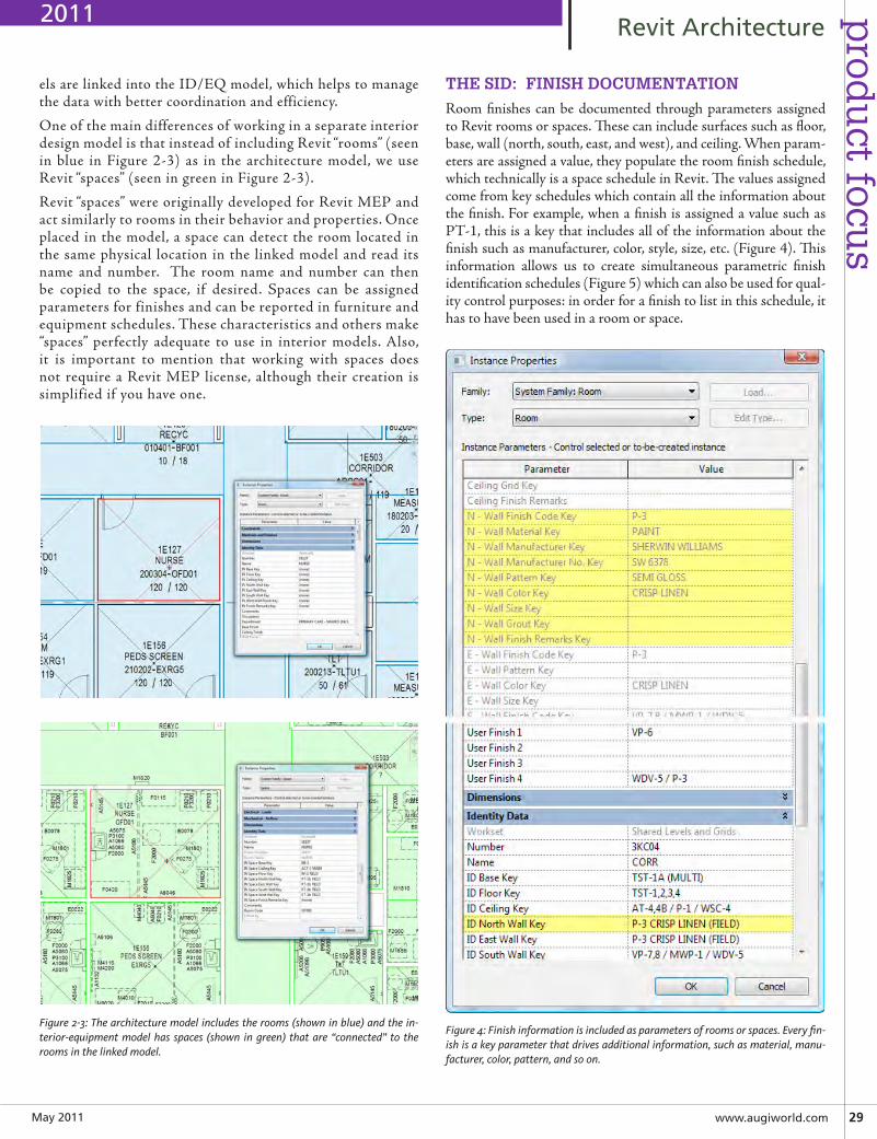
May2011 www.augiworld.com29
prod
uct focu
sRevitArchitecture
THE SID: FINISH DOCUMENTATION
Room finishes can be documented through parameters assigned to Revit rooms or spaces. These can include surfaces such as floor, base, wall (north, south, east, and west), and ceiling. When param-eters are assigned a value, they populate the room finish schedule, which technically is a space schedule in Revit. The values assigned come from key schedules which contain all the information about the finish. For example, when a finish is assigned a value such as PT-1, this is a key that includes all of the information about the finish such as manufacturer, color, style, size, etc. (Figure 4). This information allows us to create simultaneous parametric finish identification schedules (Figure 5) which can also be used for qual-ity control purposes: in order for a finish to list in this schedule, it has to have been used in a room or space.
Figure 4: Finish information is included as parameters of rooms or spaces. Every fin-ish is a key parameter that drives additional information, such as material, manu-facturer, color, pattern, and so on.
els are linked into the ID/EQ model, which helps to manage the data with better coordination and efficiency.
One of the main differences of working in a separate interior design model is that instead of including Revit “rooms” (seen in blue in Figure 2-3) as in the architecture model, we use Revit “spaces” (seen in green in Figure 2-3).
Revit “spaces” were originally developed for Revit MEP and act similarly to rooms in their behavior and properties. Once placed in the model, a space can detect the room located in the same physical location in the linked model and read its name and number. The room name and number can then be copied to the space, if desired. Spaces can be assigned parameters for finishes and can be reported in furniture and equipment schedules. These characteristics and others make “spaces” perfectly adequate to use in interior models. Also, it is important to mention that working with spaces does not require a Revit MEP license, although their creation is simplified if you have one.
Figure 2-3: The architecture model includes the rooms (shown in blue) and the in-terior-equipment model has spaces (shown in green) that are “connected” to the rooms in the linked model.
2011
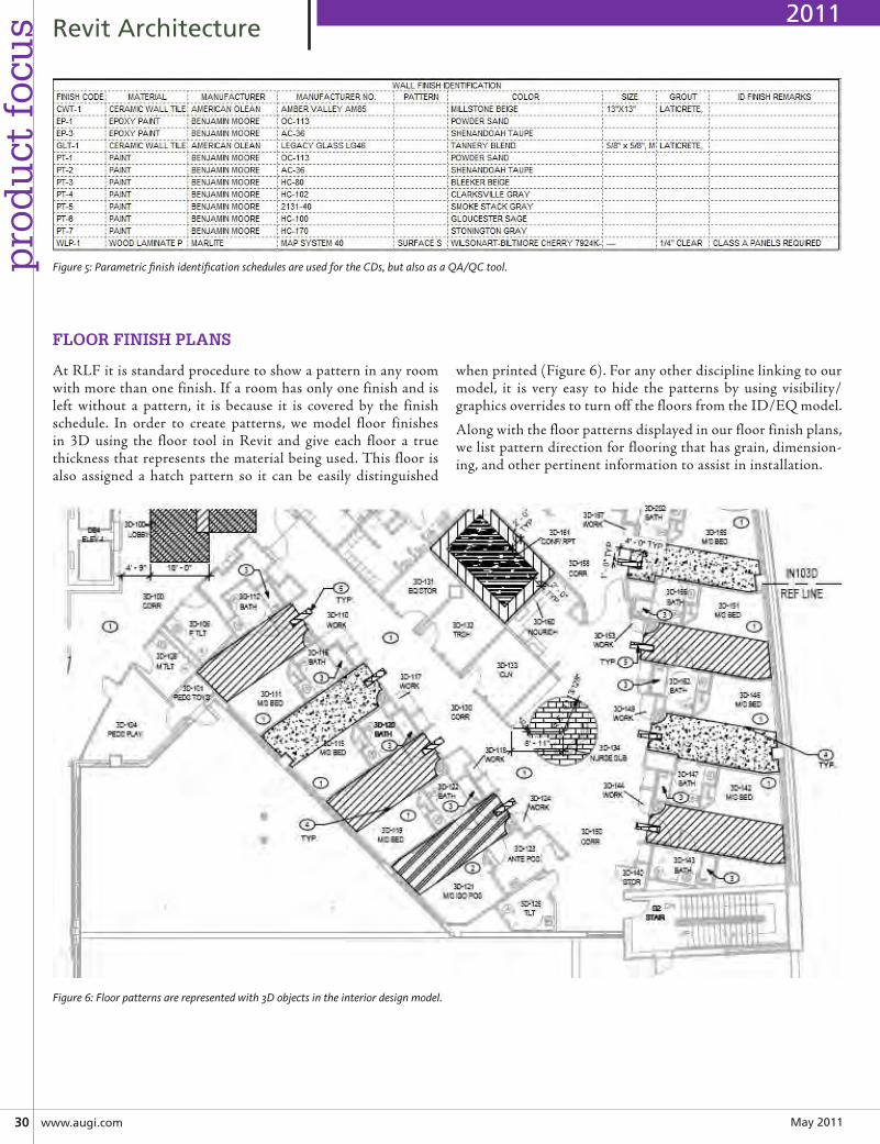
May201130 www.augi.com
pro
du
ct f
ocu
s RevitArchitecture
At RLF it is standard procedure to show a pattern in any room with more than one finish. If a room has only one finish and is left without a pattern, it is because it is covered by the finish schedule. In order to create patterns, we model floor finishes in 3D using the floor tool in Revit and give each floor a true thickness that represents the material being used. This floor is also assigned a hatch pattern so it can be easily distinguished
when printed (Figure 6). For any other discipline linking to our model, it is very easy to hide the patterns by using visibility/graphics overrides to turn off the floors from the ID/EQ model.
Along with the floor patterns displayed in our floor finish plans, we list pattern direction for flooring that has grain, dimension-ing, and other pertinent information to assist in installation.
Figure 5: Parametric finish identification schedules are used for the CDs, but also as a QA/QC tool.
Figure 6: Floor patterns are represented with 3D objects in the interior design model.
FLOOR FINISH PLANS
2011
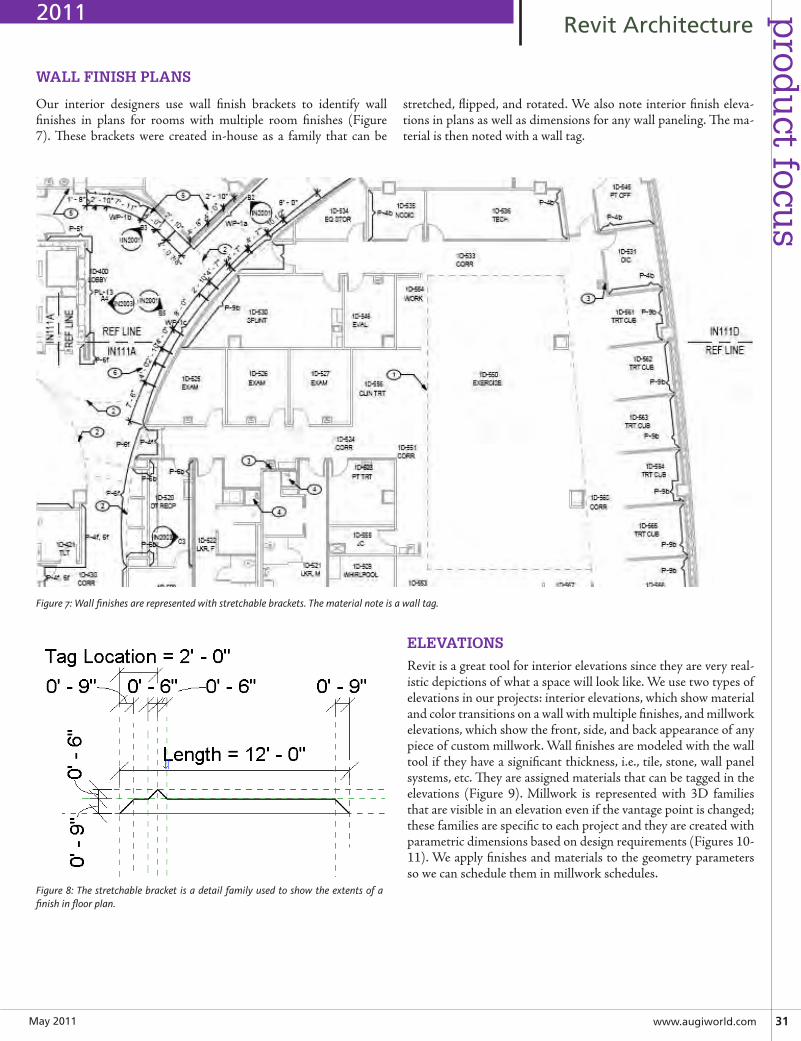
May2011 www.augiworld.com31
prod
uct focu
sRevitArchitecture
Figure 8: The stretchable bracket is a detail family used to show the extents of a finish in floor plan.
ELEVATIONS
Revit is a great tool for interior elevations since they are very real-istic depictions of what a space will look like. We use two types of elevations in our projects: interior elevations, which show material and color transitions on a wall with multiple finishes, and millwork elevations, which show the front, side, and back appearance of any piece of custom millwork. Wall finishes are modeled with the wall tool if they have a significant thickness, i.e., tile, stone, wall panel systems, etc. They are assigned materials that can be tagged in the elevations (Figure 9). Millwork is represented with 3D families that are visible in an elevation even if the vantage point is changed; these families are specific to each project and they are created with parametric dimensions based on design requirements (Figures 10-11). We apply finishes and materials to the geometry parameters so we can schedule them in millwork schedules.
Our interior designers use wall finish brackets to identify wall finishes in plans for rooms with multiple room finishes (Figure 7). These brackets were created in-house as a family that can be
stretched, flipped, and rotated. We also note interior finish eleva-tions in plans as well as dimensions for any wall paneling. The ma-terial is then noted with a wall tag.
WALL FINISH PLANS
Figure 7: Wall finishes are represented with stretchable brackets. The material note is a wall tag.
2011
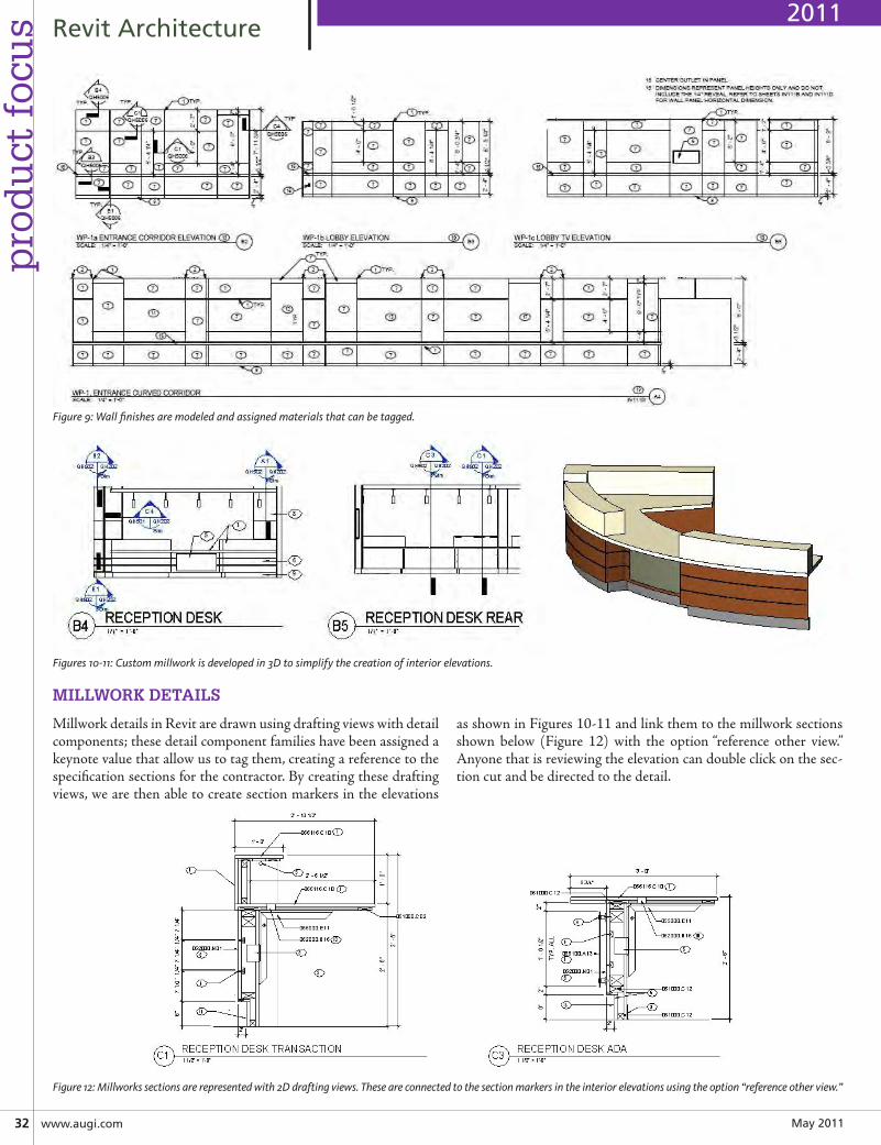
May201132 www.augi.com
pro
du
ct f
ocu
s RevitArchitecture
Figure 9: Wall finishes are modeled and assigned materials that can be tagged.
Figures 10-11: Custom millwork is developed in 3D to simplify the creation of interior elevations.
MILLWORK DETAILS
Millwork details in Revit are drawn using drafting views with detail components; these detail component families have been assigned a keynote value that allow us to tag them, creating a reference to the specification sections for the contractor. By creating these drafting views, we are then able to create section markers in the elevations
as shown in Figures 10-11 and link them to the millwork sections shown below (Figure 12) with the option “reference other view.” Anyone that is reviewing the elevation can double click on the sec-tion cut and be directed to the detail.
Figure 12: Millworks sections are represented with 2D drafting views. These are connected to the section markers in the interior elevations using the option “reference other view.”
2011
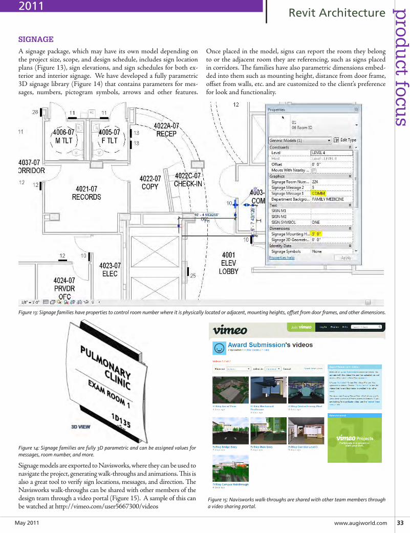
May2011 www.augiworld.com33
prod
uct focu
sRevitArchitecture
SIGNAGE
A signage package, which may have its own model depending on the project size, scope, and design schedule, includes sign location plans (Figure 13), sign elevations, and sign schedules for both ex-terior and interior signage. We have developed a fully parametric 3D signage library (Figure 14) that contains parameters for mes-sages, numbers, pictogram symbols, arrows and other features.
Once placed in the model, signs can report the room they belong to or the adjacent room they are referencing, such as signs placed in corridors. The families have also parametric dimensions embed-ded into them such as mounting height, distance from door frame, offset from walls, etc. and are customized to the client’s preference for look and functionality.
Figure 13: Signage families have properties to control room number where it is physically located or adjacent, mounting heights, offset from door frames, and other dimensions.
Figure 14: Signage families are fully 3D parametric and can be assigned values for messages, room number, and more.
Figure 15: Navisworks walk-throughs are shared with other team members through a video sharing portal.
Signage models are exported to Navisworks, where they can be used to navigate the project, generating walk-throughs and animations. This is also a great tool to verify sign locations, messages, and direction. The Navisworks walk-throughs can be shared with other members of the design team through a video portal (Figure 15). A sample of this can be watched at http://vimeo.com/user5667300/videos
2011
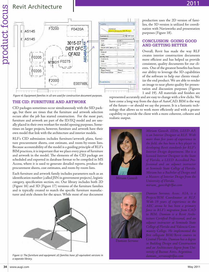
May201134 www.augi.com
pro
du
ct f
ocu
s RevitArchitecture
THE CID: FURNITURE AND ARTWORK
CID packages sometimes occur simultaneously with the SID pack-age, but there are times that the furniture and artwork selection occurs after the job has started construction. For the most part, furniture and artwork are part of the ID/EQ model and are usu-ally placed in their own workset for model opening purposes. Some-times on larger projects, however, furniture and artwork have their own model that link with the architecture and interior models.
RLF’s CID submission includes furniture/artwork plans, furni-ture procurement sheets, cost estimate, and room-by-room lists. Because accountability of the model is a guiding principle of RLF’s BIM practices, it is important that we place every piece of furniture and artwork in the model. The elements of the CID package are scheduled and exported in database format to be compiled in MS Access, where it is used to generate detailed reports, produce the procurement sheets, cost estimates, and room-by-room lists.
Each furniture and artwork family includes parameters such as an identification number (called JSN in government projects), logistic category, specification section, etc. Our library includes both 2D (Figure 16) and 3D (Figure 17) versions of the furniture families and is typically created to match the specific furniture manufac-turer and style chosen for the space. While most of our document
production uses the 2D version of fami-lies, the 3D version is utilized for coordi-nation with Navisworks and presentation purposes (Figure 18).
CONCLUSION: GOING GOOD AND GETTING BETTER
Overall, Revit has made the way RLF creates interior construction documents more efficient and has helped us provide consistent, quality documents for our cli-ents. One of the greatest benefits has been our ability to leverage the 3D capabilities of the software to help our clients visual-ize the end product. We are able to render an image to near photo quality for presen-tation and discussion purposes (Figures 1 and 19). All materials and finishes are
represented accurately and are easy to change with a few clicks. We have come a long way from the days of AutoCAD. BIM is the way of the future—or should we say the present. It is a fantastic tech-nology that allows us to work more efficiently and with a greater capability to provide the client with a more coherent, cohesive and realistic output.
Miriam Ganesh, IIDA, LEED AP, is an Interior Designer at RLF. With more than five years of experience in the field, she has been a key player in developing Revit standards for RLF’s Interior Design department. She is a licensed Interior Designer in the State of Florida, a LEED Accredited Pro-fessional and an adjunct instructor at Seminole State College of Florida. Miriam has a Bachelor of Design and a Masters of Interior Design from the University of Florida. [email protected]
Damian Serrano, Assoc. AIA, is a Project/BIM Coordinator at RLF. With 19 years of experience in the AEC arena he has been a primary force in RLF’s migration from CAD to BIM. Damian is a Revit Archi-tecture Certified Professional, and an adjunct instructor at Seminole State College of Florida and Valencia Com-munity College. He implemented the first collegiate BIM/Revit courses in Central Florida. Damian has a degree in Building Design and Construction and an Architecture degree from Uni-versity of Buenos Aires, [email protected]
Figure 16: Equipment families in 2D are used for construction document purposes.
Figure 17: The furniture and equipment 2D families have 3D equivalent versions in a separate library.
2011
Miriam Ganesh
Damian Serrano
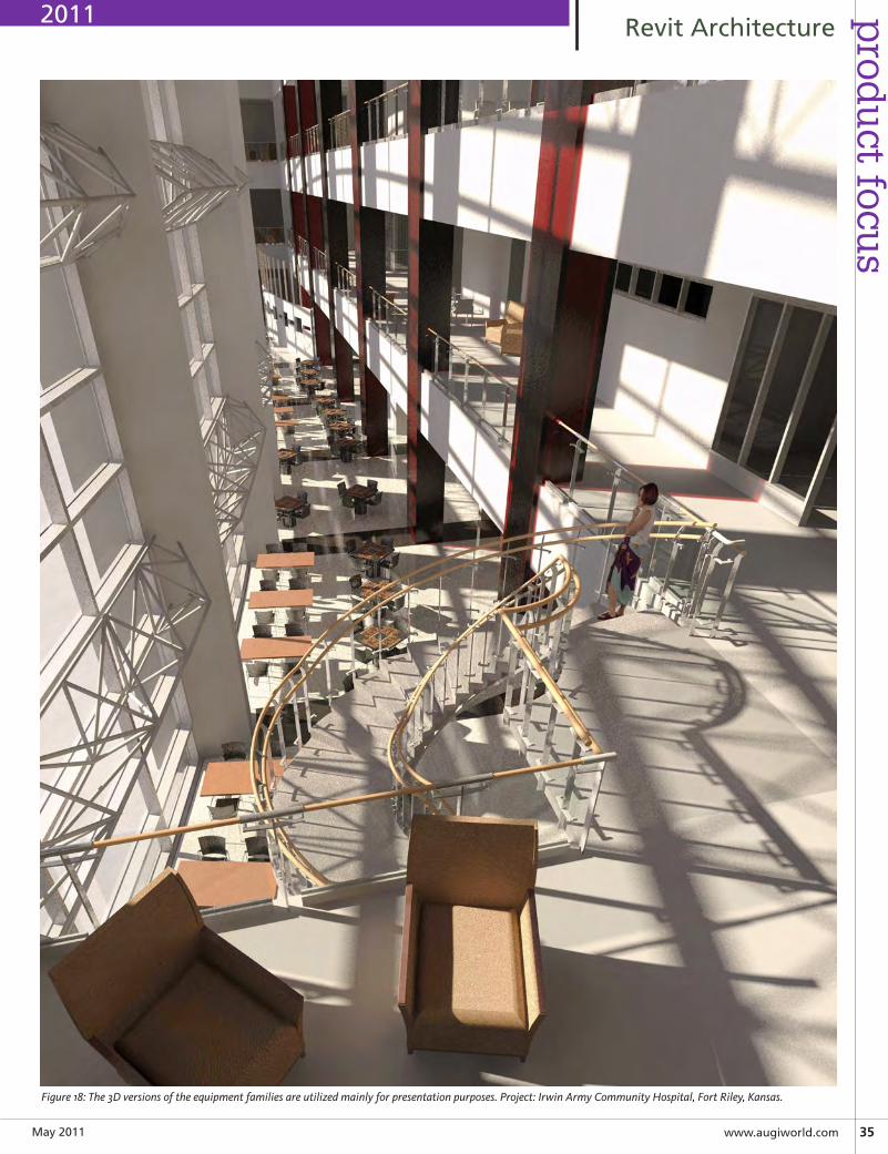
May2011 www.augiworld.com35
prod
uct focu
sRevitArchitecture
Figure 18: The 3D versions of the equipment families are utilized mainly for presentation purposes. Project: Irwin Army Community Hospital, Fort Riley, Kansas.
2011
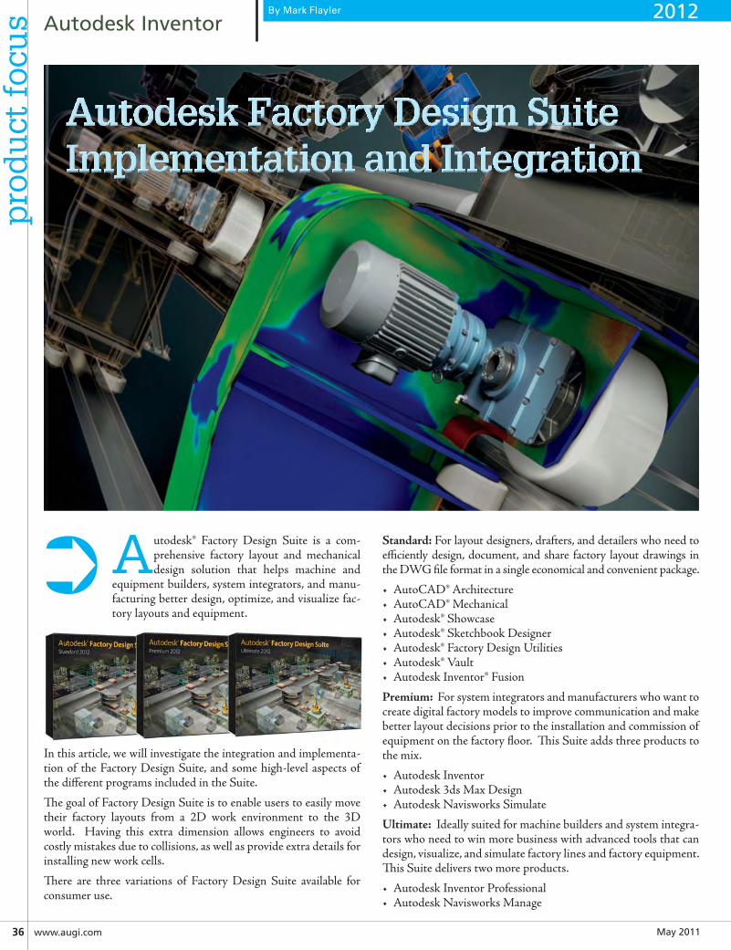
May201136 www.augi.com
pro
du
ct f
ocu
s AutodeskInventor
Autodesk® Factory Design Suite is a com-prehensive factory layout and mechanical design solution that helps machine and
equipment builders, system integrators, and manu-facturing better design, optimize, and visualize fac-tory layouts and equipment.
In this article, we will investigate the integration and implementa-tion of the Factory Design Suite, and some high-level aspects of the different programs included in the Suite.
The goal of Factory Design Suite is to enable users to easily move their factory layouts from a 2D work environment to the 3D world. Having this extra dimension allows engineers to avoid costly mistakes due to collisions, as well as provide extra details for installing new work cells.
There are three variations of Factory Design Suite available for consumer use.
Standard: For layout designers, drafters, and detailers who need to efficiently design, document, and share factory layout drawings in the DWG file format in a single economical and convenient package.
• AutoCAD® Architecture• AutoCAD® Mechanical• Autodesk® Showcase• Autodesk® Sketchbook Designer• Autodesk® Factory Design Utilities• Autodesk® Vault• Autodesk Inventor® Fusion
Premium: For system integrators and manufacturers who want to create digital factory models to improve communication and make better layout decisions prior to the installation and commission of equipment on the factory floor. This Suite adds three products to the mix.
• Autodesk Inventor• Autodesk 3ds Max Design• Autodesk Navisworks Simulate
Ultimate: Ideally suited for machine builders and system integra-tors who need to win more business with advanced tools that can design, visualize, and simulate factory lines and factory equipment. This Suite delivers two more products.
• Autodesk Inventor Professional• Autodesk Navisworks Manage
➲
By Mark Flayler
Autodesk Factory Design SuiteImplementation and Integration
2012
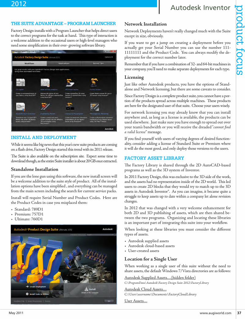
May2011 www.augiworld.com37
AutodeskInventorp
rodu
ct focus
THE SUITE ADVANTAGE – PROGRAM LAUNCHER
Factory Design installs with a Program Launcher that helps direct users to the correct programs for the task at hand. This type of interaction is a welcome addition to the occasional users or high-level managers who need some simplification in their ever- growing software library.
INSTALL AND DEPLOYMENT
While it seems like big news that this year’s new suite products are coming on a flash drive, Factory Design started this trend with its 2011 release.
The Suite is also available on the subscription site. Expect some time to download though, as the entire Suite installer is about 20 GB once extracted.
StandaloneInstallationIf you are the lone gun using this software, the new install screen will be a welcome addition to the suite style of product. All of the instal-lation options have been simplified , and everything can be managed from the main screen including the search for current service packs.
Install will require Serial Number and Product Codes. Here are the Product Codes in case you misplaced them:
• Standard: 789D1• Premium: 757D1• Ultimate: 760D1
NetworkInstallationNetwork Deployments haven’t really changed much with the Suite except in size, obviously.
If you want to get a jump on creating a deployment before you actually get your Serial Number you can use the number 111-11111111 and the Product Code. You can always modify the de-ployment for the correct number later.
Remember that if you have a combination of 32- and 64-bit machines in your company, you’ll need to make separate deployments for each type.
LicensingJust like other Autodesk products, you have the options of Stand-alone and Network licensing, but there are some caveats to consider.
Since Factory Design is a complete product suite, you cannot have a por-tion of the products spread across multiple machines. These products are here for the designated user of that suite. Choose your users wisely.
For network licensing you may already know that you can install anywhere and, as long as a license is available, the products can be used elsewhere. Just make sure you have enough to spread out over your team’s bandwidth or you will receive the dreaded “cannot find a valid license” message.
If you find yourself with users of varying degrees of desired function-ality, consider adding a license of Standard Suite or Premium where it will do the most good, and only deploy those versions to the users.
FACTORY ASSET LIBRARY
The Factory Library is shared through the 2D AutoCAD-based programs as well as the 3D system of Inventor.
In 2011 Factory Design, this was exclusive to the 3D side of the work, and the assets had no representation inside of the 2D world. This led users to create 2D blocks that they would try to match up to the 3D assets in Autodesk Inventor®. As you can imagine, it became quite a struggle to keep assets up to date within a company let alone revision changes.
In 2012 that was changed with a very welcome enhancement for both 2D and 3D publishing of assets, which are then shared be-tween the two programs. Organizing and locating these libraries is an important part of integrating this suite into your workflow.
When looking at these libraries you must consider the different types of assets.
• Autodesk supplied assets• Autodesk cloud-based assets• User-created assets
LocationforaSingleUserWhen working as a single user of this suite without the need to share assets, the default Windows 7/Vista directories are as follows:
Autodesk Supplied Assets…(hidden folder)C:\ProgramData\Autodesk\Factory Design Suite 2012\FactoryLibrary
Autodesk Cloud Assets…C:\Users\username\Documents\FactoryCloudLibrary
User Assets…
2012
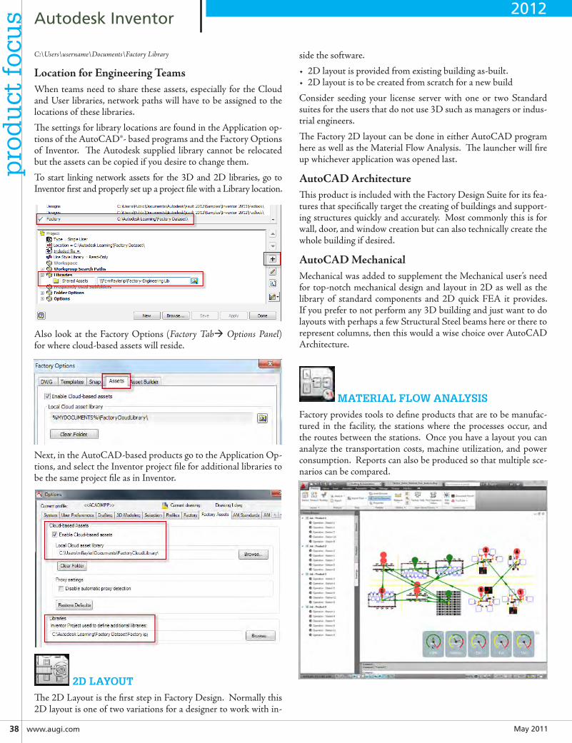
May201138 www.augi.com
AutodeskInventorp
rod
uct
foc
us
C:\Users\username\Documents\Factory Library
LocationforEngineeringTeamsWhen teams need to share these assets, especially for the Cloud and User libraries, network paths will have to be assigned to the locations of these libraries.
The settings for library locations are found in the Application op-tions of the AutoCAD®- based programs and the Factory Options of Inventor. The Autodesk supplied library cannot be relocated but the assets can be copied if you desire to change them.
To start linking network assets for the 3D and 2D libraries, go to Inventor first and properly set up a project file with a Library location.
Also look at the Factory Options (Factory Tab Options Panel) for where cloud-based assets will reside.
Next, in the AutoCAD-based products go to the Application Op-tions, and select the Inventor project file for additional libraries to be the same project file as in Inventor.
2D LAYOUT
The 2D Layout is the first step in Factory Design. Normally this 2D layout is one of two variations for a designer to work with in-
side the software.
• 2D layout is provided from existing building as-built.• 2D layout is to be created from scratch for a new build
Consider seeding your license server with one or two Standard suites for the users that do not use 3D such as managers or indus-trial engineers.
The Factory 2D layout can be done in either AutoCAD program here as well as the Material Flow Analysis. The launcher will fire up whichever application was opened last.
AutoCADArchitectureThis product is included with the Factory Design Suite for its fea-tures that specifically target the creating of buildings and support-ing structures quickly and accurately. Most commonly this is for wall, door, and window creation but can also technically create the whole building if desired.
AutoCADMechanicalMechanical was added to supplement the Mechanical user’s need for top-notch mechanical design and layout in 2D as well as the library of standard components and 2D quick FEA it provides. If you prefer to not perform any 3D building and just want to do layouts with perhaps a few Structural Steel beams here or there to represent columns, then this would a wise choice over AutoCAD Architecture.
MATERIAL FLOW ANALYSIS
Factory provides tools to define products that are to be manufac-tured in the facility, the stations where the processes occur, and the routes between the stations. Once you have a layout you can analyze the transportation costs, machine utilization, and power consumption. Reports can also be produced so that multiple sce-narios can be compared.
2012
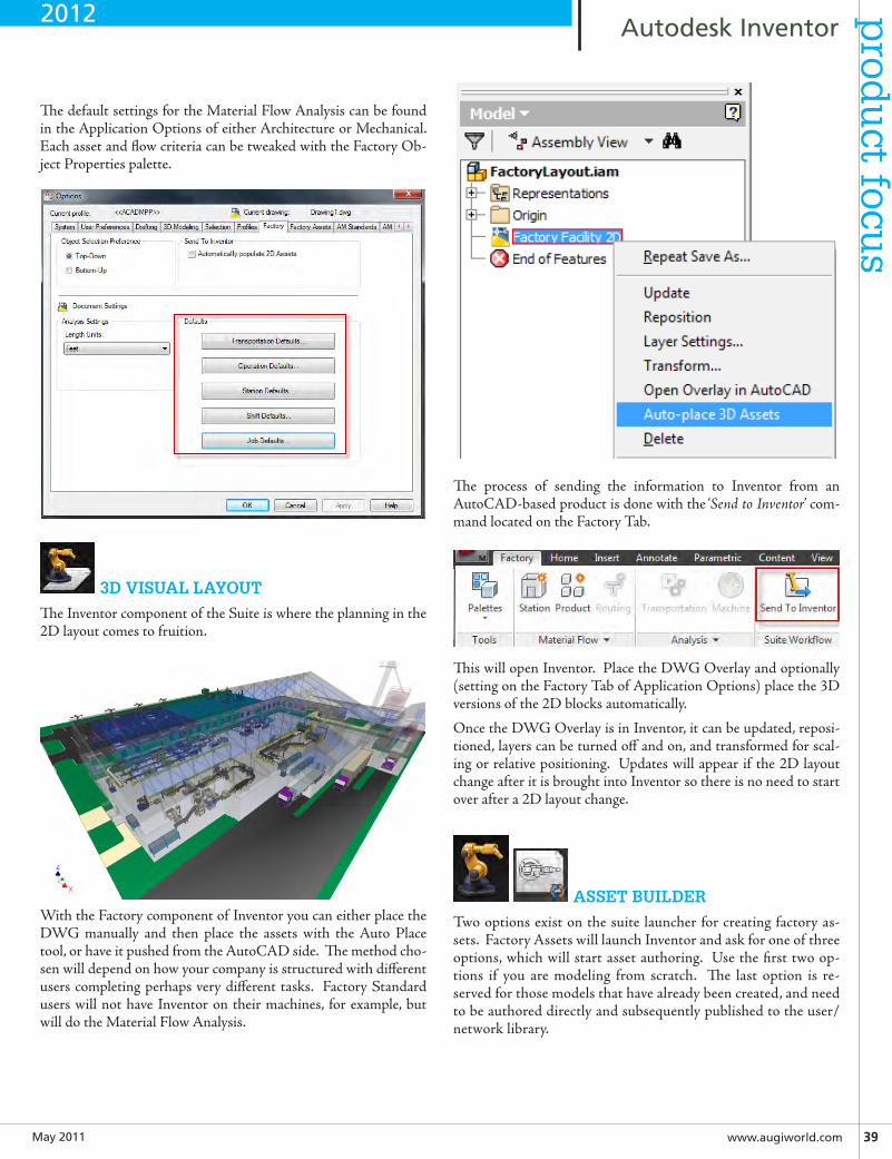
May2011 www.augiworld.com39
AutodeskInventorp
rodu
ct focus
The default settings for the Material Flow Analysis can be found in the Application Options of either Architecture or Mechanical. Each asset and flow criteria can be tweaked with the Factory Ob-ject Properties palette.
3D VISUAL LAYOUT
The Inventor component of the Suite is where the planning in the 2D layout comes to fruition.
With the Factory component of Inventor you can either place the DWG manually and then place the assets with the Auto Place tool, or have it pushed from the AutoCAD side. The method cho-sen will depend on how your company is structured with different users completing perhaps very different tasks. Factory Standard users will not have Inventor on their machines, for example, but will do the Material Flow Analysis.
The process of sending the information to Inventor from an AutoCAD-based product is done with the ‘Send to Inventor’ com-mand located on the Factory Tab.
This will open Inventor. Place the DWG Overlay and optionally (setting on the Factory Tab of Application Options) place the 3D versions of the 2D blocks automatically.
Once the DWG Overlay is in Inventor, it can be updated, reposi-tioned, layers can be turned off and on, and transformed for scal-ing or relative positioning. Updates will appear if the 2D layout change after it is brought into Inventor so there is no need to start over after a 2D layout change.
ASSET BUILDER
Two options exist on the suite launcher for creating factory as-sets. Factory Assets will launch Inventor and ask for one of three options, which will start asset authoring. Use the first two op-tions if you are modeling from scratch. The last option is re-served for those models that have already been created, and need to be authored directly and subsequently published to the user/network library.
2012
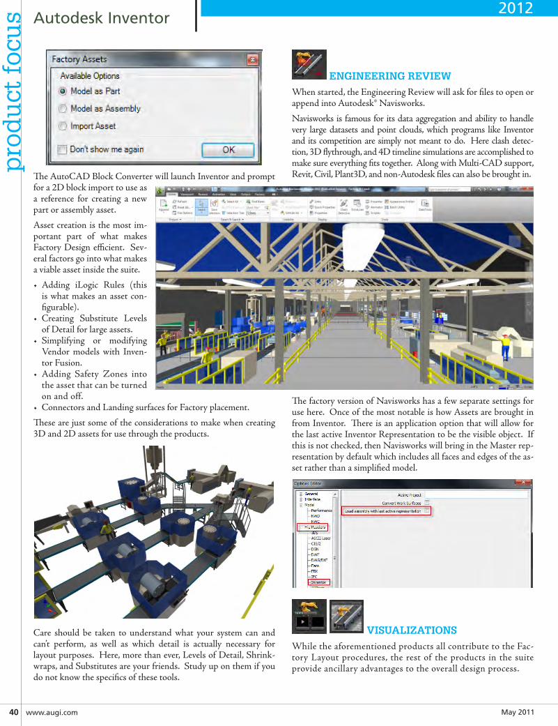
May201140 www.augi.com
AutodeskInventorp
rod
uct
foc
us
The AutoCAD Block Converter will launch Inventor and prompt for a 2D block import to use as a reference for creating a new part or assembly asset.
Asset creation is the most im-portant part of what makes Factory Design efficient. Sev-eral factors go into what makes a viable asset inside the suite.
• Adding iLogic Rules (this is what makes an asset con-figurable).
• Creating Substitute Levels of Detail for large assets.
• Simplifying or modifying Vendor models with Inven-tor Fusion.
• Adding Safety Zones into the asset that can be turned on and off.
• Connectors and Landing surfaces for Factory placement.
These are just some of the considerations to make when creating 3D and 2D assets for use through the products.
Care should be taken to understand what your system can and can’t perform, as well as which detail is actually necessary for layout purposes. Here, more than ever, Levels of Detail, Shrink-wraps, and Substitutes are your friends. Study up on them if you do not know the specifics of these tools.
ENGINEERING REVIEW
When started, the Engineering Review will ask for files to open or append into Autodesk® Navisworks.
Navisworks is famous for its data aggregation and ability to handle very large datasets and point clouds, which programs like Inventor and its competition are simply not meant to do. Here clash detec-tion, 3D flythrough, and 4D timeline simulations are accomplished to make sure everything fits together. Along with Multi-CAD support, Revit, Civil, Plant3D, and non-Autodesk files can also be brought in.
The factory version of Navisworks has a few separate settings for use here. Once of the most notable is how Assets are brought in from Inventor. There is an application option that will allow for the last active Inventor Representation to be the visible object. If this is not checked, then Navisworks will bring in the Master rep-resentation by default which includes all faces and edges of the as-set rather than a simplified model.
VISUALIZATIONS
While the aforementioned products all contribute to the Fac-tory Layout procedures, the rest of the products in the suite provide ancillary advantages to the overall design process.
2012
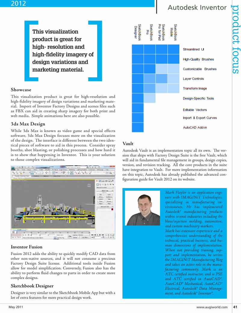
May2011 www.augiworld.com41
AutodeskInventorp
rodu
ct focus
Mark Flayler is an application engi-neer with IMAGINiT Technologies, specializing in manufacturing en-vironments. He has implemented Autodesk® manufacturing products within several industries including the blow/injection molding, automotive, and custom machinery markets. Mark has extensive experience and a comprehensive understanding of the technical, practical business, and hu-man dimensions of implementation. When not providing training, sup-port and implementation, he writes the IMAGINiT Manufacturing Blog and takes an active role in the manu-facturing community. Mark is an ATC certified instructor, and is PSE and ATC certified in AutoCAD®, AutoCAD® Mechanical, AutoCAD® Electrical, Autodesk® Data Manage-ment, and Autodesk® Inventor®.
ShowcaseThis visualization product is great for high-resolution and high-fidelity imagery of design variations and marketing mate-rial. Import of Inventor Factory Designs and scenes files such as FBX can aid in creating sharp imagery for both print and web media. Simple animations here are also possible.
3dsMaxDesignWhile 3ds Max is known as video game and special effects software, 3ds Max Design focuses more on the visualization of the design. The interface is different between the two iden-tical pieces of software to aid in this process. Consider spray booths, shot blasting, or polishing processes and how hard it is to show that happening in Inventor. This is your solution to those complex visualizations.
InventorFusionFusion 2012 adds the ability to quickly modify CAD data from other non-native sources, and it will not consume a precious Factory Design Suite license. Additional tools inside Fusion allow for model simplification. Conversely, Fusion also has the ability to perform fluid changes to parts in order to create more complex designs.
SketchbookDesignerDesigner is very similar to the Sketchbook Mobile App but with a lot of extra features for more practical design work.
VaultAutodesk Vault is an implementation topic all its own. The ver-sion that ships with Factory Design Suite is the free Vault, which will aid in fundamental file management in groups, design copies, version, and revision tracking. All the core products in the suite have integration to Vault. For more implementation information on this topic, Autodesk has already published the advanced con-figuration guide for Vault 2012 on its website.
This visualization product is great for high- resolution and high-fidelity imagery of design variations and marketing material.[ ]
2012
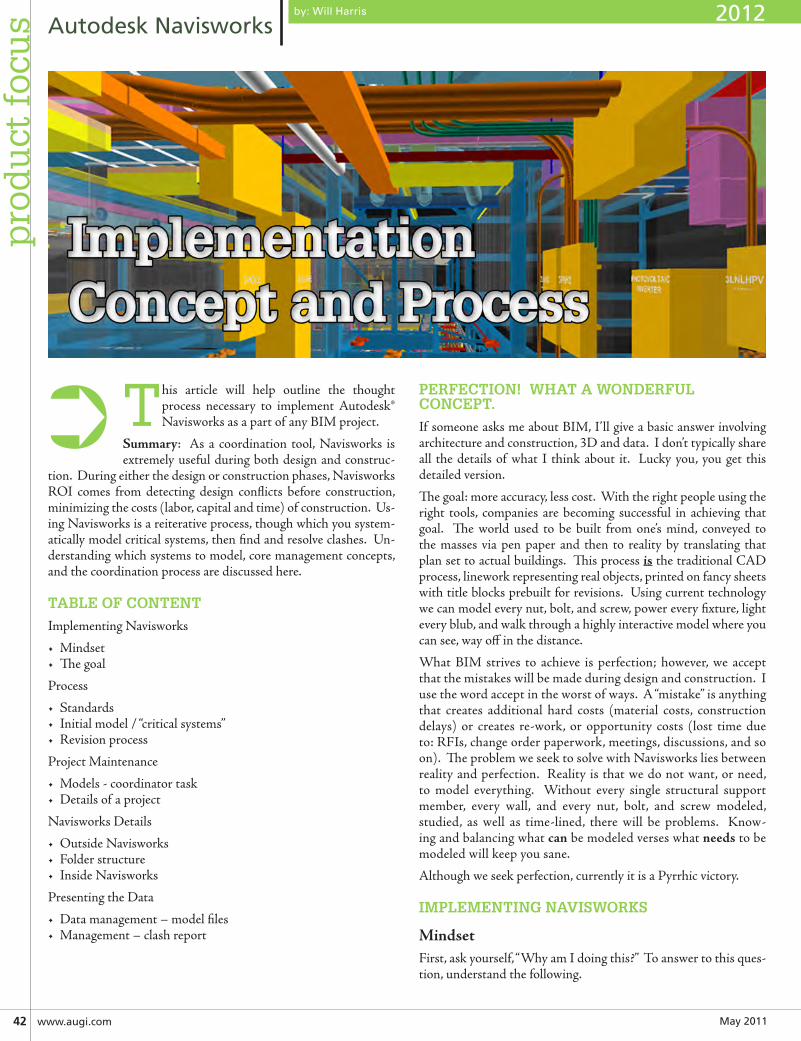
May201142 www.augi.com
pro
du
ct f
ocu
s AutodeskNavisworks
This article will help outline the thought process necessary to implement Autodesk® Navisworks as a part of any BIM project.
Summary: As a coordination tool, Navisworks is extremely useful during both design and construc-
tion. During either the design or construction phases, Navisworks ROI comes from detecting design conflicts before construction, minimizing the costs (labor, capital and time) of construction. Us-ing Navisworks is a reiterative process, though which you system-atically model critical systems, then find and resolve clashes. Un-derstanding which systems to model, core management concepts, and the coordination process are discussed here.
TABLE OF CONTENT
Implementing Navisworks
• Mindset• The goal
Process
• Standards• Initial model / “critical systems”• Revision process
Project Maintenance
• Models - coordinator task• Details of a project
Navisworks Details
• Outside Navisworks• Folder structure• Inside Navisworks
Presenting the Data
• Data management – model files• Management – clash report
PERFECTION! WHAT A WONDERFUL CONCEPT.
If someone asks me about BIM, I’ll give a basic answer involving architecture and construction, 3D and data. I don’t typically share all the details of what I think about it. Lucky you, you get this detailed version.
The goal: more accuracy, less cost. With the right people using the right tools, companies are becoming successful in achieving that goal. The world used to be built from one’s mind, conveyed to the masses via pen paper and then to reality by translating that plan set to actual buildings. This process is the traditional CAD process, linework representing real objects, printed on fancy sheets with title blocks prebuilt for revisions. Using current technology we can model every nut, bolt, and screw, power every fixture, light every blub, and walk through a highly interactive model where you can see, way off in the distance.
What BIM strives to achieve is perfection; however, we accept that the mistakes will be made during design and construction. I use the word accept in the worst of ways. A “mistake” is anything that creates additional hard costs (material costs, construction delays) or creates re-work, or opportunity costs (lost time due to: RFIs, change order paperwork, meetings, discussions, and so on). The problem we seek to solve with Navisworks lies between reality and perfection. Reality is that we do not want, or need, to model everything. Without every single structural support member, every wall, and every nut, bolt, and screw modeled, studied, as well as time-lined, there will be problems. Know-ing and balancing what can be modeled verses what needs to be modeled will keep you sane.
Although we seek perfection, currently it is a Pyrrhic victory.
IMPLEMENTING NAVISWORKS
MindsetFirst, ask yourself, “Why am I doing this?” To answer to this ques-tion, understand the following.
➲
by: Will Harris 2012
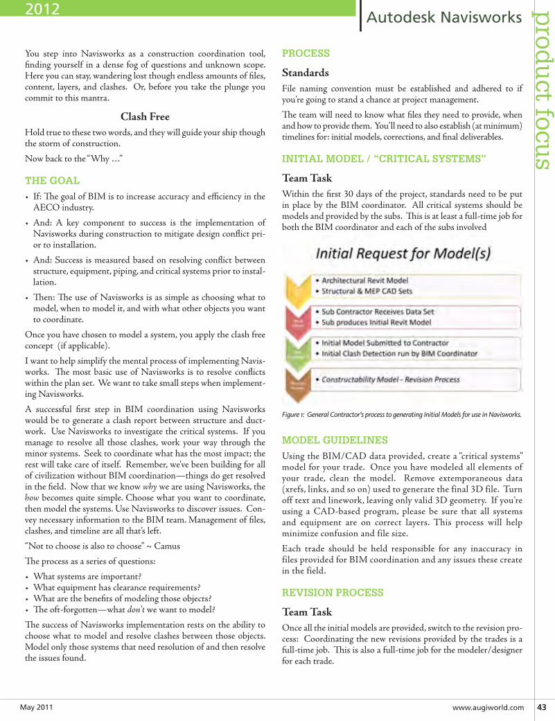
May2011 www.augiworld.com43
AutodeskNavisworksp
rodu
ct focus
You step into Navisworks as a construction coordination tool, finding yourself in a dense fog of questions and unknown scope. Here you can stay, wandering lost though endless amounts of files, content, layers, and clashes. Or, before you take the plunge you commit to this mantra.
ClashFreeHold true to these two words, and they will guide your ship though the storm of construction.
Now back to the “Why …”
THE GOAL
• If: The goal of BIM is to increase accuracy and efficiency in the AECO industry.
• And: A key component to success is the implementation of Navisworks during construction to mitigate design conflict pri-or to installation.
• And: Success is measured based on resolving conflict between structure, equipment, piping, and critical systems prior to instal-lation.
• Then: The use of Navisworks is as simple as choosing what to model, when to model it, and with what other objects you want to coordinate.
Once you have chosen to model a system, you apply the clash free concept (if applicable).
I want to help simplify the mental process of implementing Navis-works. The most basic use of Navisworks is to resolve conflicts within the plan set. We want to take small steps when implement-ing Navisworks.
A successful first step in BIM coordination using Navisworks would be to generate a clash report between structure and duct-work. Use Navisworks to investigate the critical systems. If you manage to resolve all those clashes, work your way through the minor systems. Seek to coordinate what has the most impact; the rest will take care of itself. Remember, we’ve been building for all of civilization without BIM coordination—things do get resolved in the field. Now that we know why we are using Navisworks, the how becomes quite simple. Choose what you want to coordinate, then model the systems. Use Navisworks to discover issues. Con-vey necessary information to the BIM team. Management of files, clashes, and timeline are all that’s left.
“Not to choose is also to choose” ~ Camus
The process as a series of questions:
• What systems are important?• What equipment has clearance requirements?• What are the benefits of modeling those objects?• The oft-forgotten—what don’t we want to model?
The success of Navisworks implementation rests on the ability to choose what to model and resolve clashes between those objects. Model only those systems that need resolution of and then resolve the issues found.
PROCESS
StandardsFile naming convention must be established and adhered to if you’re going to stand a chance at project management.
The team will need to know what files they need to provide, when and how to provide them. You’ll need to also establish (at minimum) timelines for: initial models, corrections, and final deliverables.
INITIAL MODEL / “CRITICAL SYSTEMS”
TeamTaskWithin the first 30 days of the project, standards need to be put in place by the BIM coordinator. All critical systems should be models and provided by the subs. This is at least a full-time job for both the BIM coordinator and each of the subs involved
Figure 1: General Contractor’s process to generating Initial Models for use in Navisworks.
MODEL GUIDELINES
Using the BIM/CAD data provided, create a “critical systems” model for your trade. Once you have modeled all elements of your trade, clean the model. Remove extemporaneous data (xrefs, links, and so on) used to generate the final 3D file. Turn off text and linework, leaving only valid 3D geometry. If you’re using a CAD-based program, please be sure that all systems and equipment are on correct layers. This process will help minimize confusion and file size.
Each trade should be held responsible for any inaccuracy in files provided for BIM coordination and any issues these create in the field.
REVISION PROCESS
TeamTaskOnce all the initial models are provided, switch to the revision pro-cess: Coordinating the new revisions provided by the trades is a full-time job. This is also a full-time job for the modeler/designer for each trade.
2012
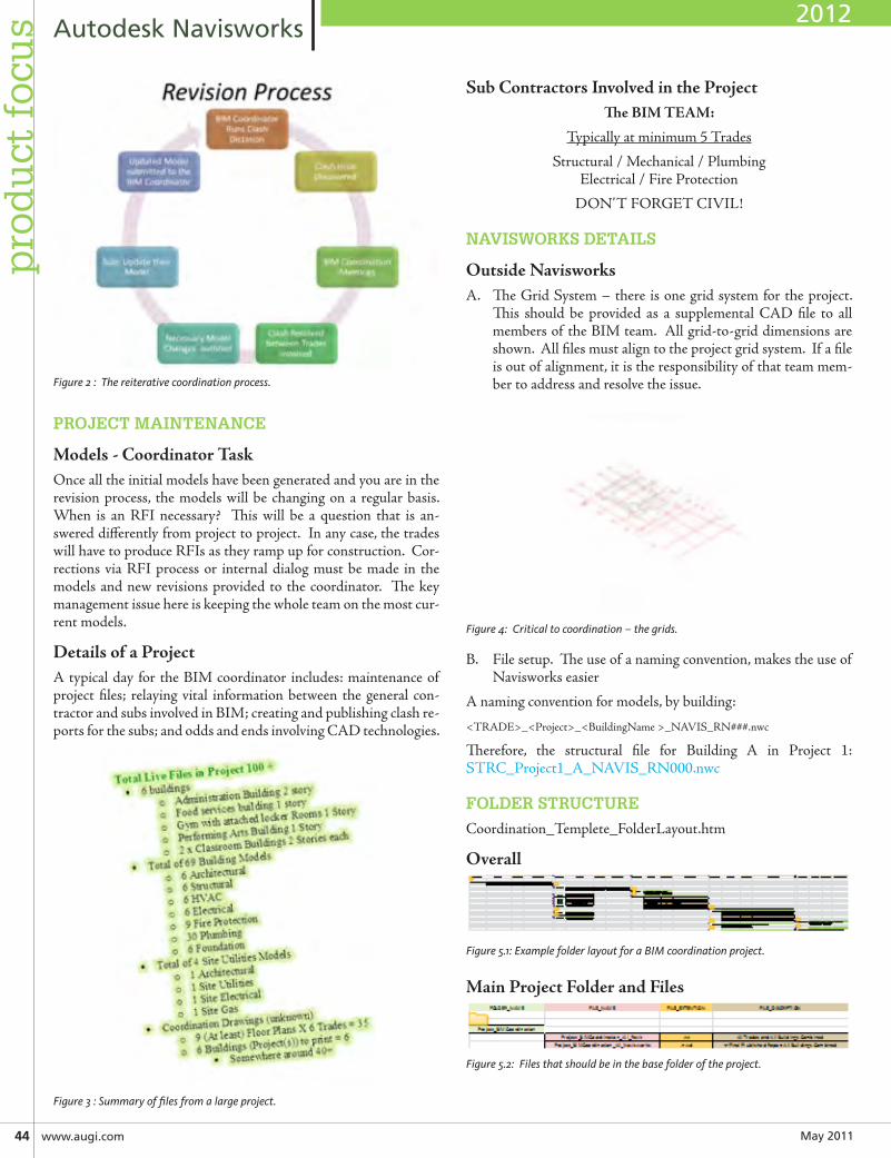
May201144 www.augi.com
AutodeskNavisworksp
rod
uct
foc
us
Figure 2 : The reiterative coordination process.
PROJECT MAINTENANCE
Models-CoordinatorTaskOnce all the initial models have been generated and you are in the revision process, the models will be changing on a regular basis. When is an RFI necessary? This will be a question that is an-swered differently from project to project. In any case, the trades will have to produce RFIs as they ramp up for construction. Cor-rections via RFI process or internal dialog must be made in the models and new revisions provided to the coordinator. The key management issue here is keeping the whole team on the most cur-rent models.
DetailsofaProjectA typical day for the BIM coordinator includes: maintenance of project files; relaying vital information between the general con-tractor and subs involved in BIM; creating and publishing clash re-ports for the subs; and odds and ends involving CAD technologies.
Figure 3 : Summary of files from a large project.
SubContractorsInvolvedintheProjectTheBIMTEAM:
Typically at minimum 5 Trades
Structural / Mechanical / Plumbing Electrical / Fire Protection
DON’T FORGET CIVIL!
NAVISWORKS DETAILS
OutsideNavisworksA. The Grid System – there is one grid system for the project.
This should be provided as a supplemental CAD file to all members of the BIM team. All grid-to-grid dimensions are shown. All files must align to the project grid system. If a file is out of alignment, it is the responsibility of that team mem-ber to address and resolve the issue.
Figure 4: Critical to coordination – the grids.
B. File setup. The use of a naming convention, makes the use of Navisworks easier
A naming convention for models, by building:
<TRADE>_<Project>_<BuildingName >_NAVIS_RN###.nwc
Therefore, the structural file for Building A in Project 1: STRC_Project1_A_NAVIS_RN000.nwc
FOLDER STRUCTURE
Coordination_Templete_FolderLayout.htm
Overall
Figure 5.1: Example folder layout for a BIM coordination project.
MainProjectFolderandFiles
Figure 5.2: Files that should be in the base folder of the project.
2012
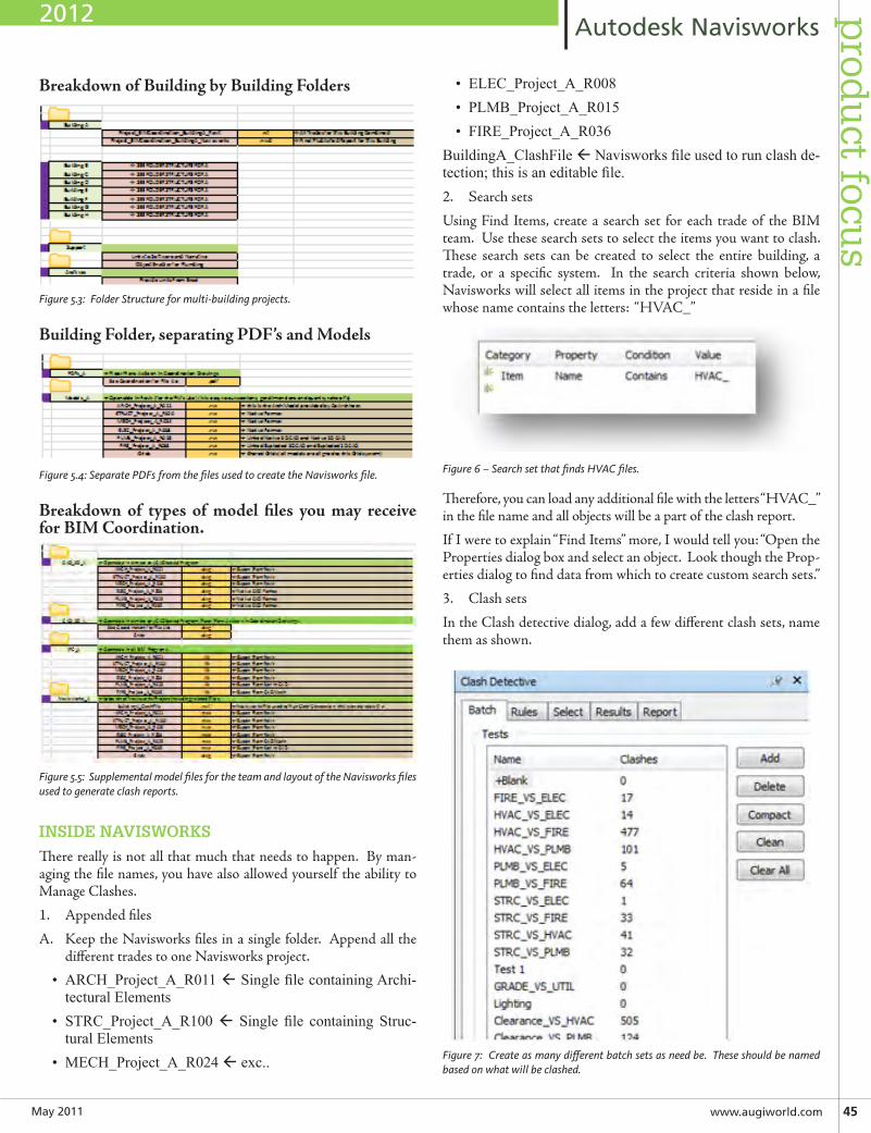
May2011 www.augiworld.com45
AutodeskNavisworksp
rodu
ct focus
BreakdownofBuildingbyBuildingFolders
Figure 5.3: Folder Structure for multi-building projects.
BuildingFolder,separatingPDF’sandModels
Figure 5.4: Separate PDFs from the files used to create the Navisworks file.
Breakdown of types of model files you may receiveforBIMCoordination.
Figure 5.5: Supplemental model files for the team and layout of the Navisworks files used to generate clash reports.
INSIDE NAVISWORKS
There really is not all that much that needs to happen. By man-aging the file names, you have also allowed yourself the ability to Manage Clashes.
1. Appended files
A. Keep the Navisworks files in a single folder. Append all the different trades to one Navisworks project.
• ARCH_Project_A_R011SinglefilecontainingArchi-tecturalElements
• STRC_Project_A_R100 Single file containing Struc-turalElements
• MECH_Project_A_R024exc..
• ELEC_Project_A_R008• PLMB_Project_A_R015• FIRE_Project_A_R036
BuildingA_ClashFileNavisworksfileusedtorunclashde-tection;thisisaneditablefile.2. Search sets
Using Find Items, create a search set for each trade of the BIM team. Use these search sets to select the items you want to clash. These search sets can be created to select the entire building, a trade, or a specific system. In the search criteria shown below, Navisworks will select all items in the project that reside in a file whose name contains the letters: “HVAC_”
Figure 6 – Search set that finds HVAC files.
Therefore, you can load any additional file with the letters “HVAC_” in the file name and all objects will be a part of the clash report.
If I were to explain “Find Items” more, I would tell you: “Open the Properties dialog box and select an object. Look though the Prop-erties dialog to find data from which to create custom search sets.”
3. Clash sets
In the Clash detective dialog, add a few different clash sets, name them as shown.
Figure 7: Create as many different batch sets as need be. These should be named based on what will be clashed.
2012
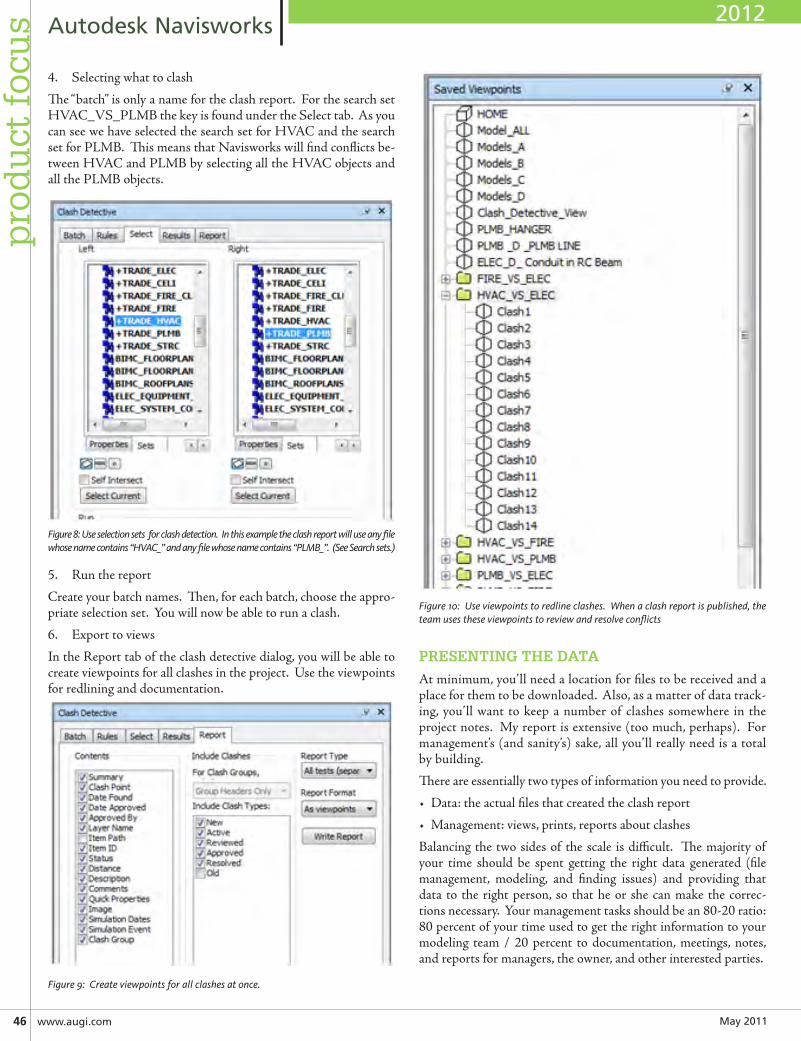
May201146 www.augi.com
AutodeskNavisworksp
rod
uct
foc
us
4. Selecting what to clash
The “batch” is only a name for the clash report. For the search set HVAC_VS_PLMB the key is found under the Select tab. As you can see we have selected the search set for HVAC and the search set for PLMB. This means that Navisworks will find conflicts be-tween HVAC and PLMB by selecting all the HVAC objects and all the PLMB objects.
Figure 8: Use selection sets for clash detection. In this example the clash report will use any file whose name contains “HVAC_” and any file whose name contains “PLMB_”. (See Search sets.)
5. Run the report
Create your batch names. Then, for each batch, choose the appro-priate selection set. You will now be able to run a clash.
6. Export to views
In the Report tab of the clash detective dialog, you will be able to create viewpoints for all clashes in the project. Use the viewpoints for redlining and documentation.
Figure 9: Create viewpoints for all clashes at once.
Figure 10: Use viewpoints to redline clashes. When a clash report is published, the team uses these viewpoints to review and resolve conflicts
PRESENTING THE DATA
At minimum, you’ll need a location for files to be received and a place for them to be downloaded. Also, as a matter of data track-ing, you’ll want to keep a number of clashes somewhere in the project notes. My report is extensive (too much, perhaps). For management’s (and sanity’s) sake, all you’ll really need is a total by building.
There are essentially two types of information you need to provide.
• Data: the actual files that created the clash report
• Management: views, prints, reports about clashes
Balancing the two sides of the scale is difficult. The majority of your time should be spent getting the right data generated (file management, modeling, and finding issues) and providing that data to the right person, so that he or she can make the correc-tions necessary. Your management tasks should be an 80-20 ratio: 80 percent of your time used to get the right information to your modeling team / 20 percent to documentation, meetings, notes, and reports for managers, the owner, and other interested parties.
2012
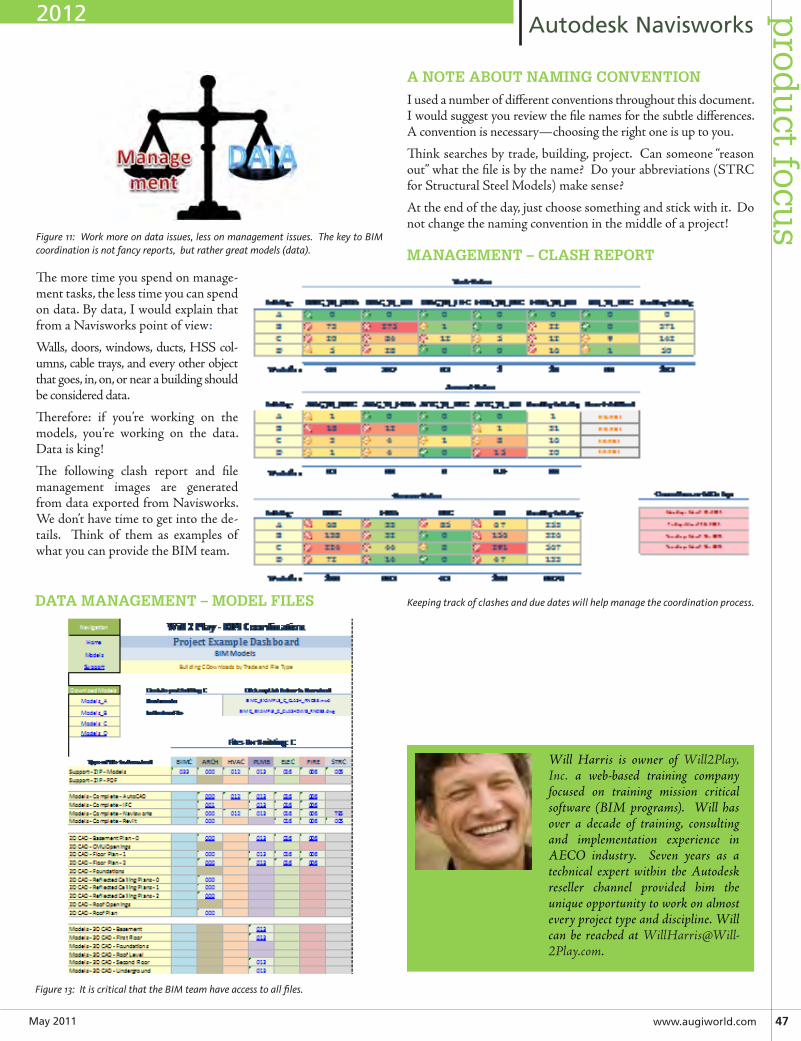
May2011 www.augiworld.com47
AutodeskNavisworksp
rodu
ct focus
Figure 11: Work more on data issues, less on management issues. The key to BIM coordination is not fancy reports, but rather great models (data).
The more time you spend on manage-ment tasks, the less time you can spend on data. By data, I would explain that from a Navisworks point of view:
Walls, doors, windows, ducts, HSS col-umns, cable trays, and every other object that goes, in, on, or near a building should be considered data.
Therefore: if you’re working on the models, you’re working on the data. Data is king!
The following clash report and file management images are generated from data exported from Navisworks. We don’t have time to get into the de-tails. Think of them as examples of what you can provide the BIM team.
A NOTE ABOUT NAMING CONVENTION
I used a number of different conventions throughout this document. I would suggest you review the file names for the subtle differences. A convention is necessary—choosing the right one is up to you.
Think searches by trade, building, project. Can someone “reason out” what the file is by the name? Do your abbreviations (STRC for Structural Steel Models) make sense?
At the end of the day, just choose something and stick with it. Do not change the naming convention in the middle of a project!
MANAGEMENT – CLASH REPORT
Keeping track of clashes and due dates will help manage the coordination process.
Will Harris is owner of Will2Play, Inc. a web-based training company focused on training mission critical software (BIM programs). Will has over a decade of training, consulting and implementation experience in AECO industry. Seven years as a technical expert within the Autodesk reseller channel provided him the unique opportunity to work on almost every project type and discipline. Will can be reached at [email protected].
Figure 13: It is critical that the BIM team have access to all files.
DATA MANAGEMENT – MODEL FILES
2012
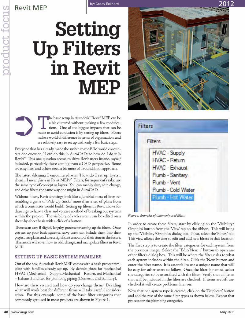
May201148 www.augi.com
RevitMEPp
rod
uct
foc
us
The basic setup in Autodesk® Revit® MEP can be a bit cluttered without making a few modifica-tions. One of the biggest impacts that can be
made to avoid confusion is by setting up filters. Filters make a world of difference in terms of organization, and are relatively easy to set up with only a few basic steps.
Everyone that has already made the switch to the BIM world encoun-ters one question, “I can do this in AutoCAD; so how do I do it in Revit?” This one question seems to drive Revit users insane, myself included, particularly those coming from a CAD perspective. Some are easy fixes and others need a bit more of a roundabout approach.
The latest dilemma I encountered was, “How do I set up layers... ahem... I mean filters in Revit MEP?” Filters, for argument’s sake, are the same type of concept as layers. You can manipulate, edit, change, and drive filters the same way one might in AutoCAD.
Without filters, Revit drawings look like a jumbled mess of lines re-sembling a game of ‘Pick-Up Sticks’ more than a set of plans from which a contractor would build. Setting up filters in Revit allows for drawings to have a clear and concise method of breaking out systems within the project. The visibility of each system can be edited on a sheet-by-sheet basis with a click of a button.
There is an easy, if slightly lengthy, process for setting up the filters. Once you set up your basic systems, savvy users can include them into their project templates and save a significant amount of their time in the future. This article will cover how to add, change, and manipulate filters in Revit MEP.
SETTING UP BASIC SYSTEM FAMILIES
Out of the box, Autodesk Revit MEP comes with a basic project tem-plate with families already set up. By default, three for mechanical HVAC (Mechanical – Supply, Mechanical – Return, and Mechanical – Exhaust) and two for plumbing piping (Domestic and Sanitary).
How are these created and how do you change them? Deciding what will work best for different firms will take careful consider-ation. For this example, some of the basic filter categories that commonly get used in most projects are shown in Figure 1.
by: Casey Eckhard
Figure 1: Examples of commonly used filters.
In order to create these filters, start by clicking on the ‘Visibility/Graphics’ button from the ‘View’ tap on the ribbon. This will bring up the ‘Visibility/Graphics’ dialog box. Next, select the ‘Filters’ tab. This view allows the user to edit and add new filters in that location.
The first step is to create the filter categories for each system from the previous image. Select the “Edit/New…” button to open an-other filter’s dialog box. This will be where the filter rules to what each system includes within the filter. Click the ‘New’ button and enter the filter name. It is essential to use a unique name that will be easy for other users to follow. Once the filter is named, select the categories to be associated with the filter. Verify that all items that will be included in the filter are checked. If items are left un-checked it will create problems later on.
Now that one system type is created, click on the ‘Duplicate’ button and add the rest of the same filter types as shown below. Repeat that process for the plumbing categories.
➲
SettingUp Filters
in Revit MEP
2012
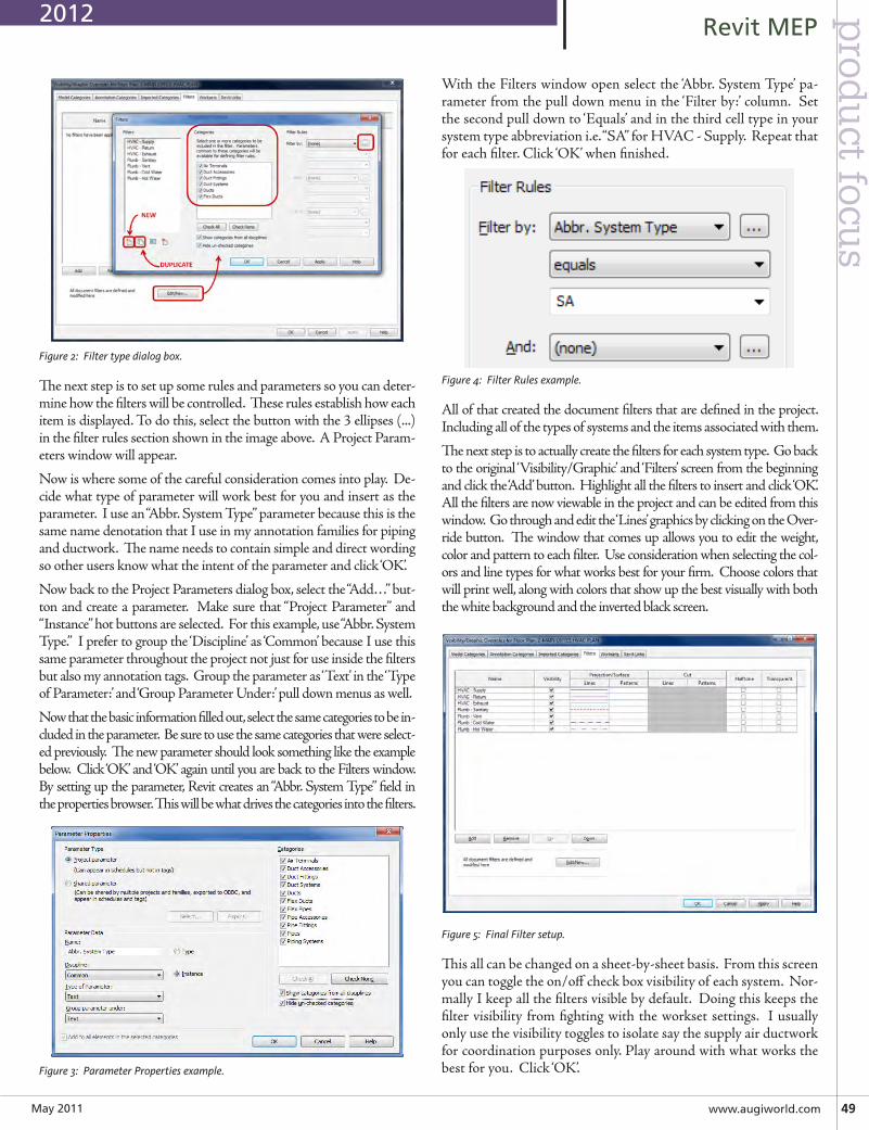
May2011 www.augiworld.com49
RevitMEPp
rodu
ct focus
Figure 2: Filter type dialog box.
The next step is to set up some rules and parameters so you can deter-mine how the filters will be controlled. These rules establish how each item is displayed. To do this, select the button with the 3 ellipses (...)in the filter rules section shown in the image above. A Project Param-eters window will appear.
Now is where some of the careful consideration comes into play. De-cide what type of parameter will work best for you and insert as the parameter. I use an “Abbr. System Type” parameter because this is the same name denotation that I use in my annotation families for piping and ductwork. The name needs to contain simple and direct wording so other users know what the intent of the parameter and click ‘OK’.
Now back to the Project Parameters dialog box, select the “Add…” but-ton and create a parameter. Make sure that “Project Parameter” and “Instance” hot buttons are selected. For this example, use “Abbr. System Type.” I prefer to group the ‘Discipline’ as ‘Common’ because I use this same parameter throughout the project not just for use inside the filters but also my annotation tags. Group the parameter as ‘Text’ in the ‘Type of Parameter:’ and ‘Group Parameter Under:’ pull down menus as well.
Now that the basic information filled out, select the same categories to be in-cluded in the parameter. Be sure to use the same categories that were select-ed previously. The new parameter should look something like the example below. Click ‘OK’ and ‘OK’ again until you are back to the Filters window. By setting up the parameter, Revit creates an “Abbr. System Type” field in the properties browser. This will be what drives the categories into the filters.
Figure 3: Parameter Properties example.
With the Filters window open select the ‘Abbr. System Type’ pa-rameter from the pull down menu in the ‘Filter by:’ column. Set the second pull down to ‘Equals’ and in the third cell type in your system type abbreviation i.e. “SA” for HVAC - Supply. Repeat that for each filter. Click ‘OK’ when finished.
Figure 4: Filter Rules example.
All of that created the document filters that are defined in the project. Including all of the types of systems and the items associated with them.
The next step is to actually create the filters for each system type. Go back to the original ‘Visibility/Graphic’ and ‘Filters’ screen from the beginning and click the ‘Add’ button. Highlight all the filters to insert and click ‘OK’. All the filters are now viewable in the project and can be edited from this window. Go through and edit the ‘Lines’ graphics by clicking on the Over-ride button. The window that comes up allows you to edit the weight, color and pattern to each filter. Use consideration when selecting the col-ors and line types for what works best for your firm. Choose colors that will print well, along with colors that show up the best visually with both the white background and the inverted black screen.
Figure 5: Final Filter setup.
This all can be changed on a sheet-by-sheet basis. From this screen you can toggle the on/off check box visibility of each system. Nor-mally I keep all the filters visible by default. Doing this keeps the filter visibility from fighting with the workset settings. I usually only use the visibility toggles to isolate say the supply air ductwork for coordination purposes only. Play around with what works the best for you. Click ‘OK’.
2012
May201150 www.augi.com
RevitMEPp
rod
uct
foc
us
Although this feels like a lot of steps, this can be included into your view template inside your initial project template to save time on future projects.
USING FILTERS INSIDE OF A PROJECT
To this point, we have created the filter types, the filter rules, the properties parameter for each filter, the actual filters, and modified how each filter will be viewed. Now is the time to control that within each project.
For this example, supply air ductwork will be used. Make sure all the windows are closed and you are back to your floor plan view. Hover your mouse over the ductwork and Tab until all of the con-necting supply ductwork is highlighted and then click your mouse. Go to the ‘Properties’ browser, scroll to the “Abbr. System Type” parameter that was created earlier. If the parameter does not ap-pear, use your ‘Filter’ button on the ribbon to remove items that were not included into the family type categories shown in the ‘Pa-rameter Properties’ and the ‘Filter’ categories from earlier. Most of the time the mechanical equipment or plumbing fixtures are what hinders the Abbr. System Type from appearing in the properties browser. If it does appear, enter “SA” for the abbreviation. For filters this is not a case-sensitive item. Repeat this step for the remaining system types and you are off and running. The final product will look similar to this (see figure).
Casey Eckhard is the BIM Manager specializing in mechanical design for the Lincoln, NE office at ME-GROUP. He can be contacted at [email protected].
2012
VisitAUGI’s
YouTube Channel
today!
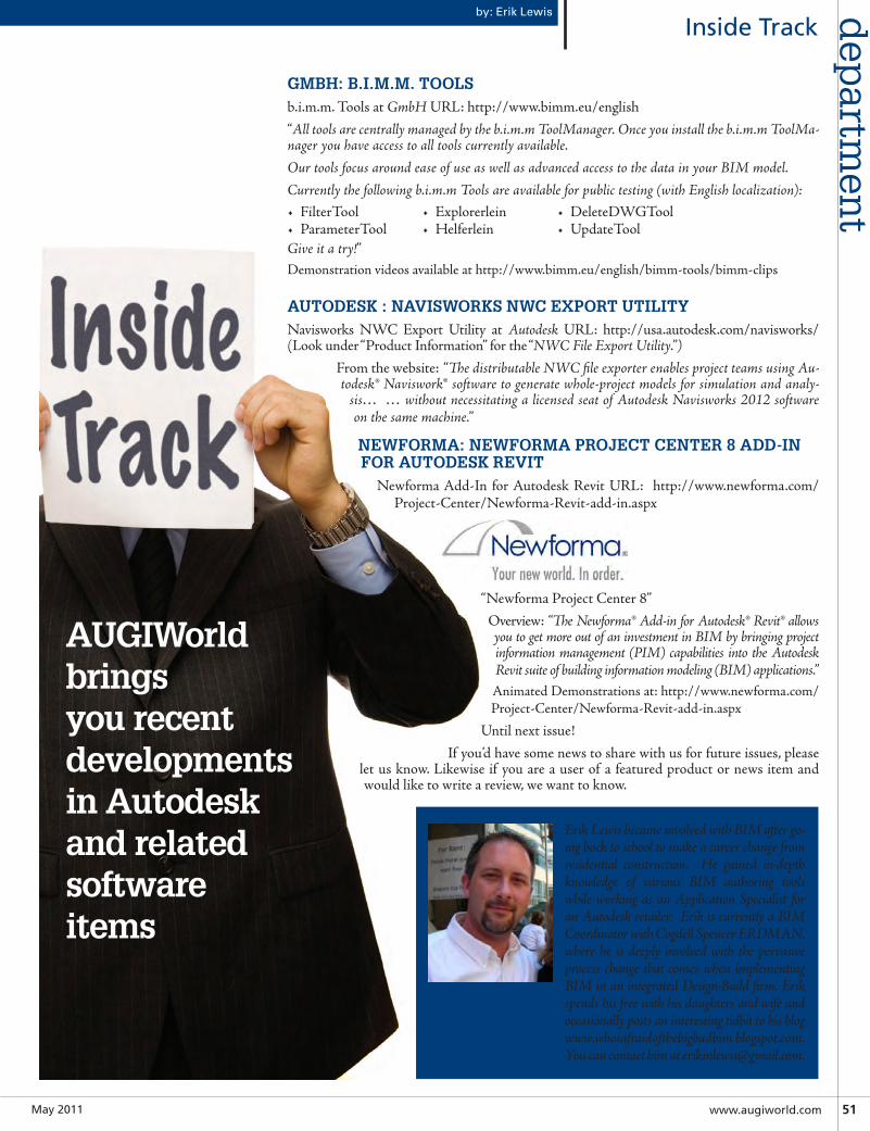
May2011 www.augiworld.com51
InsideTrackdep
artmen
tby: Erik Lewis
GMBH: B.I.M.M. TOOLSb.i.m.m. Tools at GmbH URL: http://www.bimm.eu/english
“All tools are centrally managed by the b.i.m.m ToolManager. Once you install the b.i.m.m ToolMa-nager you have access to all tools currently available.Our tools focus around ease of use as well as advanced access to the data in your BIM model.Currently the following b.i.m.m Tools are available for public testing (with English localization):• FilterTool• ParameterTool
• Explorerlein• Helferlein
• DeleteDWGTool• UpdateTool
Give it a try!”Demonstration videos available at http://www.bimm.eu/english/bimm-tools/bimm-clips
AUTODESK : NAVISWORKS NWC EXPORT UTILITYNavisworks NWC Export Utility at Autodesk URL: http://usa.autodesk.com/navisworks/ (Look under “Product Information” for the “NWC File Export Utility.”)
From the website: “The distributable NWC file exporter enables project teams using Au-todesk® Naviswork® software to generate whole-project models for simulation and analy-
sis… … without necessitating a licensed seat of Autodesk Navisworks 2012 software on the same machine.”
NEWFORMA: NEWFORMA PROJECT CENTER 8 ADD-IN FOR AUTODESK REVIT
Newforma Add-In for Autodesk Revit URL: http://www.newforma.com/Project-Center/Newforma-Revit-add-in.aspx
“Newforma Project Center 8”
Overview: “The Newforma® Add-in for Autodesk® Revit® allows you to get more out of an investment in BIM by bringing project information management (PIM) capabilities into the Autodesk Revit suite of building information modeling (BIM) applications.” Animated Demonstrations at: http://www.newforma.com/Project-Center/Newforma-Revit-add-in.aspx
Until next issue!
If you’d have some news to share with us for future issues, please let us know. Likewise if you are a user of a featured product or news item and would like to write a review, we want to know.
AUGIWorld brings you recent developments in Autodesk and related software items
Erik Lewis became involved with BIM after go-ing back to school to make a career change from residential construction. He gained in-depth knowledge of various BIM authoring tools while working as an Application Specialist for an Autodesk retailer. Erik is currently a BIM Coordinator with Cogdell Spencer ERDMAN, where he is deeply involved with the pervasive process change that comes when implementing BIM in an integrated Design-Build firm. Erik spends his free with his daughters and wife and occasionally posts an interesting tidbit to his blog www.whosafraidofthebigbadbim.blogspot.com. You can contact him at [email protected].
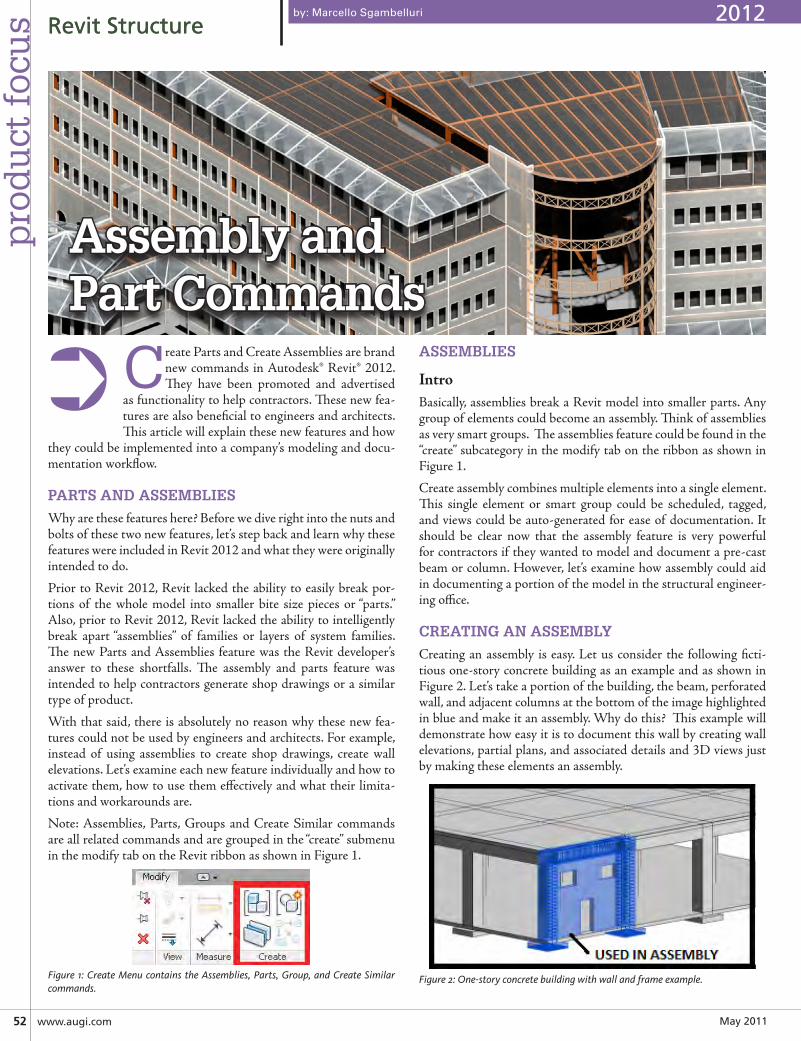
May201152 www.augi.com
pro
du
ct f
ocu
s RevitStructureRevitStructure
Create Parts and Create Assemblies are brand new commands in Autodesk® Revit® 2012. They have been promoted and advertised
as functionality to help contractors. These new fea-tures are also beneficial to engineers and architects. This article will explain these new features and how
they could be implemented into a company’s modeling and docu-mentation workflow.
PARTS AND ASSEMBLIES
Why are these features here? Before we dive right into the nuts and bolts of these two new features, let’s step back and learn why these features were included in Revit 2012 and what they were originally intended to do.
Prior to Revit 2012, Revit lacked the ability to easily break por-tions of the whole model into smaller bite size pieces or “parts.” Also, prior to Revit 2012, Revit lacked the ability to intelligently break apart “assemblies” of families or layers of system families. The new Parts and Assemblies feature was the Revit developer’s answer to these shortfalls. The assembly and parts feature was intended to help contractors generate shop drawings or a similar type of product.
With that said, there is absolutely no reason why these new fea-tures could not be used by engineers and architects. For example, instead of using assemblies to create shop drawings, create wall elevations. Let’s examine each new feature individually and how to activate them, how to use them effectively and what their limita-tions and workarounds are.
Note: Assemblies, Parts, Groups and Create Similar commands are all related commands and are grouped in the “create” submenu in the modify tab on the Revit ribbon as shown in Figure 1.
Figure 1: Create Menu contains the Assemblies, Parts, Group, and Create Similar commands.
ASSEMBLIES
IntroBasically, assemblies break a Revit model into smaller parts. Any group of elements could become an assembly. Think of assemblies as very smart groups. The assemblies feature could be found in the “create” subcategory in the modify tab on the ribbon as shown in Figure 1.
Create assembly combines multiple elements into a single element. This single element or smart group could be scheduled, tagged, and views could be auto-generated for ease of documentation. It should be clear now that the assembly feature is very powerful for contractors if they wanted to model and document a pre-cast beam or column. However, let’s examine how assembly could aid in documenting a portion of the model in the structural engineer-ing office.
CREATING AN ASSEMBLY
Creating an assembly is easy. Let us consider the following ficti-tious one-story concrete building as an example and as shown in Figure 2. Let’s take a portion of the building, the beam, perforated wall, and adjacent columns at the bottom of the image highlighted in blue and make it an assembly. Why do this? This example will demonstrate how easy it is to document this wall by creating wall elevations, partial plans, and associated details and 3D views just by making these elements an assembly.
Figure 2: One-story concrete building with wall and frame example.
by: Marcello Sgambelluri
➲
Assembly andPart Commands
2012
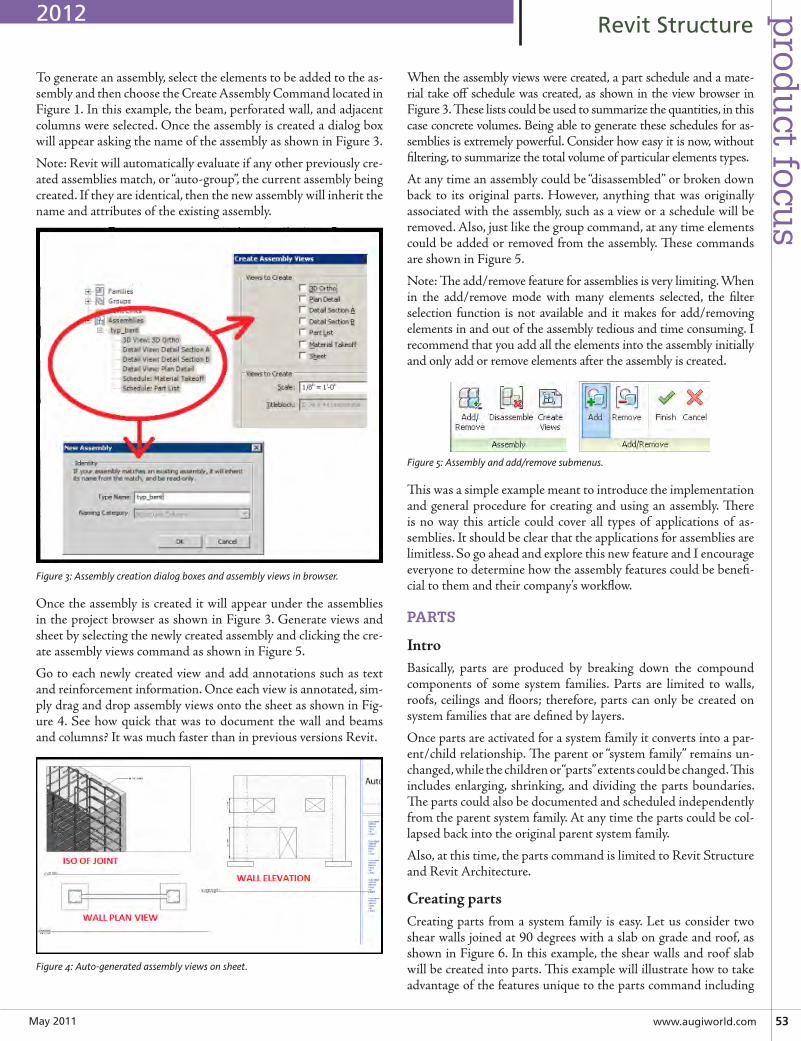
May2011 www.augiworld.com53
prod
uct focu
sRevitStructure
To generate an assembly, select the elements to be added to the as-sembly and then choose the Create Assembly Command located in Figure 1. In this example, the beam, perforated wall, and adjacent columns were selected. Once the assembly is created a dialog box will appear asking the name of the assembly as shown in Figure 3.
Note: Revit will automatically evaluate if any other previously cre-ated assemblies match, or “auto-group”, the current assembly being created. If they are identical, then the new assembly will inherit the name and attributes of the existing assembly.
Figure 3: Assembly creation dialog boxes and assembly views in browser.
Once the assembly is created it will appear under the assemblies in the project browser as shown in Figure 3. Generate views and sheet by selecting the newly created assembly and clicking the cre-ate assembly views command as shown in Figure 5.
Go to each newly created view and add annotations such as text and reinforcement information. Once each view is annotated, sim-ply drag and drop assembly views onto the sheet as shown in Fig-ure 4. See how quick that was to document the wall and beams and columns? It was much faster than in previous versions Revit.
Figure 4: Auto-generated assembly views on sheet.
When the assembly views were created, a part schedule and a mate-rial take off schedule was created, as shown in the view browser in Figure 3. These lists could be used to summarize the quantities, in this case concrete volumes. Being able to generate these schedules for as-semblies is extremely powerful. Consider how easy it is now, without filtering, to summarize the total volume of particular elements types.
At any time an assembly could be “disassembled” or broken down back to its original parts. However, anything that was originally associated with the assembly, such as a view or a schedule will be removed. Also, just like the group command, at any time elements could be added or removed from the assembly. These commands are shown in Figure 5.
Note: The add/remove feature for assemblies is very limiting. When in the add/remove mode with many elements selected, the filter selection function is not available and it makes for add/removing elements in and out of the assembly tedious and time consuming. I recommend that you add all the elements into the assembly initially and only add or remove elements after the assembly is created.
Figure 5: Assembly and add/remove submenus.
This was a simple example meant to introduce the implementation and general procedure for creating and using an assembly. There is no way this article could cover all types of applications of as-semblies. It should be clear that the applications for assemblies are limitless. So go ahead and explore this new feature and I encourage everyone to determine how the assembly features could be benefi-cial to them and their company’s workflow.
PARTS
IntroBasically, parts are produced by breaking down the compound components of some system families. Parts are limited to walls, roofs, ceilings and floors; therefore, parts can only be created on system families that are defined by layers.
Once parts are activated for a system family it converts into a par-ent/child relationship. The parent or “system family” remains un-changed, while the children or “parts” extents could be changed. This includes enlarging, shrinking, and dividing the parts boundaries.The parts could also be documented and scheduled independently from the parent system family. At any time the parts could be col-lapsed back into the original parent system family.
Also, at this time, the parts command is limited to Revit Structure and Revit Architecture.
CreatingpartsCreating parts from a system family is easy. Let us consider two shear walls joined at 90 degrees with a slab on grade and roof, as shown in Figure 6. In this example, the shear walls and roof slab will be created into parts. This example will illustrate how to take advantage of the features unique to the parts command including
2012
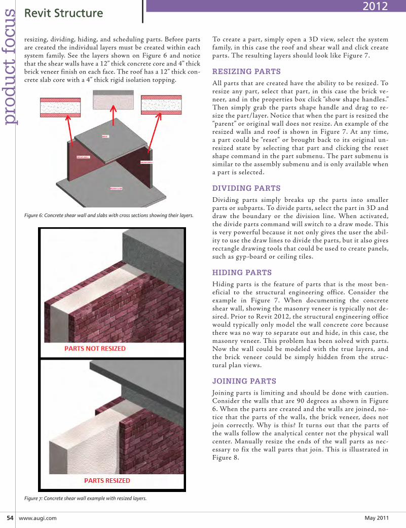
May201154 www.augi.com
pro
du
ct f
ocu
s RevitStructureRevitStructure
resizing, dividing, hiding, and scheduling parts. Before parts are created the individual layers must be created within each system family. See the layers shown on Figure 6 and notice that the shear walls have a 12” thick concrete core and 4” thick brick veneer finish on each face. The roof has a 12” thick con-crete slab core with a 4” thick rigid isolation topping.
Figure 6: Concrete shear wall and slabs with cross sections showing their layers.
Figure 7: Concrete shear wall example with resized layers.
To create a part, simply open a 3D view, select the system family, in this case the roof and shear wall and click create parts. The resulting layers should look like Figure 7.
RESIZING PARTS
All parts that are created have the ability to be resized. To resize any part, select that part, in this case the brick ve-neer, and in the properties box click “show shape handles.” Then simply grab the parts shape handle and drag to re-size the part/layer. Notice that when the part is resized the “parent” or original wall does not resize. An example of the resized walls and roof is shown in Figure 7. At any time, a part could be “reset” or brought back to its original un-resized state by selecting that part and clicking the reset shape command in the part submenu. The part submenu is similar to the assembly submenu and is only available when a part is selected.
DIVIDING PARTS
Dividing parts simply breaks up the parts into smaller parts or subparts. To divide parts, select the part in 3D and draw the boundary or the division line. When activated, the divide parts command will switch to a draw mode. This is very powerful because it not only gives the user the abil-ity to use the draw lines to divide the parts, but it also gives rectangle drawing tools that could be used to create panels, such as gyp-board or ceiling tiles.
HIDING PARTS
Hiding parts is the feature of parts that is the most ben-eficial to the structural engineering office. Consider the example in Figure 7. When documenting the concrete shear wall, showing the masonry veneer is typically not de-sired. Prior to Revit 2012, the structural engineering office would typically only model the wall concrete core because there was no way to separate out and hide, in this case, the masonry veneer. This problem has been solved with parts. Now the wall could be modeled with the true layers, and the brick veneer could be simply hidden from the struc-tural plan views.
JOINING PARTS
Joining parts is limiting and should be done with caution. Consider the walls that are 90 degrees as shown in Figure 6. When the parts are created and the walls are joined, no-tice that the parts of the walls, the brick veneer, does not join correctly. Why is this? It turns out that the parts of the walls follow the analytical center not the physical wall center. Manually resize the ends of the wall parts as nec-essary to fix the wall parts that join. This is illustrated in Figure 8.
2012
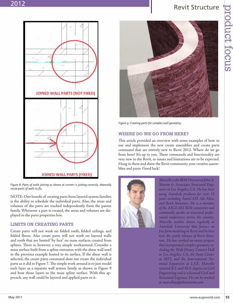
May2011 www.augiworld.com55
prod
uct focu
sRevitStructure
Figure 8: Parts of walls joining as shown at corners is joining correctly. Manually resize parts of walls to fix.
NOTE: One benefit of creating parts from layered system families is the ability to schedule the individual parts. Also, the areas and volumes of the parts are tracked independently from the parent family. Whenever a part is created, the areas and volumes are dis-played in the parts properties box.
LIMITS ON CREATING PARTS
Create parts will not work on folded roofs, folded ceilings, and folded floors. Also create parts will not work on layered walls and roofs that are hosted “by face” on mass surfaces created from splines. There is, however, a very simple workaround. Consider a mass surface built from a spline extrusion with the shear wall used in the previous example hosted to its surface. If the shear wall is selected, the create parts command does not create the individual parts as it did in Figure 7. The simple work around is to just model each layer as a separate wall system family as shown in Figure 9 and host those layers to the mass spline surface. With this ap-proach, any wall could be layered and applied parts to it.
Figure 9: Creating parts for complex wall geometry.
WHERE DO WE GO FROM HERE?
This article provided an overview with some examples of how to use and implement the new create assemblies and create parts command that are entirely new to Revit 2012. Where do we go from here? It’s up to you. These commands and functionality are very new to the Revit, so issues and limitations are to be expected. Hang in there and show the Revit community your creative assem-blies and parts. Good luck!
Marcello is the BIM Director at John A. Martin & Associates Structural Engi-neers in Los Angeles, CA. He has been using Autodesk products for over 15 years including AutoCAD, 3ds Max, and Revit Structure. He is a member of the ASCE-SEI BIM committee and continually speaks at structural profes-sional conferences across the country. Marcello teaches classes regularly at Autodesk University that focuses on free form modeling in Revit and he beta tests the yearly releases of Revit Struc-ture. He has worked on many projects that incorporated complex geometry in-cluding the Walt Disney Concert Hall in Los Angeles, CA, the Stata Center at MIT, and the International Ter-minal Expansion at LAX. Marcello received B.S. and M.S. degrees in Civil Engineering and is a licensed Civil and Structural Engineer. He can be reached at [email protected].
2012
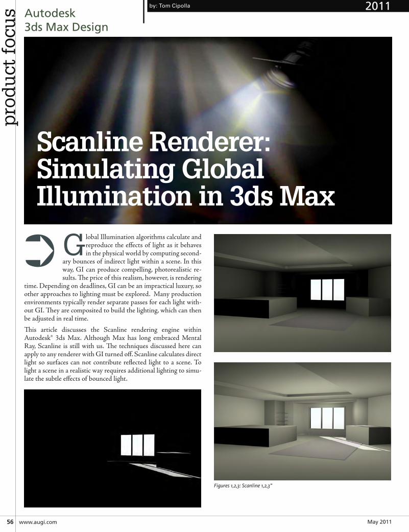
May201156 www.augi.com
pro
du
ct f
ocu
s Autodesk3dsMaxDesign
Global Illumination algorithms calculate and reproduce the effects of light as it behaves in the physical world by computing second-
ary bounces of indirect light within a scene. In this way, GI can produce compelling, photorealistic re-sults. The price of this realism, however, is rendering
time. Depending on deadlines, GI can be an impractical luxury, so other approaches to lighting must be explored. Many production environments typically render separate passes for each light with-out GI. They are composited to build the lighting, which can then be adjusted in real time.
This article discusses the Scanline rendering engine within Autodesk® 3ds Max. Although Max has long embraced Mental Ray, Scanline is still with us. The techniques discussed here can apply to any renderer with GI turned off. Scanline calculates direct light so surfaces can not contribute reflected light to a scene. To light a scene in a realistic way requires additional lighting to simu-late the subtle effects of bounced light.
Figures 1,2,3: Scanline 1,2,3”
Scanline Renderer:Simulating Global Illumination in 3ds Max
by: Tom Cipolla
➲
2011
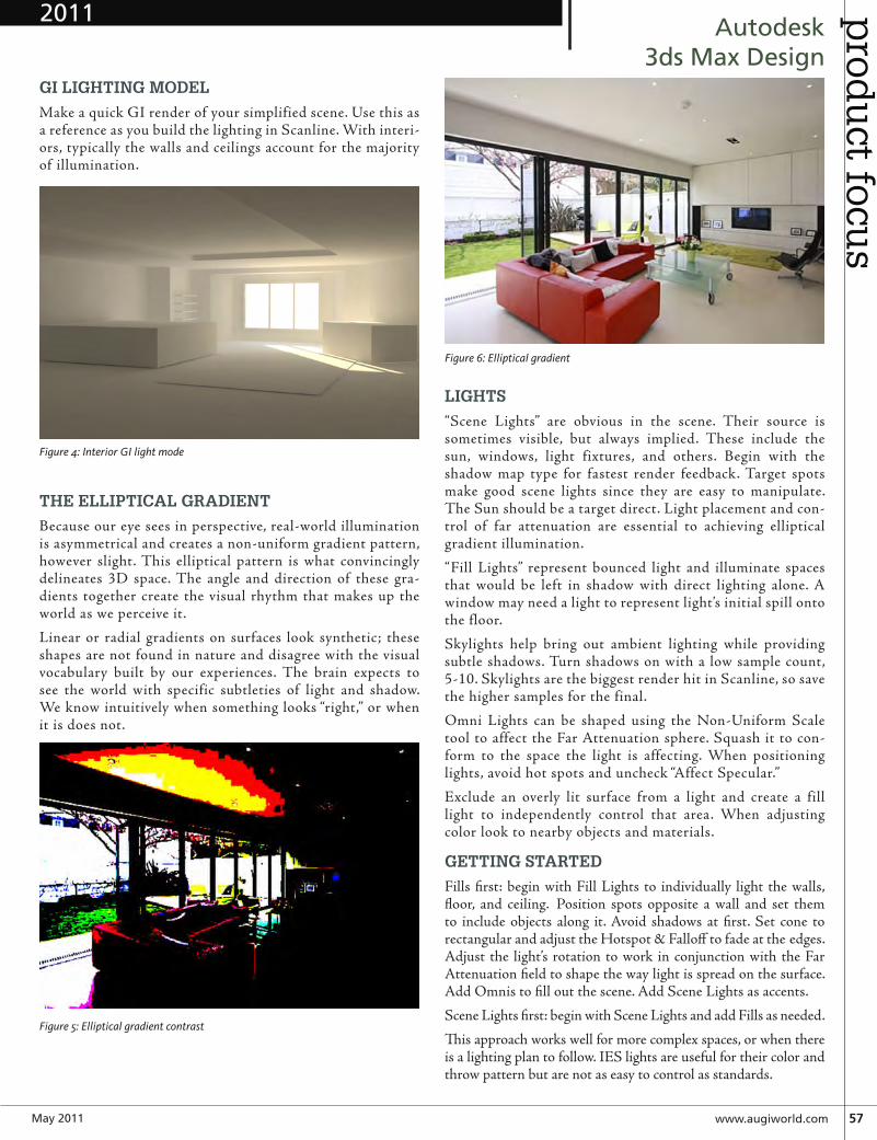
May2011 www.augiworld.com57
prod
uct focu
sAutodesk
3dsMaxDesignGI LIGHTING MODEL
Make a quick GI render of your simplified scene. Use this as a reference as you build the lighting in Scanline. With interi-ors, typically the walls and ceilings account for the majority of illumination.
Figure 4: Interior GI light mode
THE ELLIPTICAL GRADIENT
Because our eye sees in perspective, real-world illumination is asymmetrical and creates a non-uniform gradient pattern, however slight. This elliptical pattern is what convincingly delineates 3D space. The angle and direction of these gra-dients together create the visual rhythm that makes up the world as we perceive it.
Linear or radial gradients on surfaces look synthetic; these shapes are not found in nature and disagree with the visual vocabulary built by our experiences. The brain expects to see the world with specific subtleties of light and shadow. We know intuitively when something looks “right,” or when it is does not.
Figure 5: Elliptical gradient contrast
Figure 6: Elliptical gradient
LIGHTS
“Scene Lights” are obvious in the scene. Their source is sometimes visible, but always implied. These include the sun, windows, light fixtures, and others. Begin with the shadow map type for fastest render feedback. Target spots make good scene lights since they are easy to manipulate. The Sun should be a target direct. Light placement and con-trol of far attenuation are essential to achieving elliptical gradient illumination.
“Fill Lights” represent bounced light and illuminate spaces that would be left in shadow with direct lighting alone. A window may need a light to represent light’s initial spill onto the floor.
Skylights help bring out ambient lighting while providing subtle shadows. Turn shadows on with a low sample count, 5-10. Skylights are the biggest render hit in Scanline, so save the higher samples for the final.
Omni Lights can be shaped using the Non-Uniform Scale tool to affect the Far Attenuation sphere. Squash it to con-form to the space the light is affecting. When positioning lights, avoid hot spots and uncheck “Affect Specular.”
Exclude an overly lit surface from a light and create a fill light to independently control that area. When adjusting color look to nearby objects and materials.
GETTING STARTED
Fills first: begin with Fill Lights to individually light the walls, floor, and ceiling. Position spots opposite a wall and set them to include objects along it. Avoid shadows at first. Set cone to rectangular and adjust the Hotspot & Falloff to fade at the edges. Adjust the light’s rotation to work in conjunction with the Far Attenuation field to shape the way light is spread on the surface. Add Omnis to fill out the scene. Add Scene Lights as accents.
Scene Lights first: begin with Scene Lights and add Fills as needed.
This approach works well for more complex spaces, or when there is a lighting plan to follow. IES lights are useful for their color and throw pattern but are not as easy to control as standards.
2011
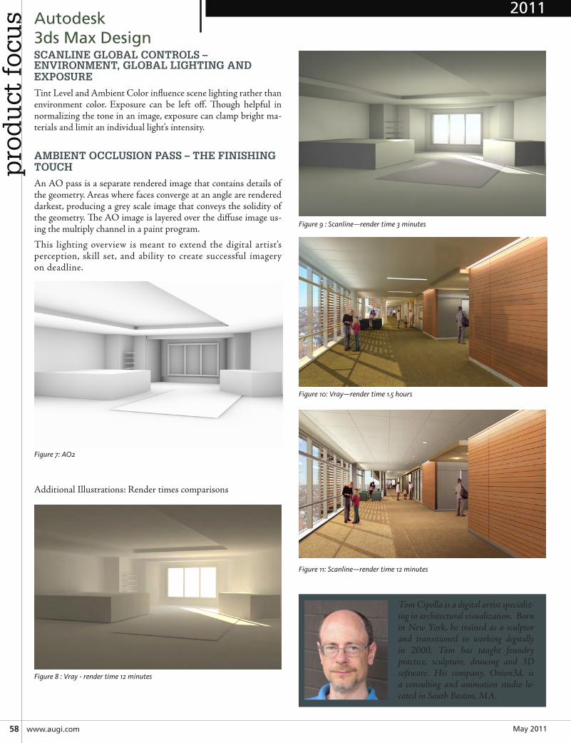
May201158 www.augi.com
pro
du
ct f
ocu
s Autodesk3dsMaxDesignSCANLINE GLOBAL CONTROLS – ENVIRONMENT, GLOBAL LIGHTING AND EXPOSURE
Tint Level and Ambient Color influence scene lighting rather than environment color. Exposure can be left off. Though helpful in normalizing the tone in an image, exposure can clamp bright ma-terials and limit an individual light’s intensity.
AMBIENT OCCLUSION PASS – THE FINISHING TOUCH
An AO pass is a separate rendered image that contains details of the geometry. Areas where faces converge at an angle are rendered darkest, producing a grey scale image that conveys the solidity of the geometry. The AO image is layered over the diffuse image us-ing the multiply channel in a paint program.
This lighting overview is meant to extend the digital artist’s perception, skill set, and ability to create successful imagery on deadline.
Figure 7: AO2
Additional Illustrations: Render times comparisons
Figure 8 : Vray - render time 12 minutes
Figure 9 : Scanline—render time 3 minutes
Figure 10: Vray—render time 1.5 hours
Figure 11: Scanline—render time 12 minutes
Tom Cipolla is a digital artist specializ-ing in architectural visualization. Born in New York, he trained as a sculptor and transitioned to working digitally in 2000. Tom has taught foundry practice, sculpture, drawing and 3D software. His company, Onion3d, is a consulting and animation studio lo-cated in South Boston, MA.
2011

dep
artmen
tHeadsUp
www.augiworld.com59May2011
by: William Troeak
HEADS UP!Updates, Service Packs and Top Known Issues obtained from product pages at Autodesk.com
AUTOCAD/ACA/AMEP
2012: SCREENMENU command is undefined by default in AutoCAD
http://usa.autodesk.com/adsk/servlet/ps/dl/item?siteID=123112&id=16927952&linkID=9240617
Standards Audit Report Hotfix for French AutoCAD 2012
http://usa.autodesk.com/adsk/servlet/ps/dl/item?siteID=123112&id=16918180&linkID=9240618
2012: AutoCAD requests to Autodesk servers blocked by proxy servers
http://usa.autodesk.com/adsk/servlet/ps/dl/item?siteID=123112&id=16732564&linkID=9240617
2012: Design Center Online is no longer a part of US English Language AutoCAD
http://usa.autodesk.com/adsk/servlet/ps/dl/item?siteID=123112&id=16927804&linkID=9240617
System Requirements for Autodesk Citrix Ready products
http://usa.autodesk.com/adsk/servlet/ps/dl/item?siteID=123112&id=16785740&linkID=9240617
AutoCAD Hardware and Network Recommendations for Citrix XenApp
http://usa.autodesk.com/adsk/servlet/ps/dl/item?siteID=123112&id=16785796&linkID=9240617
dep
artm
ent HeadsUp
May201160 www.augi.com
Autodesk 2012 Content Explorer Service Hot Fix
http://usa.autodesk.com/adsk/servlet/ps/dl/item?siteID=123112&id=16732560&linkID=9240618
CIVIL 3DTOP KNOWLEDGE BASE ISSUES
Warning message when you start AutoCAD Civil 3D or open ex-isting drawings
http://usa.autodesk.com/adsk/servlet/ps/dl/item?siteID=123112&id=14290237&linkID=9240697
Operating System Compatibility for AutoCAD Civil 3D
http://usa.autodesk.com/adsk/servlet/ps/dl/item?siteID=123112&id=15411638&linkID=9240697
AUTOCAD MAP 3D
2012: Unexpected installer launches
http://usa.autodesk.com/adsk/servlet/ps/dl/item?siteID=123112&id=16890562&linkID=9240857
Removing AutoCAD Map 3D 2012 from Window Server 2003
http://usa.autodesk.com/adsk/servlet/ps/dl/item?siteID=123112&id=16785424&linkID=9240857
Supported operating systems for AutoCAD Map 3D
http://usa.autodesk.com/adsk/servlet/ps/dl/item?siteID=123112&id=14014492&linkID=9240857
REVIT ARCHITECTURE/MEP/STRUCTURE
2012: How to Complete a Clean Install [Uninstall] of Revit products
http://usa.autodesk.com/adsk/servlet/ps/dl/item?siteID=123112&id=16828836&linkID=9243099
2012: Where to find your Autodesk Revit 2012 Product key
http://usa.autodesk.com/adsk/servlet/ps/dl/item?siteID=123112&id=16842133&linkID=9243099
Hotfix – Autodesk Revit 2011 – Error with linked model visibil-ity with custom settings
http://usa.autodesk.com/adsk/servlet/ps/dl/item?siteID=123112&id=16767377&linkID=9273944
Resetting the Autodesk Revit 2012 user interface
http://usa.autodesk.com/adsk/servlet/ps/dl/item?siteID=123112&id=16825244&linkID=9243099
Location of journal files
http://usa.autodesk.com/adsk/servlet/ps/dl/item?siteID=123112&id=9028828&linkID=9243099
Verify your driver is recommended or certified graphics hardware
http://usa.autodesk.com/adsk/servlet/ps/dl/item?siteID=123112&id=16825349&linkID=9243099
Operating system compatibility for Revit products
http://usa.autodesk.com/adsk/servlet/ps/dl/item?siteID=123112&id=14026408&linkID=9243099
System Requirements for Autodesk Revit Products
http://usa.autodesk.com/adsk/servlet/ps/dl/item?siteID=123112&id=15385625&linkID=9243099
AUTODESK INVENTOR
Inventor 2012 Readme
http://usa.autodesk.com/adsk/servlet/ps/dl/item?siteID=123112&id=15898068&linkID=9242018
Problems using iLogic in Inventor 2012
http://usa.autodesk.com/adsk/servlet/ps/dl/item?siteID=123112&id=16903013&linkID=9242018
Failed to connect solve error during Frame Analysis calculation
http://usa.autodesk.com/adsk/servlet/ps/dl/item?siteID=123112&id=16920603&linkID=9242018
Microsoft Hotfix 971138 required for Inventor to function fully with Vista operating system
http://usa.autodesk.com/adsk/servlet/ps/dl/item?siteID=123112&id=16323149&linkID=9242018
Error 1606 on Material Library installation
http://usa.autodesk.com/adsk/servlet/ps/dl/item?siteID=123112&id=16922430&linkID=9242018
Hotfix – Runner Balance in Autodesk Inventor Professional 2012 Mold Design does not work with Autodesk Moldflow Advisor 2011 or 2012
http://usa.autodesk.com/adsk/servlet/ps/dl/item?siteID=123112&id=16445311&linkID=9242019
Mold Design Desktop Content Libraries for Autodesk Inventor Professional 2012
http://usa.autodesk.com/adsk/servlet/ps/dl/item?siteID=123112&id=16264584&linkID=9242019
MOLDFLOW
Autodesk Moldflow 2012: Locating and Understanding Product Keys
http://usa.autodesk.com/adsk/servlet/ps/dl/item?siteID=123112&id=16848867&linkID=13030537
2012: Tips for Upgrading Autodesk Moldflow Products
http://usa.autodesk.com/adsk/servlet/ps/dl/item?siteID=123112&id=16849581&linkID=13030537
2012: Changing License Server Procedure
http://usa.autodesk.com/adsk/servlet/ps/dl/item?siteID=123112&id=16883419&linkID=13030537
dep
artmen
tHeadsUp
www.augiworld.com61May2011
Autodesk MoldflowInsight 2012 Hardware Certification
http://usa.autodesk.com/adsk/servlet/ps/dl/item?siteID=123112&id=16844488&linkID=13030537
3DS MAX/MAYA
Cannot load Maya 2011 or 2010 Fluids Sim with 2012 license
http://usa.autodesk.com/adsk/servlet/ps/dl/item?siteID=123112&id=16846411&linkID=9242258
MULTIPLE AUTODESK PRODUCTS
System Requirements for Autodesk Citrix Ready products
http://usa.autodesk.com/adsk/servlet/ps/dl/item?siteID=123112&id=16785740&linkID=9240617
2012: Activation and Post-Installation Tasks for Autodesk prod-ucts and suites
http://usa.autodesk.com/adsk/servlet/ps/dl/item?siteID=123112&id=16883173&linkID=9240617
Licensing and license file format for Autodesk products on Citrix XenApp
http://usa.autodesk.com/adsk/servlet/ps/dl/item?siteID=123112&id=16785782&linkID=9240617
2012: Configuring and installing Autodesk products and suites
http://usa.autodesk.com/adsk/servlet/ps/dl/item?siteID=123112&id=16854078&linkID=16831209
Failure Creating Deployment for Autodesk Building Design Suite Ultimate 2012 on Windows 7 x64 or Vista x64 Editions
http://usa.autodesk.com/adsk/servlet/ps/dl/item?siteID=123112&id=16800261&linkID=16831209
How to get Autodesk software on a CD, DVD or USB drive when you are having trouble with your download
http://usa.autodesk.com/adsk/servlet/ps/dl/item?siteID=123112&id=16845017&linkID=16831209
www.augiworld.com35April2011
HeadsUpd
epartm
ent
CIVIL 3DTop Knowledge Base Issues
System requirements for AutoCAD Civil 3Dhttp://usa.autodesk.com/adsk/servlet/ps/dl/item?siteID=123112&id=15444804&linkID=9240697
New Features Workshop for AutoCAD Civil 3D 2012http://usa.autodesk.com/civil-3d/features/
Find Graphics Hardware for Autodesk productshttp://usa.autodesk.com/adsk/servlet/cert?siteID=123112&id=16391880
REVIT ARCHITECTURE Top Knowledge Base Issues
New Features Workshop for Revit 2012http://usa.autodesk.com/revit-architecture/features/
Operating system compatibility for Revit productshttp://usa.autodesk.com/adsk/servlet/ps/dl/item?siteID=123112&id=14026408&linkID=9243099
Find Graphics Hardware for Autodesk productshttp://usa.autodesk.com/adsk/servlet/cert?siteID=123112&id=16391880
AUTODESk NAVISWORkSTop Knowledge Base Issues
System Requirements for Autodesk Navisworks 2012http://usa.autodesk.com/navisworks/system-requirements/
Operating System Compatibility for Navisworkshttp://usa.autodesk.com/adsk/servlet/ps/dl/item?siteID=123112&id=15407756&linkID=10382101
AUTODESk INVENTORTop Knowledge Base Issues
System Requirements for Inventor 2012http://usa.autodesk.com/adsk/servlet/ps/dl/item?siteID=123112&id=15402497&linkID=9242018
Microsoft hotfix 971138 required for Inventor to function fully with Vista Operating Systemshttp://usa.autodesk.com/adsk/servlet/ps/dl/item?siteID=123112&id=16323149&linkID=9242018
Operating System Compatibility table for Inventorhttp://usa.autodesk.com/adsk/servlet/ps/dl/item?siteID=123112&id=14034959&linkID=9242018
Find Graphics Hardware for Autodesk productshttp://usa.autodesk.com/adsk/servlet/cert?siteID=123112&id=16391880
LIKEfacebook.com/GoAUGI
LIKEhttp://facebook.com/GoAUGI
FOLLOW http://twitter.com/AUGIFOLLOWhttp://twitter.com/AUGI
JOINhttp://cadb.it/AUGILinkedin
JOINhttp://cadb.it/AUGILinkedin
Mr. Troeak is an Architectural Technical Specialist for U.S. CAD with over 10 years of experience in the architectural industry. Prior to joining U.S. CAD, William worked as a drafter, job captain and BIM Manager for various Architectural firms where he worked on institu-tional, commercial and residential projects. In addition, Mr. Troeak is a Revit Architecture instructor at Long Beach City College and an Autodesk Certified Professional in Revit Archi-tecture and AutoCAD. He regularly conducts seminars on the use of Au-todesk technology for Architecture and sustainable design and provides implementation, customization, train-ing, and technical support services to AEC design professionals.
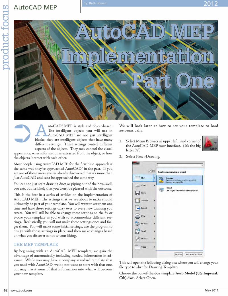
May201162 www.augi.com
AutoCADMEPp
rod
uct
foc
us
AutoCAD® MEP is style and object-based. The intelligent objects you will use in AutoCAD MEP are not just intelligent
blocks, they are intelligent objects that have many different settings. These settings control different aspects of the objects. They may control the visual
appearance, what information is extracted from the object, or how the objects interact with each other.
Most people using AutoCAD MEP for the first time approach it the same way they’ve approached AutoCAD® in the past. If you are one of those users, you’ve already discovered that it’s more than just AutoCAD and can’t be approached the same way.
You cannot just start drawing duct or piping out of the box...well, you can, but it’s likely that you won’t be pleased with the outcome.
This is the first in a series of articles on the implementation of AutoCAD MEP. The settings that we are about to make should ultimately be part of your template. You will want to set them one time and have those settings carry over to every new drawing you create. You will still be able to change these settings on the fly or evolve your template as you wish to accommodate different set-tings. Realistically, you will not make these settings once and for-get them. You will make some initial settings, use the program to design with those settings in place, and then make changes based on what you discover is not to your liking.
THE MEP TEMPLATE
By beginning with an AutoCAD MEP template, we gain the advantage of automatically including needed information in ad-vance. While you may have a company standard template that you used with AutoCAD, we do not want to start with that one, but may insert some of that information into what will become your new template.
We will look later at how to set your template to load automatically.
1. Select Menu Browser in upper left hand corner of the AutoCAD MEP user interface. (It’s the big letter “A”.)
2. Select New>Drawing.
This will open the following dialog box where you will change your file type to .dwt for Drawing Template.
Choose the out-of-the-box template AecbModel(USImperial.Ctb).dwt. Select Open.
➲
AutoCAD MEP Implementation
- Part One
by: Beth Powell 2012
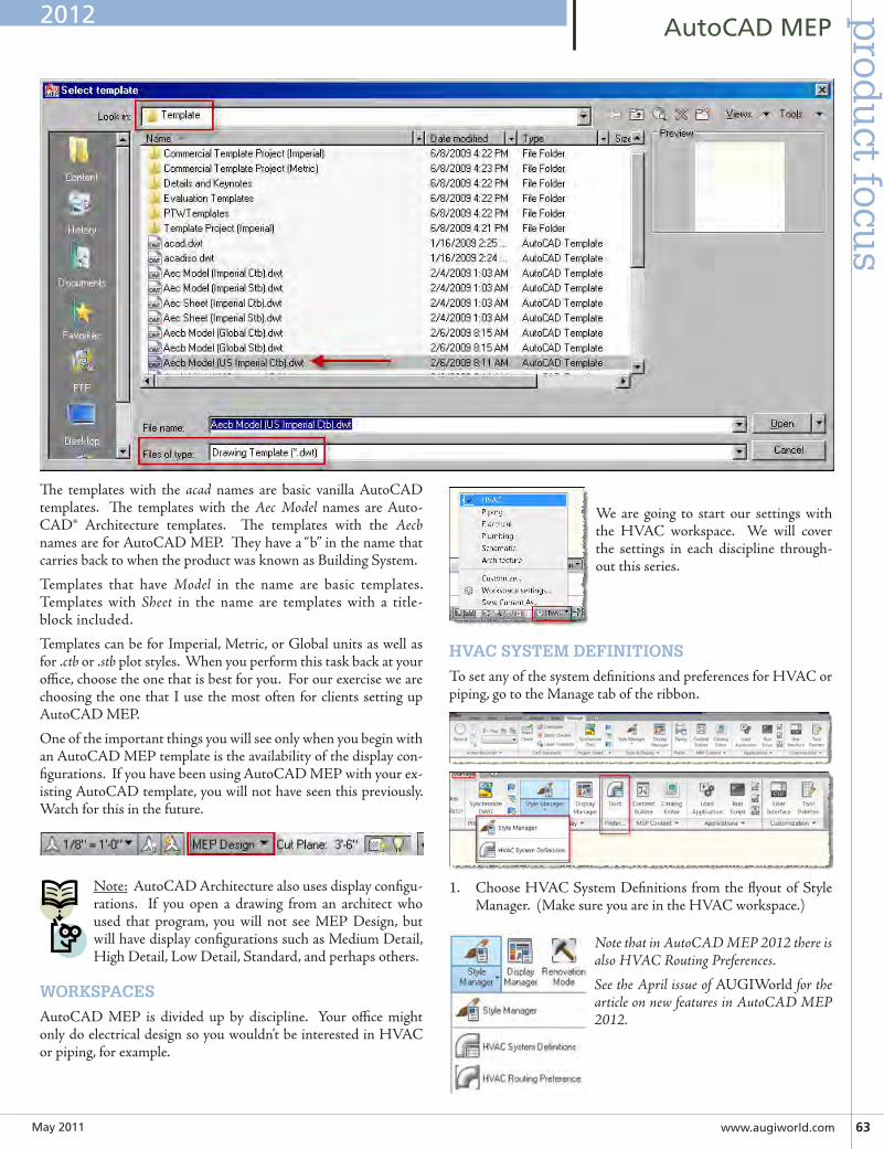
May2011 www.augiworld.com63
AutoCADMEPp
rodu
ct focus
The templates with the acad names are basic vanilla AutoCAD templates. The templates with the Aec Model names are Auto-CAD® Architecture templates. The templates with the Aecb names are for AutoCAD MEP. They have a “b” in the name that carries back to when the product was known as Building System.
Templates that have Model in the name are basic templates. Templates with Sheet in the name are templates with a title-block included.
Templates can be for Imperial, Metric, or Global units as well as for .ctb or .stb plot styles. When you perform this task back at your office, choose the one that is best for you. For our exercise we are choosing the one that I use the most often for clients setting up AutoCAD MEP.
One of the important things you will see only when you begin with an AutoCAD MEP template is the availability of the display con-figurations. If you have been using AutoCAD MEP with your ex-isting AutoCAD template, you will not have seen this previously. Watch for this in the future.
Note: AutoCAD Architecture also uses display configu-rations. If you open a drawing from an architect who used that program, you will not see MEP Design, but will have display configurations such as Medium Detail, High Detail, Low Detail, Standard, and perhaps others.
WORKSPACES
AutoCAD MEP is divided up by discipline. Your office might only do electrical design so you wouldn’t be interested in HVAC or piping, for example.
We are going to start our settings with the HVAC workspace. We will cover the settings in each discipline through-out this series.
HVAC SYSTEM DEFINITIONS
To set any of the system definitions and preferences for HVAC or piping, go to the Manage tab of the ribbon.
1. Choose HVAC System Definitions from the flyout of Style Manager. (Make sure you are in the HVAC workspace.)
Note that in AutoCAD MEP 2012 there is also HVAC Routing Preferences.
See the April issue of AUGIWorld for the article on new features in AutoCAD MEP 2012.
2012
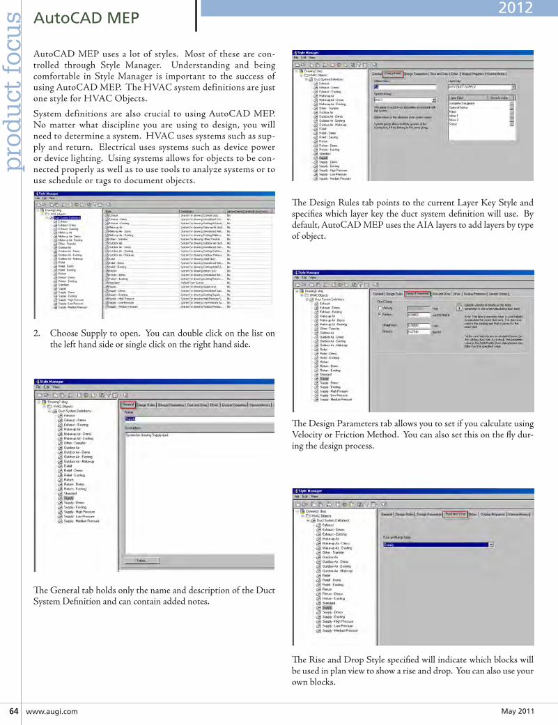
May201164 www.augi.com
AutoCADMEPp
rod
uct
foc
us
The Design Rules tab points to the current Layer Key Style and specifies which layer key the duct system definition will use. By default, AutoCAD MEP uses the AIA layers to add layers by type of object.
The Design Parameters tab allows you to set if you calculate using Velocity or Friction Method. You can also set this on the fly dur-ing the design process.
The Rise and Drop Style specified will indicate which blocks will be used in plan view to show a rise and drop. You can also use your own blocks.
AutoCAD MEP uses a lot of styles. Most of these are con-trolled through Style Manager. Understanding and being comfortable in Style Manager is important to the success of using AutoCAD MEP. The HVAC system definitions are just one style for HVAC Objects.
System definitions are also crucial to using AutoCAD MEP. No matter what discipline you are using to design, you will need to determine a system. HVAC uses systems such as sup-ply and return. Electrical uses systems such as device power or device lighting. Using systems allows for objects to be con-nected properly as well as to use tools to analyze systems or to use schedule or tags to document objects.
2. Choose Supply to open. You can double click on the list on the left hand side or single click on the right hand side.
The General tab holds only the name and description of the Duct System Definition and can contain added notes.
2012
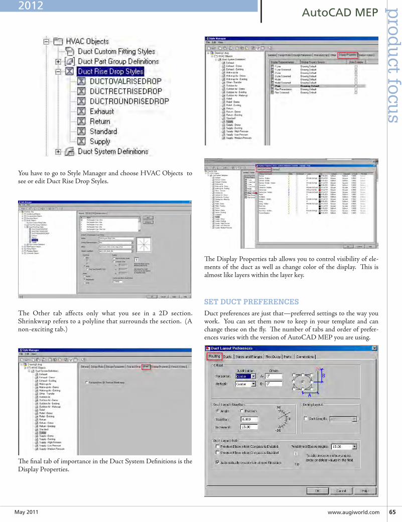
May2011 www.augiworld.com65
AutoCADMEPp
rodu
ct focus
You have to go to Style Manager and choose HVAC Objects to see or edit Duct Rise Drop Styles.
The Other tab affects only what you see in a 2D section. Shrinkwrap refers to a polyline that surrounds the section. (A non-exciting tab.)
The final tab of importance in the Duct System Definitions is the Display Properties.
The Display Properties tab allows you to control visibility of ele-ments of the duct as well as change color of the display. This is almost like layers within the layer key.
SET DUCT PREFERENCES
Duct preferences are just that—preferred settings to the way you work. You can set them now to keep in your template and can change these on the fly. The number of tabs and order of prefer-ences varies with the version of AutoCAD MEP you are using.
2012
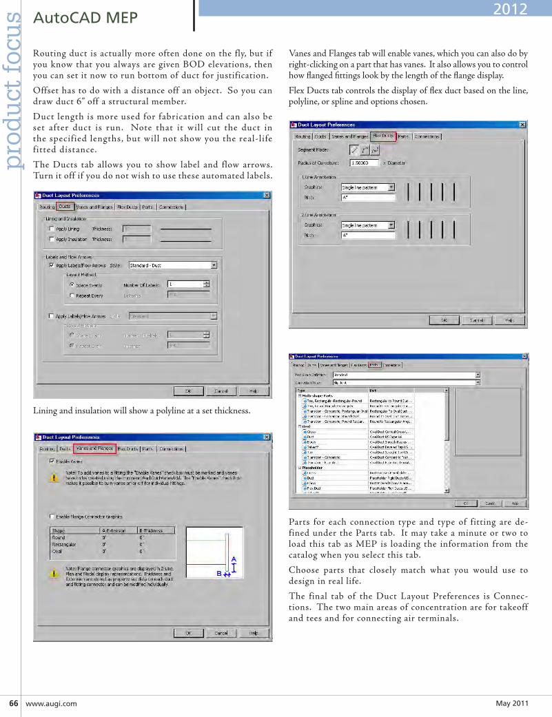
May201166 www.augi.com
AutoCADMEPp
rod
uct
foc
us
Routing duct is actually more often done on the fly, but if you know that you always are given BOD elevations, then you can set it now to run bottom of duct for justification.
Offset has to do with a distance off an object. So you can draw duct 6” off a structural member.
Duct length is more used for fabrication and can also be set after duct is run. Note that it will cut the duct in the specified lengths, but will not show you the real-life fitted distance.
The Ducts tab allows you to show label and flow arrows. Turn it off if you do not wish to use these automated labels.
Lining and insulation will show a polyline at a set thickness.
Vanes and Flanges tab will enable vanes, which you can also do by right-clicking on a part that has vanes. It also allows you to control how flanged fittings look by the length of the flange display.
Flex Ducts tab controls the display of flex duct based on the line, polyline, or spline and options chosen.
Parts for each connection type and type of fitting are de-fined under the Parts tab. It may take a minute or two to load this tab as MEP is loading the information from the catalog when you select this tab.
Choose parts that closely match what you would use to design in real life.
The final tab of the Duct Layout Preferences is Connec-tions. The two main areas of concentration are for takeoff and tees and for connecting air terminals.
2012
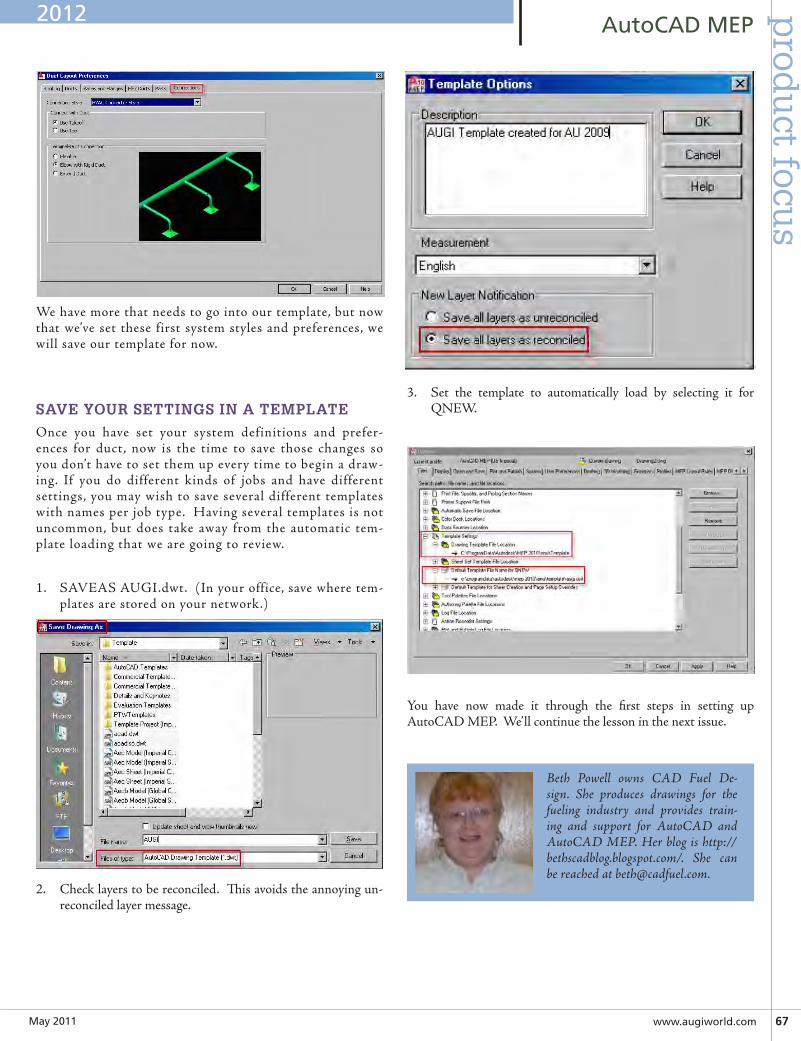
May2011 www.augiworld.com67
AutoCADMEPp
rodu
ct focus
We have more that needs to go into our template, but now that we’ve set these first system styles and preferences, we will save our template for now.
SAVE YOUR SETTINGS IN A TEMPLATE
Once you have set your system definitions and prefer-ences for duct, now is the time to save those changes so you don’t have to set them up every time to begin a draw-ing. If you do different kinds of jobs and have different settings, you may wish to save several different templates with names per job type. Having several templates is not uncommon, but does take away from the automatic tem-plate loading that we are going to review.
1. SAVEAS AUGI.dwt. (In your office, save where tem-plates are stored on your network.)
2. Check layers to be reconciled. This avoids the annoying un-reconciled layer message.
3. Set the template to automatically load by selecting it for QNEW.
You have now made it through the first steps in setting up AutoCAD MEP. We’ll continue the lesson in the next issue.
Beth Powell owns CAD Fuel De-sign. She produces drawings for the fueling industry and provides train-ing and support for AutoCAD and AutoCAD MEP. Her blog is http://bethscadblog.blogspot.com/. She can be reached at [email protected].
2012
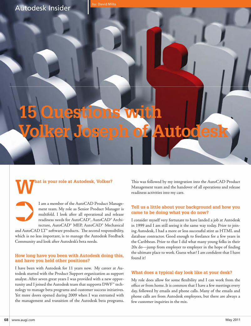
May201168 www.augi.com
AutodeskInsider
What is your role at Autodesk, Volker?
I am a member of the AutoCAD Product Manage-ment team. My role as Senior Product Manager is multifold. I look after all operational and release readiness needs for AutoCAD®, AutoCAD® Archi-tecture, AutoCAD® MEP, AutoCAD® Mechanical
and AutoCAD LT® software products. The second responsibility, which is no less important, is to manage the Autodesk Feedback Community and look after Autodesk’s beta needs.
How long have you been with Autodesk doing this, and have you held other positions?
I have been with Autodesk for 11 years now. My career at Au-todesk started with the Product Support organization as support analyst. After seven great years I was provided with a new oppor-tunity and I joined the Autodesk team that supports DWF™ tech-nology to manage beta programs and customer success initiatives. Yet more doors opened during 2009 when I was entrusted with the management and transition of the Autodesk beta programs.
15 Questions withVolker Joseph of Autodesk
by: David Mills
This was followed by my integration into the AutoCAD Product Management team and the handover of all operations and release readiness activities into my care.
Tell us a little about your background and how you came to be doing what you do now?
I consider myself very fortunate to have landed a job at Autodesk in 1999 and I am still seeing it the same way today. Prior to join-ing Autodesk, I had a more or less successful stint as HTML and database contractor. Good enough to freelance for a few years in the Caribbean. Prior to that I did what many young folks in their 20s do—jump from employer to employer in the hope of finding the ultimate place to work. Guess what? I am confident that I have found it!
What does a typical day look like at your desk?
My role does allow for some flexibility and I can work from the office or from home. It is common that I have a few meetings every day, followed by emails and phone calls. Many of the emails and phone calls are from Autodesk employees, but there are always a few customer inquiries in the mix.
➲
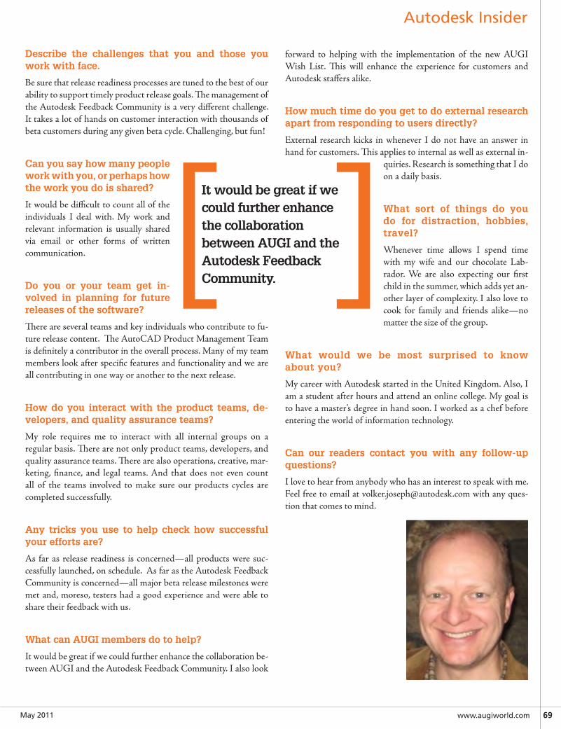
May2011 www.augiworld.com69
AutodeskInsider
Describe the challenges that you and those you work with face.
Be sure that release readiness processes are tuned to the best of our ability to support timely product release goals. The management of the Autodesk Feedback Community is a very different challenge. It takes a lot of hands on customer interaction with thousands of beta customers during any given beta cycle. Challenging, but fun!
Can you say how many people work with you, or perhaps how the work you do is shared?
It would be difficult to count all of the individuals I deal with. My work and relevant information is usually shared via email or other forms of written communication.
Do you or your team get in-volved in planning for future releases of the software?
There are several teams and key individuals who contribute to fu-ture release content. The AutoCAD Product Management Team is definitely a contributor in the overall process. Many of my team members look after specific features and functionality and we are all contributing in one way or another to the next release.
How do you interact with the product teams, de-velopers, and quality assurance teams?
My role requires me to interact with all internal groups on a regular basis. There are not only product teams, developers, and quality assurance teams. There are also operations, creative, mar-keting, finance, and legal teams. And that does not even count all of the teams involved to make sure our products cycles are completed successfully.
Any tricks you use to help check how successful your efforts are?
As far as release readiness is concerned—all products were suc-cessfully launched, on schedule. As far as the Autodesk Feedback Community is concerned—all major beta release milestones were met and, moreso, testers had a good experience and were able to share their feedback with us.
What can AUGI members do to help?
It would be great if we could further enhance the collaboration be-tween AUGI and the Autodesk Feedback Community. I also look
forward to helping with the implementation of the new AUGI Wish List. This will enhance the experience for customers and Autodesk staffers alike.
How much time do you get to do external research apart from responding to users directly?
External research kicks in whenever I do not have an answer in hand for customers. This applies to internal as well as external in-
quiries. Research is something that I do on a daily basis.
What sort of things do you do for distraction, hobbies, travel?
Whenever time allows I spend time with my wife and our chocolate Lab-rador. We are also expecting our first child in the summer, which adds yet an-other layer of complexity. I also love to cook for family and friends alike—no matter the size of the group.
What would we be most surprised to know about you?
My career with Autodesk started in the United Kingdom. Also, I am a student after hours and attend an online college. My goal is to have a master’s degree in hand soon. I worked as a chef before entering the world of information technology.
Can our readers contact you with any follow-up questions?
I love to hear from anybody who has an interest to speak with me. Feel free to email at [email protected] with any ques-tion that comes to mind.
[ ]It would be great if we could further enhance the collaboration between AUGI and the Autodesk Feedback Community.
AUGI, through the contributions
of members, produces monthly magazines such as AUGIWorld. Well the articles in these magazines don’t grow on trees! The content comes from members willing to contribute. If you are an AUGI member, you probably use an Autodesk product. Do you know your product pretty well? Have you ever sat down with someone else to explain how Paper Space works, or how to explode polylines, or customize the CUI? These messages you share casually with others are the same messages that others outside of your area need to hear. Just imagine… even though you have been using AutoCAD since R9, today, somewhere in the world, someone started using AutoCAD for the first time. And that expert level change you made to your CUI to work better with your PGP today? Tomorrow someone else will
If you’ve visited www.AUGI.com recently, then you’ve seen a highly visible
improvement in AUGI’s member interface. But one of the most exciting features is still flying under the radar and that is the Library. The Library is the home for articles and
whitepapers that the membership contribute to the organization. There is a tremendous amount of material
generated by members and until now that content ‘shelf life’ was pretty short. Since magazines
come out monthly, an article’s time in the spotlight is brief. Well, no longer! As issues of AUGIWorld,
AUGI | AEC EDGE are replaced by new ones, the staff at AUGI will be posting article content on the website in HTML. The magazine PDFs will stay, of course. Consider the AUGI Library a new area to read some great content. Finding articles from past issues is a breeze, because searching and categorization can now be applied to these articles. In addition, the Library is the real home for AUGI HotNews, an email-based monthly publication.
Been to the Library?
Are you ready
to write?
begin that exercise as well and you could save them some time with your insight. So, get out there and join the fun – contribute to your magazines and your fellow members. Share your knowledge and expertise with beginners and advanced users alike. People are ready to hear what you have to say. For more details contact [email protected]