Embed Size (px)
Citation preview
Dialogic® Digital Network Interface Software Reference
Copyright © 1999-2008 Dialogic Corporation
05-1313-006
Copyright and Legal Notice
Copyright © 1999-2008 Dialogic Corporation. All Rights Reserved. You may not reproduce this document in whole or in part without permission in writing from Dialogic Corporation at the address provided below.
All contents of this document are furnished for informational use only and are subject to change without notice and do not represent a commitment on the part of Dialogic Corporation or its subsidiaries (“Dialogic”). Reasonable effort is made to ensure the accuracy of the information contained in the document. However, Dialogic does not warrant the accuracy of this information and cannot accept responsibility for errors, inaccuracies, or omissions that may be contained in this document.
INFORMATION IN THIS DOCUMENT IS PROVIDED IN CONNECTION WITH DIALOGIC® PRODUCTS. NO LICENSE, EXPRESS OR IMPLIED, BY ESTOPPEL OR OTHERWISE, TO ANY INTELLECTUAL PROPERTY RIGHTS IS GRANTED BY THIS DOCUMENT. EXCEPT AS PROVIDED IN A SIGNED AGREEMENT BETWEEN YOU AND DIALOGIC, DIALOGIC ASSUMES NO LIABILITY WHATSOEVER, AND DIALOGIC DISCLAIMS ANY EXPRESS OR IMPLIED WARRANTY, RELATING TO SALE AND/OR USE OF DIALOGIC PRODUCTS INCLUDING LIABILITY OR WARRANTIES RELATING TO FITNESS FOR A PARTICULAR PURPOSE, MERCHANTABILITY, OR INFRINGEMENT OF ANY INTELLECTUAL PROPERTY RIGHT OF A THIRD PARTY.
Dialogic products are not intended for use in medical, life saving, life sustaining, critical control or safety systems, or in nuclear facility applications.
Due to differing national regulations and approval requirements, certain Dialogic products may be suitable for use only in specific countries, and thus may not function properly in other countries. You are responsible for ensuring that your use of such products occurs only in the countries where such use is suitable. For information on specific products, contact Dialogic Corporation at the address indicated below or on the web at www.dialogic.com.
It is possible that the use or implementation of any one of the concepts, applications, or ideas described in this document, in marketing collateral produced by or on web pages maintained by Dialogic may infringe one or more patents or other intellectual property rights owned by third parties. Dialogic does not provide any intellectual property licenses with the sale of Dialogic products other than a license to use such product in accordance with intellectual property owned or validly licensed by Dialogic and no such licenses are provided except pursuant to a signed agreement with Dialogic. More detailed information about such intellectual property is available from Dialogic’s legal department at 9800 Cavendish Blvd., 5th Floor, Montreal, Quebec, Canada H4M 2V9. Dialogic encourages all users of its products to procure all necessary intellectual property licenses required to implement any concepts or applications and does not condone or encourage any intellectual property infringement and disclaims any responsibility related thereto. These intellectual property licenses may differ from country to country and it is the responsibility of those who develop the concepts or applications to be aware of and comply with different national license requirements.
Dialogic, Dialogic Pro, Brooktrout, Cantata, SnowShore, Eicon, Eicon Networks, Eiconcard, Diva, SIPcontrol, Diva ISDN, TruFax, Realblocs, Realcomm 100, NetAccess, Instant ISDN, TRXStream, Exnet, Exnet Connect, EXS, ExchangePlus VSE, Switchkit, N20, Powering The Service-Ready Network, Vantage, Making Innovation Thrive, Connecting People to Information, Connecting to Growth and Shiva, among others as well as related logos, are either registered trademarks or trademarks of Dialogic Corporation or its subsidiaries. Dialogic's trademarks may be used publicly only with permission from Dialogic. Such permission may only be granted by Dialogic’s legal department at 9800 Cavendish Blvd., 5th Floor, Montreal, Quebec, Canada H4M 2V9. Any authorized use of Dialogic's trademarks will be subject to full respect of the trademark guidelines published by Dialogic from time to time and any use of Dialogic’s trademarks requires proper acknowledgement.
Windows is a registered trademark of Microsoft Corporation in the United States and/or other countries. Other names of actual companies and product mentioned herein are the trademarks of their respective owners.
Publication Date: December 2008
Document Number: 05-1313-006
2
Table of Contents 1. How to Use This Manual .............................................................................. 11 1.1. Getting Started with This Guide .................................................................. 11 1.2. Organization of this Guide........................................................................... 12 2. General Description ...................................................................................... 13 2.1. Typical Applications .................................................................................... 13 2.2. Compatibility................................................................................................ 14 2.3. SCbus Overview .......................................................................................... 15 3. Digital Telephony Overview......................................................................... 17 3.1. T1 Digital Telephony ................................................................................... 17
3.1.1. T1 Frame Format................................................................................. 17 3.1.2. T1 Synchronization ............................................................................. 19 3.1.3. T1 Signaling ........................................................................................ 19
3.2. E1 Digital Telephony ................................................................................... 20 3.2.1. E1 Frame Format................................................................................. 20 3.2.2. E1 Synchronization ............................................................................. 22 3.2.3. E1 Signaling ........................................................................................ 23 3.2.4. E1 National and International Bits ...................................................... 25
3.3. Digital Network Interface Hardware Implementation.................................. 26 3.3.1. SCbus Routing..................................................................................... 26 3.3.2. Loss of Synchronization Alarm Handling........................................... 26 3.3.3. Digital Network Interface Hardware Alarm Indicators ....................... 30
4. Function Overview........................................................................................ 31 4.1. Dialogic® Digital Network Interface API Library Function Categories ...... 31
4.1.1. Alarm Functions .................................................................................. 32 4.1.2. Diagnostic Functions........................................................................... 32 4.1.3. Extended Attribute Functions.............................................................. 32 4.1.4. Parameter Request Functions .............................................................. 33 4.1.5. Parameter Setting Functions................................................................ 33 4.1.6. Resource Management Functions........................................................ 33 4.1.7. Routing Functions ............................................................................... 34 4.1.8. Statistics Functions.............................................................................. 34 4.1.9. Time Slot Audio Functions ................................................................. 34 4.1.10. Time Slot Signaling Functions .......................................................... 35
4.2. Error Handling ............................................................................................. 36 4.3. Include Files................................................................................................. 39
3
Dialogic® Digital Network Interface Software Reference
5. Function Reference ....................................................................................... 41 ATDT_BDMODE( ) - returns the current mode of every time slot..................... 42 ATDT_BDSGBIT( ) - returns the current state of the transmit and receive bits . 45 ATDT_DNLDVER( ) - returns the firmware version.......................................... 49 ATDT_IDLEST( ) - returns the current idle state................................................ 54 ATDT_ROMVER( ) - returns the version of the EPROM .................................. 57 ATDT_STATUS( ) - returns the current status.................................................... 62 ATDT_TSMODE( ) - returns the current signaling mode................................... 65 ATDT_TSSGBIT( ) - retrieves the current bit state ............................................ 68 dt_castdecode( ) - decode the CAS DTI reply or event message block ............... 71 dt_castencode( ) - validate and encode the message ............................................ 73 dt_castmgmt( ) - manage the CAS DTI templates ............................................... 75 dt_close( ) - closes digital network interface devices .......................................... 87 dt_dial( ) - allows the application to pulse dial .................................................... 89 dt_getctinfo( ) - returns information about the digital network interface............. 94 dt_getevt( ) - blocks and returns control to the program...................................... 98 dt_getevtmsk( ) - retrieves the current event bitmask(s) .................................... 102 dt_getparm( ) - gets the current parameter value ............................................... 107 dt_getstatistics( ) - returns the statistics queried ................................................ 114 dt_getxmitslot( ) - returns the SCbus time slot................................................... 119 dt_listen( ) - connects the digital listen channel ................................................. 122 dt_open( ) - opens a digital network interface device ........................................ 126 dt_rundiag( ) - runs diagnostics ......................................................................... 129 dt_setalrm( ) - sets the alarm handling mode ..................................................... 134 dt_setevtmsk( ) - enables and disables notification for events ........................... 137 dt_setidle( ) - enables or disables transmission.................................................. 143 dt_setparm( ) - changes the value of a DNI device parameter ........................... 146 dt_setsigmod( ) - sets the type of signaling........................................................ 149 dt_settssig( ) - sets or clears the transmit ........................................................... 152 dt_settssigsim( ) - simultaneous setting or clearing of transmit signaling bits... 155 dt_tstcom( ) - tests the ability of a digital network interface device .................. 158 dt_tstdat( ) - performs a test ............................................................................... 162 dt_unlisten( ) - disconnects the receive channel................................................. 166 dt_xmitalrm( ) - starts and stops transmission of an alarm ................................ 169 dt_xmitwink( ) - transmits wink signaling ......................................................... 172 6. Application Guidelines................................................................................ 177 6.1. Writing a Simple Application .................................................................... 177
6.1.1. General Guidelines ............................................................................ 177 6.1.2. Initialization....................................................................................... 180
4
Table of Contents
6.1.3. Processing.......................................................................................... 185 6.1.4. Terminating ....................................................................................... 190 6.1.5. Compiling and Linking ..................................................................... 192 6.1.6. Aborting ............................................................................................ 192
6.2. Adding Advanced Features........................................................................ 192 7. Dialogic® Digital Network Interface API for Dialogic® DM3 Boards .... 195 7.1. Digital Network Interface API Function Restrictions................................ 195 7.2. Detecting Layer 1 Alarms .......................................................................... 196 Appendix A – Dialogic® Standard Runtime Library .................................... 199 Digital Network Interface Entries and Returns .................................................. 199 Event Management Functions............................................................................ 200 Standard Attribute Functions ............................................................................. 203 TPT Structure..................................................................................................... 205 Appendix B - Message Blocks ......................................................................... 207 Command Message Blocks ................................................................................ 207 Reply Message Blocks ....................................................................................... 225 Unsolicited Events ............................................................................................. 235 Appendix C - dticas.h Header File.................................................................. 237 Appendix D - Related Publications................................................................. 243 Glossary ............................................................................................................ 245 Index.................................................................................................................. 251
5

Dialogic® Digital Network Interface Software Reference
6
List of Tables Table 1. Error Types Defined in dtilib.h ............................................................. 37 Table 2. ATDT_DNLDVER( ) Return Values ................................................... 51 Table 3. ATDT_ROMVER( ) Return Values ..................................................... 59 Table 4. Common Data Types............................................................................. 77 Table 5. dt_getevtmsk( ) Return Values............................................................ 103 Table 6. dt_getparm( ) Parameters .................................................................... 107 Table 7. Recommended dt_setalrm( ) Settings ................................................. 181 Table 8. List of Dialogic® Digital Network Interface API Functions
Supported on Dialogic® DM3 boards........................................................ 196 Table 9. Guide to Appendix A .......................................................................... 199 Table 10. Digital Network Interface Inputs for Event Management Functions 201 Table 11. Digital Network Interface Returns from Event Management
Functions ................................................................................................... 203 Table 12. Standard Attribute Functions ............................................................ 204 Table 13. DV_TPT Structure ............................................................................ 205
7

Dialogic® Digital Network Interface Software Reference
8
List of Figures Figure 1. D4 Frame Format................................................................................. 18 Figure 2. D4 Superframe Format ........................................................................ 19 Figure 3. E1 Frame Format ................................................................................. 21 Figure 4. E1 Multiframe Format ......................................................................... 21 Figure 5. Individual Frame Synchronization....................................................... 22 Figure 6. Multiframe Synchronization ................................................................ 23 Figure 7. Channel Associated Signaling (CAS) Protocol ................................... 24 Figure 8. E1 National and International Bits....................................................... 26 Figure 9. T1 Alarm Conditions ........................................................................... 28 Figure 10. E1 Loss of Synchronization Alarm Requirements............................. 29 Figure 11. Firmware Version Number Format.................................................... 50 Figure 12. EPROM Version Number Format ..................................................... 58 Figure 13. Transition Timing, Receive ............................................................. 208 Figure 14. Transition Timing, Transmit............................................................ 208 Figure 15. Pulse Timing, Receive ..................................................................... 211 Figure 16. Pulse Timing, Transmit.................................................................... 211 Figure 17. Pulse Train Timing, Receive ........................................................... 214 Figure 18. Pulse Train Timing, Transmit .......................................................... 214
9

Dialogic® Digital Network Interface Software Reference
10
1. How to Use This Manual
This guide is for users who have a Dialogic® Digital Network Interface or Voice and Network Board and related software installed on a host computer operating in a Linux or Windows® environment.
For a list of the hardware products supported with this software, see the Release Guide for your Dialogic® Software Release.
1.1. Getting Started with This Guide
The following steps explain the order in which a Dialogic® Digital Network Interface Board and related software products should be installed, checked, and programmed.
1. Prepare the Digital Network Interface Board for installation using the appropriate hardware installation card.
2. Install the Dialogic® Software Release by following the procedure described in the Dialogic® Software Installation Guide.
3. Install the Digital Network Interface Board(s) in your computer following the procedures in the appropriate hardware installation card.
4. Refer to this Dialogic® Digital Network Interface Software Reference, and the Dialogic® Standard Runtime Library API Library Reference and Dialogic® Standard Runtime Library API Programming Guide to develop application programs.
To use software for other devices, refer to the appropriate software reference for specific instructions (see Appendix D - Related Publications).
11
Dialogic® Digital Network Interface Software Reference
1.2. Organization of this Guide
This Dialogic® Digital Network Interface Software Reference contains an overview of the digital telephony interface and the Dialogic® Digital Network Interface API library function reference. It is organized as follows:
Chapter 2 provides a brief description of the Dialogic® Digital Network Interface API library, typical applications using the Dialogic® Digital Network Interface products, and an overview of the SCbus.
Chapter 3 presents an overview of digital telephony interface hardware implementation in relation to basic T1 and E1 telephony practices.
Chapter 4 presents an overview of the Dialogic® Digital Network Interface API library functions and includes a discussion of C function error handling.
Chapter 5 provides an alphabetical reference to the Dialogic® Digital Network Interface API library functions, including programming examples for each function.
Chapter 6 provides guidelines for the design of digital network interface applications.
Chapter 7 provides information on using the Dialogic® Digital Network Interface API library on Dialogic® DM3 Boards.
Appendix A lists returns and defines associated with the Dialogic® Standard Runtime Library (SRL) that are unique to digital network interface devices.
Appendix B outlines the various message blocks and templates used with the various digital network interface devices.
Appendix C gives an example of the dticas.h header file.
Appendix D lists related publications.
A Glossary and an Index follow the appendixes.
12
2. General Description
The Dialogic® Digital Network Interface API library allows a programmer to design application programs that run on a host PC and work with one or more Dialogic® Digital Network Interface Boards. The provided functions control the digital network interface device on the SCbus and the network external interface to network circuits that meet either the T1 or E1 telephony standard.
This release includes Dialogic® Standard Runtime Library (SRL) functions used in network applications to perform such tasks as event management. SRL functions for network applications are documented in Appendix A – Dialogic® Standard Runtime Library of this guide. For a complete explanation of the SRL, see the Dialogic® Standard Runtime Library documentation.
2.1. Typical Applications
The type of applications supported by your software is dependent on the physical configuration of the host PC system. For instance, a program that will run with a Dialogic® Digital Network Interface Board and other devices arranged in terminate configuration allows your system to act as a standalone voice processing node. Applications for this configuration include:
• Central-office-based voice mail • Cellular messaging • Audiotex • Service bureaus
A program designed to run with multiple Dialogic® Digital Network Interface Boards arranged in drop-and-insert configuration allows individual channels to terminate at a voice processing device, pass transparently to the network, or both. Applications for this configuration include all the terminate applications plus:
• Operator services such as billing automation, directory assistance, and intercept treatments
• Telemarketing • Agent automation • Direct dial-in (DDI) service
13
Dialogic® Digital Network Interface Software Reference
2.2. Compatibility
This section describes compatibility of the Dialogic® Digital Network Interface software with Dialogic® hardware and existing applications based on the Digital Network driver.
Some functions in the Dialogic® Digital Network Interface API library may operate differently or not at all on a given Dialogic® Digital Network Interface Board type due to differences in the board’s usage. This section explains these differences in functionality.
• dt_dial( ) is supported by the Dialogic® D/240SC-T1, D/240SC-2T1, D/300SC-E1, D/300SC-2E1, D/480SC-2T1, and D/600SC-2E1 Boards.
NOTE: To perform dialing you can instead use a Dialogic® Voice Library function supported by your D/xxx Voice Boards. The function name is dx_dial( ).
• dt_open( ) opens time slots from 1 to 24 in T1 applications (Dialogic®
D/240SC-T1 Boards) or 1 to 30 in E1 applications (Dialogic® D/300SC-E1 Boards).
• dt_getctinfo( ) is used to return device information for an on-board digital network interface device time slot.
• dt_getxmitslot( ) returns the SCbus time slot number connected to the transmit of a digital network time slot.
• dt_listen( ) is used to connect the receive of a digital network time slot to an SCbus time slot.
• dt_unlisten( ) is used to disconnect the receive of a digital network interface device time slot from the SCbus.
• dt_setalrm( ) DTA_DROP parameter is not supported by E1 compatible Dialogic® Digital Network Interface Board devices. For these devices, use only DTA_NONE or DTA_TERM.
• dt_setevtmsk( ) and dt_getevtmsk( ) functions include the DTG_PDIGEVT parameter and also include additional parameters and masks for E1 alarm handling (Dialogic® D/300SC-E1 Boards only) and for T1 alarm handling (Dialogic® D240/SC-T1 Boards only). See the function descriptions in Chapter 5. Function Reference for more information.
14
2. General Description
• dt_setsigmod( ) transparent signaling mode is not supported in SCbus configurations.
• dt_xmitalrm( ) function uses additional parameters for E1 alarm transmission (Dialogic® D/300SC-E1 Boards only).
The library also supports the Dialogic® MSI/SC and DCB/SC Boards. Refer to the references listed in Appendix D - Related Publications of this guide for more information about functions supported on these boards.
2.3. SCbus Overview
SCbus is the TDM (Time Division Multiplexed) bus connecting SCSA (Signal Computing System Architecture) voice, telephone network interface, and other technology resource boards together.
SCbus boards are treated as board devices with on-board voice and/or telephone network interface devices which are identified by a board and channel (time slot for digital network channels) designation, such as a voice channel, analog channel, or digital channel.
15

Dialogic® Digital Network Interface Software Reference
16
3. Digital Telephony Overview This chapter provides a brief overview of T1 and E1 concepts and a description of how Dialogic® hardware works in T1 and E1 environments.
NOTE: It is beyond the scope of this guide to explain all the details of T1 and E1 digital telephony. For more detailed information, refer to the related publications listed in Appendix D - Related Publications.
3.1. T1 Digital Telephony
A T1 circuit is used to transfer digital information in a two-way, full duplex connection at a speed of 1.544 megabits per second (Mbps). In a T1 environment, this rate is known as digital signal level 1 or DS-1. A T1 circuit contains 24 voice channels, each operating at a rate of 64,000 bits per second (bps), a rate known as digital signal level 0 or DS-0. The formula used to calculate the DS-1 rate of 1.544 Mbps includes an extra 8,000 bits that are not part of the voice data but used to synchronize the data received and transmitted on the T1 circuit.
64,000 bps (Voice Channel Rate, DS-0) x 24 (Number of Voice Channels)
1,536,000 bps + 8,000 (Controlling Bits)
1,544,000 (T1 Circuit Rate, DS-1)
The T1 compatible digital network interface boards de-multiplex the 24 voice channels on a T1 circuit and pass them on to associated hardware (such as a voice board or other resource sharing module).
3.1.1. T1 Frame Format
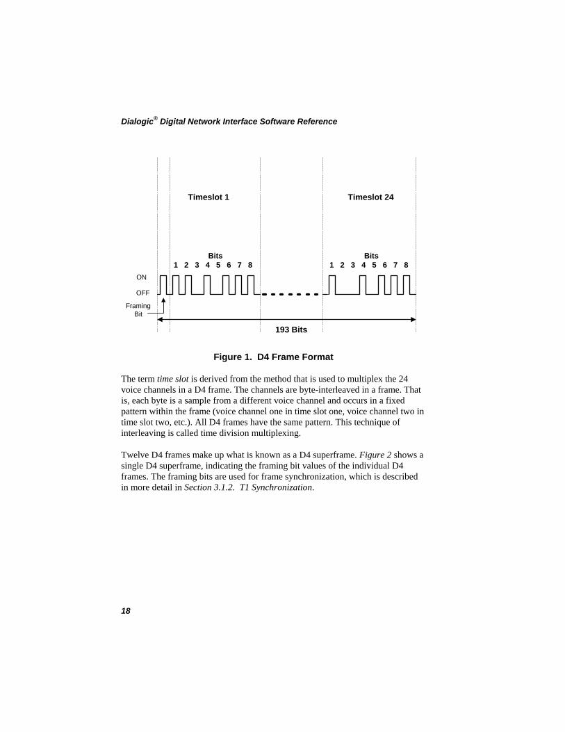
Digital data on a T1 line is organized into D4 frames. A D4 frame consists of a single 8-bit sample from each of the 24 voice channels and one framing bit, for a total of 193 bits. Each 8-bit sample occupies what is known as a time slot within the frame. Figure 1 shows one D4 frame.
17
Dialogic® Digital Network Interface Software Reference
ON
OFF
FramingBit
Timeslot 1
Bits1 2 3 4 5 6 7 8
Timeslot 24
Bits1 2 3 4 5 6 7 8
193 Bits
Figure 1. D4 Frame Format
The term time slot is derived from the method that is used to multiplex the 24 voice channels in a D4 frame. The channels are byte-interleaved in a frame. That is, each byte is a sample from a different voice channel and occurs in a fixed pattern within the frame (voice channel one in time slot one, voice channel two in time slot two, etc.). All D4 frames have the same pattern. This technique of interleaving is called time division multiplexing.
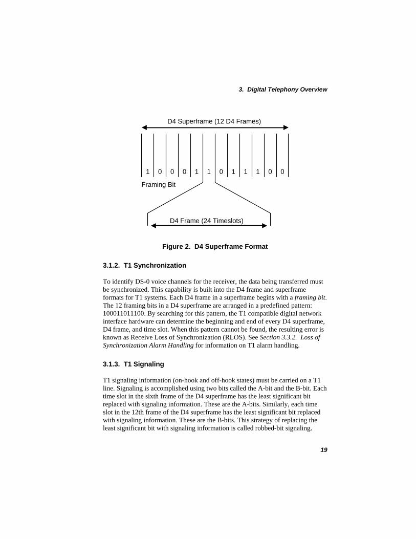
Twelve D4 frames make up what is known as a D4 superframe. Figure 2 shows a single D4 superframe, indicating the framing bit values of the individual D4 frames. The framing bits are used for frame synchronization, which is described in more detail in Section 3.1.2. T1 Synchronization.
18
3. Digital Telephony Overview
1 1 1 1 1
Framing Bit
1 0 00000
D4 Frame (24 Timeslots)
D4 Superframe (12 D4 Frames)
Figure 2. D4 Superframe Format
3.1.2. T1 Synchronization
To identify DS-0 voice channels for the receiver, the data being transferred must be synchronized. This capability is built into the D4 frame and superframe formats for T1 systems. Each D4 frame in a superframe begins with a framing bit. The 12 framing bits in a D4 superframe are arranged in a predefined pattern: 100011011100. By searching for this pattern, the T1 compatible digital network interface hardware can determine the beginning and end of every D4 superframe, D4 frame, and time slot. When this pattern cannot be found, the resulting error is known as Receive Loss of Synchronization (RLOS). See Section 3.3.2. Loss of Synchronization Alarm Handling for information on T1 alarm handling.
3.1.3. T1 Signaling
T1 signaling information (on-hook and off-hook states) must be carried on a T1 line. Signaling is accomplished using two bits called the A-bit and the B-bit. Each time slot in the sixth frame of the D4 superframe has the least significant bit replaced with signaling information. These are the A-bits. Similarly, each time slot in the 12th frame of the D4 superframe has the least significant bit replaced with signaling information. These are the B-bits. This strategy of replacing the least significant bit with signaling information is called robbed-bit signaling.
19
Dialogic® Digital Network Interface Software Reference
For example, in E&M (Ear and Mouth) protocol the signaling bits indicate whether the sending party’s line is on-hook or off-hook. When the signaling bits are 0s, the line is on-hook, and when the signaling bits are 1s, the line is off-hook.
NOTE: Some T1 services reverse these values or use them in different patterns or protocols. Check with your T1 supplier to verify the A-bit and B-bit values for your T1 service.
3.2. E1 Digital Telephony
An E1 circuit is a digital two-way connection operating at a speed of 2.048 Mbps. This rate is achieved by combining 32 time slots operating at a rate of 64 Kbps.
64,000 bps (Individual Voice Channel Rate) x 32 (Number of Channels or Time Slots)
2,048,000 (E1 Circuit Rate)
These 32 time slots include 30 time slots available for up to 30 voice channels, one time slot dedicated to carrying frame synchronization information (time slot 0), and one time slot dedicated to carrying signaling information (time slot 16). The E1 compatible digital network interface boards de-multiplex the 30 voice channels and pass them on to E1 compatible resource modules.
NOTE: E1 is used to refer to the 2.048 Mbps Digital Service with Channel Associated Signaling (CAS). This service is available in Europe and some parts of Asia.
3.2.1. E1 Frame Format
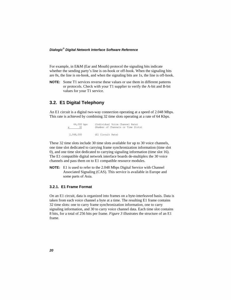
On an E1 circuit, data is organized into frames on a byte-interleaved basis. Data is taken from each voice channel a byte at a time. The resulting E1 frame contains 32 time slots: one to carry frame synchronization information, one to carry signaling information, and 30 to carry voice channel data. Each time slot contains 8 bits, for a total of 256 bits per frame. Figure 3 illustrates the structure of an E1 frame.
20
3. Digital Telephony Overview
Timeslot 1
Bits1 2 3 4 5 6 7 8
Timeslot 31
Bits1 2 3 4 5 6 7 8
256 Bits
Figure 3. E1 Frame Format
E1 frame format numbers time slots from 0 to 31.
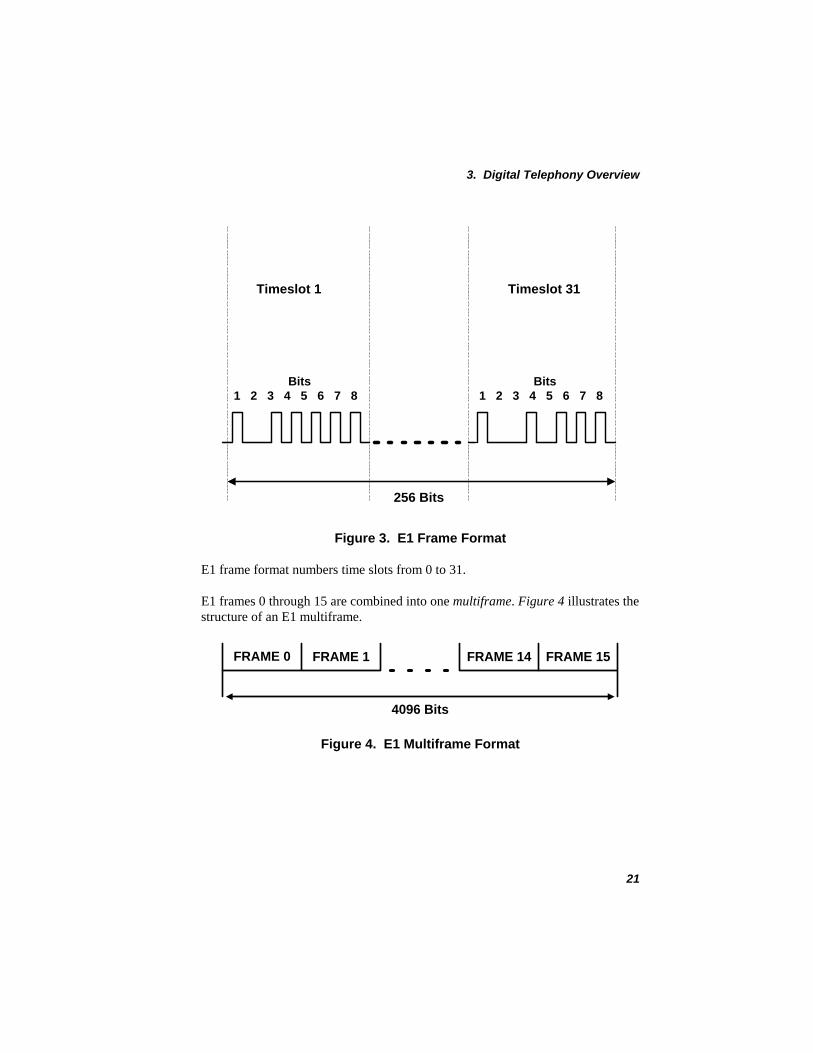
E1 frames 0 through 15 are combined into one multiframe. Figure 4 illustrates the structure of an E1 multiframe.
FRAME 0 FRAME 1 FRAME 14 FRAME 15
4096 Bits
Figure 4. E1 Multiframe Format
21
Dialogic® Digital Network Interface Software Reference
3.2.2. E1 Synchronization
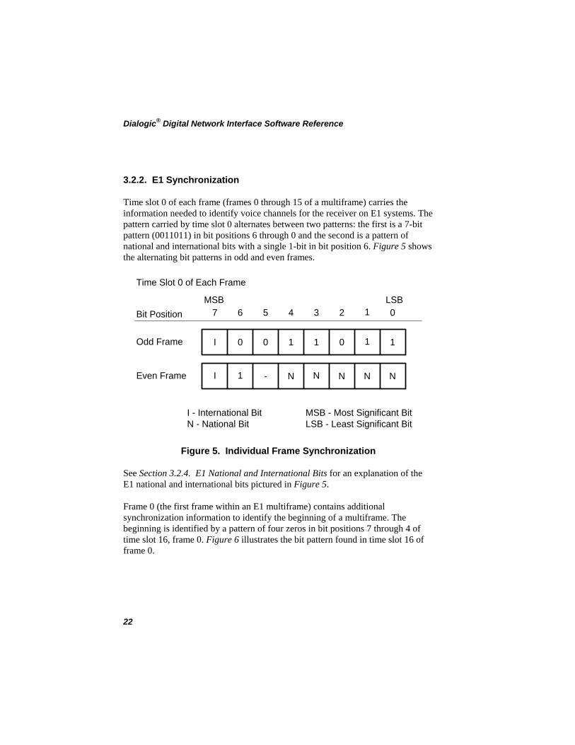
Time slot 0 of each frame (frames 0 through 15 of a multiframe) carries the information needed to identify voice channels for the receiver on E1 systems. The pattern carried by time slot 0 alternates between two patterns: the first is a 7-bit pattern (0011011) in bit positions 6 through 0 and the second is a pattern of national and international bits with a single 1-bit in bit position 6. Figure 5 shows the alternating bit patterns in odd and even frames.
Time Slot 0 of Each Frame
Bit Position
I
I
0 0 1 1 0 1 1
1 - N N N N N
7 6 5 4 3 2 1 0MSB LSB
Odd Frame
Even Frame
I - International BitN - National Bit
MSB - Most Significant BitLSB - Least Significant Bit
Figure 5. Individual Frame Synchronization
See Section 3.2.4. E1 National and International Bits for an explanation of the E1 national and international bits pictured in Figure 5.
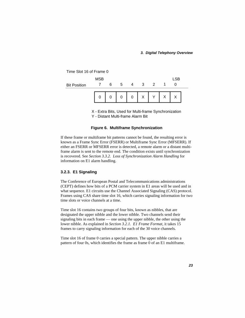
Frame 0 (the first frame within an E1 multiframe) contains additional synchronization information to identify the beginning of a multiframe. The beginning is identified by a pattern of four zeros in bit positions 7 through 4 of time slot 16, frame 0. Figure 6 illustrates the bit pattern found in time slot 16 of frame 0.
22
3. Digital Telephony Overview
Time Slot 16 of Frame 0
Bit Position
0 0 0 0 X Y X X
7 6 5 4 3 2 1 0MSB LSB
X - Extra Bits, Used for Multi-frame SynchronizationY - Distant Multi-frame Alarm Bit
Figure 6. Multiframe Synchronization
If these frame or multiframe bit patterns cannot be found, the resulting error is known as a Frame Sync Error (FSERR) or Multiframe Sync Error (MFSERR). If either an FSERR or MFSERR error is detected, a remote alarm or a distant multi-frame alarm is sent to the remote end. The condition exists until synchronization is recovered. See Section 3.3.2. Loss of Synchronization Alarm Handling for information on E1 alarm handling.
3.2.3. E1 Signaling
The Conference of European Postal and Telecommunications administrations (CEPT) defines how bits of a PCM carrier system in E1 areas will be used and in what sequence. E1 circuits use the Channel Associated Signaling (CAS) protocol. Frames using CAS share time slot 16, which carries signaling information for two time slots or voice channels at a time.
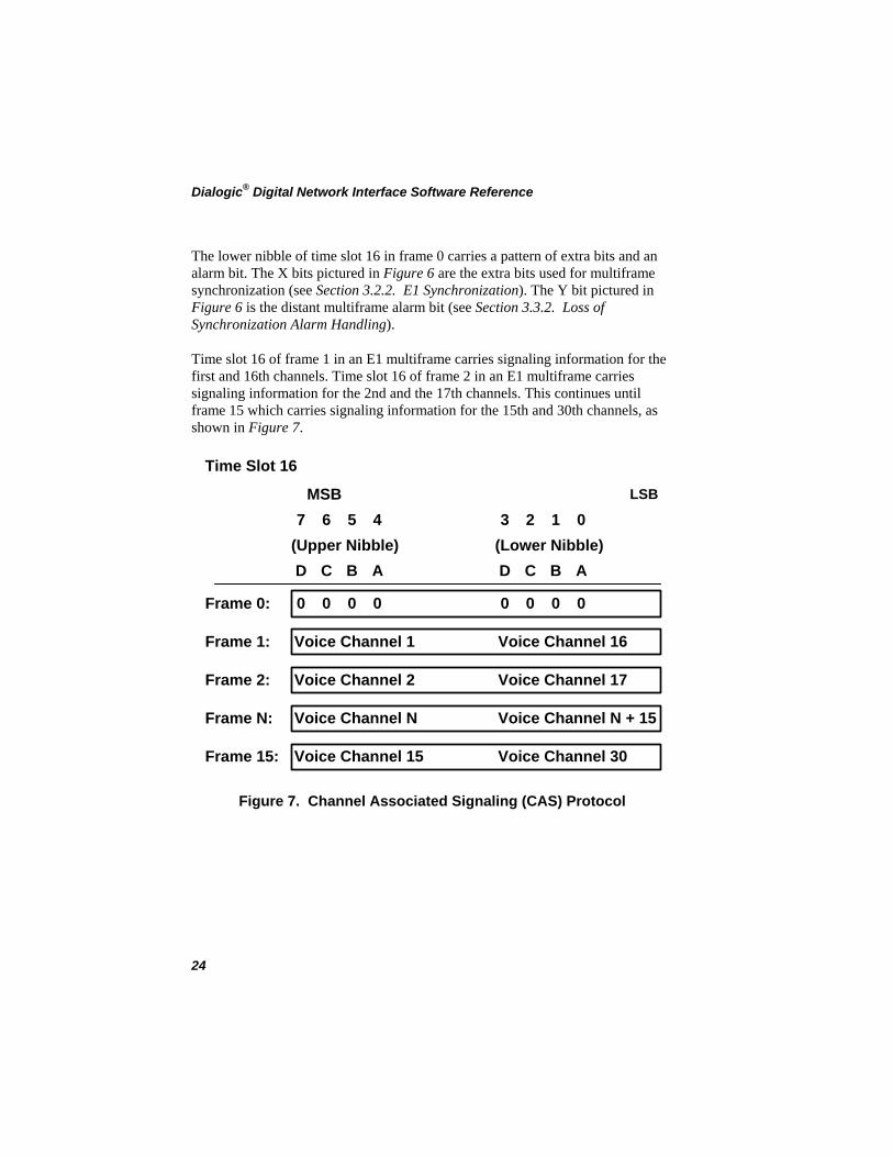
Time slot 16 contains two groups of four bits, known as nibbles, that are designated the upper nibble and the lower nibble. Two channels send their signaling bits in each frame — one using the upper nibble, the other using the lower nibble. As explained in Section 3.2.1. E1 Frame Format, it takes 15 frames to carry signaling information for each of the 30 voice channels.
Time slot 16 of frame 0 carries a special pattern. The upper nibble carries a pattern of four 0s, which identifies the frame as frame 0 of an E1 multiframe.
23
Dialogic® Digital Network Interface Software Reference
The lower nibble of time slot 16 in frame 0 carries a pattern of extra bits and an alarm bit. The X bits pictured in Figure 6 are the extra bits used for multiframe synchronization (see Section 3.2.2. E1 Synchronization). The Y bit pictured in Figure 6 is the distant multiframe alarm bit (see Section 3.3.2. Loss of Synchronization Alarm Handling).
Time slot 16 of frame 1 in an E1 multiframe carries signaling information for the first and 16th channels. Time slot 16 of frame 2 in an E1 multiframe carries signaling information for the 2nd and the 17th channels. This continues until frame 15 which carries signaling information for the 15th and 30th channels, as shown in Figure 7.
MSB LSB
Time Slot 16
Voice Channel 1 Voice Channel 16
Voice Channel 2 Voice Channel 17
Voice Channel N Voice Channel N + 15
Voice Channel 15 Voice Channel 30
0 0 0 0 0 0 0 0
D C B A
3 2 1 07 6 5 4
D C B A(Upper Nibble) (Lower Nibble)
Frame 0:
Frame 1:
Frame 2:
Frame N:
Frame 15:
Figure 7. Channel Associated Signaling (CAS) Protocol
24
3. Digital Telephony Overview
Caution
Do not set signaling bits ABCD to 0000. As explained in Section 3.2.2. E1 Synchronization, this setting is used to identify frame 0 of an
E1 multiframe.
Clear Channel TS16 Feature
The Clear Channel TS16 feature allows the use of time slot 16 for data on E1 interface boards. This feature is enabled or disabled by adding one of the following lines to /usr/dialogic/cfg/dialogic.cfg:
FEATURES = TS16_CLEAR
This command selects Clear Channel Time Slot 16 (CCTS16) for E1 interface boards, ignores E1 signaling received from the network on time slot 16, and transmits FFH. Access to time slot 16 is not available.
FEATURES = TS16_SIG
This command specifies that the E1 interface board will use the default of E1 signaling on time slot 16.
3.2.4. E1 National and International Bits
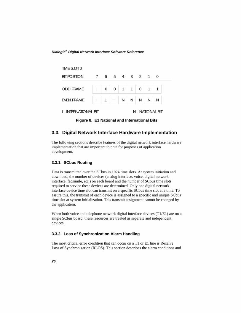
National and international bits are set in time slot 0. The most significant bit (bit position 7) in time slot 0 of each frame contains the international bit. The national bits occupy bit positions 0 through 4 of time slot 0 of every second frame. Figure 8 shows national and international bit settings.
25
Dialogic® Digital Network Interface Software Reference
TIMESLOT0
BITPOSITION
ODD FRAME
EVEN FRAME
LI - INTERNATIONA BIT N - NATIONALBIT
7 6 5 4 3 2 1 0
I 0 0 1 1 0 1 1
I 1 N N N N N
Figure 8. E1 National and International Bits
3.3. Digital Network Interface Hardware Implementation
The following sections describe features of the digital network interface hardware implementation that are important to note for purposes of application development.
3.3.1. SCbus Routing
Data is transmitted over the SCbus in 1024 time slots. At system initiation and download, the number of devices (analog interface, voice, digital network interface, facsimile, etc.) on each board and the number of SCbus time slots required to service these devices are determined. Only one digital network interface device time slot can transmit on a specific SCbus time slot at a time. To assure this, the transmit of each device is assigned to a specific and unique SCbus time slot at system initialization. This transmit assignment cannot be changed by the application.
When both voice and telephone network digital interface devices (T1/E1) are on a single SCbus board, these resources are treated as separate and independent devices.
3.3.2. Loss of Synchronization Alarm Handling
The most critical error condition that can occur on a T1 or E1 line is Receive Loss of Synchronization (RLOS). This section describes the alarm conditions and
26
3. Digital Telephony Overview
signals associated with digital network interface alarm handling and how they are indicated on a digital network interface board.
T1 Alarm Handling
For T1 applications, the T1 compatible digital network interface boards generate three alarm conditions to indicate RLOS:
• Red alarm • Yellow alarm • Blue alarm
A red alarm condition occurs when RLOS has existed for 2.5 seconds (default) on incoming data. This condition will exist until the synchronization has been recovered and remains recovered for 12 seconds (default).
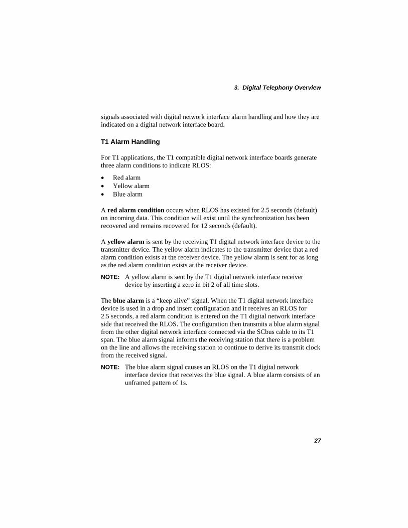
A yellow alarm is sent by the receiving T1 digital network interface device to the transmitter device. The yellow alarm indicates to the transmitter device that a red alarm condition exists at the receiver device. The yellow alarm is sent for as long as the red alarm condition exists at the receiver device.
NOTE: A yellow alarm is sent by the T1 digital network interface receiver device by inserting a zero in bit 2 of all time slots.
The blue alarm is a “keep alive” signal. When the T1 digital network interface device is used in a drop and insert configuration and it receives an RLOS for 2.5 seconds, a red alarm condition is entered on the T1 digital network interface side that received the RLOS. The configuration then transmits a blue alarm signal from the other digital network interface connected via the SCbus cable to its T1 span. The blue alarm signal informs the receiving station that there is a problem on the line and allows the receiving station to continue to derive its transmit clock from the received signal.
NOTE: The blue alarm signal causes an RLOS on the T1 digital network interface device that receives the blue signal. A blue alarm consists of an unframed pattern of 1s.
27
Dialogic® Digital Network Interface Software Reference
DTI/241 DTI/241Transmitting
NetworkDownstream
Network
Yellow alarm transmittedto network
Blue alarm transmittedto downstream device
Figure 9. T1 Alarm Conditions
E1 Alarm Handling
For E1 applications, the E1 compatible digital network interface boards generate four alarm conditions to indicate loss of synchronization (FSERR or MFSERR):
• Remote alarm • Unframed all 1s alarm • Distant multiframe alarm • Signaling all 1s alarm
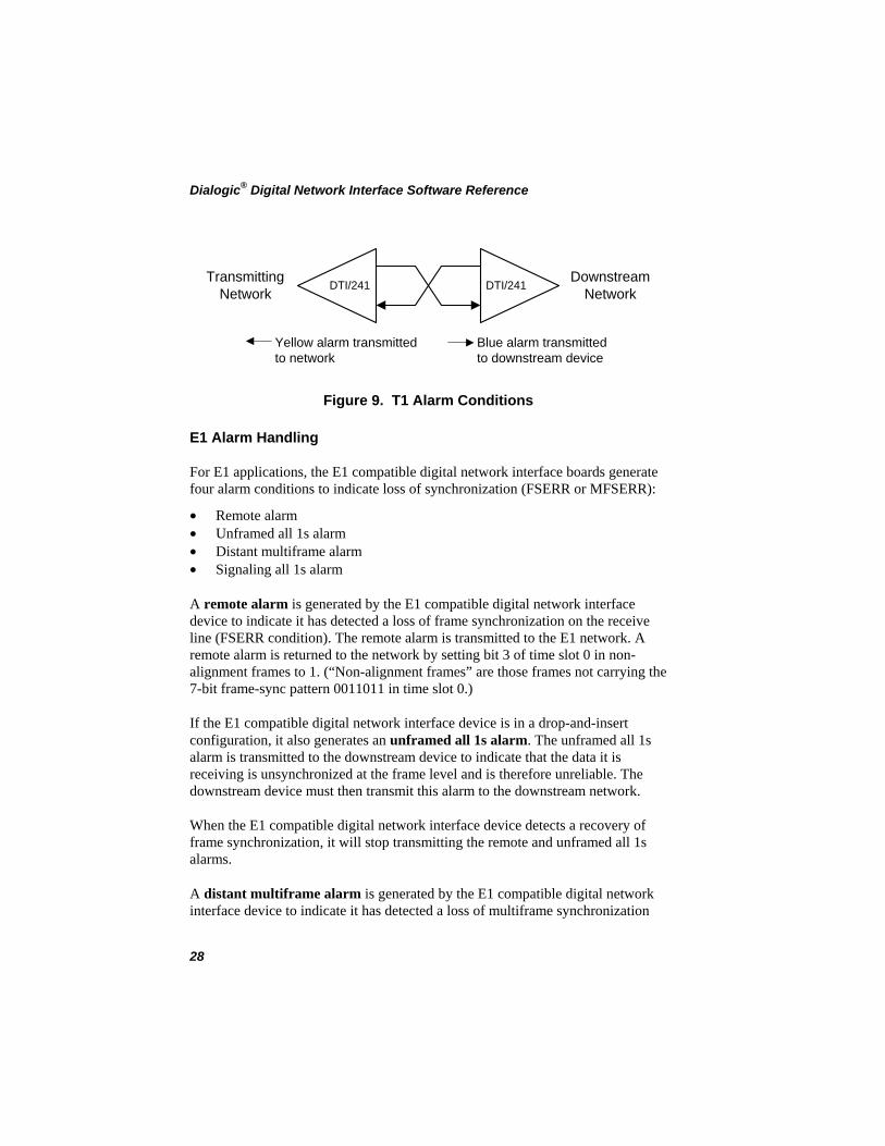
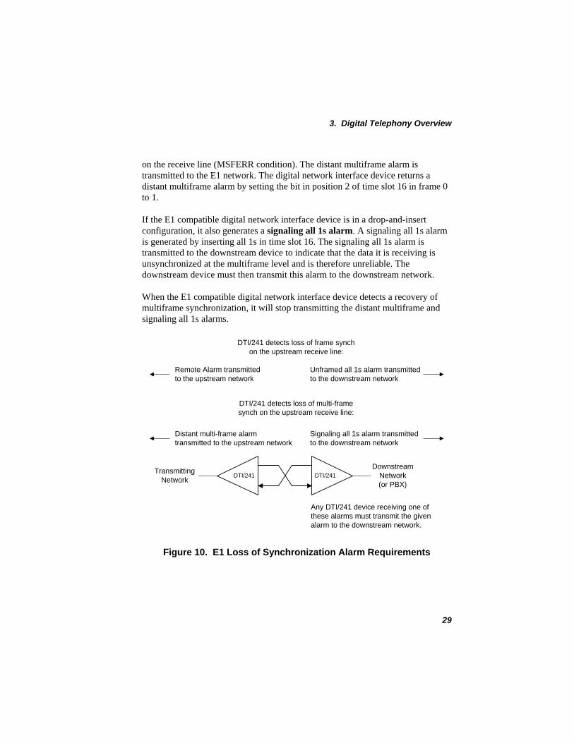
A remote alarm is generated by the E1 compatible digital network interface device to indicate it has detected a loss of frame synchronization on the receive line (FSERR condition). The remote alarm is transmitted to the E1 network. A remote alarm is returned to the network by setting bit 3 of time slot 0 in non-alignment frames to 1. (“Non-alignment frames” are those frames not carrying the 7-bit frame-sync pattern 0011011 in time slot 0.)
If the E1 compatible digital network interface device is in a drop-and-insert configuration, it also generates an unframed all 1s alarm. The unframed all 1s alarm is transmitted to the downstream device to indicate that the data it is receiving is unsynchronized at the frame level and is therefore unreliable. The downstream device must then transmit this alarm to the downstream network.
When the E1 compatible digital network interface device detects a recovery of frame synchronization, it will stop transmitting the remote and unframed all 1s alarms.
A distant multiframe alarm is generated by the E1 compatible digital network interface device to indicate it has detected a loss of multiframe synchronization
28
3. Digital Telephony Overview
on the receive line (MSFERR condition). The distant multiframe alarm is transmitted to the E1 network. The digital network interface device returns a distant multiframe alarm by setting the bit in position 2 of time slot 16 in frame 0 to 1.
If the E1 compatible digital network interface device is in a drop-and-insert configuration, it also generates a signaling all 1s alarm. A signaling all 1s alarm is generated by inserting all 1s in time slot 16. The signaling all 1s alarm is transmitted to the downstream device to indicate that the data it is receiving is unsynchronized at the multiframe level and is therefore unreliable. The downstream device must then transmit this alarm to the downstream network.
When the E1 compatible digital network interface device detects a recovery of multiframe synchronization, it will stop transmitting the distant multiframe and signaling all 1s alarms.
DTI/241 DTI/241Transmitting
Network
DownstreamNetwork(or PBX)
DTI/241 detects loss of frame synchon the upstream receive line:
Remote Alarm transmittedto the upstream network
DTI/241 detects loss of multi-framesynch on the upstream receive line:
Distant multi-frame alarmtransmitted to the upstream network
Unframed all 1s alarm transmittedto the downstream network
Signaling all 1s alarm transmittedto the downstream network
Any DTI/241 device receiving one ofthese alarms must transmit the givenalarm to the downstream network.
Figure 10. E1 Loss of Synchronization Alarm Requirements
29
Dialogic® Digital Network Interface Software Reference
3.3.3. Digital Network Interface Hardware Alarm Indicators
The three LEDs on the rear bracket of the digital network interface board indicate the state of the signal being received. All LED indicators will remain lit until the digital network interface firmware is downloaded to the device.
Red LED: The red LED lights up whenever the digital network interface device detects RLOS.
Yellow LED: A yellow LED lights up whenever the digital network interface device receives an alarm indicating that a network span is receiving unsynchronized data from the digital network interface board.
Green LED: A green LED is lit whenever the digital network interface board is receiving a signal.
NOTES: 1. Red, yellow, and green LEDs will be lit when the system is powered up, regardless of whether a signal is being received.
2. No alarm handling is performed until digital network interface boards are downloaded.
3. Once the firmware is downloaded, the default alarm handling mode for digital network interface boards is terminate alarm handling [see dt_setalrm( )].
30
4. Function Overview This chapter describes the Dialogic® Digital Network Interface API library functions that control the digital network interface hardware. A complete reference describing these functions in detail is located in Chapter 5. Function Reference.
4.1. Dialogic® Digital Network Interface API Library Function Categories
The Dialogic® Digital Network Interface API library functions provide the building blocks to create voice applications using T1 or E1 lines. These functions can be divided into the following categories:
• Alarm functions - control T1 or E1 alarm handling • Diagnostic functions - test digital network interface hardware • Extended Attribute functions - retrieve device-specific attribute data • Parameter Request functions - request device parameters • Parameter Setting functions - set device parameters • Resource Management functions - open and close digital network interface
devices • Routing functions - generate communication between devices connected to
time slots • Statistics functions – return the statistics queried • Time Slot Audio functions - generate audio signals on time slots • Time Slot Signaling functions - alter signaling portion of time slot
For Dialogic® Digital Network Interface API library support on Dialogic® DM3 Boards, see Chapter 7. Dialogic® Digital Network Interface API for Dialogic® DM3 Boards.
NOTE: Many Digital Network Interface library functions can operate in either synchronous mode or asynchronous mode. Synchronous functions do not return control to the calling process until the function call is completed. To operate a function in asynchronous mode, your application must include an event handler to trap and process the completion event.
31
Dialogic® Digital Network Interface Software Reference
Each category and its functions are briefly described in the following sections.
4.1.1. Alarm Functions
• dt_setalrm( ) - set alarm handling mode • dt_xmitalrm( ) - start/stop alarm transmission
The Alarm functions allow your application to control the way T1 or E1 alarms are handled. The dt_setalrm( ) function sets the alarm-handling mode. The dt_xmitalrm( ) function starts and stops the transmission of alarms.
For a detailed discussion of T1 and E1 alarm handling, refer to Chapter 3. Digital Telephony Overview.
4.1.2. Diagnostic Functions
• dt_rundiag( ) - run diagnostics on network firmware • dt_tstcom( ) - test board interface communications • dt_tstdat( ) - run data test on board device
The Diagnostic functions check the network firmware and hardware. The dt_rundiag( ) function runs diagnostics on the network firmware and the other two functions test the hardware. The dt_tstcom( ) function tests communication between the PC and the digital network interface device. The dt_tstdat( ) function tests the reliability of data transfer between the PC and the digital network interface device.
4.1.3. Extended Attribute Functions
• ATDT_BDMODE( ) - board signaling mode (all time slots) • ATDT_BDSGBIT( ) - board signaling bits (all time slots) • ATDT_DNLDVER( ) - downloaded network firmware version • ATDT_IDLEST( ) - time slot idling state • ATDT_ROMVER( ) - EPROM version • ATDT_STATUS( ) - time slot status • ATDT_TSMODE( ) - get time slot signaling mode • ATDT_TSSGBIT( ) - get time slot signaling bits
32
4. Function Overview
Standard Attribute functions, which are contained in the Dialogic® Standard Runtime Library (SRL, see Appendix A – Dialogic® Standard Runtime Library), provide generic information about a device, such as its name or the status of the last function call of the device. Extended Attribute functions return device specific information. The Digital Network Interface library Extended Attribute functions return information about digital network interface logical board and time slot devices.
Extended Attribute function error handling is similar to that of other Digital Network Interface library functions. Most Extended Attribute functions return AT_FAILURE on error. One Extended Attribute function, ATDT_BDSGBIT( ), returns the value AT_FAILUREP on error. Refer to Section 4.2. Error Handlingfor information about retrieving errors.
4.1.4. Parameter Request Functions
• dt_getparm( ) - get device parameter • dt_getevt( ) - blocks and returns control after event • dt_getevtmsk( ) - get device event bitmask
Parameter Request functions are used to check the status of network parameter and event mask settings.
4.1.5. Parameter Setting Functions
• dt_setparm( ) - change device parameter • dt_setevtmsk( ) - change device event mask
The Parameter Setting functions set network device parameters and masks used for event management.
4.1.6. Resource Management Functions
• dt_open( ) - open board or time slot device • dt_close( ) - close board or time slot device
Resource Management functions open and close devices. Before you can perform an operation on a device, the device must be opened. The dt_open( ) function
33
Dialogic® Digital Network Interface Software Reference
returns a unique device handle. All subsequent operations on the device must use this handle.
NOTES: 1. A device handle is NOT the same as a system file handle.
2. Opening or closing a digital network interface device does not affect other processes using the device. (See Chapter 6. Application Guidelines, for more information on opening and using DTI devices.)
3. The value returned by dt_open( ) for a digital network interface logical board is referred to as a logical board device handle in this guide.
4.1.7. Routing Functions
• dt_getctinfo( ) - get information about the digital network interface time slot device connected to the SCbus
• dt_getxmitslot( ) - returns SCbus time slot connected to the digital network interface time slot device
• dt_listen( ) - connects the receive of a digital network interface time slot device to an SCbus time slot
• dt_unlisten( ) - disconnects the receive of a digital network interface time slot device from an SCbus time slot
Routing functions enable the application to make or break a connection between voice, telephone network interface, and other resource channels connected via SCbus time slots.
4.1.8. Statistics Functions
• dt_getstatistics( ) – return the statistics queried
The dt_getstatistics( ) function returns the statistics queried. The application must specify the type of statistics to be queried in the TsdtStatisticsList structure.
4.1.9. Time Slot Audio Functions
• dt_setidle( ) - enable/disable time slot idle state
34
4. Function Overview
A Time Slot Audio function affects only the transmitted audio portion of a time slot. It replaces the normal voice data on the audio portion of a time slot with other data. The dt_setidle( ) function transmits an idle pattern (digital equivalent of silence) on the selected digital network interface time slot. The specific idle pattern transmitted can be specified via the download configuration file or by using the dt_setparm( ) function.
4.1.10. Time Slot Signaling Functions
• dt_dial( ) - dial a pulse digit string • dt_setsigmod( ) - change time slot transmit signaling mode • dt_settssig( ) - change time slot signaling bits • dt_settssigsim( ) - clear and set signaling bits simultaneously • dt_xmitwink( ) - transmit wink signaling
Time Slot Signaling functions affect the transmitted signaling portion of a time slot. The dt_setsigmod( ) function selects the origin of the signaling information. The signaling information can either be inserted by the digital network interface hardware or derived (by way of the SCbus) from an SCbus compatible resource device (such as a Dialogic® D/240SC-T1 Board) or another network device. The dt_settssig( ) function sets the state of the signaling bits when the signaling information is inserted by the Dialogic® Digital Network Interface Board (signaling insertion mode). The dt_xmitwink( ) function transmits wink signaling to the network on any of the available signaling bits (for T1, bit A or B; for E1, bit A, B, C, or D).
NOTES: 1. The signaling bit and polarity used for wink signaling are only configurable through the download parameter file.
2. If your configuration includes Dialogic® Voice Boards, you can use the Dialogic® Voice Library function dx_dial( ) instead.
35
Dialogic® Digital Network Interface Software Reference
4.2. Error Handling
All Dialogic® Digital Network Interface Library functions return a value that indicates the success or failure of the function call. Generally, Digital Network Interface Library functions return the following values:
• 0 - function success • -1 - general error • AT_FAILURE - Extended Attribute function error from a function that
returns a value • AT_FAILUREP - Extended Attribute function error from a function that
returns a pointer
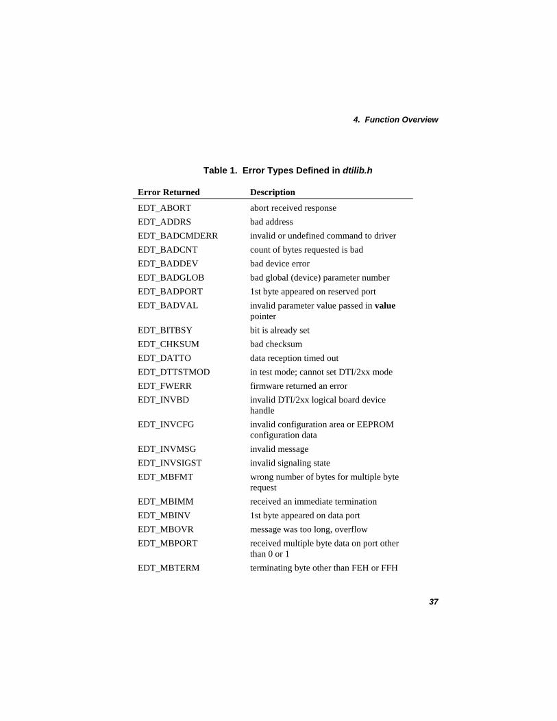
If a function fails, the error code can be retrieved using the Dialogic® Standard Runtime Library (SRL) ATDV_LASTERR( ) function. The error codes are defined in dtilib.h and listed in Table 1.
NOTES: 1. The network dt_open( ) function call returns a device handle if the function call is successful. A device handle is a positive non-zero value. If dt_open( ) fails, the return code is -1 and the specific error is a system error that can be found in the global variable errno, contained in errno.h.
2. The ATDT_BDSGBIT( ) function call returns the value AT_FAILUREP on error. All other Extended Attribute functions return AT_FAILURE on error.
3. The SRL Standard Attribute functions ATDV_LASTERR( ) and ATDV_ERRMSGP( ) can be used to obtain the status of the last function call of the device. Refer to Appendix A – Dialogic® Standard Runtime Library for more information.
4. If the error returned by ATDV_LASTERR( ) is EDT_SYSTEM, a system error has occurred. Check the value of the global variable errno defined in errno.h.
36
4. Function Overview
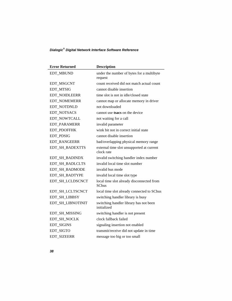
Table 1. Error Types Defined in dtilib.h
Error Returned Description
EDT_ABORT abort received response EDT_ADDRS bad address EDT_BADCMDERR invalid or undefined command to driver EDT_BADCNT count of bytes requested is bad EDT_BADDEV bad device error EDT_BADGLOB bad global (device) parameter number EDT_BADPORT 1st byte appeared on reserved port EDT_BADVAL invalid parameter value passed in value
pointer EDT_BITBSY bit is already set EDT_CHKSUM bad checksum EDT_DATTO data reception timed out EDT_DTTSTMOD in test mode; cannot set DTI/2xx mode EDT_FWERR firmware returned an error EDT_INVBD invalid DTI/2xx logical board device
handle EDT_INVCFG invalid configuration area or EEPROM
configuration data EDT_INVMSG invalid message EDT_INVSIGST invalid signaling state EDT_MBFMT wrong number of bytes for multiple byte
request EDT_MBIMM received an immediate termination EDT_MBINV 1st byte appeared on data port EDT_MBOVR message was too long, overflow EDT_MBPORT received multiple byte data on port other
than 0 or 1 EDT_MBTERM terminating byte other than FEH or FFH
37
Dialogic® Digital Network Interface Software Reference
Error Returned Description
EDT_MBUND under the number of bytes for a multibyte request
EDT_MSGCNT count received did not match actual count EDT_MTSIG cannot disable insertion EDT_NOIDLEERR time slot is not in idle/closed state EDT_NOMEMERR cannot map or allocate memory in driver EDT_NOTDNLD not downloaded EDT_NOTSACS cannot use tsacs on the device EDT_NOWTCALL not waiting for a call EDT_PARAMERR invalid parameter EDT_PDOFFHK wink bit not in correct initial state EDT_PDSIG cannot disable insertion EDT_RANGEERR bad/overlapping physical memory range EDT_SH_BADEXTTS external time slot unsupported at current
clock rate EDT_SH_BADINDX invalid switching handler index number EDT_SH_BADLCLTS invalid local time slot number EDT_SH_BADMODE invalid bus mode EDT_SH_BADTYPE invalid local time slot type EDT_SH_LCLDSCNCT local time slot already disconnected from
SCbus EDT_SH_LCLTSCNCT local time slot already connected to SCbus EDT_SH_LIBBSY switching handler library is busy EDT_SH_LIBNOTINIT switching handler library has not been
initialized EDT_SH_MISSING switching handler is not present EDT_SH_NOCLK clock fallback failed EDT_SIGINS signaling insertion not enabled EDT_SIGTO transmit/receive did not update in time EDT_SIZEERR message too big or too small
38
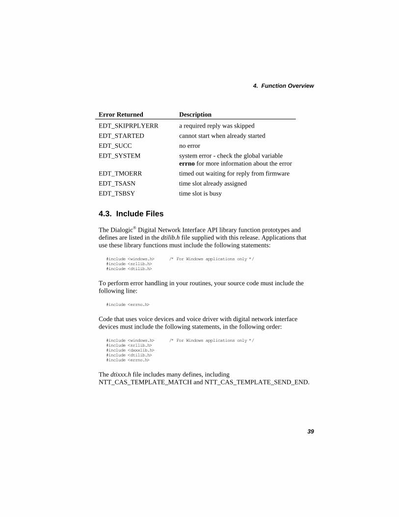
4. Function Overview
Error Returned Description
EDT_SKIPRPLYERR a required reply was skipped EDT_STARTED cannot start when already started EDT_SUCC no error EDT_SYSTEM system error - check the global variable
errno for more information about the error EDT_TMOERR timed out waiting for reply from firmware EDT_TSASN time slot already assigned EDT_TSBSY time slot is busy
4.3. Include Files
The Dialogic® Digital Network Interface API library function prototypes and defines are listed in the dtilib.h file supplied with this release. Applications that use these library functions must include the following statements:
#include <windows.h> /* For Windows applications only */ #include <srllib.h> #include <dtilib.h>
To perform error handling in your routines, your source code must include the following line:
#include <errno.h>
Code that uses voice devices and voice driver with digital network interface devices must include the following statements, in the following order:
#include <windows.h> /* For Windows applications only */ #include <srllib.h> #include <dxxxlib.h> #include <dtilib.h> #include <errno.h>
The dtixxx.h file includes many defines, including NTT_CAS_TEMPLATE_MATCH and NTT_CAS_TEMPLATE_SEND_END.
39

Dialogic® Digital Network Interface Software Reference
40
5. Function Reference
This chapter contains an alphabetical listing of all Dialogic® Digital Network Interface API Library functions. Extended Attribute functions, also contained in the Digital Network Interface Library, are described here as well. (Because the functions appear alphabetically, the Extended Attribute functions are located together near the front of the reference.) For information about Standard Attribute functions, refer to Appendix A – Dialogic® Standard Runtime Library.
For Digital Network Interface Library support on Dialogic® DM3 Boards, see Chapter 7. Dialogic® Digital Network Interface API for Dialogic® DM3 Boards.
NOTE: Unless otherwise noted, all functions listed in this section apply to both Linux and Windows® operating systems.
41
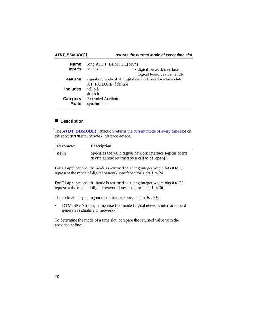
ATDT_BDMODE( ) returns the current mode of every time slot
long ATDT_BDMODE(devh) Name: Inputs: int devh • digital network interface
logical board device handle signaling mode of all digital network interface time slots AT_FAILURE if failure
Returns:
srllib.h dtilib.h
Includes:
Extended Attribute Category: synchronous Mode:
Description
The ATDT_BDMODE( ) function returns the current mode of every time slot on the specified digital network interface device.
Parameter Description
devh Specifies the valid digital network interface logical board device handle returned by a call to dt_open( )
For T1 applications, the mode is returned as a long integer where bits 0 to 23 represent the mode of digital network interface time slots 1 to 24.
For E1 applications, the mode is returned as a long integer where bits 0 to 29 represent the mode of digital network interface time slots 1 to 30.
The following signaling mode defines are provided in dtilib.h:
• DTM_SIGINS - signaling insertion mode (digital network interface board generates signaling to network)
To determine the mode of a time slot, compare the returned value with the provided defines.
42
returns the current mode of every time slot ATDT_BDMODE( )
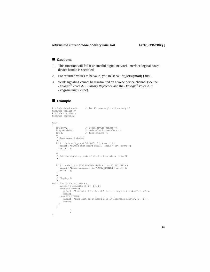
Cautions
1. This function will fail if an invalid digital network interface logical board device handle is specified.
2. For returned values to be valid, you must call dt_setsigmod( ) first.
3. Wink signaling cannot be transmitted on a voice device channel (see the Dialogic® Voice API Library Reference and the Dialogic® Voice API Programming Guide).
Example
#include <windows.h> /* For Windows applications only */ #include <srllib.h> #include <dtilib.h> #include <errno.h>
main() { int devh; /* Board device handle */ long modebits; /* Mode of all time slots */ int i; /* Loop counter */ /* * Open board 1 device */ if ( ( devh = dt_open( "dtiB1", 0 ) ) == -1 ) { printf( "Cannot open board dtiB1. errno = %d", errno ); exit( 1 ); } /* * Get the signaling mode of all E-1 time slots (1 to 30) */
if ( ( modebits = ATDT_BDMODE( devh ) ) == AT_FAILURE ) { printf( "Error message = %s.",ATDV_ERRMSGP( devh ) ); exit( 1 ); } /* * Display it */ for ( i = 0; i < 30; i++ ) { switch( ( modebits >> i ) & 1 ) { case DTM_TRANSP: printf( "Time slot %d on board 1 is in transparent mode\n", i + 1 ); break; case DTM_SIGINS: printf( "Time slot %d on board 1 is in insertion mode\n", i + 1 ); break; } } . . }
43
ATDT_BDMODE( ) returns the current mode of every time slot
Errors
If the function returns AT_FAILURE, use the SRL Standard Attribute function ATDV_LASTERR( ) to obtain the error code or use ATDV_ERRMSGP( ) to obtain a descriptive error message. See Appendix A – Dialogic® Standard Runtime Library for more information on SRL functions. The error codes returned by ATDV_LASTERR( ) are:
• EDT_BADBRDERR - digital network interface missing or defective • EDT_BADCMDERR - invalid command parameter to driver • EDT_INVBD - invalid digital network interface logical board device handle • EDT_INVMSG - invalid message • EDT_NOMEMERR - cannot map or allocate memory in driver • EDT_RANGERR - bad/overlapping physical memory range • EDT_SIZEERR - message too big or too small • EDT_SKIPRPLYERR - a required reply was skipped • EDT_SYSTEM - system error - check the global variable errno for more
information about the error • EDT_TMOERR - timed out waiting for reply from firmware
Error defines can be found in the file dtilib.h.
See Also • ATDT_BDSGBIT( ) • ATDT_TSMODE( ) • ATDT_TSSGBIT( ) • dt_setsigmod( ) • dt_settssig( )
44
returns the current state of the transmit and receive bits ATDT_BDSGBIT( )
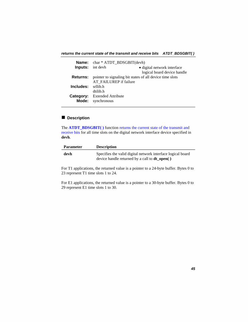
char * ATDT_BDSGBIT(devh) Name: Inputs: int devh • digital network interface
logical board device handle pointer to signaling bit states of all device time slots AT_FAILUREP if failure
Returns:
srllib.h dtilib.h
Includes:
Extended Attribute Category: synchronous Mode:
Description
The ATDT_BDSGBIT( ) function returns the current state of the transmit and receive bits for all time slots on the digital network interface device specified in devh.
Parameter Description
devh Specifies the valid digital network interface logical board device handle returned by a call to dt_open( )
For T1 applications, the returned value is a pointer to a 24-byte buffer. Bytes 0 to 23 represent T1 time slots 1 to 24.
For E1 applications, the returned value is a pointer to a 30-byte buffer. Bytes 0 to 29 represent E1 time slots 1 to 30.
45
ATDT_BDSGBIT( ) returns the current state of the transmit and receive bits
The following symbols represent each signaling bit and are defined in dtilib.h:
• DTSG_RCVA - “A” receive signaling bit • DTSG_RCVB - “B” receive signaling bit • DTSG_RCVC - “C” receive signaling bit (E1 only) • DTSG_RCVD - “D” receive signaling bit (E1 only) • DTSG_XMTA - “A” transmit signaling bit • DTSG_XMTB - “B” transmit signaling bit • DTSG_XMTC - “C” transmit signaling bit (E1 only) • DTSG_XMTD - “D” transmit signaling bit (E1 only)
To determine the state of the signaling bits, perform a logical AND operation on the byte buffer and the defines, as demonstrated in the example below.
Cautions
1. This function will fail if an invalid digital network interface logical board device handle is specified. AT_FAILUREP will be returned.
2. The transmit signaling bits are only valid when the device is in signaling insertion mode.
46
returns the current state of the transmit and receive bits ATDT_BDSGBIT( )
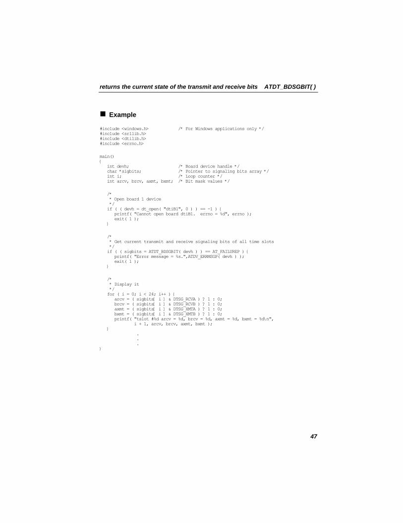
Example
#include <windows.h> /* For Windows applications only */ #include <srllib.h> #include <dtilib.h> #include <errno.h>
main() { int devh; /* Board device handle */ char *sigbits; /* Pointer to signaling bits array */ int i; /* Loop counter */ int arcv, brcv, axmt, bxmt; /* Bit mask values */
/* * Open board 1 device */ if ( ( devh = dt_open( "dtiB1", 0 ) ) == -1 ) { printf( "Cannot open board dtiB1. errno = %d", errno ); exit( 1 ); }
/* * Get current transmit and receive signaling bits of all time slots */ if ( ( sigbits = ATDT_BDSGBIT( devh ) ) == AT_FAILUREP ) { printf( "Error message = %s.",ATDV_ERRMSGP( devh ) ); exit( 1 ); }
/* * Display it */ for ( i = 0; i < 24; i++ ) { arcv = ( sigbits[ i ] & DTSG_RCVA ) ? 1 : 0; brcv = ( sigbits[ i ] & DTSG_RCVB ) ? 1 : 0; axmt = ( sigbits[ i ] & DTSG_XMTA ) ? 1 : 0; bxmt = ( sigbits[ i ] & DTSG_XMTB ) ? 1 : 0; printf( "tslot #%d arcv = %d, brcv = %d, axmt = %d, bxmt = %d\n", i + 1, arcv, brcv, axmt, bxmt ); } . . . }
47
ATDT_BDSGBIT( ) returns the current state of the transmit and receive bits
Errors
If the function returns AT_FAILUREP, use the SRL Standard Attribute function ATDV_LASTERR( ) to obtain the error code or use ATDV_ERRMSGP( ) to obtain a descriptive error message. See Appendix A – Dialogic® Standard Runtime Library for more information on SRL functions. The error codes returned by ATDV_LASTERR( ) are:
• EDT_BADBRDERR - digital network interface missing or defective • EDT_BADCMDERR - invalid or undefined command to driver • EDT_INVBD - invalid digital network interface logical board device handle • EDT_INVMSG - invalid message • EDT_NOMEMERR - cannot map or allocate memory in driver • EDT_RANGEERR - bad/overlapping physical memory range • EDT_SIZERR - message too big or too small • EDT_SKIPRPLYERR - a required reply was skipped • EDT_SYSTEM - system error - check the global variable errno for more
information about the error • EDT_TMOERR - timed out waiting for reply from firmware
Error defines can be found in the file dtilib.h.
See Also
• ATDT_BDMODE( ) • ATDT_TSMODE( ) • ATDT_TSSGBIT( ) • dt_setsigmod( ) • dt_settssig( )
48
returns the firmware version ATDT_DNLDVER( )
long ATDT_DNLDVER(devh) Name: Inputs: int devh • digital network interface
logical board device handle version of firmware used by the device AT_FAILURE if failure
Returns:
srllib.h dtilib.h
Includes:
Extended Attribute Category: synchronous Mode:
Description
The ATDT_DNLDVER( ) function returns the firmware version downloaded to the device specified in devh. This number is returned in the standard version numbering format.
Parameter Description
devh Specifies the valid digital network interface logical board device handle returned by a call to dt_open( )
Version Numbering
A version number consists of two parts that provide:
1. The release TYPE (Example: Production or Beta)
2. The release NUMBER, which consists of different elements depending on the type of release, for example:
• 1.00 Production • 1.00 Beta 5
NOTE: The examples above are shown in the convention used to display version numbers.
This function returns the version number as a long integer (32 bits) in BCD (binary coded decimal) format.
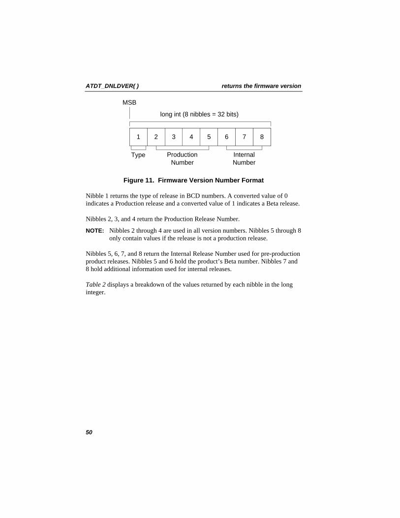
Figure 11 shows the format of the version number returned. Each section in the diagram represents a nibble (4 bits).
49
ATDT_DNLDVER( ) returns the firmware version
1 2 876543
long int (8 nibbles = 32 bits)
MSB
Type ProductionNumber
InternalNumber
Figure 11. Firmware Version Number Format
Nibble 1 returns the type of release in BCD numbers. A converted value of 0 indicates a Production release and a converted value of 1 indicates a Beta release.
Nibbles 2, 3, and 4 return the Production Release Number.
NOTE: Nibbles 2 through 4 are used in all version numbers. Nibbles 5 through 8 only contain values if the release is not a production release.
Nibbles 5, 6, 7, and 8 return the Internal Release Number used for pre-production product releases. Nibbles 5 and 6 hold the product’s Beta number. Nibbles 7 and 8 hold additional information used for internal releases.
Table 2 displays a breakdown of the values returned by each nibble in the long integer.
50
returns the firmware version ATDT_DNLDVER( )
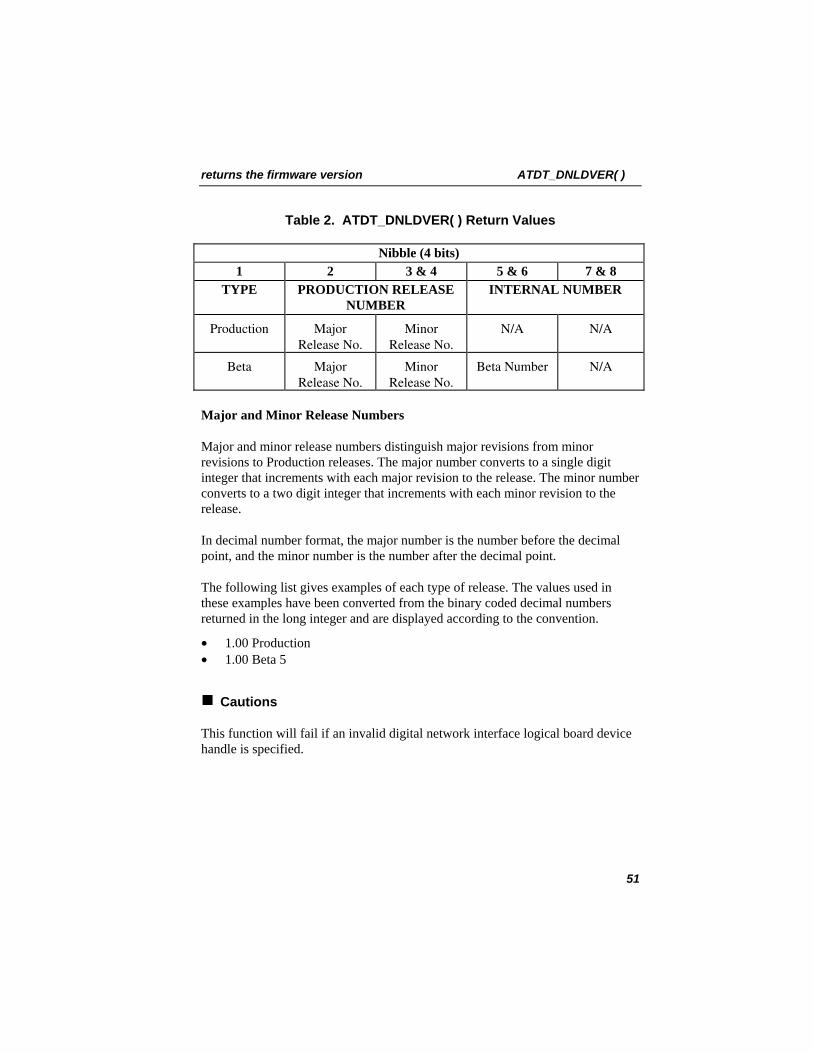
Table 2. ATDT_DNLDVER( ) Return Values
Nibble (4 bits) 1 2 3 & 4 5 & 6 7 & 8
TYPE PRODUCTION RELEASE NUMBER
INTERNAL NUMBER
Production Major Release No.
Minor Release No.
N/A N/A
Beta Major Release No.
Minor Release No.
Beta Number N/A
Major and Minor Release Numbers
Major and minor release numbers distinguish major revisions from minor revisions to Production releases. The major number converts to a single digit integer that increments with each major revision to the release. The minor number converts to a two digit integer that increments with each minor revision to the release.
In decimal number format, the major number is the number before the decimal point, and the minor number is the number after the decimal point.
The following list gives examples of each type of release. The values used in these examples have been converted from the binary coded decimal numbers returned in the long integer and are displayed according to the convention.
• 1.00 Production • 1.00 Beta 5
Cautions
This function will fail if an invalid digital network interface logical board device handle is specified.
51
ATDT_DNLDVER( ) returns the firmware version
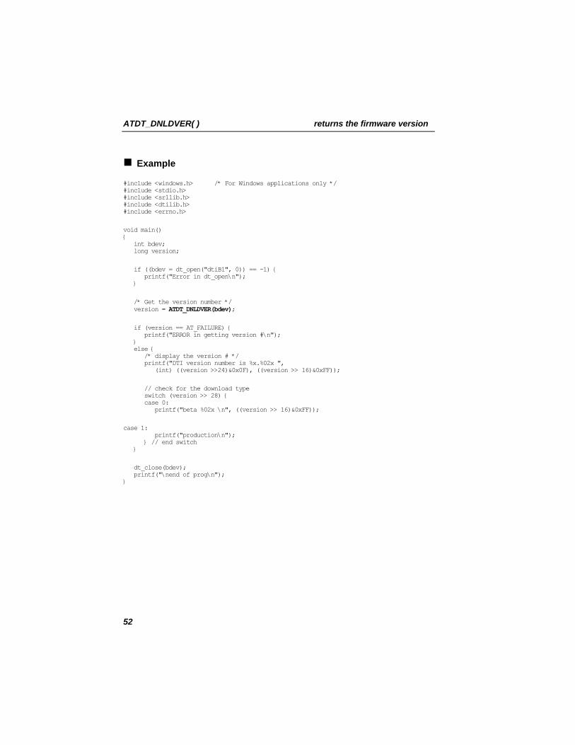
Example
#include <windows.h> /* For Windows applications only */ #include <stdio.h> #include <srllib.h> #include <dtilib.h> #include <errno.h>
void main() { int bdev; long version;
if ((bdev = dt_open("dtiB1", 0)) == -1) { printf("Error in dt_open\n"); }
/* Get the version number */ version = ATDT_DNLDVER(bdev);
if (version == AT_FAILURE) { printf("ERROR in getting version #\n"); } else { /* display the version # */ printf("DTI version number is %x.%02x ", (int) ((version >>24)&0x0F), ((version >> 16)&0xFF));
// check for the download type switch (version >> 28) { case 0: printf("beta %02x \n", ((version >> 16)&0xFF));
case 1: printf("production\n"); } // end switch }
dt_close(bdev); printf("\nend of prog\n"); }
52
returns the firmware version ATDT_DNLDVER( )
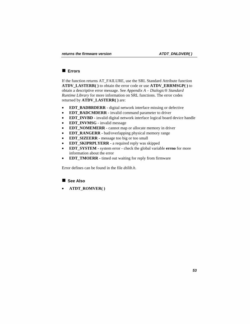
Errors
If the function returns AT_FAILURE, use the SRL Standard Attribute function ATDV_LASTERR( ) to obtain the error code or use ATDV_ERRMSGP( ) to obtain a descriptive error message. See Appendix A – Dialogic® Standard Runtime Library for more information on SRL functions. The error codes returned by ATDV_LASTERR( ) are:
• EDT_BADBRDERR - digital network interface missing or defective • EDT_BADCMDERR - invalid command parameter to driver • EDT_INVBD - invalid digital network interface logical board device handle • EDT_INVMSG - invalid message • EDT_NOMEMERR - cannot map or allocate memory in driver • EDT_RANGERR - bad/overlapping physical memory range • EDT_SIZEERR - message too big or too small • EDT_SKIPRPLYERR - a required reply was skipped • EDT_SYSTEM - system error - check the global variable errno for more
information about the error • EDT_TMOERR - timed out waiting for reply from firmware
Error defines can be found in the file dtilib.h.
See Also
• ATDT_ROMVER( )
53
ATDT_IDLEST( ) returns the current idle state
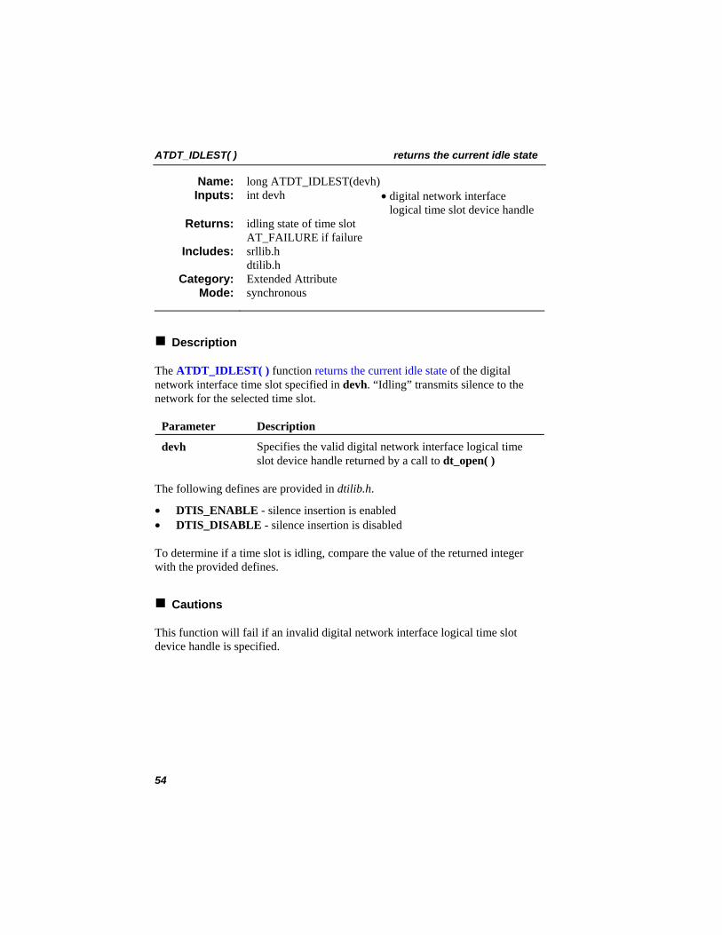
long ATDT_IDLEST(devh) Name: Inputs: int devh • digital network interface
logical time slot device handle idling state of time slot AT_FAILURE if failure
Returns:
srllib.h dtilib.h
Includes:
Extended Attribute Category: synchronous Mode:
Description
The ATDT_IDLEST( ) function returns the current idle state of the digital network interface time slot specified in devh. “Idling” transmits silence to the network for the selected time slot.
Parameter Description
devh Specifies the valid digital network interface logical time slot device handle returned by a call to dt_open( )
The following defines are provided in dtilib.h.
• DTIS_ENABLE - silence insertion is enabled • DTIS_DISABLE - silence insertion is disabled
To determine if a time slot is idling, compare the value of the returned integer with the provided defines.
Cautions
This function will fail if an invalid digital network interface logical time slot device handle is specified.
54
returns the current idle state ATDT_IDLEST( )
Example
#include <windows.h> /* For Windows applications only */ #include <srllib.h> #include <dtilib.h> #include <errno.h>
main() { int devh; /* Time slot device handle */ long mode; /* Time slot idle state mode */
/* * Open board 1 time slot 1 device */ if ( ( devh = dt_open( "dtiB1T1", 0 ) ) == -1 ) { printf( "Cannot open time slot dtiB1T1. errno = %d", errno ); exit( 1 ); }
/* * Get silence insertion mode */ if ( ( mode = ATDT_IDLEST( devh ) ) == AT_FAILURE ) { printf( "Error message = %s.",ATDV_ERRMSGP( devh ) ); exit( 1 ); }
switch ( mode ) { case DTIS_ENABLE: printf( "Time slot 1 on board 1 has silence insertion enabled\n" ); break; case DTIS_DISABLE: printf( "Time slot 1 on board 1 has silence insertion disabled\n" ); break; } . . . }
55

ATDT_IDLEST( ) returns the current idle state
Errors
If the function returns AT_FAILURE, use the SRL Standard Attribute function ATDV_LASTERR( ) to obtain the error code or use ATDV_ERRMSGP( ) to obtain a descriptive error message. See Appendix A – Dialogic® Standard Runtime Library for more information on SRL functions. The error codes returned by ATDV_LASTERR( ) are:
• EDT_BADBRDERR - digital network interface missing or defective • EDT_BADCMDERR - invalid command parameter to driver • EDT_INVTS - invalid digital network interface logical time slot device
handle • EDT_INVMSG - invalid message • EDT_NOMEMERR - cannot map or allocate memory in driver • EDT_RANGERR - bad/overlapping physical memory range • EDT_SIZEERR - message too big or too small • EDT_SKIPRPLYERR - a required reply was skipped • EDT_SYSTEM - system error - check the global variable errno for more
information about the error • EDT_TMOERR - timed out waiting for reply from firmware
Error defines can be found in the file dtilib.h.
See Also
• dt_setidle( )
56
returns the version of the EPROM ATDT_ROMVER( )
long ATDT_ROMVER(devh) Name: Inputs: int devh • digital network interface
logical board device handle version of EPROM installed on digital network interface device AT_FAILURE if function fails
Returns:
srllib.h dtilib.h
Includes:
Extended Attribute Category: synchronous Mode:
Description
The ATDT_ROMVER( ) function returns the version of the EPROM that is installed on the digital network interface device specified in devh. This number is returned in the standard version numbering format. This function is not available on Dialogic® DIALOG/HD Boards.
Parameter Description
devh Specifies the valid digital network interface logical board device handle returned by a call to dt_open( ).
Version Numbering
A version number consists of two parts that provide:
1. The release TYPE (Example: Production or Beta)
2. The release NUMBER, which consists of different elements depending on the type of release, for example:
• 1.00 Production • 1.00 Beta 5
NOTE: The examples above are shown in the convention used to display version numbers.
This function returns the version number as a long integer (32 bits) in BCD (binary coded decimal) format.
57
ATDT_ROMVER( ) returns the version of the EPROM
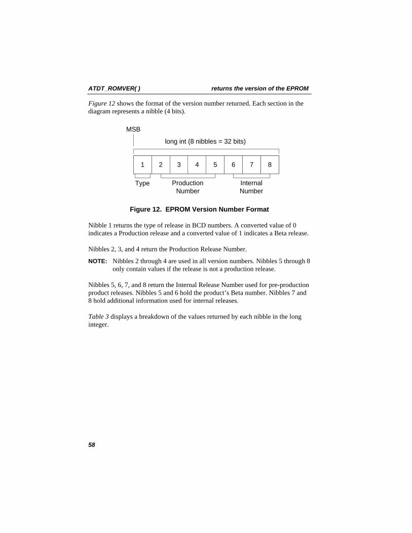
Figure 12 shows the format of the version number returned. Each section in the diagram represents a nibble (4 bits).
1 2 876543
long int (8 nibbles = 32 bits)
MSB
Type ProductionNumber
InternalNumber
Figure 12. EPROM Version Number Format
Nibble 1 returns the type of release in BCD numbers. A converted value of 0 indicates a Production release and a converted value of 1 indicates a Beta release.
Nibbles 2, 3, and 4 return the Production Release Number.
NOTE: Nibbles 2 through 4 are used in all version numbers. Nibbles 5 through 8 only contain values if the release is not a production release.
Nibbles 5, 6, 7, and 8 return the Internal Release Number used for pre-production product releases. Nibbles 5 and 6 hold the product’s Beta number. Nibbles 7 and 8 hold additional information used for internal releases.
Table 3 displays a breakdown of the values returned by each nibble in the long integer.
58
returns the version of the EPROM ATDT_ROMVER( )
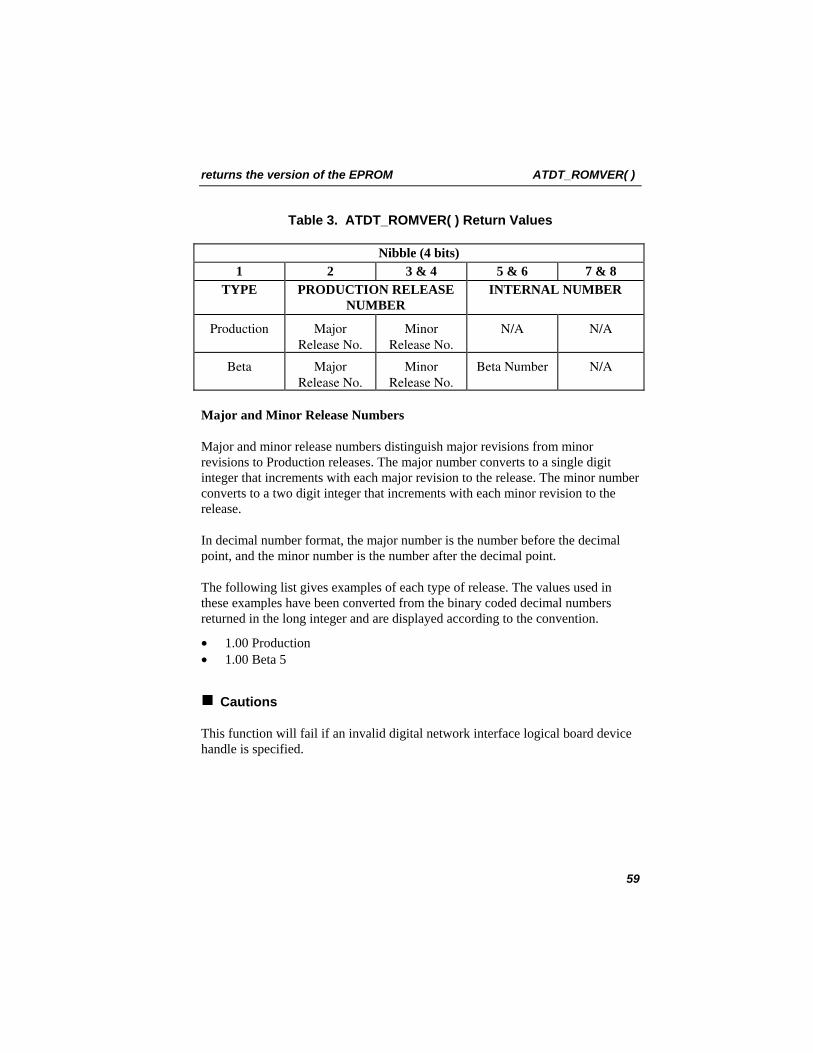
Table 3. ATDT_ROMVER( ) Return Values
Nibble (4 bits) 1 2 3 & 4 5 & 6 7 & 8
TYPE PRODUCTION RELEASE NUMBER
INTERNAL NUMBER
Production Major Release No.
Minor Release No.
N/A N/A
Beta Major Release No.
Minor Release No.
Beta Number N/A
Major and Minor Release Numbers
Major and minor release numbers distinguish major revisions from minor revisions to Production releases. The major number converts to a single digit integer that increments with each major revision to the release. The minor number converts to a two digit integer that increments with each minor revision to the release.
In decimal number format, the major number is the number before the decimal point, and the minor number is the number after the decimal point.
The following list gives examples of each type of release. The values used in these examples have been converted from the binary coded decimal numbers returned in the long integer and are displayed according to the convention.
• 1.00 Production • 1.00 Beta 5
Cautions
This function will fail if an invalid digital network interface logical board device handle is specified.
59
ATDT_ROMVER( ) returns the version of the EPROM
Example
#include <windows.h> /* For Windows applications only */ #include <srllib.h> #include <dtilib.h> #include <errno.h>
main() { int devh; /* Board device handle */ long version; /* Version number of EPROM */
/* * Open board 1 device */ if ( ( devh = dt_open( "dtiB1", 0 ) ) == -1 ) { printf( "Cannot open board dtiB1. errno = %d", errno ); exit( 1 ); }
/* * Get the version number of the EPROM */ version = ATDT_ROMVER( devh ); if ( version == AT_FAILURE ) { printf( "Error message = %s.",ATDV_ERRMSGP( devh ) ); exit( 1 ); }
/* * Display it */ printf( "DTI/2xx EPROM version number is %d.%02x\n", (int)((version>>24)&0x0F), ((version >>16)&0xFF) ); . . . }
60
returns the version of the EPROM ATDT_ROMVER( )
Errors
If the function returns AT_FAILURE, use the SRL Standard Attribute function ATDV_LASTERR( ) to obtain the error code or use ATDV_ERRMSGP( ) to obtain a descriptive error message. See Appendix A – Dialogic® Standard Runtime Library for more information on SRL functions. The error codes returned by ATDV_LASTERR( ) are:
• EDT_BADBRDERR - digital network interface missing or defective • EDT_BADCMDERR - invalid command parameter to driver • EDT_INVBD - invalid digital network interface logical board device handle • EDT_NOMEMERR - cannot map or allocate memory in driver • EDT_RANGERR - bad/overlapping physical memory range • EDT_SIZEERR - message too big or too small • EDT_SKIPRPLYERR - a required reply was skipped • EDT_SYSTEM - system error - check the global variable errno for more
information about the error • EDT_TMOERR - timed out waiting for reply from firmware
Error defines can be found in the file dtilib.h.
See Also
• ATDT_DNLDVER( )
61
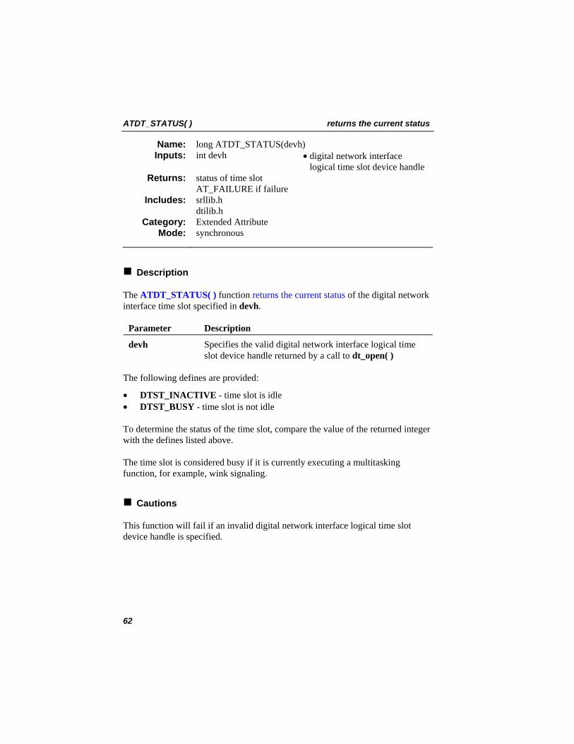
ATDT_STATUS( ) returns the current status
long ATDT_STATUS(devh) Name: Inputs: int devh • digital network interface
logical time slot device handle status of time slot AT_FAILURE if failure
Returns:
srllib.h dtilib.h
Includes:
Extended Attribute Category: synchronous Mode:
Description
The ATDT_STATUS( ) function returns the current status of the digital network interface time slot specified in devh.
Parameter Description
devh Specifies the valid digital network interface logical time slot device handle returned by a call to dt_open( )
The following defines are provided:
• DTST_INACTIVE - time slot is idle • DTST_BUSY - time slot is not idle
To determine the status of the time slot, compare the value of the returned integer with the defines listed above.
The time slot is considered busy if it is currently executing a multitasking function, for example, wink signaling.
Cautions
This function will fail if an invalid digital network interface logical time slot device handle is specified.
62
returns the current status ATDT_STATUS( )
Example
#include <windows.h> /* For Windows applications only */ #include <srllib.h> #include <dtilib.h> #include <errno.h>
main() { int devh; /* Time slot device handle */ long mode; /* Current status of time slot */
/* * Open board 1 time slot 1 device */ if ( ( devh = dt_open( "dtiB1T1", 0 ) ) == -1 ) { printf( "Cannot open time slot dtiB1T1. errno = %d", errno ); exit( 1 ); }
/* * Get current wink status of time slot */ if ( ( mode = ATDT_STATUS( devh ) ) == AT_FAILURE ) { printf( "Error message = %s.", ATDV_ERRMSGP( devh ) ); exit( 1 ); }
/* * Display it */ switch ( mode ) { case DTST_INACTIVE: printf( "Time slot 1 on board 1 is idle\n" ); break; case DTST_BUSY: printf( "Time slot 1 on board 1 is busy\n" ); break; } . . . }
63
ATDT_STATUS( ) returns the current status
Errors
If the function returns AT_FAILURE, use the SRL Standard Attribute function ATDV_LASTERR( ) to obtain the error code or use ATDV_ERRMSGP( ) to obtain a descriptive error message. See Appendix A – Dialogic® Standard Runtime Library for more information on SRL functions. The error codes returned by ATDV_LASTERR( ) are:
• EDT_BADBRDERR - digital network interface missing or defective • EDT_BADCMDERR - invalid command parameter to driver • EDT_INVMSG - invalid message • EDT_INVTS - invalid digital network interface logical time slot device
handle • EDT_NOMEMERR - cannot map or allocate memory in driver • EDT_RANGERR - bad/overlapping physical memory range • EDT_SIZEERR - message too big or too small • EDT_SKIPRPLYERR - a required reply was skipped • EDT_SYSTEM - system error - check the global variable errno for more
information about the error • EDT_TMOERR - timed out waiting for reply from firmware
Error defines can be found in the file dtilib.h.
See Also
• dt_xmitwink( )
64
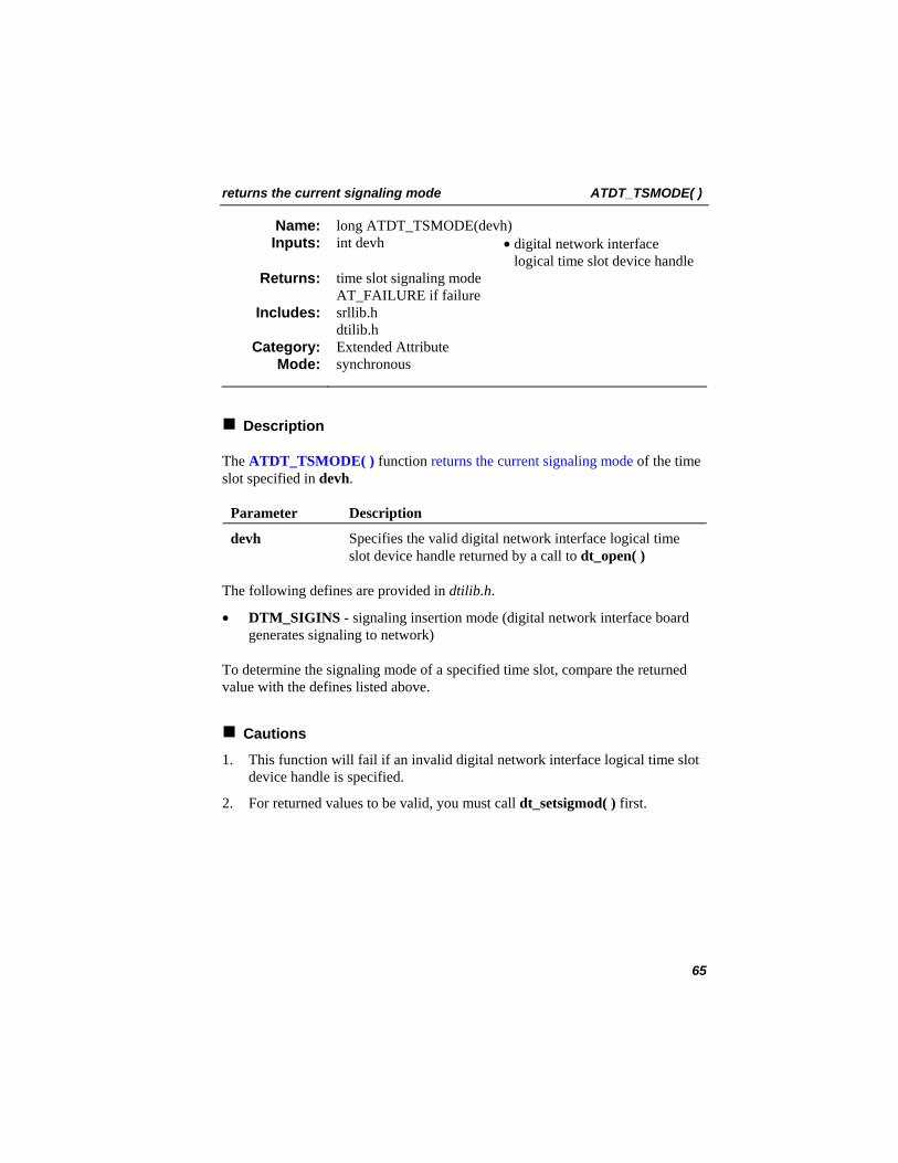
returns the current signaling mode ATDT_TSMODE( )
long ATDT_TSMODE(devh) Name: Inputs: int devh • digital network interface
logical time slot device handle time slot signaling mode AT_FAILURE if failure
Returns:
srllib.h dtilib.h
Includes:
Extended Attribute Category: synchronous Mode:
Description
The ATDT_TSMODE( ) function returns the current signaling mode of the time slot specified in devh.
Parameter Description
devh Specifies the valid digital network interface logical time slot device handle returned by a call to dt_open( )
The following defines are provided in dtilib.h.
• DTM_SIGINS - signaling insertion mode (digital network interface board generates signaling to network)
To determine the signaling mode of a specified time slot, compare the returned value with the defines listed above.
Cautions
1. This function will fail if an invalid digital network interface logical time slot device handle is specified.
2. For returned values to be valid, you must call dt_setsigmod( ) first.
65
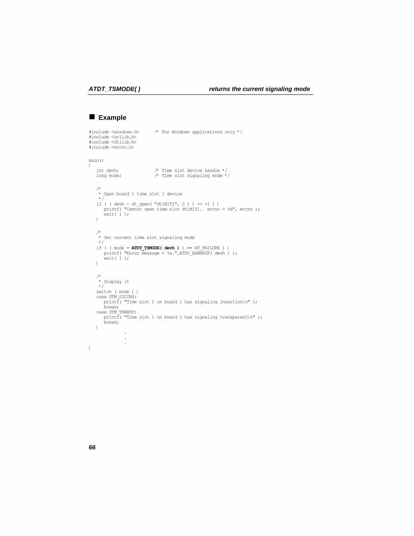
ATDT_TSMODE( ) returns the current signaling mode
Example
#include <windows.h> /* For Windows applications only */ #include <srllib.h> #include <dtilib.h> #include <errno.h>
main() { int devh; /* Time slot device handle */ long mode; /* Time slot signaling mode */
/* * Open board 1 time slot 1 device */ if ( ( devh = dt_open( "dtiB1T1", 0 ) ) == -1 ) { printf( "Cannot open time slot dtiB1T1. errno = %d", errno ); exit( 1 ); }
/* * Get current time slot signaling mode */ if ( ( mode = ATDT_TSMODE( devh ) ) == AT_FAILURE ) { printf( "Error message = %s.",ATDV_ERRMSGP( devh ) ); exit( 1 ); }
/* * Display it */ switch ( mode ) { case DTM_SIGINS: printf( "Time slot 1 on board 1 has signaling insertion\n" ); break; case DTM_TRANSP: printf( "Time slot 1 on board 1 has signaling transparent\n" ); break; } . . . }
66
returns the current signaling mode ATDT_TSMODE( )
Errors
If the function returns AT_FAILURE, use the SRL Standard Attribute function ATDV_LASTERR( ) to obtain the error code or use ATDV_ERRMSGP( ) to obtain a descriptive error message. See Appendix A – Dialogic® Standard Runtime Library for more information on SRL functions. The error codes returned by ATDV_LASTERR( ) are:
• EDT_BADBRDERR - digital network interface missing or defective • EDT_BADCMDERR - invalid command parameter to driver • EDT_INVTS - invalid digital network interface logical time slot device
handle • EDT_NOMEMERR - cannot map or allocate memory in driver • EDT_RANGERR - bad/overlapping physical memory range • EDT_SIZEERR - message too big or too small • EDT_SKIPRPLYERR - a required reply was skipped • EDT_SYSTEM - system error - check the global variable errno for more
information about the error • EDT_TMOERR - timed out waiting for reply from firmware
Error defines can be found in the file dtilib.h.
See Also
• ATDT_BDSGBIT( ) • ATDT_BDMODE( ) • dt_setsigmod( ) • dt_settssig( )
67
ATDT_TSSGBIT( ) retrieves the current bit state
long ATDT_TSSGBIT(devh) Name: Inputs: int devh • digital network interface
logical time slot device handle state of time slot signaling bits AT_FAILURE if failure
Returns:
srllib.h dtilib.h
Includes:
Extended Attribute Category: synchronous Mode:
Description
The ATDT_TSSGBIT( ) function retrieves the current bit state of the transmit and receive signaling bits for the time slot specified by devh.
Parameter Description
devh Specifies the valid digital network interface logical time slot device handle returned by a call to dt_open( )
The returned bitmask represents the following signaling bits:
• DTSG_RCVA - “A” receive signaling bit • DTSG_RCVB - “B” receive signaling bit • DTSG_RCVC - “C” receive signaling bit (E1 only) • DTSG_RCVD - “D” receive signaling bit (E1 only) • DTSG_XMTA - “A” transmit signaling bit • DTSG_XMTB - “B” transmit signaling bit • DTSG_XMTC - “C” transmit signaling bit (E1 only) • DTSG_XMTD - “D” transmit signaling bit (E1 only)
To determine the state of the signaling bits for the specified time slot, perform a logical AND operation on the byte buffer and the defines, as demonstrated in the example below.
68
retrieves the current bit state ATDT_TSSGBIT( )
Cautions
1. This function will fail if an invalid digital network interface logical time slot device handle is specified.
2. The transmit signaling bits are only valid when the device is in signaling insertion mode.
Example
#include <windows.h> /* For Windows applications only */ #include <srllib.h> #include <dtilib.h> #include <errno.h> main() { int devh; /* Time slot device handle */ long tsbits; /* Time slot signaling bits */ int arcv, brcv, axmt, bxmt; /* Bit mask values */ /* * Open board 1 time slot 1 device */ if ( ( devh = dt_open( "dtiB1T1", 0 ) ) == -1 ) { printf( "Cannot open time slot dtiB1T1. errno = %d", errno ); exit( 1 ); } /* * Get time slot signaling bits */ tsbits = ATDT_TSSGBIT( devh ); if ( tsbits == AT_FAILURE ) { printf( "Error message = %s.",ATDV_ERRMSGP( devh ) ); exit( 1 ); } /* * Display it */ arcv = ( tsbits & DTSG_RCVA ) ? 1 : 0; brcv = ( tsbits & DTSG_RCVB ) ? 1 : 0; axmt = ( tsbits & DTSG_XMTA ) ? 1 : 0; bxmt = ( tsbits & DTSG_XMTB ) ? 1 : 0; printf( "tslot 1 arcv = %d, brcv = %d, axmt = %d, bxmt = %d\n", arcv, brcv, axmt, bxmt ); . . . }
69
ATDT_TSSGBIT( ) retrieves the current bit state
Errors
If the function returns AT_FAILURE, use the SRL Standard Attribute function ATDV_LASTERR( ) to obtain the error code or use ATDV_ERRMSGP( ) to obtain a descriptive error message. See Appendix A – Dialogic® Standard Runtime Library for more information on SRL functions. The error codes returned by ATDV_LASTERR( ) are:
• EDT_BADBRDERR - digital network interface missing or defective • EDT_BADCMDERR - invalid command parameter to driver • EDT_INVTS - invalid digital network interface logical time slot device
handle • EDT_NOMEMERR - cannot map or allocate memory in driver • EDT_RANGERR - bad/overlapping physical memory range • EDT_SIZEERR - message too big or too small • EDT_SKIPRPLYERR - a required reply was skipped • EDT_SYSTEM - system error - check the global variable errno for more
information about the error • EDT_TMOERR - timed out waiting for reply from firmware
Error defines can be found in the file dtilib.h.
See Also
• ATDT_BDSGBIT( ) • ATDT_BDMODE( ) • ATDT_TSMODE( ) • dt_setsigmod( ) • dt_settssig( )
70
decode the CAS DTI reply or event message block dt_castdecode( )
int dt_castdecode (msgp, decmsgbufp) Name: Inputs: void *msgp • pointer to encoded message
block void *decmsgbufp • pointer to destination buffer of
decoded message block 0 on success -1 on failure
Returns:
dtilib.h Includes: CAS DTI Convenience Category: synchronous Mode:
Description
The dt_castdecode( ) function is called internally by the DTI event retriever for each CAS DTI reply or event message block that occurs. Its purpose is to decode the CAS DTI reply or event message block before it is given to dt_castmgmt( ) or the application, respectively. This function is offered to localize the tasks of host system issues (i.e. byte swapping) and message formation with regards to messages that are passed across the host system bus.
The dt_castdecode( ) function takes as its first parameter a CAS DTI message block. It will use the decmsgbufp parameter to return the decoded message block. The operation of this function does not prevent msgp and decmsgbufp from being the same buffer.
Example
#include "dtilib.h" … /* * This is a code fragment demonstrating * the use of the _dt_castdecode() function. */ …
/* * Read CAS DTI message block from driver. */ …
/* * Decode the CAS DTI message block * before interrogating its contents. *
71
dt_castdecode( ) decode the CAS DTI reply or event message block
* Note: The CAS DTI message block should * not be manipulated until after this point. */ if ((n = _dt_castdecode(msgp, msgp)) == -1) { ndt_set_lasterr(devh, EDT_INVMSG); return -1; } …
Errors
This function returns -1 if it does not recognize the msg_code field the reply or event message block.
See Also
• dt_castencode( )
72
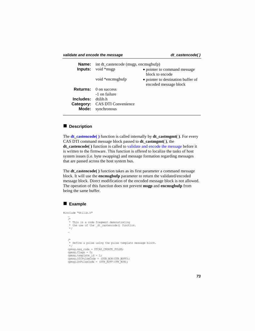
validate and encode the message dt_castencode( )
int dt_castencode (msgp, encmsgbufp) Name: Inputs: void *msgp • pointer to command message
block to encode void *encmsgbufp • pointer to destination buffer of
encoded message block 0 on success -1 on failure
Returns:
dtilib.h Includes: CAS DTI Convenience Category: synchronous Mode:
Description
The dt_castencode( ) function is called internally by dt_castmgmt( ). For every CAS DTI command message block passed to dt_castmgmt( ), the dt_castencode( ) function is called to validate and encode the message before it is written to the firmware. This function is offered to localize the tasks of host system issues (i.e. byte swapping) and message formation regarding messages that are passed across the host system bus.
The dt_castencode( ) function takes as its first parameter a command message block. It will use the encmsgbufp parameter to return the validated/encoded message block. Direct modification of the encoded message block is not allowed. The operation of this function does not prevent msgp and encmsgbufp from being the same buffer.
Example
#include "dtilib.h" … /* * This is a code fragment demonstrating * the use of the _dt_castencode() function. */ …
/* * Define a pulse using the pulse template message block. */ cpmsg.msg_code = DTCAS_CREATE_PULSE; cpmsg.flags = 0; cpmsg.template_id = 1; cpmsg.OffPulseCode = (DTB_AON|DTB_BOFF); cpmsg.OnPulseCode = (DTB_AOFF|DTB_BON);
73
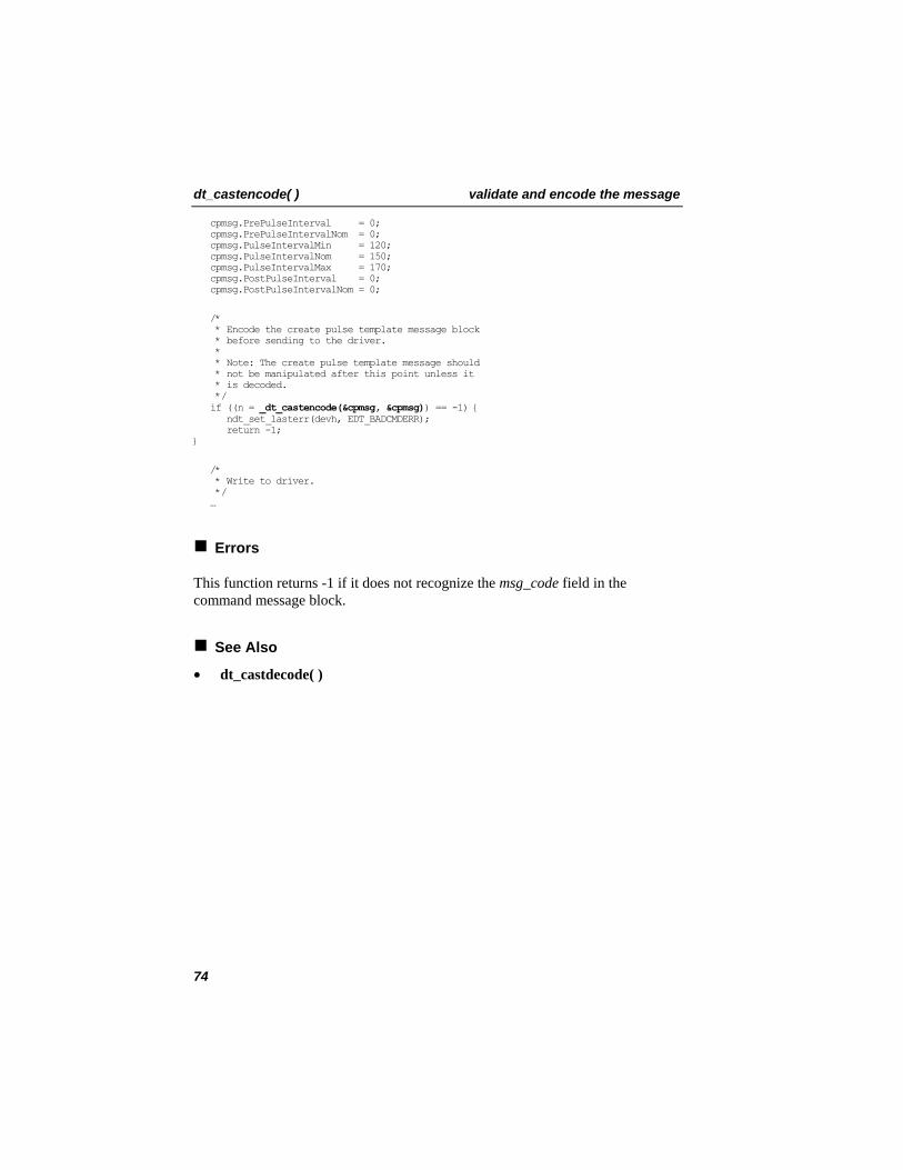
dt_castencode( ) validate and encode the message
cpmsg.PrePulseInterval = 0; cpmsg.PrePulseIntervalNom = 0; cpmsg.PulseIntervalMin = 120; cpmsg.PulseIntervalNom = 150; cpmsg.PulseIntervalMax = 170; cpmsg.PostPulseInterval = 0; cpmsg.PostPulseIntervalNom = 0;
/* * Encode the create pulse template message block * before sending to the driver. * * Note: The create pulse template message should * not be manipulated after this point unless it * is decoded. */ if ((n = _dt_castencode(&cpmsg, &cpmsg)) == -1) { ndt_set_lasterr(devh, EDT_BADCMDERR); return -1; }
/* * Write to driver. */ …
Errors
This function returns -1 if it does not recognize the msg_code field in the command message block.
See Also
• dt_castdecode( )
74
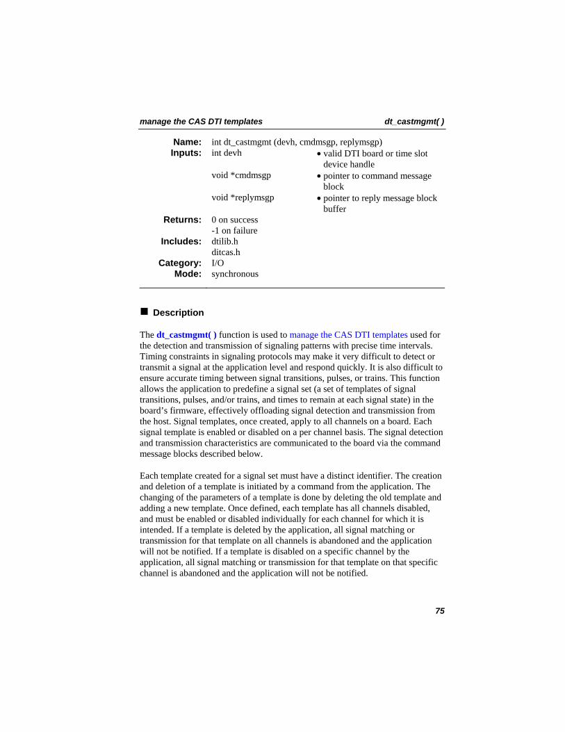
manage the CAS DTI templates dt_castmgmt( )
int dt_castmgmt (devh, cmdmsgp, replymsgp) Name: Inputs: int devh • valid DTI board or time slot
device handle void *cmdmsgp • pointer to command message
block void *replymsgp • pointer to reply message block
buffer 0 on success -1 on failure
Returns:
dtilib.h ditcas.h
Includes:
I/O Category: synchronous Mode:
Description
The dt_castmgmt( ) function is used to manage the CAS DTI templates used for the detection and transmission of signaling patterns with precise time intervals. Timing constraints in signaling protocols may make it very difficult to detect or transmit a signal at the application level and respond quickly. It is also difficult to ensure accurate timing between signal transitions, pulses, or trains. This function allows the application to predefine a signal set (a set of templates of signal transitions, pulses, and/or trains, and times to remain at each signal state) in the board’s firmware, effectively offloading signal detection and transmission from the host. Signal templates, once created, apply to all channels on a board. Each signal template is enabled or disabled on a per channel basis. The signal detection and transmission characteristics are communicated to the board via the command message blocks described below.
Each template created for a signal set must have a distinct identifier. The creation and deletion of a template is initiated by a command from the application. The changing of the parameters of a template is done by deleting the old template and adding a new template. Once defined, each template has all channels disabled, and must be enabled or disabled individually for each channel for which it is intended. If a template is deleted by the application, all signal matching or transmission for that template on all channels is abandoned and the application will not be notified. If a template is disabled on a specific channel by the application, all signal matching or transmission for that template on that specific channel is abandoned and the application will not be notified.
75
dt_castmgmt( ) manage the CAS DTI templates
For signal detection, once a template is enabled on a channel, all incoming signaling changes are matched against the template on that channel. If more than one template is enabled on a channel, incoming signaling changes are matched against all templates on that channel. As soon as all the parameters on a template(s) are matched, an unsolicited event (DTEV_CASTEVT) is sent to the application. The event data contains the identifier of the template that was detected. The firmware will send the event each time a transition, pulse, or train of pulses is received and validated.
For signal transmission, once a template is defined and enabled, an application can transmit signals matching that template using a subcommand DTCAS_TRANSMIT_TEMPLATE. The board immediately acknowledges the send command with DTCAS_TRANSMIT_TEMPLATE_COMPLETE. The application receives an unsolicited event (DTEV_CASSENDENDEVT) after send command succeeds.
Signal detection or transmission is terminated when any of the following conditions are satisfied:
• The template is disabled or deleted. • A change in the detected signal is detected.
This function operates in the synchronous (blocking) mode; however, signal detection or transmission, once enabled, occurs asynchronously. All data structures used for creating a template, deleting a template, enabling a template, disabling a template, detecting a signal, and transmitting a signal are defined in dticas.h.
Parameter Description
devh Specifies the valid board or time slot device handle returned by the call to dt_open( ). The type of handle depends on the cmdmsgp argument.
cmdmsgp Points to the command message block. Descriptions of valid command message blocks are listed in Appendix B - Message Blocks. Although the number of fields and their meaning are different for each command message block, they all contain one or more of the data types described in the Common Data Types table below.
76
manage the CAS DTI templates dt_castmgmt( )
Parameter
Description
replymsgp Points to the reply message block buffer supplied by the application. If the function returns 0, this buffer is filled with the reply message block. Descriptions of the reply message block expected by each command are listed in Appendix B - Message Blocks. Although the number of fields and their meaning are different for each reply message block, they all contain one or more of the data types described in the Common Data Types table below.
WARNING
The application is responsible for allocating a reply message block buffer of sufficient length.
If event handling is set up properly for your application, the sr_getevttype( ) function included in the SRL will return DTEV_CASTEVT when a signal pattern match occurs, and DTEV_CASSENDENDEVT when signal transmission is complete. The DTEV_CASTEVT and DTEV_CASSENDENDEVT event blocks are described in Appendix B - Message Blocks.
Although each message block is different, they all contain one or more of the following data types; however, there are three fields that are common to each parameter as follows:
Table 4. Common Data Types
template_id A template identifier that is a 2-byte quantity with no implicit value or order. It is used to identify the template in recognition events and to select the template in transmission commands. The application is free to use it for any unique identifier. However, it is recommended that the following convention be used: The 2-byte template IDs should consist of the high byte being a protocol number and the low byte being the template “meaning” (1=idle, 2=ring, 3=seize, etc.).
77
dt_castmgmt( ) manage the CAS DTI templates
prefixCode The signal pattern for matching and setting templates. This is a bit pattern that represents the signaling bits, and is used as a building block to specify templates. This parameter is similar to the dt_settssigsim( ) bitmask. The prefixCode can be 0 or a logical OR of one or more of the following values:
• DTB_AON - “A” signaling bit on • DTB_AOFF - “A” signaling bit off • DTB_BON - “B” signaling bit on • DTB_BOFF - “B” signaling bit off • DTB_CON - “C” signaling bit on (E1 only) • DTB_COFF - “C” signaling bit off (E1 only) • DTB_DON - “D” signaling bit on (E1 only) • DTB_DOFF - “D” signaling bit off (E1 only)
NOTE: It is incorrect to OR ON and OFF states for the same signaling bit, i.e., it is incorrect to OR DTB_AON and DTB_AOFF. The ON state will be the one matched.
prefixInterval The time interval. Time intervals are specified in units of 1 ms; however, due to the internal clock mechanism, this value may vary ±5 ms. The maximum value that can be specified is 63 seconds.
Cautions
1. The dt_settssigsim( ) function must be used to set the state of the channel's signaling bits prior to sending any CAS templates via a call to dt_castmgmt( ). The user must set the channel’s signaling bits to the state specified in the PreTransCode parameter value prior to sending a transition or to the OffPulseCode parameter value when sending a pulse or train. The user must also ensure that the pattern is transmitted for the amount of time specified by the PreTransInterval, PrePulseInterval, or PreTrainInterval parameter of the DTCAS_CREATE_TRANSITION, DTCAS_CREATE_PULSE, or DTCAS_CREATE_TRAIN command message blocks, respectively.
2. This function will fail under the following conditions: • An invalid device handle is specified.
78
manage the CAS DTI templates dt_castmgmt( )
• Signaling insertion is not enabled; the time slot must be in signaling insertion mode before this function is called. Signaling insertion mode is enabled using the dt_setsigmod( ) function.
• An application initiates a transmit command before the completion of a progressing transmission.
Example
// This program uses a D/480 or D/600 to demonstrate how CAS templates work.
#include "stdafx.h" #include <stdio.h> #include <errno.h> #include "srllib.h" #include "dtilib.h"
#include <windows.h> #include <winbase.h> #include <stdio.h> #include <process.h> #include <stddef.h> #include <stdlib.h> #include <string.h> #include <conio.h>
#define USEREVT_KEYBOARD 1 /*User defined keyboard event */
int Kbhit_flag = 0; void CheckKey( void *dummy ); int process(int,long);
int main(int argc, char* argv[]) {
int srlmode,x; int devh, devh2; /* DTI board device descriptor */ int tsdevh, tsdevh2; /* DTI channel device descriptor */ DTCAS_CREATE_TRAIN_MSG cpmsg; /* Create train template message */ DTCAS_REPLY_MSG cpcmsg; /* Reply buffer for Train template complete message */ DTCAS_ENA_DIS_TEMPLATE_MSG etmsg; /* Enable template message */ DTCAS_REPLY_MSG etcmsg; /* Reply buffer for enable template complete message */ DTCAS_TRANSMIT_MSG tmsg; /*Transmit train template message*/ DTCAS_REPLY_MSG tcmsg; /* Reply buffer for Train template transmit complete message */ DTCAS_DELETE_TEMPLATE_MSG dmsg; /*Delete train template message*/ DTCAS_REPLY_MSG dcmsg; /* Reply buffer for delete train template complete message */ int evtdev; long evttype;
/* Launch CheckKey thread to check for terminating keystroke. */ _beginthread( CheckKey, 0, NULL );
79
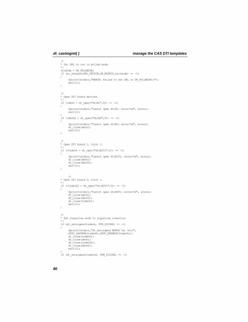
dt_castmgmt( ) manage the CAS DTI templates
/* * Set SRL to run in polled mode. */ srlmode = SR_POLLMODE; if (sr_setparm(SRL_DEVICE,SR_MODEID,&srlmode) == -1) { fprintf(stderr,"ERROR: Failed to set SRL in SR_POLLMODE\n"); exit(1); }
/* * Open DTI board devices. */ if ((devh = dt_open("dtiB1",0)) == -1) { fprintf(stderr,"Cannot open dtiB1: error=%d", errno); exit(1); } if ((devh2 = dt_open("dtiB2",0)) == -1) { fprintf(stderr,"Cannot open dtiB2: error=%d", errno); dt_close(devh); exit(1); }
/* * Open DTI board 1, tslot 1. */ if ((tsdevh = dt_open("dtiB1T1",0)) == -1) { fprintf(stderr,"Cannot open dtiB1T1: errno=%d", errno); dt_close(devh); dt_close(devh2); exit(1); }
/* * Open DTI board 2, tslot 1. */ if ((tsdevh2 = dt_open("dtiB2T1",0)) == -1) { fprintf(stderr,"Cannot open dtiB2T1: errno=%d", errno); dt_close(devh); dt_close(devh2); dt_close(tsdevh); exit(1); }
/* * Set signaling mode to signaling insertion */ if (dt_setsigmod(tsdevh, DTM_SIGINS) == -1) { fprintf(stderr,"dt_setsigmod ERROR %d: %s\n", ATDV_LASTERR(tsdevh),ATDV_ERRMSGP(tsdevh)); dt_close(tsdevh); dt_close(devh); dt_close(tsdevh2); dt_close(devh2); exit(1); } if (dt_setsigmod(tsdevh2, DTM_SIGINS) == -1)
80
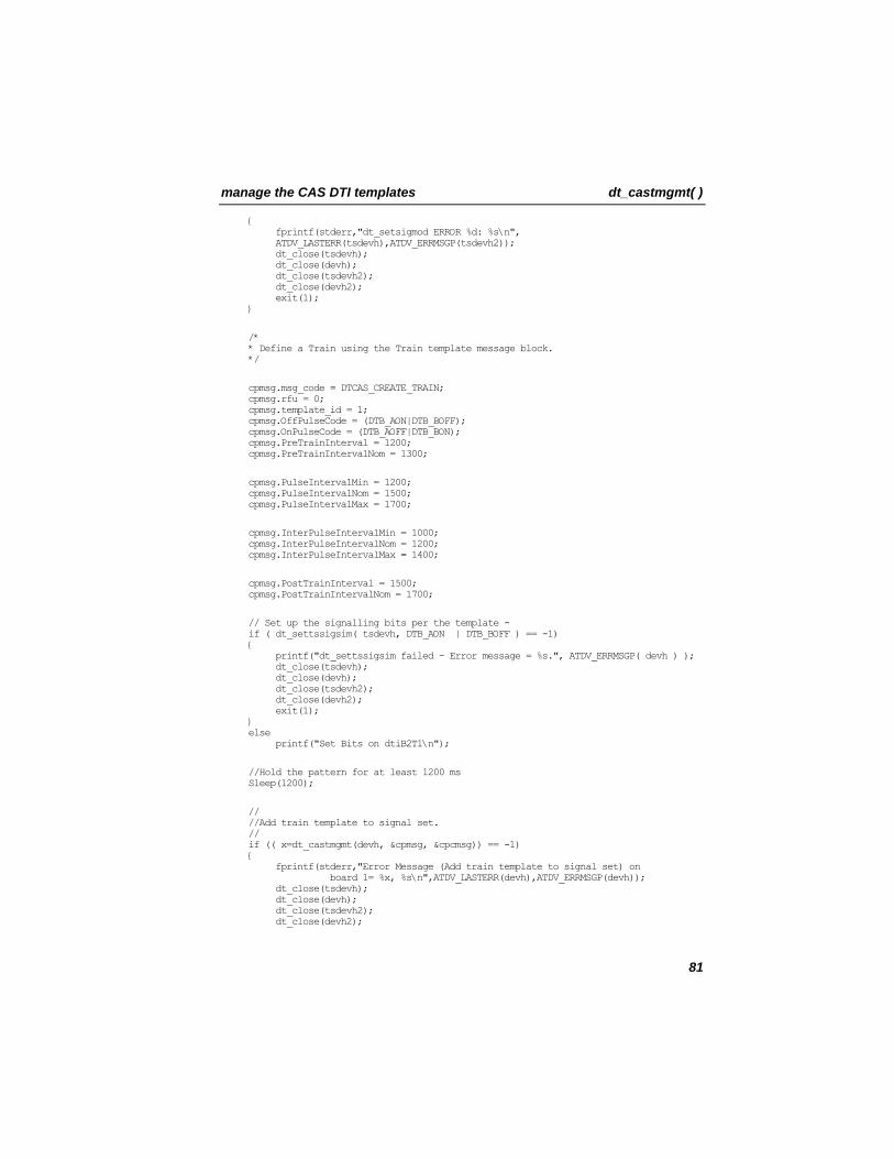
manage the CAS DTI templates dt_castmgmt( )
{ fprintf(stderr,"dt_setsigmod ERROR %d: %s\n", ATDV_LASTERR(tsdevh),ATDV_ERRMSGP(tsdevh2)); dt_close(tsdevh); dt_close(devh); dt_close(tsdevh2); dt_close(devh2); exit(1); }
/* * Define a Train using the Train template message block. */
cpmsg.msg_code = DTCAS_CREATE_TRAIN; cpmsg.rfu = 0; cpmsg.template_id = 1; cpmsg.OffPulseCode = (DTB_AON|DTB_BOFF); cpmsg.OnPulseCode = (DTB_AOFF|DTB_BON); cpmsg.PreTrainInterval = 1200; cpmsg.PreTrainIntervalNom = 1300;
cpmsg.PulseIntervalMin = 1200; cpmsg.PulseIntervalNom = 1500; cpmsg.PulseIntervalMax = 1700;
cpmsg.InterPulseIntervalMin = 1000; cpmsg.InterPulseIntervalNom = 1200; cpmsg.InterPulseIntervalMax = 1400;
cpmsg.PostTrainInterval = 1500; cpmsg.PostTrainIntervalNom = 1700;
// Set up the signalling bits per the template - if ( dt_settssigsim( tsdevh, DTB_AON | DTB_BOFF ) == -1) { printf("dt_settssigsim failed - Error message = %s.", ATDV_ERRMSGP( devh ) ); dt_close(tsdevh); dt_close(devh); dt_close(tsdevh2); dt_close(devh2); exit(1); } else printf("Set Bits on dtiB2T1\n");
//Hold the pattern for at least 1200 ms Sleep(1200);
// //Add train template to signal set. // if (( x=dt_castmgmt(devh, &cpmsg, &cpcmsg)) == -1) { fprintf(stderr,"Error Message (Add train template to signal set) on board 1= %x, %s\n",ATDV_LASTERR(devh),ATDV_ERRMSGP(devh)); dt_close(tsdevh); dt_close(devh); dt_close(tsdevh2); dt_close(devh2);
81
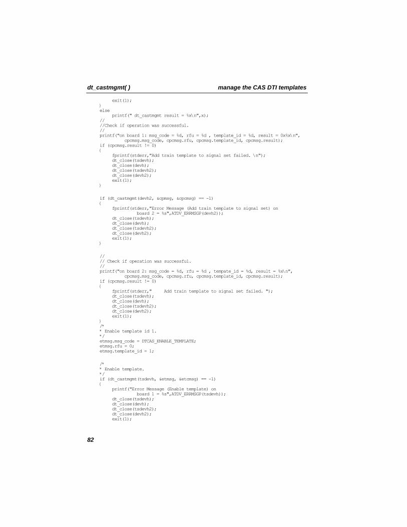
dt_castmgmt( ) manage the CAS DTI templates
exit(1); } else printf(" dt_castmgmt result = %x\n",x); // //Check if operation was successful. // printf("on board 1: msg_code = %d, rfu = %d , template_id = %d, result = 0x%x\n", cpcmsg.msg_code, cpcmsg.rfu, cpcmsg.template_id, cpcmsg.result); if (cpcmsg.result != 0) { fprintf(stderr,"Add train template to signal set failed. \n"); dt_close(tsdevh); dt_close(devh); dt_close(tsdevh2); dt_close(devh2); exit(1); }
if (dt_castmgmt(devh2, &cpmsg, &cpcmsg) == -1) { fprintf(stderr,"Error Message (Add train template to signal set) on board 2 = %s",ATDV_ERRMSGP(devh2)); dt_close(tsdevh); dt_close(devh); dt_close(tsdevh2); dt_close(devh2); exit(1); }
// // Check if operation was successful. // printf("on board 2: msg_code = %d, rfu = %d , tempate_id = %d, result = %x\n", cpcmsg.msg_code, cpcmsg.rfu, cpcmsg.template_id, cpcmsg.result); if (cpcmsg.result != 0) { fprintf(stderr," Add train template to signal set failed. "); dt_close(tsdevh); dt_close(devh); dt_close(tsdevh2); dt_close(devh2); exit(1); } /* * Enable template id 1. */ etmsg.msg_code = DTCAS_ENABLE_TEMPLATE; etmsg.rfu = 0; etmsg.template_id = 1;
/* * Enable template. */ if (dt_castmgmt(tsdevh, &etmsg, &etcmsg) == -1) { printf("Error Message (Enable template) on board 1 = %s",ATDV_ERRMSGP(tsdevh)); dt_close(tsdevh); dt_close(devh); dt_close(tsdevh2); dt_close(devh2); exit(1);
82
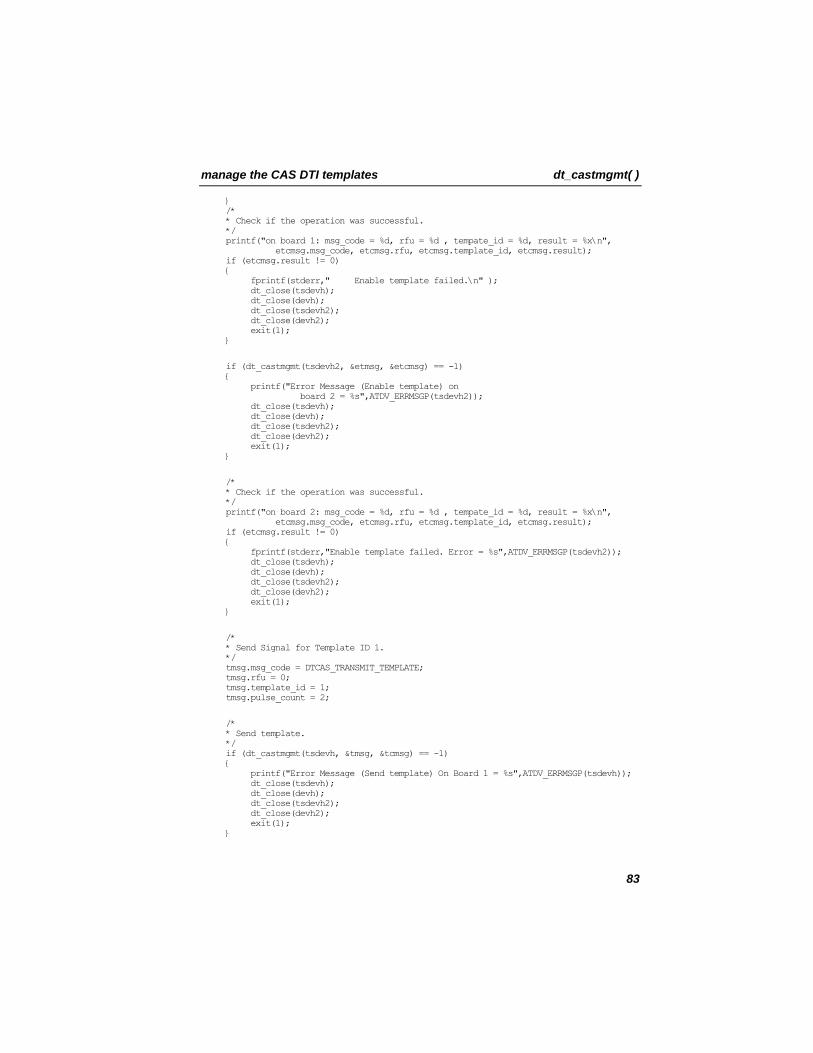
manage the CAS DTI templates dt_castmgmt( )
} /* * Check if the operation was successful. */ printf("on board 1: msg_code = %d, rfu = %d , tempate_id = %d, result = %x\n", etcmsg.msg_code, etcmsg.rfu, etcmsg.template_id, etcmsg.result); if (etcmsg.result != 0) { fprintf(stderr," Enable template failed.\n" ); dt_close(tsdevh); dt_close(devh); dt_close(tsdevh2); dt_close(devh2); exit(1); }
if (dt_castmgmt(tsdevh2, &etmsg, &etcmsg) == -1) { printf("Error Message (Enable template) on board 2 = %s",ATDV_ERRMSGP(tsdevh2)); dt_close(tsdevh); dt_close(devh); dt_close(tsdevh2); dt_close(devh2); exit(1); }
/* * Check if the operation was successful. */ printf("on board 2: msg_code = %d, rfu = %d , tempate_id = %d, result = %x\n", etcmsg.msg_code, etcmsg.rfu, etcmsg.template_id, etcmsg.result); if (etcmsg.result != 0) { fprintf(stderr,"Enable template failed. Error = %s",ATDV_ERRMSGP(tsdevh2)); dt_close(tsdevh); dt_close(devh); dt_close(tsdevh2); dt_close(devh2); exit(1); }
/* * Send Signal for Template ID 1. */ tmsg.msg_code = DTCAS_TRANSMIT_TEMPLATE; tmsg.rfu = 0; tmsg.template_id = 1; tmsg.pulse_count = 2;
/* * Send template. */ if (dt_castmgmt(tsdevh, &tmsg, &tcmsg) == -1) { printf("Error Message (Send template) On Board 1 = %s",ATDV_ERRMSGP(tsdevh)); dt_close(tsdevh); dt_close(devh); dt_close(tsdevh2); dt_close(devh2); exit(1); }
83
dt_castmgmt( ) manage the CAS DTI templates
/* * Check if the operation was successful. */ printf("on board 1: msg_code = %d, rfu = %d , tempate_id = %d, result = %x\n", tcmsg.msg_code, tcmsg.rfu, tcmsg.template_id, tcmsg.result); if (tcmsg.result != 0) { fprintf(stderr," Send template failed.\n"); dt_close(tsdevh); dt_close(devh); dt_close(tsdevh2); dt_close(devh2); exit(1); }
/*While no keyboard input, keep cycling through functions */ while (1) { /*Wait for events */ sr_waitevt(-1); evtdev = sr_getevtdev(); evttype = sr_getevttype(); if ((evtdev == SRL_DEVICE) && (evttype == USEREVT_KEYBOARD)) break; if (process(evtdev, evttype) != 0) break; }
// delete template and close ts and board dmsg.msg_code = DTCAS_DELETE_TEMPLATE; dmsg.rfu = 0; dmsg.template_id =1;//DTCAS_CLEAR_ALL_TEMPLATE
if (dt_castmgmt(tsdevh, &dmsg, &dcmsg) == -1) { printf("Error Message (deleting template) on board 1= %s",ATDV_ERRMSGP(tsdevh)); dt_close(tsdevh); dt_close(devh); dt_close(tsdevh2); dt_close(devh2); exit(1); } /* * Check if the operation was successful. */ printf("on board 1: msg_code = %d, rfu = %d , template_id = %d, result = 0x%x\n", dcmsg.msg_code, dcmsg.rfu, dcmsg.template_id, dcmsg.result); if (dcmsg.result != 0) { fprintf(stderr," Deleting template failed. \n"); dt_close(tsdevh); dt_close(devh); dt_close(tsdevh2); dt_close(devh2); exit(1); } if (dt_castmgmt(tsdevh2, &dmsg, &dcmsg) == -1) { printf("Error Message (deleting template) on board 2= %s",ATDV_ERRMSGP(tsdevh2)); dt_close(tsdevh); dt_close(devh);
84
manage the CAS DTI templates dt_castmgmt( )
dt_close(tsdevh2); dt_close(devh2); exit(1); } /* * Check if the operation was successful. */ printf("on board 2: msg_code = %d, rfu = %d , template_id = %d, result = 0x%x\n", dcmsg.msg_code, dcmsg.rfu, dcmsg.template_id, dcmsg.result); if (dcmsg.result != 0) { fprintf(stderr," Deleting template failed. \n"); dt_close(tsdevh); dt_close(devh); dt_close(tsdevh2); dt_close(devh2); exit(1); }
dt_close(tsdevh); dt_close(devh); dt_close(tsdevh2); dt_close(devh2); return 0; }
/*************************************************************************** * NAME: int process( eventdev, event ) * DESCRIPTION: Do the next function depending on the Event Received * INPUT: int eventdev; - Device on which event was received * int event; - Event being processed * OUTPUT: None * RETURNS: New Channel State * CAUTIONS: None ***************************************************************************/ int process( int tsdev, long event ) { int len = sr_getevtlen(); DTCAS_DETECTED_MSG *dmsgp1; DTCAS_END_TRANSMIT_MSG *dmsgp2;
switch ( event ) { case DTEV_CASTEVT: printf("%s: Signaling completed ", ATDV_NAMEP(tsdev)); dmsgp1 = (DTCAS_DETECTED_MSG *)sr_getevtdatap(); printf("DTEV_CASTEVT detected Template %d\t message code = %d\tResult Code = %d\n",dmsgp1->template_id,dmsgp1->msg_code,dmsgp1->result); break; case DTEV_CASSENDENDEVT: printf("%s: Signal Transmission completed ", ATDV_NAMEP(tsdev)); dmsgp2 = (DTCAS_END_TRANSMIT_MSG *)sr_getevtdatap(); printf("DTEV_CASSENDENDEVT detected Template %d\n",dmsgp2->template_id); break; default: fprintf(stderr,"%s: EVENT ERROR: Unknown event = 0x%lx\t Data Length = %d\n",ATDV_NAMEP(tsdev),sr_getevttype(),len); break; } return 0; }
85
dt_castmgmt( ) manage the CAS DTI templates
/*************************************************************************** * NAME: DWORD WINAPI keyboard_monitor( LPVOID argp ) * DESCRIPTION: Wait for keyboard input * INPUT: LPVOID argp * OUTPUT: None * RETURNS: none * CAUTIONS: None ***************************************************************************/ void CheckKey( void *dummy ) { int ch; printf("Press 'q' to quit\n"); do { ch= _getch(); if (ch=='q') { sr_putevt(SRL_DEVICE,USEREVT_KEYBOARD,0,NULL,0); } else printf("\n"); }while (ch!='q');
/* _endthread given to terminate */ _endthread(); }
Errors
If this function returns -1 to indicate failure, use ATDV_LASTERR( ) and ATDV_ERRMSGP( ) to retrieve one of the following error types.
• EDT_BADBRDERR - DTI/2xx missing or defective • EDT_BADCMDERR - invalid or undefined command to driver • EDT_DATTO - data reception timed out • EDT_FWERR - firmware returned an error • EDT_PARMERR - invalid parameter • EDT_RANGEERR - bad/overlapping physical memory range • EDT_SIZERR - message too big or too small • EDT_SKIPRPLYERR - a required reply was skipped • EDT_SYSTEM - system error - check the global variable errno for more
information about the error • EDT_TMOERR - timed out waiting for reply from firmware • EDT_INVTS - invalid time slot device handle • EDT_SIGINS - signaling insertion not enabled • EDT_INVMSG - invalid message
86
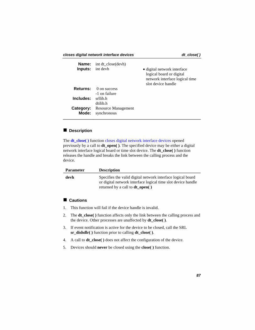
closes digital network interface devices dt_close( )
int dt_close(devh) Name: Inputs: int devh • digital network interface
logical board or digital network interface logical time slot device handle
0 on success -1 on failure
Returns:
srllib.h dtilib.h
Includes:
Resource Management Category: synchronous Mode:
Description
The dt_close( ) function closes digital network interface devices opened previously by a call to dt_open( ). The specified device may be either a digital network interface logical board or time slot device. The dt_close( ) function releases the handle and breaks the link between the calling process and the device.
Parameter Description
devh Specifies the valid digital network interface logical board or digital network interface logical time slot device handle returned by a call to dt_open( )
Cautions
1. This function will fail if the device handle is invalid.
2. The dt_close( ) function affects only the link between the calling process and the device. Other processes are unaffected by dt_close( ).
3. If event notification is active for the device to be closed, call the SRL sr_dishdlr( ) function prior to calling dt_close( ).
4. A call to dt_close( ) does not affect the configuration of the device.
5. Devices should never be closed using the close( ) function.
87
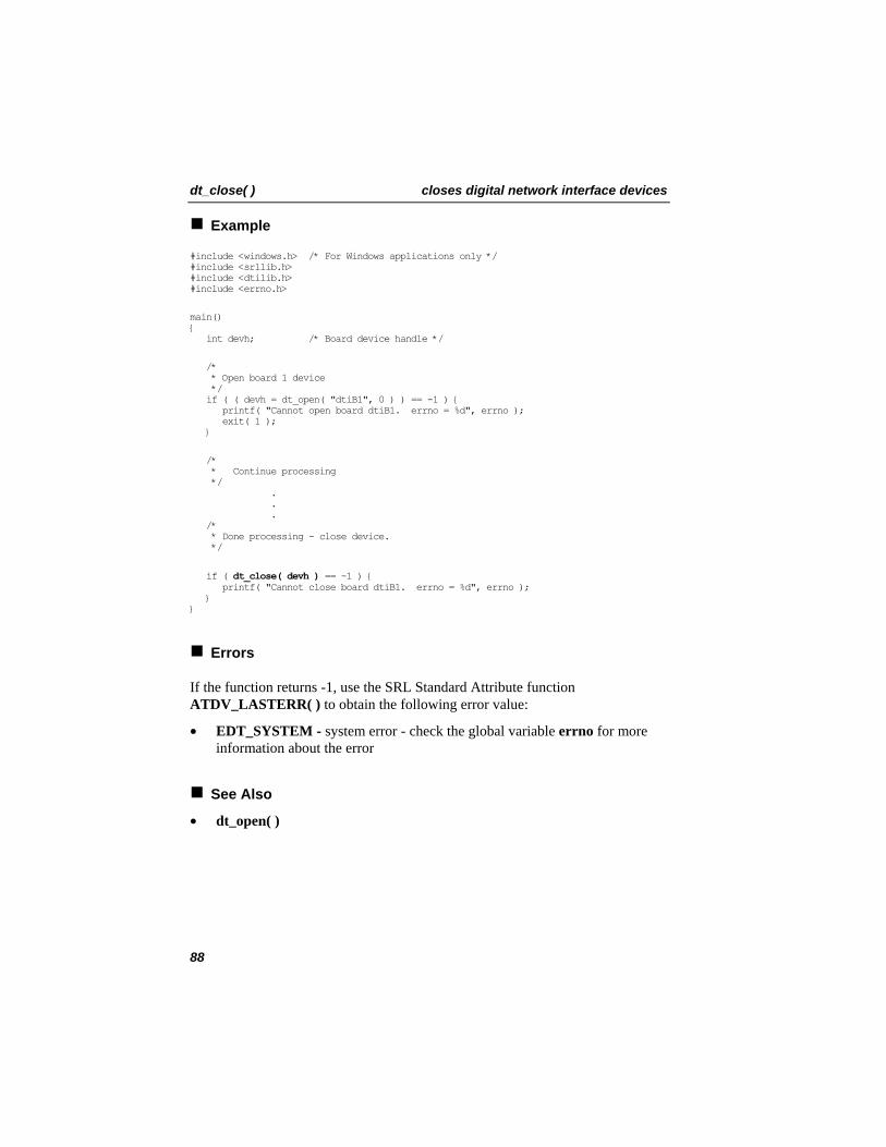
dt_close( ) closes digital network interface devices
Example
#include <windows.h> /* For Windows applications only */ #include <srllib.h> #include <dtilib.h> #include <errno.h>
main() { int devh; /* Board device handle */
/* * Open board 1 device */ if ( ( devh = dt_open( "dtiB1", 0 ) ) == -1 ) { printf( "Cannot open board dtiB1. errno = %d", errno ); exit( 1 ); }
/* * Continue processing */ . . . /* * Done processing - close device. */
if ( dt_close( devh ) == -1 ) { printf( "Cannot close board dtiB1. errno = %d", errno ); } }
Errors
If the function returns -1, use the SRL Standard Attribute function ATDV_LASTERR( ) to obtain the following error value:
• EDT_SYSTEM - system error - check the global variable errno for more information about the error
See Also
• dt_open( )
88
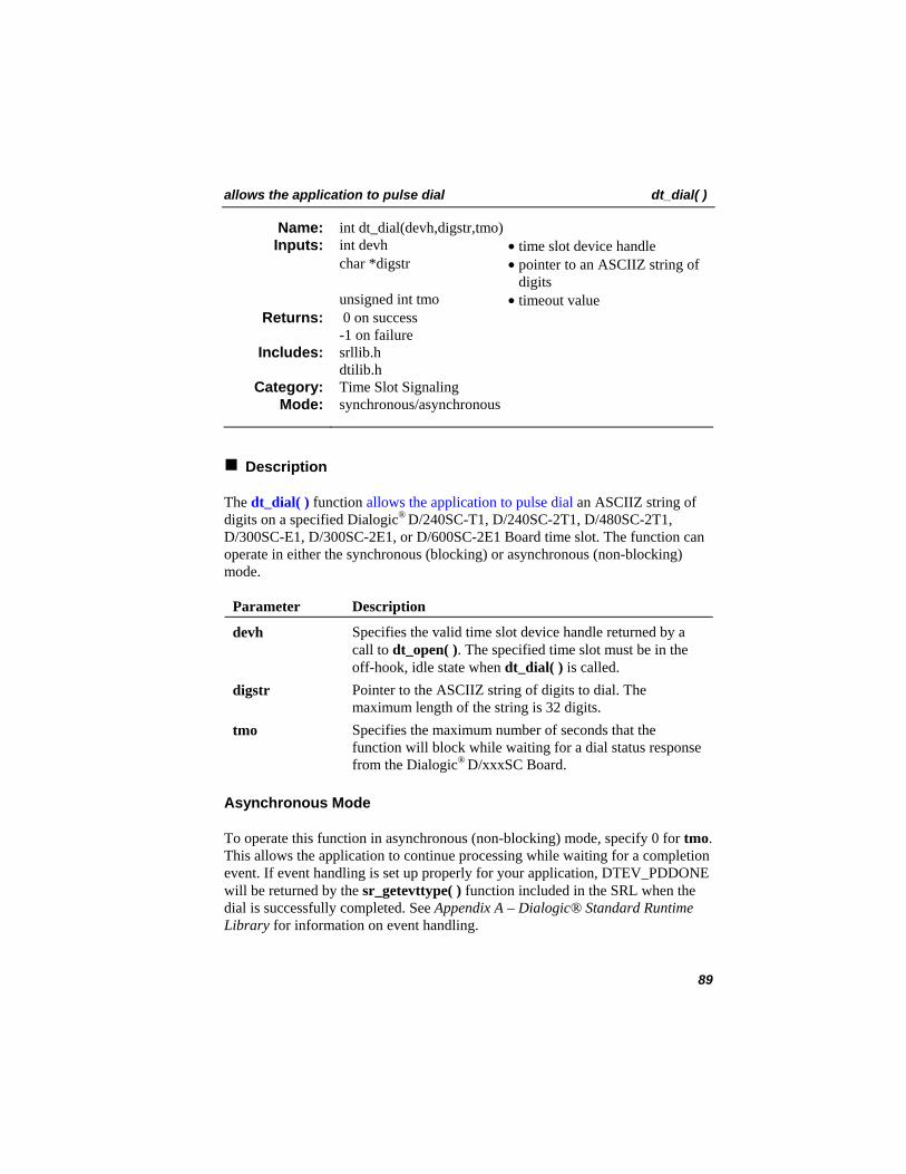
allows the application to pulse dial dt_dial( )
int dt_dial(devh,digstr,tmo) Name: Inputs: int devh • time slot device handle
char *digstr • pointer to an ASCIIZ string of digits
unsigned int tmo • timeout value 0 on success -1 on failure
Returns:
srllib.h dtilib.h
Includes:
Time Slot Signaling Category: synchronous/asynchronous Mode:
Description
The dt_dial( ) function allows the application to pulse dial an ASCIIZ string of digits on a specified Dialogic® D/240SC-T1, D/240SC-2T1, D/480SC-2T1, D/300SC-E1, D/300SC-2E1, or D/600SC-2E1 Board time slot. The function can operate in either the synchronous (blocking) or asynchronous (non-blocking) mode.
Parameter Description
devh Specifies the valid time slot device handle returned by a call to dt_open( ). The specified time slot must be in the off-hook, idle state when dt_dial( ) is called.
digstr Pointer to the ASCIIZ string of digits to dial. The maximum length of the string is 32 digits.
tmo Specifies the maximum number of seconds that the function will block while waiting for a dial status response from the Dialogic® D/xxxSC Board.
Asynchronous Mode
To operate this function in asynchronous (non-blocking) mode, specify 0 for tmo. This allows the application to continue processing while waiting for a completion event. If event handling is set up properly for your application, DTEV_PDDONE will be returned by the sr_getevttype( ) function included in the SRL when the dial is successfully completed. See Appendix A – Dialogic® Standard Runtime Library for information on event handling.
89
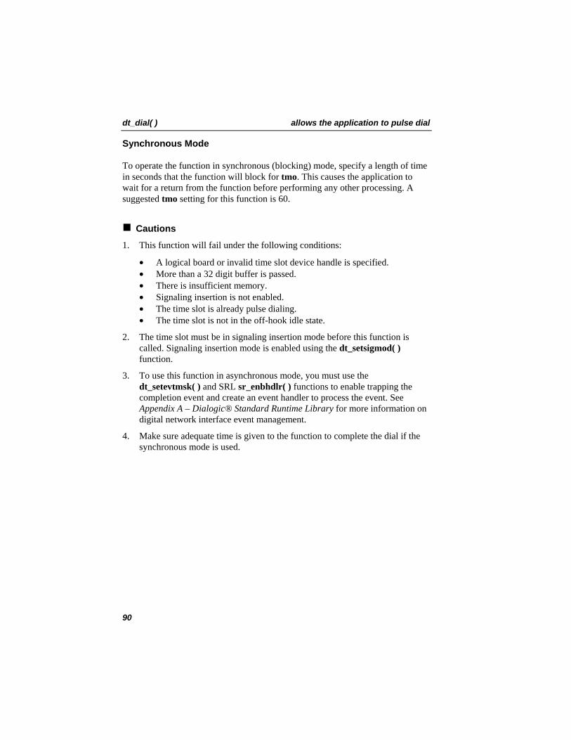
dt_dial( ) allows the application to pulse dial
Synchronous Mode
To operate the function in synchronous (blocking) mode, specify a length of time in seconds that the function will block for tmo. This causes the application to wait for a return from the function before performing any other processing. A suggested tmo setting for this function is 60.
Cautions
1. This function will fail under the following conditions:
• A logical board or invalid time slot device handle is specified. • More than a 32 digit buffer is passed. • There is insufficient memory. • Signaling insertion is not enabled. • The time slot is already pulse dialing. • The time slot is not in the off-hook idle state.
2. The time slot must be in signaling insertion mode before this function is called. Signaling insertion mode is enabled using the dt_setsigmod( ) function.
3. To use this function in asynchronous mode, you must use the dt_setevtmsk( ) and SRL sr_enbhdlr( ) functions to enable trapping the completion event and create an event handler to process the event. See Appendix A – Dialogic® Standard Runtime Library for more information on digital network interface event management.
4. Make sure adequate time is given to the function to complete the dial if the synchronous mode is used.
90
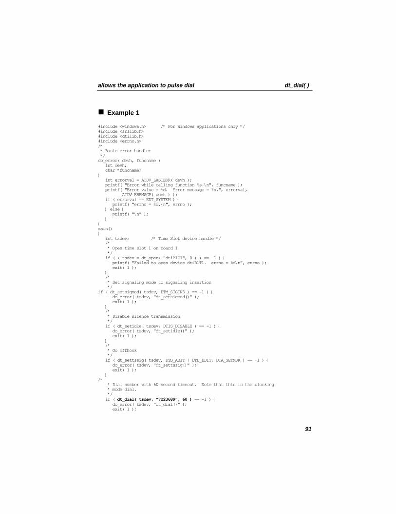
allows the application to pulse dial dt_dial( )
Example 1
#include <windows.h> /* For Windows applications only */ #include <srllib.h> #include <dtilib.h> #include <errno.h> /* * Basic error handler */ do_error( devh, funcname ) int devh; char *funcname; { int errorval = ATDV_LASTERR( devh ); printf( "Error while calling function %s.\n", funcname ); printf( "Error value = %d. Error message = %s.", errorval, ATDV_ERRMSGP( devh ) ); if ( errorval == EDT_SYSTEM ) { printf( "errno = %d.\n", errno ); } else { printf( "\n" ); } } main() { int tsdev; /* Time Slot device handle */ /* * Open time slot 1 on board 1 */ if ( ( tsdev = dt_open( "dtiB1T1", 0 ) ) == -1 ) { printf( "Failed to open device dtiB1T1. errno = %d\n", errno ); exit( 1 ); } /* * Set signaling mode to signaling insertion */ if ( dt_setsigmod( tsdev, DTM_SIGINS ) == -1 ) { do_error( tsdev, "dt_setsigmod()" ); exit( 1 ); } /* * Disable silence transmission */ if ( dt_setidle( tsdev, DTIS_DISABLE ) == -1 ) { do_error( tsdev, "dt_setidle()" ); exit( 1 ); } /* * Go offhook */ if ( dt_settssig( tsdev, DTB_ABIT | DTB_BBIT, DTA_SETMSK ) == -1 ) { do_error( tsdev, "dt_settssig()" ); exit( 1 ); } /* * Dial number with 60 second timeout. Note that this is the blocking * mode dial. */ if ( dt_dial( tsdev, "7223689", 60 ) == -1 ) { do_error( tsdev, "dt_dial()" ); exit( 1 );
91
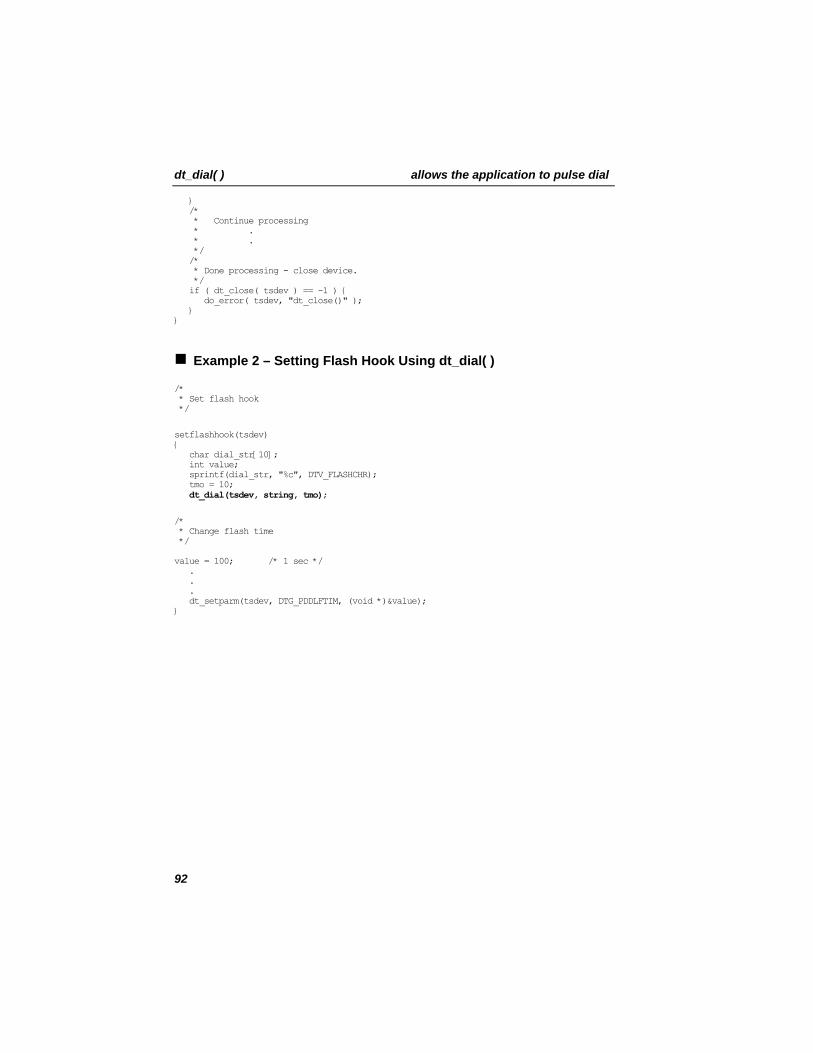
dt_dial( ) allows the application to pulse dial
} /* * Continue processing * . * . */ /* * Done processing - close device. */ if ( dt_close( tsdev ) == -1 ) { do_error( tsdev, "dt_close()" ); } }
Example 2 – Setting Flash Hook Using dt_dial( )
/* * Set flash hook */
setflashhook(tsdev) { char dial_str[10]; int value; sprintf(dial_str, "%c", DTV_FLASHCHR); tmo = 10; dt_dial(tsdev, string, tmo);
/* * Change flash time */ value = 100; /* 1 sec */ . . . dt_setparm(tsdev, DTG_PDDLFTIM, (void *)&value); }
92
allows the application to pulse dial dt_dial( )
Errors
If the function returns -1, use the SRL Standard Attribute function ATDV_LASTERR( ) to obtain the error code. See Appendix A – Dialogic® Standard Runtime Library for more information on SRL functions. The error codes returned by ATDV_LASTERR are:
• EDT_BADBRDERR - digital network interface missing or defective • EDT_BADCMDERR - invalid or undefined command to driver • EDT_DATTO - data reception timed out • EDT_FWERR - firmware returned an error • EDT_NOMEMERR - cannot map or allocate memory in driver • EDT_PARAMERR - invalid parameter • EDT_RANGEERR - bad/overlapping physical memory range • EDT_SIZERR - message too big or too small • EDT_SKIPRPLYERR - a required reply was skipped • EDT_SYSTEM - system error - check the global variable errno for more
information about the error • EDT_TMOERR - timed out waiting for reply from firmware • EDT_INVTS - invalid time slot device handle • EDT_SIGINS - signaling insertion not enabled • EDT_TSBSY - time slot is busy • EDT_PDOFFHK - not in off-hook idle state • EDT_PDSIG - cannot disable insertion when pulse dialing
Error defines can be found in the file dtilib.h.
See Also
In the Dialogic® Voice API Library Reference:
• dx_dial( )
93
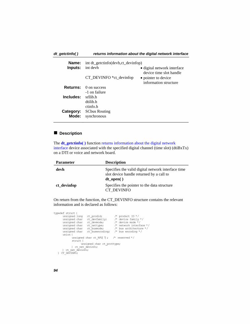
dt_getctinfo( ) returns information about the digital network interface
int dt_getctinfo(devh,ct_devinfop) Name: Inputs: int devh • digital network interface
device time slot handle CT_DEVINFO *ct_devinfop • pointer to device
information structure 0 on success -1 on failure
Returns:
srllib.h dtilib.h ctinfo.h
Includes:
SCbus Routing Category: synchronous Mode:
Description
The dt_getctinfo( ) function returns information about the digital network interface device associated with the specified digital channel (time slot) (dtiBxTx) on a DTI or voice and network board.
Parameter Description
devh Specifies the valid digital network interface time slot device handle returned by a call to dt_open( )
ct_devinfop Specifies the pointer to the data structure CT_DEVINFO
On return from the function, the CT_DEVINFO structure contains the relevant information and is declared as follows:
typedef struct { unsigned long ct_prodid; /* product ID */ unsigned char ct_devfamily; /* device family */ unsigned char ct_devmode; /* device mode */ unsigned char ct_nettype; /* network interface */ unsigned char ct_busmode; /* bus architecture */ unsigned char ct_busencoding; /* bus encoding */ union { unsigned char ct_RFU[7]; /* reserved */ struct { unsigned char ct_prottype; } ct_net_devinfo; } ct_ext_devinfo; } CT_DEVINFO;
94
returns information about the digital network interface dt_getctinfo( )
Valid values for each member of the CT_DEVINFO structure are defined in ctinfo.h. Possible return values are:
ct_prodid: field contains a valid product identification number for the device.
ct_devfamily: specifies the device family and contains: • CT_DFSPAN - specifies a T1 or E1 digital interface device
ct_devmode: not valid for T1 or E1 devices
ct_nettype: specifies the type of network interface for the device. The valid values are: • CT_NTT1 - specifies a T1 digital channel • CT_NTE1 - specifies an E1 digital channel
ct_busmode: specifies the bus architecture used to communicate with other devices in the system. The valid values are: • CT_BMSCBUS - specifies SCbus architecture • CT_BMH100 - specifies H.100 or CT Bus architecture
ct_ext_devinfo.ct_net_devinfo.ct_prottype: contains information about the protocol used on the specified digital network interface device. The following values are currently supported: • CT_ISDN • CT_CAS • CT_R2MF • CT_CLEAR
NOTE: The ct_ext_devinfo.ct_net_devinfo.ct_prottype field is not supported on Dialogic® Springware JCT Boards.
Cautions
This function will fail if an invalid time slot device handle is specified.
95
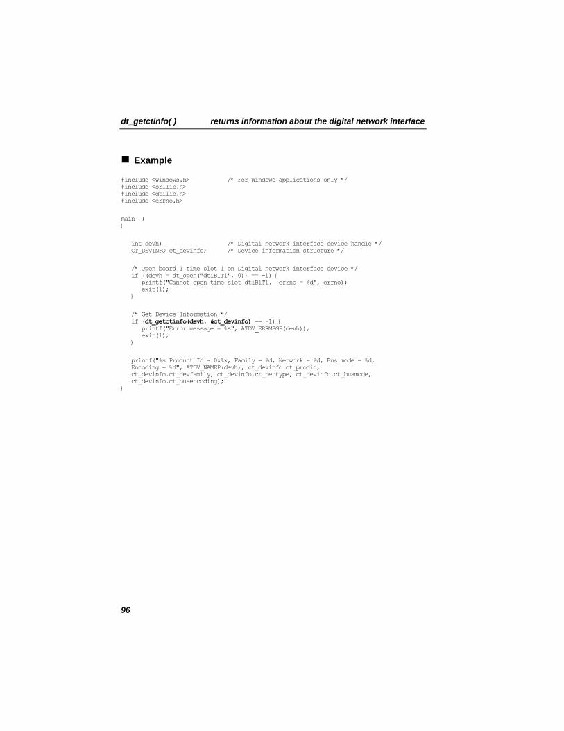
dt_getctinfo( ) returns information about the digital network interface
Example
#include <windows.h> /* For Windows applications only */ #include <srllib.h> #include <dtilib.h> #include <errno.h>
main( ) {
int devh; /* Digital network interface device handle */ CT_DEVINFO ct_devinfo; /* Device information structure */
/* Open board 1 time slot 1 on Digital network interface device */ if ((devh = dt_open("dtiB1T1", 0)) == -1) { printf("Cannot open time slot dtiB1T1. errno = %d", errno); exit(1); }
/* Get Device Information */ if (dt_getctinfo(devh, &ct_devinfo) == -1) { printf("Error message = %s", ATDV_ERRMSGP(devh)); exit(1); }
printf("%s Product Id = 0x%x, Family = %d, Network = %d, Bus mode = %d, Encoding = %d", ATDV_NAMEP(devh), ct_devinfo.ct_prodid, ct_devinfo.ct_devfamily, ct_devinfo.ct_nettype, ct_devinfo.ct_busmode, ct_devinfo.ct_busencoding); }
96
returns information about the digital network interface dt_getctinfo( )
Errors
If the function returns -1, use the SRL Standard Attribute function ATDV_LASTERR( ) to obtain the error code or use ATDV_ERRMSGP( ) to obtain a descriptive error message. The error codes returned by ATDV_LASTERR( ) are:
• EDT_BADBRDERR - board missing or defective • EDT_BADCMDERR - invalid command parameter to driver • EDT_FWERR - firmware returned an error • EDT_INVTS - invalid time slot device handle • EDT_INVMSG - invalid message • EDT_SH_BADLCLTS - invalid local time slot number • EDT_SH_BADINDX - invalid switch handler library index number • EDT_SH_BADTYPE - invalid local time slot type • EDT_SH_LIBBSY - switch handler library busy • EDT_SH_LIBNOTINIT - switch handler library is uninitialized • EDT_SH_MISSING - switch handler is not present • EDT_SH_NOCLK - switch handler clock fallback failed • EDT_SYSTEM - system error • EDT_TMOERR - timed out waiting for reply from firmware
See Also
In the Dialogic Voice API Library Reference® :
• ag_getctinfo( ) • dx_getctinfo( )
97
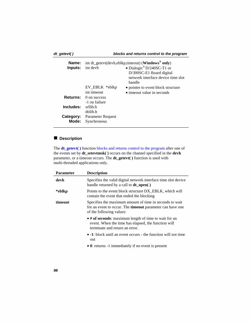
dt_getevt( ) blocks and returns control to the program
int dt_getevt(devh,eblkp,timeout) (Windows® only) Name: • Dialogic® D/240SC-T1 or
D/300SC-E1 Board digital network interface device time slot handle
Inputs: int devh
EV_EBLK *eblkp • pointer to event block structure int timeout • timeout value in seconds
0 on success Returns: -1 on failure srllib.h Includes: dtilib.h Parameter Request Category: Synchronous Mode:
Description
The dt_getevt( ) function blocks and returns control to the program after one of the events set by dt_setevtmsk( ) occurs on the channel specified in the devh parameter, or a timeout occurs. The dt_getevt( ) function is used with multi-threaded applications only.
Parameter Description
devh Specifies the valid digital network interface time slot device handle returned by a call to dt_open( )
*eblkp Points to the event block structure DX_EBLK, which will contain the event that ended the blocking
timeout Specifies the maximum amount of time in seconds to wait for an event to occur. The timeout parameter can have one of the following values: • # of seconds: maximum length of time to wait for an
event. When the time has elapsed, the function will terminate and return an error.
• -1: block until an event occurs - the function will not time out
• 0: returns -1 immediately if no event is present
98
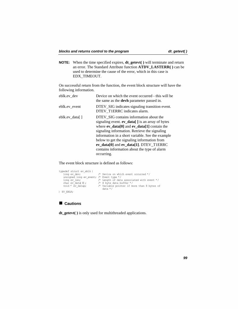
blocks and returns control to the program dt_getevt( )
NOTE: When the time specified expires, dt_getevt( ) will terminate and return an error. The Standard Attribute function ATDV_LASTERR( ) can be used to determine the cause of the error, which in this case is EDX_TIMEOUT.
On successful return from the function, the event block structure will have the following information. eblk.ev_dev Device on which the event occurred - this will be
the same as the devh parameter passed in. eblk.ev_event DTEV_SIG indicates signaling transition event.
DTEV_T1ERRC indicates alarm. eblk.ev_data[ ] DTEV_SIG contains information about the
signaling event. ev_data[ ] is an array of bytes where ev_data[0] and ev_data[1] contain the signaling information. Retrieve the signaling information in a short variable. See the example below to get the signaling information from ev_data[0] and ev_data[1]. DTEV_T1ERRC contains information about the type of alarm occurring.
The event block structure is defined as follows:
typedef struct ev_eblk { long ev_dev; /* Device on which event occurred */ unsigned long ev_event; /* Event type */ long ev_len; /* Length of data associated with event */ char ev_data[8]; /* 8 byte data buffer */ void * ev_datap; /* Variable pointer if more than 8 bytes of data */ } EV_EBLK;
Cautions
dt_getevt( ) is only used for multithreaded applications.
99
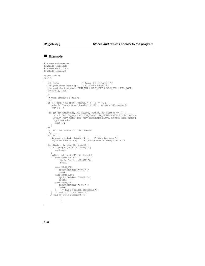
dt_getevt( ) blocks and returns control to the program
Example
#include <windows.h> #include <srllib.h> #include <dtilib.h> #include <errno.h>
EV_EBLK eblk; main() { int devh; /* Board device handle */ unsigned short bitmaskp; /* Bitmask variable */ unsigned short sigmsk = DTMM_AON | DTMM_AOFF | DTMM_BON | DTMM_BOFF; short sig, indx;
/* * Open Timeslot 1 device */ if ( ( devh = dt_open( "dtiB1T1", 0 ) ) == -1 ) { printf( "Cannot open timeslot dtiB1T1. errno = %d", errno ); exit( 1 ); } if (dt_setevtmsk(ddd, DTG_SIGEVT, sigmsk, DTA_SETMSK) == -1) { printf("%s: dt_setevtmsk DTG_SIGEVT DTA_SETMSK ERROR %d: %s: Mask = 0x%x\n",ATDV_NAMEP(ddd),ATDV_LASTERR(ddd),ATDV_ERRMSGP(ddd),sigmsk); dt_close(ddd); exit(1); } /* * Wait for events on this timeslot */ while(1) { dt_getevt ( devh, &eblk, -1 ); /* Wait for ever */ sig = eblk.ev_data[0] | ( (short) eblk.ev_data[1] << 8 );
for (indx = 0; indx <4; indx++) { if (!(sig & (0x1010 << indx))) { continue; } switch (sig & (0x1111 << indx)) { case DTMM_AOFF: fprintf(stderr,"A-OFF "); break;
case DTMM_AON: fprintf(stderr,"A-ON "); break; case DTMM_BOFF: fprintf(stderr,"B-OFF "); break; case DTMM_BON: fprintf(stderr,"B-ON "); break; } /* End of switch Statement */ } /* end of for statement */ } /* end of while statement */ . . . }
100
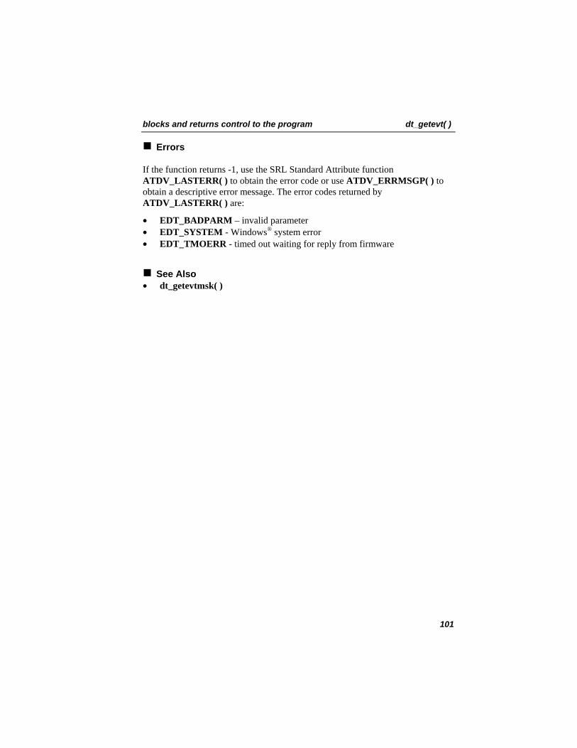
blocks and returns control to the program dt_getevt( )
Errors
If the function returns -1, use the SRL Standard Attribute function ATDV_LASTERR( ) to obtain the error code or use ATDV_ERRMSGP( ) to obtain a descriptive error message. The error codes returned by ATDV_LASTERR( ) are:
• EDT_BADPARM – invalid parameter • EDT_SYSTEM - Windows® system error • EDT_TMOERR - timed out waiting for reply from firmware
See Also • dt_getevtmsk( )
101
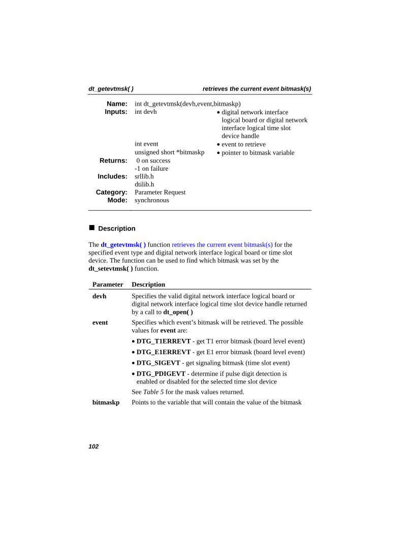
dt_getevtmsk( ) retrieves the current event bitmask(s)
int dt_getevtmsk(devh,event,bitmaskp) Name: Inputs: int devh • digital network interface
logical board or digital network interface logical time slot device handle
int event • event to retrieve unsigned short *bitmaskp • pointer to bitmask variable
0 on success -1 on failure
Returns:
srllib.h dtilib.h
Includes:
Parameter Request Category: synchronous Mode:
Description
The dt_getevtmsk( ) function retrieves the current event bitmask(s) for the specified event type and digital network interface logical board or time slot device. The function can be used to find which bitmask was set by the dt_setevtmsk( ) function.
Parameter Description
devh Specifies the valid digital network interface logical board or digital network interface logical time slot device handle returned by a call to dt_open( )
event Specifies which event’s bitmask will be retrieved. The possible values for event are:
• DTG_T1ERREVT - get T1 error bitmask (board level event) • DTG_E1ERREVT - get E1 error bitmask (board level event) • DTG_SIGEVT - get signaling bitmask (time slot event) • DTG_PDIGEVT - determine if pulse digit detection is
enabled or disabled for the selected time slot device See Table 5 for the mask values returned. bitmaskp Points to the variable that will contain the value of the bitmask
102
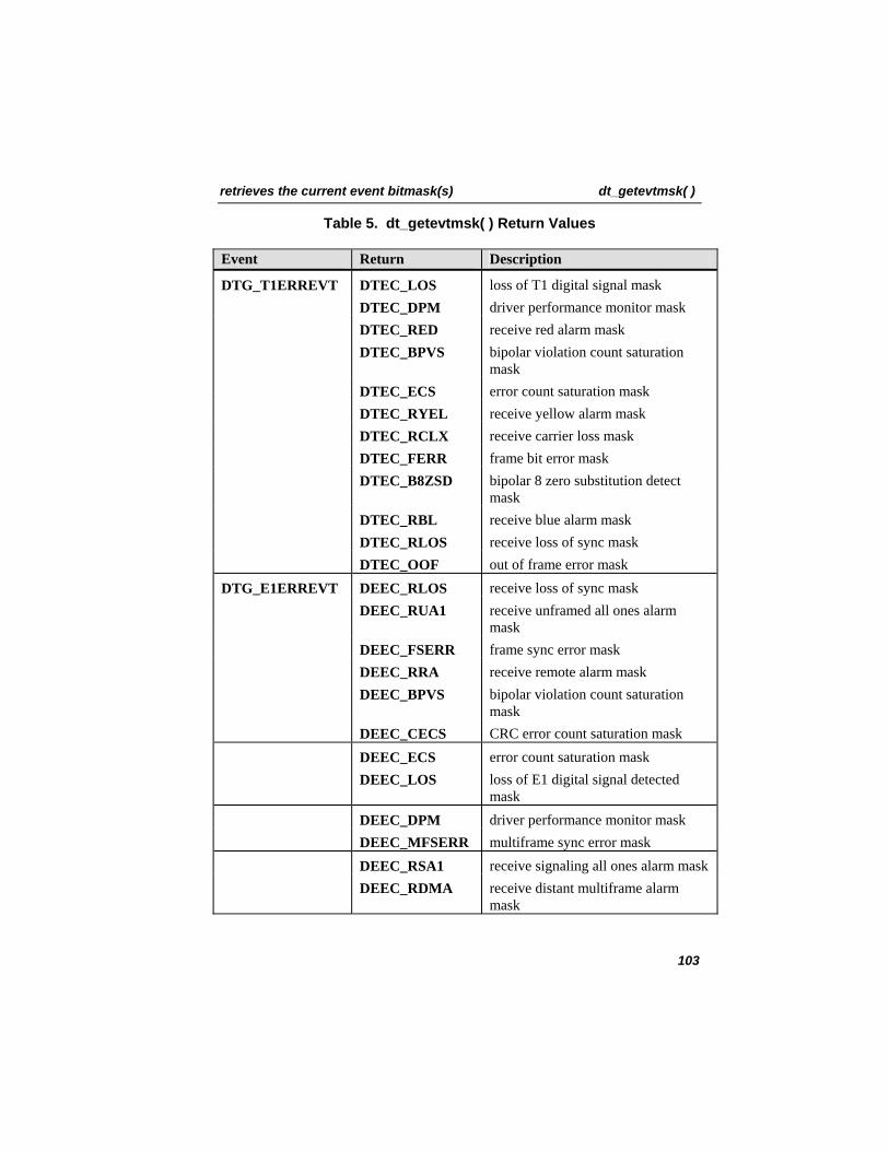
retrieves the current event bitmask(s) dt_getevtmsk( )
Table 5. dt_getevtmsk( ) Return Values
Event Return Description
DTG_T1ERREVT DTEC_LOS loss of T1 digital signal mask DTEC_DPM driver performance monitor mask DTEC_RED receive red alarm mask DTEC_BPVS bipolar violation count saturation
mask DTEC_ECS error count saturation mask DTEC_RYEL receive yellow alarm mask DTEC_RCLX receive carrier loss mask DTEC_FERR frame bit error mask DTEC_B8ZSD bipolar 8 zero substitution detect
mask DTEC_RBL receive blue alarm mask DTEC_RLOS receive loss of sync mask DTEC_OOF out of frame error mask DTG_E1ERREVT DEEC_RLOS receive loss of sync mask DEEC_RUA1 receive unframed all ones alarm
mask DEEC_FSERR frame sync error mask DEEC_RRA receive remote alarm mask DEEC_BPVS bipolar violation count saturation
mask DEEC_CECS CRC error count saturation mask DEEC_ECS error count saturation mask DEEC_LOS loss of E1 digital signal detected
mask DEEC_DPM driver performance monitor mask DEEC_MFSERR multiframe sync error mask DEEC_RSA1 receive signaling all ones alarm mask DEEC_RDMA receive distant multiframe alarm
mask
103
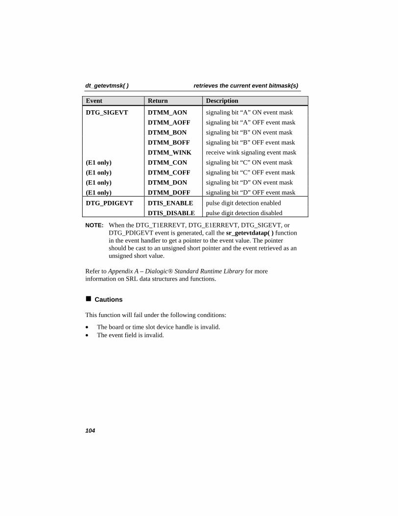
dt_getevtmsk( ) retrieves the current event bitmask(s)
Event Return Description
DTG_SIGEVT DTMM_AON signaling bit “A” ON event mask DTMM_AOFF signaling bit “A” OFF event mask DTMM_BON signaling bit “B” ON event mask DTMM_BOFF signaling bit “B” OFF event mask DTMM_WINK receive wink signaling event mask (E1 only) DTMM_CON signaling bit “C” ON event mask (E1 only) DTMM_COFF signaling bit “C” OFF event mask (E1 only) DTMM_DON signaling bit “D” ON event mask (E1 only) DTMM_DOFF signaling bit “D” OFF event mask DTG_PDIGEVT DTIS_ENABLE pulse digit detection enabled DTIS_DISABLE pulse digit detection disabled
NOTE: When the DTG_T1ERREVT, DTG_E1ERREVT, DTG_SIGEVT, or DTG_PDIGEVT event is generated, call the sr_getevtdatap( ) function in the event handler to get a pointer to the event value. The pointer should be cast to an unsigned short pointer and the event retrieved as an unsigned short value.
Refer to Appendix A – Dialogic® Standard Runtime Library for more information on SRL data structures and functions.
Cautions
This function will fail under the following conditions:
• The board or time slot device handle is invalid. • The event field is invalid.
104
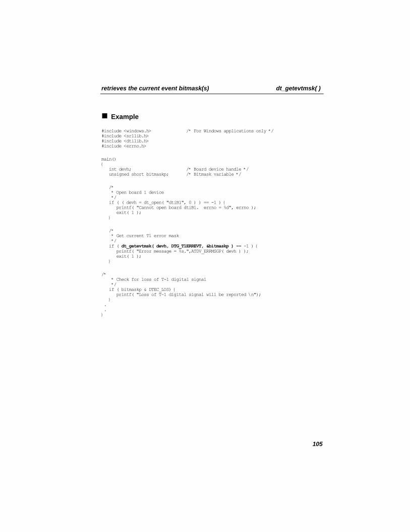
retrieves the current event bitmask(s) dt_getevtmsk( )
Example
#include <windows.h> /* For Windows applications only */ #include <srllib.h> #include <dtilib.h> #include <errno.h>
main() { int devh; /* Board device handle */ unsigned short bitmaskp; /* Bitmask variable */
/* * Open board 1 device */ if ( ( devh = dt_open( "dtiB1", 0 ) ) == -1 ) { printf( "Cannot open board dtiB1. errno = %d", errno ); exit( 1 ); }
/* * Get current T1 error mask */ if ( dt_getevtmsk( devh, DTG_T1ERREVT, &bitmaskp ) == -1 ) { printf( "Error message = %s.",ATDV_ERRMSGP( devh ) ); exit( 1 ); }
/* * Check for loss of T-1 digital signal */ if ( bitmaskp & DTEC_LOS) { printf( "Loss of T-1 digital signal will be reported \n"); } . . }
105

dt_getevtmsk( ) retrieves the current event bitmask(s)
Errors
If the function returns -1, use the SRL Standard Attribute function ATDV_LASTERR( ) to obtain the error code or use ATDV_ERRMSGP( ) to obtain a descriptive error message. See Appendix A – Dialogic® Standard Runtime Library for more information on SRL functions. The error codes returned by ATDV_LASTERR( ) are:
• EDT_BADBRDERR - digital network interface missing or defective • EDT_BADCMDERR - invalid or undefined command to driver • EDT_DATTO - data reception timed out • EDT_FWERR - firmware returned an error • EDT_INVBD - invalid digital network interface logical board device handle • EDT_INVTS - invalid digital network interface logical time slot device
handle • EDT_NOMEMERR - cannot map or allocate memory in driver • EDT_PARAMERR - invalid parameter • EDT_RANGEERR - bad/overlapping physical memory range • EDT_SIZERR - message too big or too small • EDT_SKIPRPLYERR - a required reply was skipped • EDT_SYSTEM - system error - check the global variable errno for more
information about the error • EDT_TMOERR - timed out waiting for reply from firmware
Error defines can be found in the file dtilib.h.
See Also
• dt_setevtmsk( ) • sr_enbhdlr( ) • sr_dishdlr( )
106
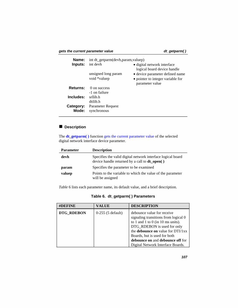
gets the current parameter value dt_getparm( )
int dt_getparm(devh,param,valuep) Name: Inputs: int devh • digital network interface
logical board device handle unsigned long param • device parameter defined name void *valuep • pointer to integer variable for
parameter value 0 on success -1 on failure
Returns:
srllib.h dtilib.h
Includes:
Parameter Request Category: synchronous Mode:
Description
The dt_getparm( ) function gets the current parameter value of the selected digital network interface device parameter.
Parameter Description
devh Specifies the valid digital network interface logical board device handle returned by a call to dt_open( )
param Specifies the parameter to be examined valuep Points to the variable to which the value of the parameter
will be assigned
Table 6 lists each parameter name, its default value, and a brief description.
Table 6. dt_getparm( ) Parameters
#DEFINE VALUE DESCRIPTION
DTG_RDEBON 0-255 (5 default) debounce value for receive signaling transitions from logical 0 to 1 and 1 to 0 (in 10 ms units). DTG_RDEBON is used for only the debounce on value for DTI/1xx Boards, but is used for both debounce on and debounce off for Digital Network Interface Boards.
107
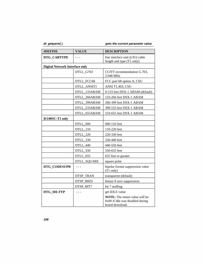
dt_getparm( ) gets the current parameter value
#DEFINE VALUE DESCRIPTION
DTG_CABTYPE - - - line interface unit (LIU) cable length and type (T1 only):
Digital Network Interface only DTLL_G703 CCITT recommendation G.703,
2.048 MHz DTLL_FCC68 FCC part 68 option A, CSU DTLL_ANSIT1 ANSI T1.403, CSU DTLL_133ABAM 0-133 feet DSX-1 ABAM (default) DTLL_266ABAM 133-266 feet DSX-1 ABAM DTLL_399ABAM 266-399 feet DSX-1 ABAM DTLL_533ABAM 399-533 feet DSX-1 ABAM DTLL_655ABAM 533-655 feet DSX-1 ABAM D/240SC-T1 only DTLL_000 000-110 feet DTLL_110 110-220 feet DTLL_220 220-330 feet DTLL_330 330-440 feet DTLL_440 440-550 feet DTLL_550 550-655 feet DTLL_655 655 feet or greater DTLL_SQUARE square pulse DTG_CODESUPR - - - bipolar format suppression value
(T1 only) DTSP_TRAN transparent (default) DTSP_B8ZS binary 8 zero suppression DTSP_BIT7 bit 7 stuffing DTG_IDLTYP - - - get IDLE value
NOTE: The return value will be 0x00 if idle was disabled during board download.
108
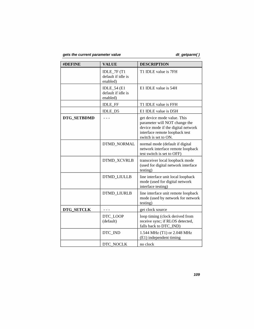
gets the current parameter value dt_getparm( )
#DEFINE VALUE DESCRIPTION
IDLE_7F (T1 default if idle is enabled)
T1 IDLE value is 7FH
IDLE_54 (E1 default if idle is enabled)
E1 IDLE value is 54H
IDLE_FF T1 IDLE value is FFH IDLE_D5 E1 IDLE value is D5H DTG_SETBDMD - - - get device mode value. This
parameter will NOT change the device mode if the digital network interface remote loopback test switch is set to ON.
DTMD_NORMAL normal mode (default if digital network interface remote loopback test switch is set to OFF)
DTMD_XCVRLB transceiver local loopback mode (used for digital network interface testing)
DTMD_LIULLB line interface unit local loopback mode (used for digital network interface testing)
DTMD_LIURLB line interface unit remote loopback mode (used by network for network testing)
DTG_SETCLK - - - get clock source DTC_LOOP
(default) loop timing (clock derived from receive sync; if RLOS detected, falls back to DTC_IND)
DTC_IND 1.544 MHz (T1) or 2.048 MHz (E1) independent timing
DTC_NOCLK no clock
109
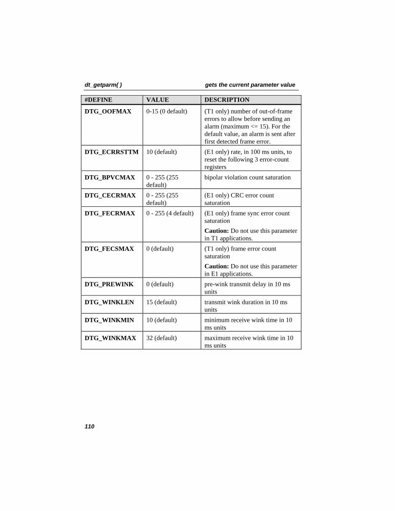
dt_getparm( ) gets the current parameter value
#DEFINE VALUE DESCRIPTION
DTG_OOFMAX 0-15 (0 default) (T1 only) number of out-of-frame errors to allow before sending an alarm (maximum <= 15). For the default value, an alarm is sent after first detected frame error.
DTG_ECRRSTTM 10 (default) (E1 only) rate, in 100 ms units, to reset the following 3 error-count registers
DTG_BPVCMAX 0 - 255 (255 default)
bipolar violation count saturation
DTG_CECRMAX 0 - 255 (255 default)
(E1 only) CRC error count saturation
DTG_FECRMAX 0 - 255 (4 default) (E1 only) frame sync error count saturation Caution: Do not use this parameter in T1 applications.
DTG_FECSMAX 0 (default) (T1 only) frame error count saturation Caution: Do not use this parameter in E1 applications.
DTG_PREWINK 0 (default) pre-wink transmit delay in 10 ms units
DTG_WINKLEN 15 (default) transmit wink duration in 10 ms units
DTG_WINKMIN 10 (default) minimum receive wink time in 10 ms units
DTG_WINKMAX 32 (default) maximum receive wink time in 10 ms units
110
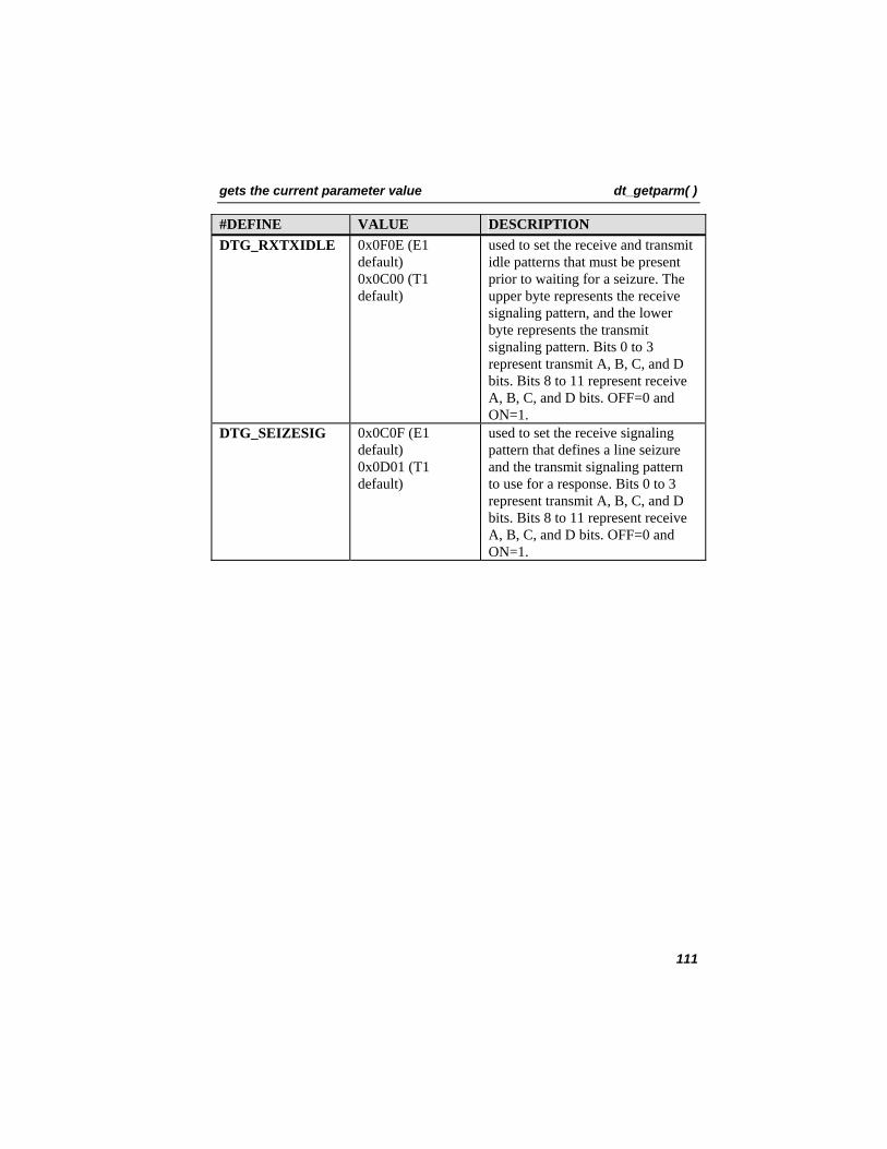
gets the current parameter value dt_getparm( )
#DEFINE VALUE DESCRIPTION DTG_RXTXIDLE 0x0F0E (E1
default) 0x0C00 (T1 default)
used to set the receive and transmit idle patterns that must be present prior to waiting for a seizure. The upper byte represents the receive signaling pattern, and the lower byte represents the transmit signaling pattern. Bits 0 to 3 represent transmit A, B, C, and D bits. Bits 8 to 11 represent receive A, B, C, and D bits. OFF=0 and ON=1.
DTG_SEIZESIG 0x0C0F (E1 default) 0x0D01 (T1 default)
used to set the receive signaling pattern that defines a line seizure and the transmit signaling pattern to use for a response. Bits 0 to 3 represent transmit A, B, C, and D bits. Bits 8 to 11 represent receive A, B, C, and D bits. OFF=0 and ON=1.
111
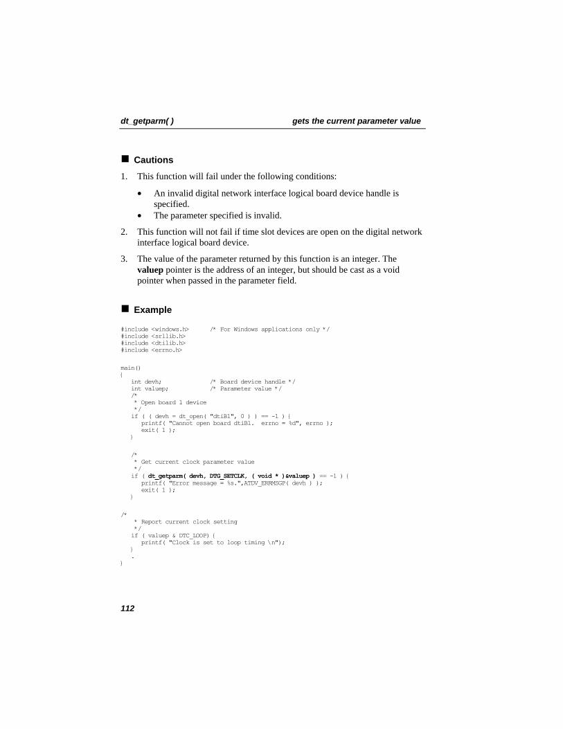
dt_getparm( ) gets the current parameter value
Cautions
1. This function will fail under the following conditions:
• An invalid digital network interface logical board device handle is specified.
• The parameter specified is invalid.
2. This function will not fail if time slot devices are open on the digital network interface logical board device.
3. The value of the parameter returned by this function is an integer. The valuep pointer is the address of an integer, but should be cast as a void pointer when passed in the parameter field.
Example
#include <windows.h> /* For Windows applications only */ #include <srllib.h> #include <dtilib.h> #include <errno.h>
main() { int devh; /* Board device handle */ int valuep; /* Parameter value */ /* * Open board 1 device */ if ( ( devh = dt_open( "dtiB1", 0 ) ) == -1 ) { printf( "Cannot open board dtiB1. errno = %d", errno ); exit( 1 ); }
/* * Get current clock parameter value */ if ( dt_getparm( devh, DTG_SETCLK, ( void * )&valuep ) == -1 ) { printf( "Error message = %s.",ATDV_ERRMSGP( devh ) ); exit( 1 ); }
/* * Report current clock setting */ if ( valuep & DTC_LOOP) { printf( "Clock is set to loop timing \n"); } . }
112
gets the current parameter value dt_getparm( )
Errors
If the function returns -1, use the SRL Standard Attribute function ATDV_LASTERR( ) to obtain the error code or use ATDV_ERRMSGP( ) to obtain a descriptive error message. See Appendix A – Dialogic® Standard Runtime Library for more information on SRL functions. The error codes returned by ATDV_LASTERR( ) are:
• EDT_BADBRDERR - digital network interface missing or defective • EDT_BADCMDERR - invalid or undefined command to driver • EDT_BADGLOB - invalid param value • EDT_FWERR - firmware returned an error • EDT_INVBD - invalid digital network interface logical board device handle • EDT_NOMEMERR - cannot map or allocate memory in driver • EDT_PARAMERR - invalid parameter • EDT_RANGEERR - bad/overlapping physical memory range • EDT_SIZERR - message too big or too small • EDT_SKIPRPLYERR - a required reply was skipped • EDT_SYSTEM - system error - check the global variable errno for more
information about the error • EDT_TMOERR - timed out waiting for reply from firmware
Error defines can be found in the file dtilib.h.
See Also
• dt_setparm( )
113
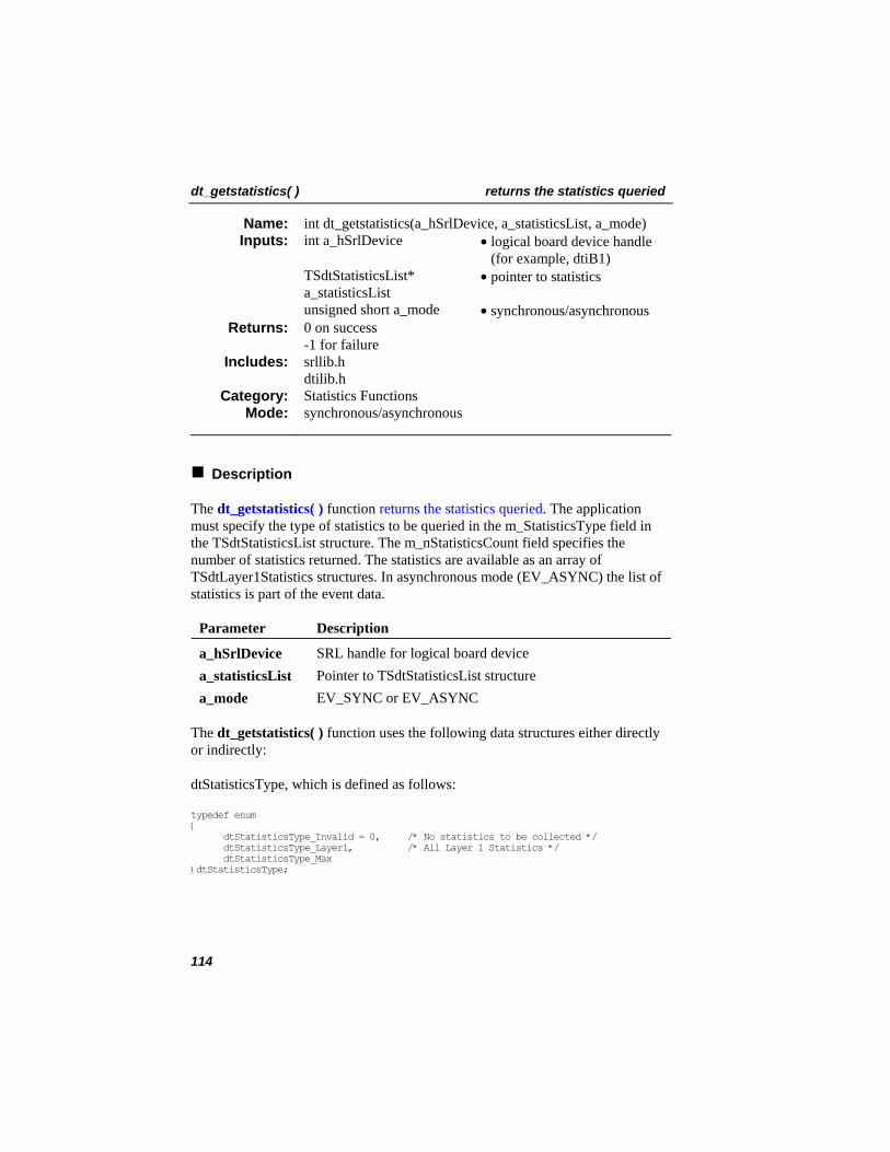
dt_getstatistics( ) returns the statistics queried
int dt_getstatistics(a_hSrlDevice, a_statisticsList, a_mode) Name: Inputs: int a_hSrlDevice • logical board device handle
(for example, dtiB1) TSdtStatisticsList*
a_statisticsList • pointer to statistics
unsigned short a_mode • synchronous/asynchronous 0 on success -1 for failure
Returns:
srllib.h dtilib.h
Includes:
Statistics Functions Category: synchronous/asynchronous Mode:
Description
The dt_getstatistics( ) function returns the statistics queried. The application must specify the type of statistics to be queried in the m_StatisticsType field in the TSdtStatisticsList structure. The m_nStatisticsCount field specifies the number of statistics returned. The statistics are available as an array of TSdtLayer1Statistics structures. In asynchronous mode (EV_ASYNC) the list of statistics is part of the event data.
Parameter Description
a_hSrlDevice SRL handle for logical board device a_statisticsList Pointer to TSdtStatisticsList structure a_mode EV_SYNC or EV_ASYNC
The dt_getstatistics( ) function uses the following data structures either directly or indirectly:
dtStatisticsType, which is defined as follows:
typedef enum { dtStatisticsType_Invalid = 0, /* No statistics to be collected */ dtStatisticsType_Layer1, /* All Layer 1 Statistics */ dtStatisticsType_Max }dtStatisticsType;
114
returns the statistics queried dt_getstatistics( )
dtStatisticsMode, which is defined as follows:
typedef enum { dtStatisticsMode_Invalid = 0, /* No statistics Mode */ dtStatisticsMode_Clear, /* Clear statistics counters */ dtStatisticsMode_Preserve, /* Preserve statistics counters */ dtStatisticsMode_Max }dtStatisticsMode;
dtLayer1StatisticsId, which is defined as follows:
typedef enum { dtLayer1StatisticsId_Invalid = 0, dtLayer1StatisticsId_LCV = 1, /* Line Coding Violations (LCV) */ dtLayer1StatisticsId_PCV, /* Path Coding Violations (PCV) */ dtLayer1StatisticsId_ES, /* Errored Seconds (ES) */ dtLayer1StatisticsId_SES, /* Severely Errored Seconds (SES) */ dtLayer1StatisticsId_UAS, /* Unavailable Seconds (UAS) */ dtLayer1StatisticsId_BES, /* Bursty Errored Seconds (BES) */ dtLayer1StatisticsId_LOFC, /* Loss of Frame Count (LOFC) */ dtLayer1StatisticsId_CSS, /* Controlled Slip Seconds (CSS) */ dtLayer1StatisticsId_SEFS, /* Severly Errored Framing Seconds (SEFS) */ dtLayer1StatisticsId_LES, /* Line Errored Seconds (LES) */ dtLayer1StatisticsId_MAX }dtLayer1StatisticsId;
TSdtLayer1Statistics, which is defined as follows:
typedef struc SdtLayer1Statistics { dtLayer1StatisticsId m_Layer1StatisticsId; unsigned int m_nIntervalTotal; unsigned int m_nCurrentIntervalTimer; unsigned int m_nCurrentValue; unsigned int m_nPreviousValue; }TSdtLayer1Statistics;
TSdtStatisticsList, which is defined as follows:
typedef struc SdtStatisticsList { unsigned int m_nVersion; /* Version of this structure */ dtStatisticsType m_StatisticsType; /* Statistics Type */ dtStatisticsMode m_StatisticsMode; /* Statistics Mode */ unsigned int m_nStatisticsCount; /* Statistics Count */ union { TSdtLayer1Statistics m_Layer1Statistics[dtLayer1StatisticsId_Max]; }m_Stats; }TSdtLayer1Statistics;
115
dt_getstatistics( ) returns the statistics queried
Cautions
None.
Example
/* OS Header Files */ #ifdef WIN32 #include <windows.h> #include <process.h> /* _beginthread, _endthread */ #include <conio.h> #else #include <unistd.h> #endif #include <stdio.h> #include <iostream.h> #include <iomanip.h> #include <errno.h> #include <stddef.h> #include <stdlib.h> #include <string.h> #include <signal.h> #include <sys/timeb.h> #include <time.h>
/* Dialogic Header Files */ #include <gcip.h> #include <gclib.h> #include <gcisdn.h> #include <dtilib.h> #include <srllib.h>
bool repeat = true; /*Global repeat flag and video variable */ bool EventReceived = true; LINEDEV a_LineDev=0; LINEDEV a_BoardDev=0; void sig_hdlr(int temp); void OpenBoard(void);
long EventHandler (unsigned long temp) { unsigned int Loop=0; int dev=sr_getevtdev(); long event=sr_getevttype(); TSdtStatisticsList* myStatisticsList=(TSdtStatisticsList*) sr_getevtdatap();; printf(“DevH = %d Event = 0x%X\n”,dev,event); if(event==DTEV_GETSTATISTICS) { printf(“TSdtStatisticsList – Version(%d) StatisticsType(0x%X) Count(%d) Mode(%d)\n”, myStatisticsList->m_nVersion,myStatisticsList->m_StatisticsType, myStatisticsList->m_nStatisticsCount,myStatisticsList->m_StatisticsMode; for(Loop=0;Loop<myStatisticsList->m_nStatisticsCount;Loop++) { printf(“TSLayer1Statistics(%d) – Version(%d) StatisticsId(%d) Interval Total(%d) CurrentIntervalTimer(%d) CurrentValue(%d) PreviousValue(%d)\n”, Loop,
116
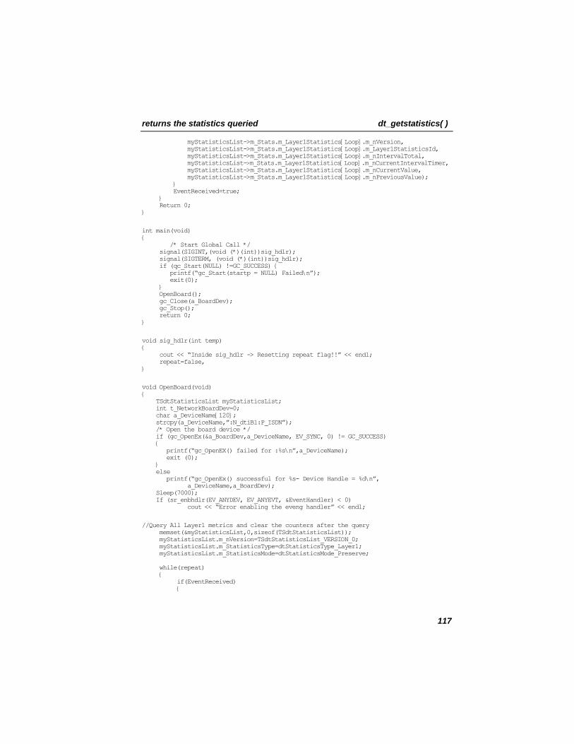
returns the statistics queried dt_getstatistics( )
myStatisticsList->m_Stats.m_Layer1Statistics[Loop].m_nVersion, myStatisticsList->m_Stats.m_Layer1Statistics[Loop].m_Layer1StatisticsId, myStatisticsList->m_Stats.m_Layer1Statistics[Loop].m_nIntervalTotal, myStatisticsList->m_Stats.m_Layer1Statistics[Loop].m_nCurrentIntervalTimer, myStatisticsList->m_Stats.m_Layer1Statistics[Loop].m_nCurrentValue, myStatisticsList->m_Stats.m_Layer1Statistics[Loop].m_nPreviousValue); } EventReceived=true; } Return 0; }
int main(void) { /* Start Global Call */ signal(SIGINT,(void (*)(int))sig_hdlr); signal(SIGTERM, (void (*)(int))sig_hdlr); if (qc_Start(NULL) !=GC_SUCCESS) { printf(“gc_Start(startp = NULL) Failed\n”); exit(0); } OpenBoard(); gc_Close(a_BoardDev); gc_Stop(); return 0; }
void sig_hdlr(int temp) { cout << “Inside sig_hdlr -> Resetting repeat flag!!” << endl; repeat=false, }
void OpenBoard(void) { TSdtStatisticsList myStatisticsList; int t_NetworkBoardDev=0; char a_DeviceName[120]; strcpy(a_DeviceName,”:N_dtiB1:P_ISDN”); /* Open the board device */ if (gc_OpenEx(&a_BoardDev,a_DeviceName, EV_SYNC, 0) != GC_SUCCESS) { printf(“gc_OpenEX() failed for :%s\n”,a_DeviceName); exit (0); } else printf(“gc_OpenEx() successful for %s- Device Handle = %d\n”, a_DeviceName,a_BoardDev); Sleep(7000); If (sr_enbhdlr(EV_ANYDEV, EV_ANYEVT, &EventHandler) < 0) cout << “Error enabling the eveng handler” << endl;
//Query All Layer1 metrics and clear the counters after the query memset(&myStatisticsList,0,sizeof(TSdtStatisticsList)); myStatisticsList.m_nVersion=TSdtStatisticsList_VERSION_0; myStatisticsList.m_StatisticsType=dtStatisticsType_Layer1; myStatisticsList.m_StatisticsMode=dtStatisticsMode_Preserve; while(repeat) { if(EventReceived) {
117
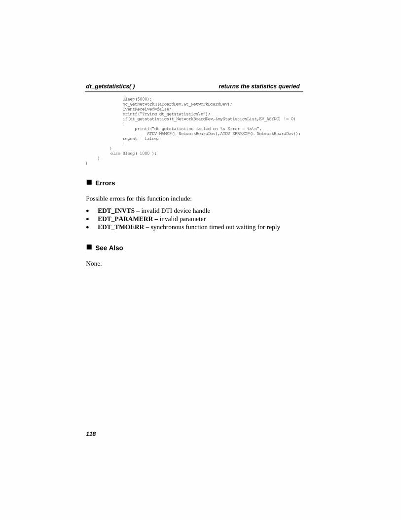
dt_getstatistics( ) returns the statistics queried
Sleep(5000); qc_GetNetworkH(aBoardDev,&t_NetworkBoardDev); EventReceived=false; printf(“Trying dt_getstatistics\n”); if(dt_getstatistics(t_NetworkBoardDev,&myStatisticsList,EV_ASYNC) != 0) { printf(“dt_getstatistics failed on %s Error = %s\n”, ATDV_NAMEP(t_NetworkBoardDev),ATDV_ERRMSGP(t_NetworkBoardDev)); repeat = false; } } else Sleep( 1000 ); } }
Errors
Possible errors for this function include:
• EDT_INVTS – invalid DTI device handle • EDT_PARAMERR – invalid parameter • EDT_TMOERR – synchronous function timed out waiting for reply
See Also
None.
118
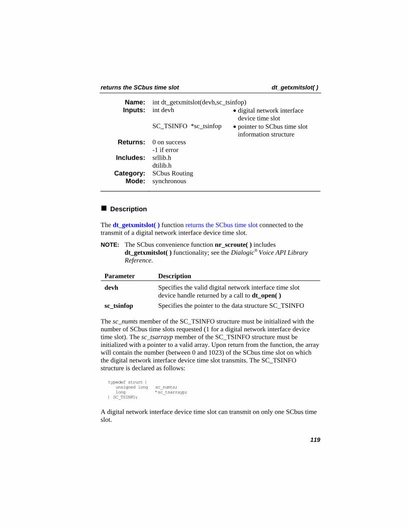
returns the SCbus time slot dt_getxmitslot( )
int dt_getxmitslot(devh,sc_tsinfop) Name: Inputs: int devh • digital network interface
device time slot SC_TSINFO *sc_tsinfop • pointer to SCbus time slot
information structure 0 on success -1 if error
Returns:
srllib.h dtilib.h
Includes:
SCbus Routing Category: synchronous Mode:
Description
The dt_getxmitslot( ) function returns the SCbus time slot connected to the transmit of a digital network interface device time slot.
NOTE: The SCbus convenience function nr_scroute( ) includes dt_getxmitslot( ) functionality; see the Dialogic® Voice API Library Reference.
Parameter Description
devh Specifies the valid digital network interface time slot device handle returned by a call to dt_open( )
sc_tsinfop Specifies the pointer to the data structure SC_TSINFO
The sc_numts member of the SC_TSINFO structure must be initialized with the number of SCbus time slots requested (1 for a digital network interface device time slot). The sc_tsarrayp member of the SC_TSINFO structure must be initialized with a pointer to a valid array. Upon return from the function, the array will contain the number (between 0 and 1023) of the SCbus time slot on which the digital network interface device time slot transmits. The SC_TSINFO structure is declared as follows:
typedef struct { unsigned long sc_numts; long *sc_tsarrayp; } SC_TSINFO;
A digital network interface device time slot can transmit on only one SCbus time slot.
119
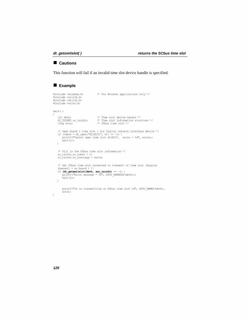
dt_getxmitslot( ) returns the SCbus time slot
Cautions
This function will fail if an invalid time slot device handle is specified.
Example
#include <windows.h> /* For Windows applications only */ #include <srllib.h> #include <dtilib.h> #include <errno.h>
main( ) { int devh; /* Time slot device handle */ SC_TSINFO sc_tsinfo; /* Time slot information structure */ long scts; /* SCbus time slot */
/* Open board 1 time slot 1 for Digital network interface device */ if ((devh = dt_open("dtiB1T1", 0)) == -1) { printf("Cannot open time slot dtiB1T1. errno = %d", errno); exit(1); }
/* Fill in the SCbus time slot information */ sc_tsinfo.sc_numts = 1; sc_tsinfo.sc_tsarrayp = &scts;
/* Get SCbus time slot connected to transmit of time slot (digital channel) 1 on board 1 */ if (dt_getxmitslot(devh, &sc_tsinfo) == -1) { printf("Error message = %s", ATDV_ERRMSGP(devh)); exit(1); }
printf("%s is transmitting on SCbus time slot %d", ATDV_NAMEP(devh), scts); }
120
returns the SCbus time slot dt_getxmitslot( )
Errors
If the function returns -1, use the SRL Standard Attribute function ATDV_LASTERR( ) to obtain the error code or use ATDV_ERRMSGP( ) to obtain a descriptive error message. The error codes returned by ATDV_LASTERR( ) are:
• EDT_BADBRDERR - board missing or defective • EDT_BADCMDERR - invalid command parameter to driver • EDT_FWERR - firmware returned an error • EDT_INVTS - invalid time slot device handle • EDT_INVMSG - invalid message • EDT_SH_BADLCLTS - invalid local time slot number • EDT_SH_BADINDX - invalid switch handler library index number • EDT_SH_BADMODE - invalid switch handler bus configuration • EDT_SH_BADTYPE - invalid local time slot type • EDT_SH_LCLDSCNCT - local time slot is already disconnected from the
SCbus • EDT_SH_LIBBSY - switch handler library busy • EDT_SH_LIBNOTINIT - switch handler library is uninitialized • EDT_SH_MISSING - switch handler is not present • EDT_SH_NOCLK - switch handler clock fallback failed • EDT_SYSTEM - system error • EDT_TMOERR - timed out waiting for reply from firmware
See Also
In the Dialogic Voice API Library Reference® :
• ag_listen( ) • dx_listen( )
121
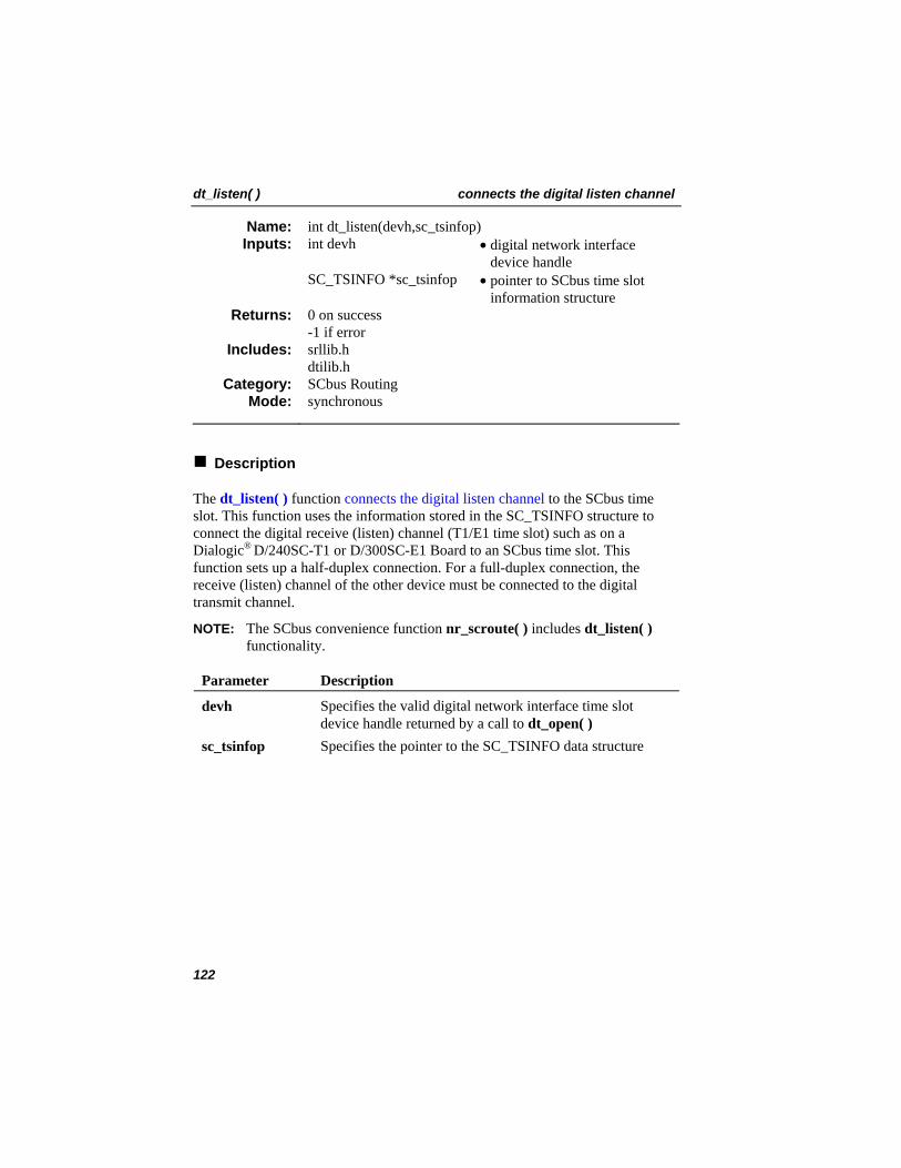
dt_listen( ) connects the digital listen channel
int dt_listen(devh,sc_tsinfop) Name: Inputs: int devh • digital network interface
device handle SC_TSINFO *sc_tsinfop • pointer to SCbus time slot
information structure 0 on success -1 if error
Returns:
srllib.h dtilib.h
Includes:
SCbus Routing Category: synchronous Mode:
Description
The dt_listen( ) function connects the digital listen channel to the SCbus time slot. This function uses the information stored in the SC_TSINFO structure to connect the digital receive (listen) channel (T1/E1 time slot) such as on a Dialogic® D/240SC-T1 or D/300SC-E1 Board to an SCbus time slot. This function sets up a half-duplex connection. For a full-duplex connection, the receive (listen) channel of the other device must be connected to the digital transmit channel.
NOTE: The SCbus convenience function nr_scroute( ) includes dt_listen( ) functionality.
Parameter Description
devh Specifies the valid digital network interface time slot device handle returned by a call to dt_open( )
sc_tsinfop Specifies the pointer to the SC_TSINFO data structure
122
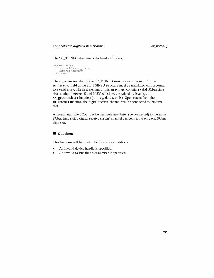
connects the digital listen channel dt_listen( )
The SC_TSINFO structure is declared as follows:
typedef struct { unsigned long sc_numts; long *sc_tsarrayp; } SC_TSINFO;
The sc_numts member of the SC_TSINFO structure must be set to 1. The sc_tsarrayp field of the SC_TSINFO structure must be initialized with a pointer to a valid array. The first element of this array must contain a valid SCbus time slot number (between 0 and 1023) which was obtained by issuing an xx_getxmitslot( ) function (xx = ag, dt, dx, or fx). Upon return from the dt_listen( ) function, the digital receive channel will be connected to this time slot.
Although multiple SCbus device channels may listen (be connected) to the same SCbus time slot, a digital receive (listen) channel can connect to only one SCbus time slot.
Cautions
This function will fail under the following conditions:
• An invalid device handle is specified. • An invalid SCbus time slot number is specified.
123
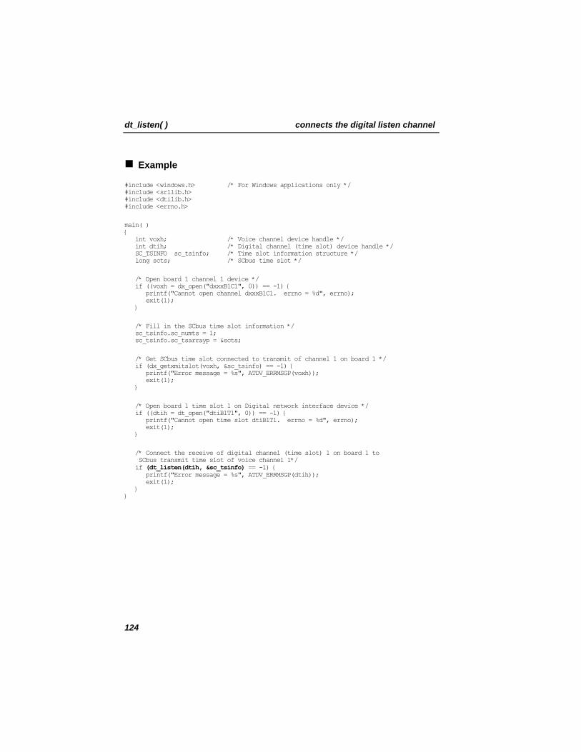
dt_listen( ) connects the digital listen channel
Example
#include <windows.h> /* For Windows applications only */ #include <srllib.h> #include <dtilib.h> #include <errno.h>
main( ) { int voxh; /* Voice channel device handle */ int dtih; /* Digital channel (time slot) device handle */ SC_TSINFO sc_tsinfo; /* Time slot information structure */ long scts; /* SCbus time slot */
/* Open board 1 channel 1 device */ if ((voxh = dx_open("dxxxB1C1", 0)) == -1) { printf("Cannot open channel dxxxB1C1. errno = %d", errno); exit(1); }
/* Fill in the SCbus time slot information */ sc_tsinfo.sc_numts = 1; sc_tsinfo.sc_tsarrayp = &scts;
/* Get SCbus time slot connected to transmit of channel 1 on board 1 */ if (dx_getxmitslot(voxh, &sc_tsinfo) == -1) { printf("Error message = %s", ATDV_ERRMSGP(voxh)); exit(1); }
/* Open board 1 time slot 1 on Digital network interface device */ if ((dtih = dt_open("dtiB1T1", 0)) == -1) { printf("Cannot open time slot dtiB1T1. errno = %d", errno); exit(1); }
/* Connect the receive of digital channel (time slot) 1 on board 1 to SCbus transmit time slot of voice channel 1*/ if (dt_listen(dtih, &sc_tsinfo) == -1) { printf("Error message = %s", ATDV_ERRMSGP(dtih)); exit(1); } }
124
connects the digital listen channel dt_listen( )
Errors
If the function returns -1, use the SRL Standard Attribute function ATDV_LASTERR( ) to obtain the error code or use ATDV_ERRMSGP( ) to obtain a descriptive error message. The error codes returned by ATDV_LASTERR( ) are:
• EDT_BADBRDERR - board missing or defective • EDT_BADCMDERR - invalid command parameter to driver • EDT_FWERR - firmware returned an error • EDT_INVTS - invalid time slot device handle • EDT_INVMSG - invalid message • EDT_SH_BADLCLTS - invalid local time slot number • EDT_SH_BADEXTTS - external time slot unsupported at current clock rate • EDT_SH_BADINDX - invalid switch handler library index number • EDT_SH_BADMODE - invalid switch handler bus configuration • EDT_SH_BADTYPE - invalid local time slot type • EDT_SH_LCLTSCNCT - local time slot is already connected to SCbus • EDT_SH_LIBBSY - switch handler library busy • EDT_SH_LIBNOTINIT - switch handler library is uninitialized • EDT_SH_MISSING - switch handler is not present • EDT_SH_NOCLK - switch handler clock fallback failed • EDT_SYSTEM - system error • EDT_TMOERR - timed out waiting for reply from firmware
See Also
• dt_unlisten( )
125
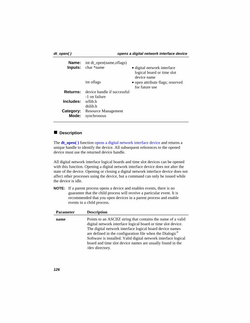
dt_open( ) opens a digital network interface device
int dt_open(name,oflags) Name: Inputs: char *name • digital network interface
logical board or time slot device name
int oflags • open attribute flags; reserved for future use
device handle if successful -1 on failure
Returns:
srllib.h dtilib.h
Includes:
Resource Management Category: synchronous Mode:
Description
The dt_open( ) function opens a digital network interface device and returns a unique handle to identify the device. All subsequent references to the opened device must use the returned device handle.
All digital network interface logical boards and time slot devices can be opened with this function. Opening a digital network interface device does not alter the state of the device. Opening or closing a digital network interface device does not affect other processes using the device, but a command can only be issued while the device is idle.
NOTE: If a parent process opens a device and enables events, there is no guarantee that the child process will receive a particular event. It is recommended that you open devices in a parent process and enable events in a child process.
Parameter Description
name Points to an ASCIIZ string that contains the name of a valid digital network interface logical board or time slot device. The digital network interface logical board device names are defined in the configuration file when the Dialogic®
Software is installed. Valid digital network interface logical board and time slot device names are usually found in the /dev directory.
126
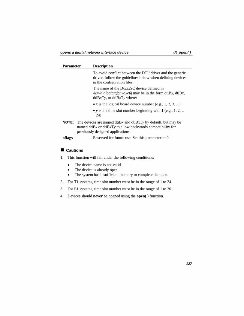
opens a digital network interface device dt_open( )
Parameter Description
To avoid conflict between the DTI/ driver and the generic driver, follow the guidelines below when defining devices in the configuration files:
The name of the D/xxxSC device defined in /usr/dialogic/cfg/.voxcfg may be in the form dtiBx, dtiBx, dtiBxTTy, or dtiBxTyT where:
• x is the logical board device number (e.g., 1, 2, 3, ...) • y is the time slot number beginning with 1 (e.g., 1, 2, ..
24)
NOTE: The devices are named dtiBx and dtiBxTTy by default, but may be named dtiBx or dtiBxTyT to allow backwards compatibility for previously designed applications.
oflags Reserved for future use. Set this parameter to 0.
Cautions
1. This function will fail under the following conditions:
• The device name is not valid. • The device is already open. • The system has insufficient memory to complete the open.
2. For T1 systems, time slot number must be in the range of 1 to 24.
3. For E1 systems, time slot number must be in the range of 1 to 30.
4. Devices should never be opened using the open( ) function.
127
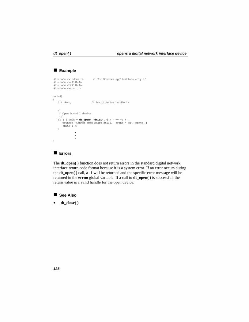
dt_open( ) opens a digital network interface device
Example
#include <windows.h> /* For Windows applications only */ #include <srllib.h> #include <dtilib.h> #include <errno.h>
main() { int devh; /* Board device handle */
/* * Open board 1 device */ if ( ( devh = dt_open( "dtiB1", 0 ) ) == -1 ) { printf( "Cannot open board dtiB1. errno = %d", errno ); exit( 1 ); } . . . }
Errors
The dt_open( ) function does not return errors in the standard digital network interface return code format because it is a system error. If an error occurs during the dt_open( ) call, a -1 will be returned and the specific error message will be returned in the errno global variable. If a call to dt_open( ) is successful, the return value is a valid handle for the open device.
See Also
• dt_close( )
128
runs diagnostics dt_rundiag( )
int dt_rundiag(devh,tmo,diagbufp) Name: Inputs: int devh • digital network interface
logical board device handle int tmo • timeout value char *diagbufp • pointer to 1-byte buffer for
diagnostic code 0 on success -1 on failure
Returns:
srllib.h dtilib.h
Includes:
Diagnostic Category: synchronous/asynchronous Mode:
Description
The dt_rundiag( ) function runs diagnostics on the network firmware. The function can operate in synchronous (blocking) or asynchronous (non-blocking) mode.
Note the following guidelines when using this function:
• This function can be issued at any time, but it is recommended that all time slots be idle and closed.
• This function is destructive to calls in progress. • The board will be restored to its previous state, that is, the state the board
was in before the function was called. • The function should take about 5 seconds to complete.
Parameter Description
devh Specifies the valid digital network interface board device handle returned by a call to dt_open( )
tmo When operating the function in synchronous mode, specifies the length of time in seconds the function will block while waiting for a response from the device
diagbufp Pointer to a one-byte data buffer to which the diagnostic code will be returned when the function is operating in synchronous mode
129
dt_rundiag( ) runs diagnostics
Synchronous Mode
To operate the function in synchronous (blocking) mode, specify in tmo the length of time in seconds that the function will block. This causes the application to wait for a return from the function before performing any other processing. A suggested setting for tmo is 5.
Asynchronous Mode
To operate the function in asynchronous (non-blocking) mode, set tmo to 0. This allows the application to continue processing while waiting for a completion event from the device.
If event handling is set up properly for your application, DTEV_RETDIAG is returned by the SRL sr_getevttype( ) function when the diagnostics are successfully completed.
To use this function in asynchronous mode, you must use the SRL sr_enbhdlr( ) function to enable trapping of the event and create an event handler to process the completion event returned by the device. See Appendix A – Dialogic® Standard Runtime Library for more information on digital network interface event management.
NOTE: To run this function in asynchronous operation, you must pass a NULL pointer to diagbufp.
Diagnostic Return Codes
The diagnostic codes listed below provide results of the diagnostics run on the digital network interface firmware. In synchronous mode, the diagnostic codes are returned to the one-byte buffer pointed to by diagbufp. In asynchronous mode, the codes are returned by the SRL sr_getevtdatap( ) function.
• D2DE_BRDCFG - invalid board configuration data • D2DE_INVEE - invalid EEPROM data (not valid for Dialogic® D/240SC-
T1 Board) • D2DE_LIUFAIL - read/write to LIU failed • D2DE_MEMTST - memory test failed • D2DE_NOERR - no errors • D2DE_ROMCHK - bad ROM checksum (not valid for Dialogic® D/240SC-
T1 Board)
130
runs diagnostics dt_rundiag( )
• D2DE_XCVRFAIL - read XCVR register failed
Cautions
1. This function will fail under the following conditions:
• An invalid digital network interface logical board device handle is specified.
• There is a firmware/hardware problem on the device.
2. Make sure all time slots are closed and idle. This function is destructive to calls in progress.
131
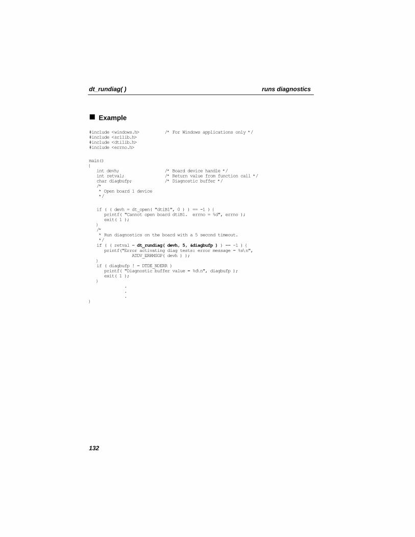
dt_rundiag( ) runs diagnostics
Example
#include <windows.h> /* For Windows applications only */ #include <srllib.h> #include <dtilib.h> #include <errno.h>
main() { int devh; /* Board device handle */ int retval; /* Return value from function call */ char diagbufp; /* Diagnostic buffer */ /* * Open board 1 device */
if ( ( devh = dt_open( "dtiB1", 0 ) ) == -1 ) { printf( "Cannot open board dtiB1. errno = %d", errno ); }
exit( 1 );
/* * Run diagnostics on the board with a 5 second timeout. */ if ( ( retval = dt_rundiag( devh, 5, &diagbufp ) ) == -1 ) { printf("Error activating diag tests: error message = %s\n", ATDV_ERRMSGP( devh ) ); } if ( diagbufp ! = DTDE_NOERR ) printf( "Diagnostic buffer value = %d\n", diagbufp ); exit( 1 ); } . . . }
132
runs diagnostics dt_rundiag( )
Errors
If the function returns -1, use the SRL Standard Attribute function ATDV_LASTERR( ) to obtain the error code or use ATDV_ERRMSGP( ) to obtain a descriptive error message. See Appendix A – Dialogic® Standard Runtime Library for more information on SRL functions. The error codes returned by ATDV_LASTERR( ) are:
• EDT_BADBRDERR - digital network interface missing or defective • EDT_BADCMDERR - invalid or undefined command to driver • EDT_DATTO - data reception timed out • EDT_FWERR - firmware returned an error • EDT_INVBD - invalid digital network interface logical board device handle • EDT_NOMEMERR - cannot map or allocate memory in driver • EDT_PARAMERR - invalid parameter • EDT_RANGEERR - bad/overlapping physical memory range • EDT_SIZEERR - message too big or too small • EDT_SKIPRPLYERR - a required reply was skipped • EDT_SYSTEM - system error – check the global variable errno for more
information about the error • EDT_TMOERR - timed out waiting for reply from firmware
Error defines can be found in the file dtilib.h.
See Also
• dt_tstcom( ) • dt_tstdat( )
133
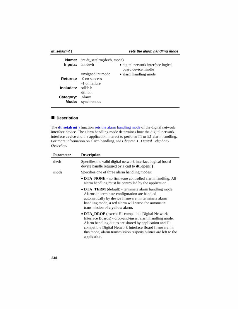
dt_setalrm( ) sets the alarm handling mode
int dt_setalrm(devh, mode) Name: Inputs: int devh • digital network interface logical
board device handle unsigned int mode • alarm handling mode
0 on success -1 on failure
Returns:
srllib.h dtilib.h
Includes:
Alarm Category: synchronous Mode:
Description
The dt_setalrm( ) function sets the alarm handling mode of the digital network interface device. The alarm handling mode determines how the digital network interface device and the application interact to perform T1 or E1 alarm handling. For more information on alarm handling, see Chapter 3. Digital Telephony Overview.
Parameter Description
devh Specifies the valid digital network interface logical board device handle returned by a call to dt_open( )
mode Specifies one of three alarm handling modes: • DTA_NONE - no firmware controlled alarm handling. All
alarm handling must be controlled by the application. • DTA_TERM (default) - terminate alarm handling mode.
Alarms in terminate configuration are handled automatically by device firmware. In terminate alarm handling mode, a red alarm will cause the automatic transmission of a yellow alarm.
• DTA_DROP (except E1 compatible Digital Network Interface Boards) - drop-and-insert alarm handling mode. Alarm handling duties are shared by application and T1 compatible Digital Network Interface Board firmware. In this mode, alarm transmission responsibilities are left to the application.
134
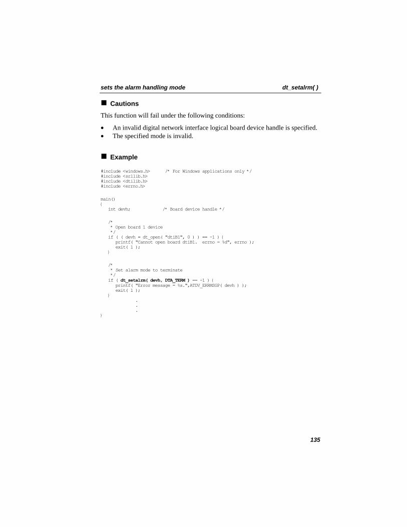
sets the alarm handling mode dt_setalrm( )
Cautions
This function will fail under the following conditions:
• An invalid digital network interface logical board device handle is specified. • The specified mode is invalid.
Example
#include <windows.h> /* For Windows applications only */ #include <srllib.h> #include <dtilib.h> #include <errno.h>
main() { int devh; /* Board device handle */
/* * Open board 1 device */ if ( ( devh = dt_open( "dtiB1", 0 ) ) == -1 ) { printf( "Cannot open board dtiB1. errno = %d", errno ); exit( 1 ); }
/* * Set alarm mode to terminate */ if ( dt_setalrm( devh, DTA_TERM ) == -1 ) { printf( "Error message = %s.",ATDV_ERRMSGP( devh ) ); exit( 1 ); } . . . }
135
dt_setalrm( ) sets the alarm handling mode
Errors
If the function returns -1, use the SRL Standard Attribute function ATDV_LASTERR( ) to obtain the error code or use ATDV_ERRMSGP( ) to obtain a descriptive error message. See Appendix A – Dialogic® Standard Runtime Library for more information on SRL functions. The error codes returned by ATDV_LASTERR( ) are:
• EDT_BADBRDERR - digital network interface missing or defective • EDT_BADCMDERR - invalid or undefined command to driver • EDT_BADVAL - invalid mode passed in parameter • EDT_DATTO - data reception timed out • EDT_FWERR - firmware returned an error • EDT_INVBD - invalid digital network interface logical board device handle • EDT_NOMEMERR - cannot map or allocate memory in driver • EDT_PARAMERR - invalid parameter • EDT_RANGEERR - bad/overlapping physical memory range • EDT_SIZERR - message too big or too small • EDT_SKIPRPLYERR - a required reply was skipped • EDT_SYSTEM - system error - check the global variable errno for more
information about the error • EDT_TMOERR - timed out waiting for reply from firmware
Error defines can be found in the file dtilib.h.
See Also
• dt_xmitalrm( )
136
enables and disables notification for events dt_setevtmsk( )
dt_setevtmsk(devh,event,bitmask,action) Name: Inputs: int devh • digital network interface
logical board or digital network interface logical time slot device handle
int event • event to be enabled/disabled unsigned short bitmask • bitmask for events int action • set, add, or subtract bitmask
0 on success -1 on failure
Returns:
srllib.h dtilib.h
Includes:
Parameter Setting Category: synchronous Mode:
Description
The dt_setevtmsk( ) function enables and disables notification for events that occur on a digital network interface logical board or time slot device. This function allows the application to set and alter a bitmask of transition events. The bitmask determines which transitions will cause an event to be generated.
The event can be retrieved by using the event management functions included in the Standard Runtime Library (refer to Appendix A – Dialogic® Standard Runtime Library for more information on the SRL). The current bitmask can be examined by using the dt_getevtmsk( ) function.
Parameter Description
devh Specifies the valid digital network interface logical board or digital network interface logical time slot device handle returned by a call to dt_open( )
event Specifies the type of event to be enabled or disabled on the device specified by devh:
• DTG_T1ERREVT - T1 error events (T1-compatible digital network interface logical board device handles only). Several T1 error events can be monitored. Specific T1 error events are enabled or disabled by setting the bitmask parameter.
137
dt_setevtmsk( ) enables and disables notification for events
Parameter
Description
• DTG_E1ERREVT - E1 error events (E1-compatible digital network interface logical board device handles only). Several E1 error events can be monitored. Specific E1 error events are enabled or disabled by setting the bitmask parameter.
• DTG_SIGEVT - Signaling bit transition events (time slot device handles only). Specific signaling events are enabled or disabled by setting the bitmask parameter.
• DTG_PDIGEVT - pulse digit events (Dialogic®
D/xxxSC Board time slot device handles only).
NOTE: For Dialogic® D/xxxSC Boards, you must enable both the ON and OFF transitions on a specified bit to get events on that bit. For example, AON and AOFF must be enabled to detect events on the A bit.
bitmask Specifies the event to be enabled or disabled by setting the bitmask for that event.
Multiple transition events may be enabled or disabled with one function call if the bitmask values are logically ORed together. The bitmask values for each event parameter are described in Table 5, found in the dt_getevtmsk( ) function description.
action Specifies how the signaling bit transition event mask is changed. Events can be added to or subtracted from those specified in bitmask, or events can replace the existing ones. The possible values for the action parameter are:
• DTA_SETMSK - enable notification of events specified in bitmask and disable notification of previously set events
• DTA_ADDMSK - enable notification of events specified in bitmask in addition to previously set events (not valid for DTG_PDIGEVT)
• DTA_SUBMSK - disable notification of events specified in bitmask
138
enables and disables notification for events dt_setevtmsk( )
For example, to enable event notification:
1. Specify the events to enable in the bitmask field.
2. Specify the DTA_SETMSK bitmask in the action field.
This enables notification of the events specified in the bitmask parameter and disables notification of previously set events.
To enable an additional event:
1. Specify the events in bitmask.
2. Specify DTA_ADDMSK in the action field.
This adds the notification of events specified in bitmask without disabling the currently enabled events.
To disable events, use the following procedure:
1. Specify the events in bitmask.
2. Specify DTA_SUBMSK in the action field.
This disables the event in bitmask without disabling any other events.
To disable all currently enabled events:
1. Specify 0 in bitmask.
2. Specify DTA_SETMSK in the action field.
Event Notification and Handling
NOTE: Event handling operations vary with the mode type (i.e., callback, polled, synchronous, etc.) used by your application. For more information on application development models, refer to the Dialogic®
Standard Runtime Library API Programming Guide.
139
dt_setevtmsk( ) enables and disables notification for events
To trap and handle a specified digital network interface event, follow these steps in the order listed:
1. Call sr_enbhdlr( ) - This function specifies the event and the application defined event handler that is called when this event occurs.
2. Call dt_setevtmsk( ) - This specifies the list of events for which the application should be notified.
NOTE: When the DTG_T1ERREVT, DTG_E1ERREVT, or DTG_SIGEVT event is generated, call the sr_getevtdatap( ) function in the event handler to get a pointer to the event value. The pointer should be cast to an unsigned short pointer and the event retrieved as an unsigned short value.
Refer to Appendix A – Dialogic® Standard Runtime Library for more information on SRL data structures and functions.
Cautions
1. This function will fail under the following conditions:
• An invalid time slot or an invalid digital network interface logical board device handle is specified.
• The event specified is invalid. • The action specified is invalid.
2. For the application to process an event, the SRL sr_enbhdlr( ) Event Management function should be called prior to calling the dt_setevtmsk( ) function.
3. When a wink event occurs, the signaling bits associated with the wink will be reported to the application. Therefore, your application’s signaling event handlers must make sure that any transition of the selected wink signaling bit is not part of a wink event.
140
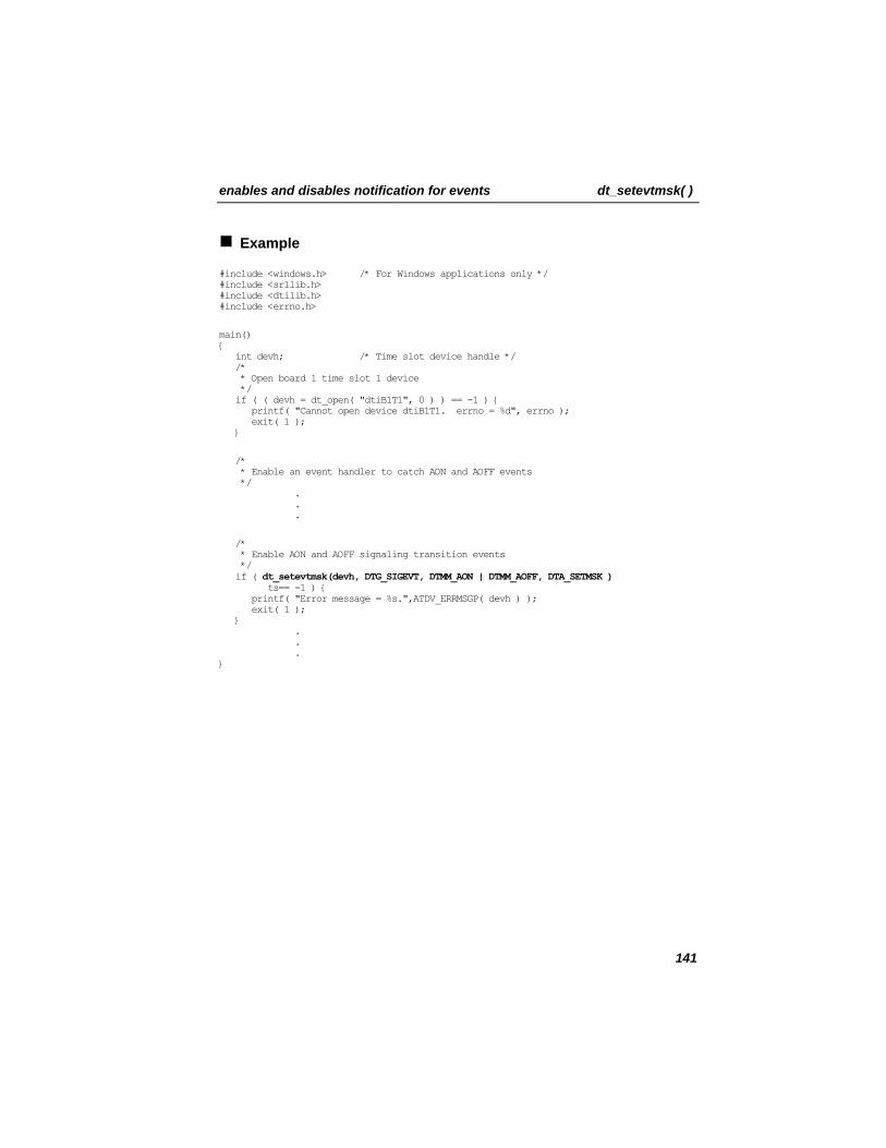
enables and disables notification for events dt_setevtmsk( )
Example
#include <windows.h> /* For Windows applications only */ #include <srllib.h> #include <dtilib.h> #include <errno.h>
main() { int devh; /* Time slot device handle */ /* * Open board 1 time slot 1 device */ if ( ( devh = dt_open( "dtiB1T1", 0 ) ) == -1 ) { printf( "Cannot open device dtiB1T1. errno = %d", errno ); exit( 1 ); }
/* * Enable an event handler to catch AON and AOFF events */ . . .
/* * Enable AON and AOFF signaling transition events */ if ( dt_setevtmsk(devh, DTG_SIGEVT, DTMM_AON | DTMM_AOFF, DTA_SETMSK ) ts== -1 ) { printf( "Error message = %s.",ATDV_ERRMSGP( devh ) ); exit( 1 ); } . . . }
141
dt_setevtmsk( ) enables and disables notification for events
Errors
If the function returns -1, use the SRL Standard Attribute function ATDV_LASTERR( ) to obtain the error code or use ATDV_ERRMSGP( ) to obtain a descriptive error message. See Appendix A – Dialogic® Standard Runtime Library for more information on SRL functions. The error codes returned by ATDV_LASTERR( ) are:
• EDT_BADBRDERR - digital network interface missing or defective • EDT_BADCMDERR - invalid or undefined command to driver • EDT_DATTO - data reception timed out • EDT_FWERR - firmware returned an error • EDT_INVBD - invalid digital network interface logical board device handle • EDT_INVTS - invalid digital network interface logical time slot device
handle • EDT_NOMEMERR - cannot map or allocate memory in driver • EDT_PARAMERR - invalid parameter • EDT_RANGEERR - bad/overlapping physical memory range • EDT_SIZERR - message too big or too small • EDT_SKIPRPLYERR - a required reply was skipped • EDT_SYSTEM - system error - check the global variable errno for more
information about the error • EDT_TMOERR - timed out waiting for reply from firmware
Error defines can be found in the file dtilib.h.
See Also
• dt_getevtmsk( ) • sr_enbhdlr( ) • sr_dishdlr( )
142
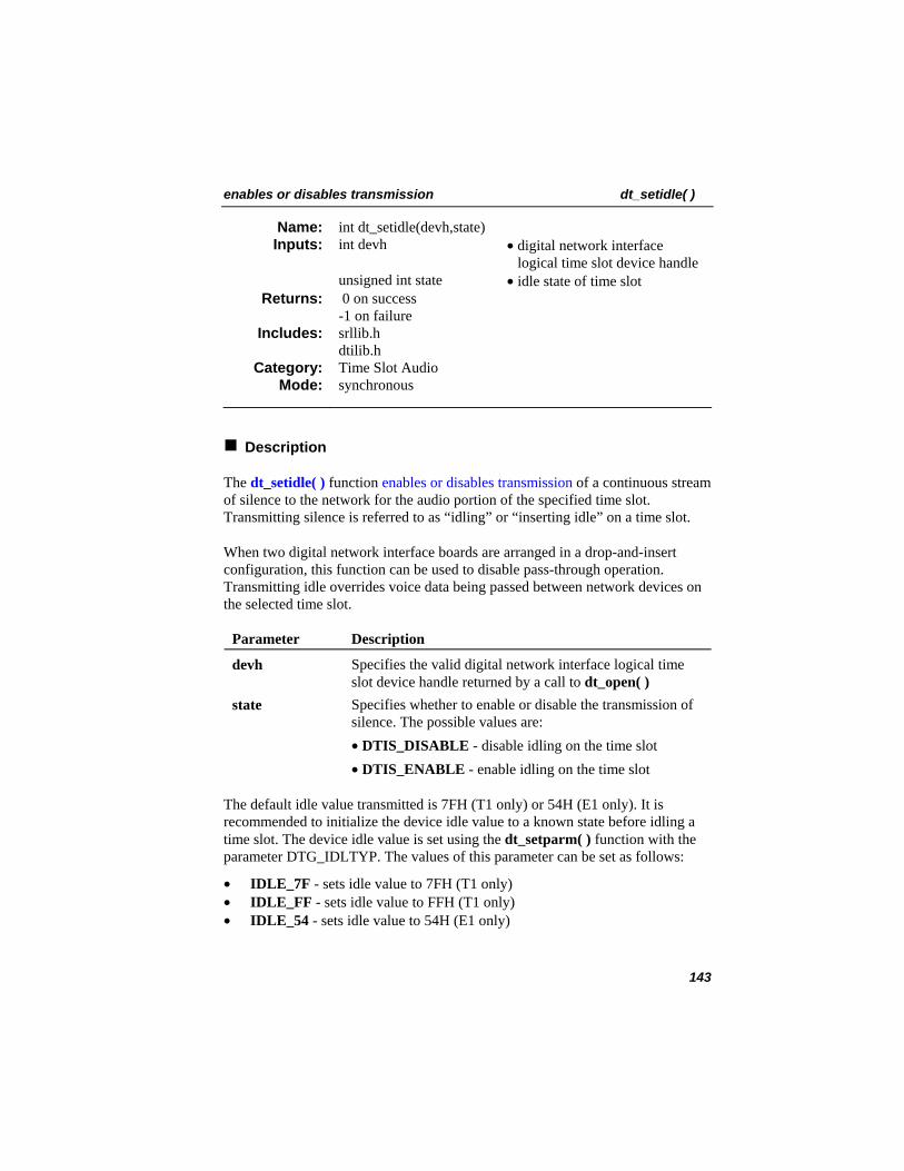
enables or disables transmission dt_setidle( )
int dt_setidle(devh,state) Name: Inputs: int devh • digital network interface
logical time slot device handle unsigned int state • idle state of time slot
0 on success -1 on failure
Returns:
srllib.h dtilib.h
Includes:
Time Slot Audio Category: synchronous Mode:
Description
The dt_setidle( ) function enables or disables transmission of a continuous stream of silence to the network for the audio portion of the specified time slot. Transmitting silence is referred to as “idling” or “inserting idle” on a time slot.
When two digital network interface boards are arranged in a drop-and-insert configuration, this function can be used to disable pass-through operation. Transmitting idle overrides voice data being passed between network devices on the selected time slot.
Parameter Description
devh Specifies the valid digital network interface logical time slot device handle returned by a call to dt_open( )
state Specifies whether to enable or disable the transmission of silence. The possible values are:
• DTIS_DISABLE - disable idling on the time slot • DTIS_ENABLE - enable idling on the time slot
The default idle value transmitted is 7FH (T1 only) or 54H (E1 only). It is recommended to initialize the device idle value to a known state before idling a time slot. The device idle value is set using the dt_setparm( ) function with the parameter DTG_IDLTYP. The values of this parameter can be set as follows:
• IDLE_7F - sets idle value to 7FH (T1 only) • IDLE_FF - sets idle value to FFH (T1 only) • IDLE_54 - sets idle value to 54H (E1 only)
143
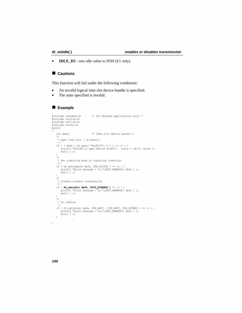
dt_setidle( ) enables or disables transmission
• IDLE_D5 - sets idle value to D5H (E1 only)
Cautions
This function will fail under the following conditions:
• An invalid logical time slot device handle is specified. • The state specified is invalid.
Example
#include <windows.h> /* For Windows applications only */ #include <srllib.h> #include <dtilib.h> #include <errno.h> main() { int devh; /* Time slot device handle */ /* * Open time slot 1 on board 1 */ if ( ( devh = dt_open( "dtiB1T1", 0 ) ) == -1 ) { printf( "Failed to open device dtiB1T1. errno = %d\n", errno ); exit( 1 ); } /* * Set signaling mode to signaling insertion */ if ( dt_setsigmod( devh, DTM_SIGINS ) == -1 ) { printf( "Error message = %s.",ATDV_ERRMSGP( devh ) ); exit( 1 ); } /* * Disable silence transmission */ if ( dt_setidle( devh, DTIS_DISABLE ) == -1 ) { printf( "Error message = %s.",ATDV_ERRMSGP( devh ) ); exit( 1 ); } /* * Go offhook */ if ( dt_settssig( devh, DTB_ABIT | DTB_BBIT, DTA_SETMSK ) == -1 ) { printf( "Error message = %s.",ATDV_ERRMSGP( devh ) ); exit( 1 ); } . }
144
enables or disables transmission dt_setidle( )
Errors
If the function returns -1, use the SRL Standard Attribute function ATDV_LASTERR( ) to obtain the error code or use ATDV_ERRMSGP( ) to obtain a descriptive error message. See Appendix A – Dialogic® Standard Runtime Library for more information on SRL functions. The error codes returned by ATDV_LASTERR( ) are:
• EDT_BADBRDERR - digital network interface missing or defective • EDT_BADCMDERR - invalid or undefined command to driver • EDT_DATTO - data reception timed out • EDT_FWERR - firmware returned an error • EDT_INVTS - invalid digital network interface logical time slot device
handle • EDT_NOMEMERR - cannot map or allocate memory in driver • EDT_PARAMERR - invalid parameter • EDT_RANGEERR - bad/overlapping physical memory range • EDT_SIZERR - message too big or too small • EDT_SKIPRPLYERR - a required reply was skipped • EDT_SYSTEM - system error - check the global variable errno for more
information about the error • EDT_TMOERR - timed out waiting for reply from firmware
Error defines can be found in the file dtilib.h.
See Also
• ATDT_IDLEST( ) • dt_setsigmod( )
145
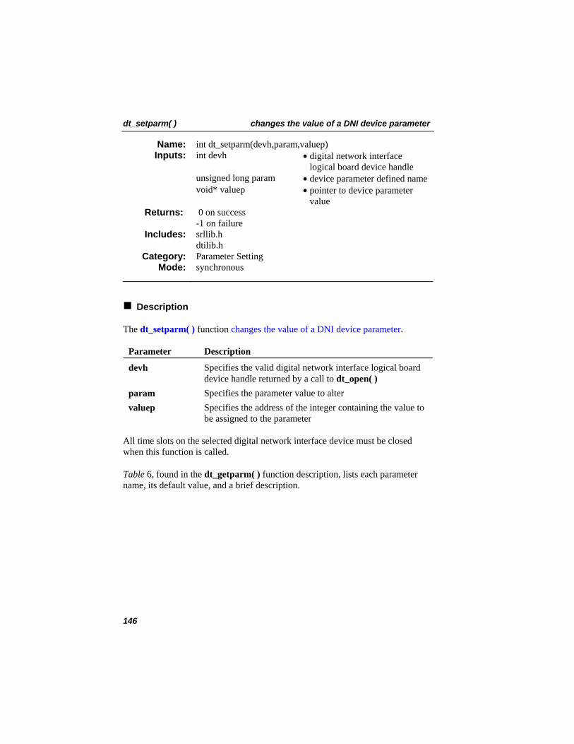
dt_setparm( ) changes the value of a DNI device parameter
int dt_setparm(devh,param,valuep) Name: Inputs: int devh • digital network interface
logical board device handle unsigned long param • device parameter defined name void* valuep • pointer to device parameter
value 0 on success -1 on failure
Returns:
srllib.h dtilib.h
Includes:
Parameter Setting Category: synchronous Mode:
Description
The dt_setparm( ) function changes the value of a DNI device parameter. Parameter Description
devh Specifies the valid digital network interface logical board device handle returned by a call to dt_open( )
param Specifies the parameter value to alter valuep Specifies the address of the integer containing the value to
be assigned to the parameter
All time slots on the selected digital network interface device must be closed when this function is called.
Table 6, found in the dt_getparm( ) function description, lists each parameter name, its default value, and a brief description.
146
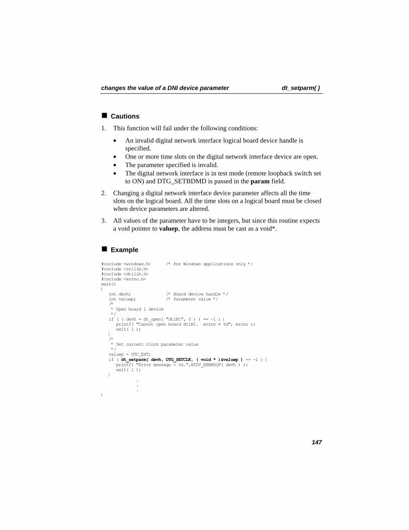
changes the value of a DNI device parameter dt_setparm( )
Cautions
1. This function will fail under the following conditions:
• An invalid digital network interface logical board device handle is specified.
• One or more time slots on the digital network interface device are open. • The parameter specified is invalid. • The digital network interface is in test mode (remote loopback switch set
to ON) and DTG_SETBDMD is passed in the param field.
2. Changing a digital network interface device parameter affects all the time slots on the logical board. All the time slots on a logical board must be closed when device parameters are altered.
3. All values of the parameter have to be integers, but since this routine expects a void pointer to valuep, the address must be cast as a void*.
Example
#include <windows.h> /* For Windows applications only */ #include <srllib.h> #include <dtilib.h> #include <errno.h> main() { int devh; /* Board device handle */ int valuep; /* Parameter value */ /* * Open board 1 device */ if ( ( devh = dt_open( "dtiB1", 0 ) ) == -1 ) { printf( "Cannot open board dtiB1. errno = %d", errno ); exit( 1 ); } /* * Set current clock parameter value */ valuep = DTC_EXT; if ( dt_setparm( devh, DTG_SETCLK, ( void * )&valuep ) == -1 ) { printf( "Error message = %s.",ATDV_ERRMSGP( devh ) ); exit( 1 ); } . . . }
147
dt_setparm( ) changes the value of a DNI device parameter
Errors
If the function returns -1, use the SRL Standard Attribute function ATDV_LASTERR( ) to obtain the error code or use ATDV_ERRMSGP( ) to obtain a descriptive error message. See Appendix A – Dialogic® Standard Runtime Library for more information on SRL functions. The error codes returned by ATDV_LASTERR( ) are:
• EDT_BADBRDERR - digital network interface missing or defective • EDT_BADCMDERR - invalid or undefined command to driver • EDT_BADGLOB - invalid param • EDT_BADVAL - invalid parameter value passed in valuep pointer • EDT_DATTO - data reception timed out • EDT_FWERR - firmware returned an error • EDT_INVBD - invalid digital network interface logical board device handle • EDT_NOCLK - no clock source present • EDT_NOIDLEERR - time slot not in idle/closed state • EDT_NOMEMERR - cannot map or allocate memory in driver • EDT_PARAMERR - invalid parameter • EDT_RANGEERR - bad/overlapping physical memory range • EDT_SIZERR - message too big or too small • EDT_SKIPRPLYERR - a required reply was skipped • EDT_SYSTEM - system error - check the global variable errno for more
information about the error • EDT_TMOERR - timed out waiting for reply from firmware • EDT_TSTMOD - in test mode; cannot set digital network interface mode
Error defines can be found in the file dtilib.h.
See Also
• dt_getparm( )
148
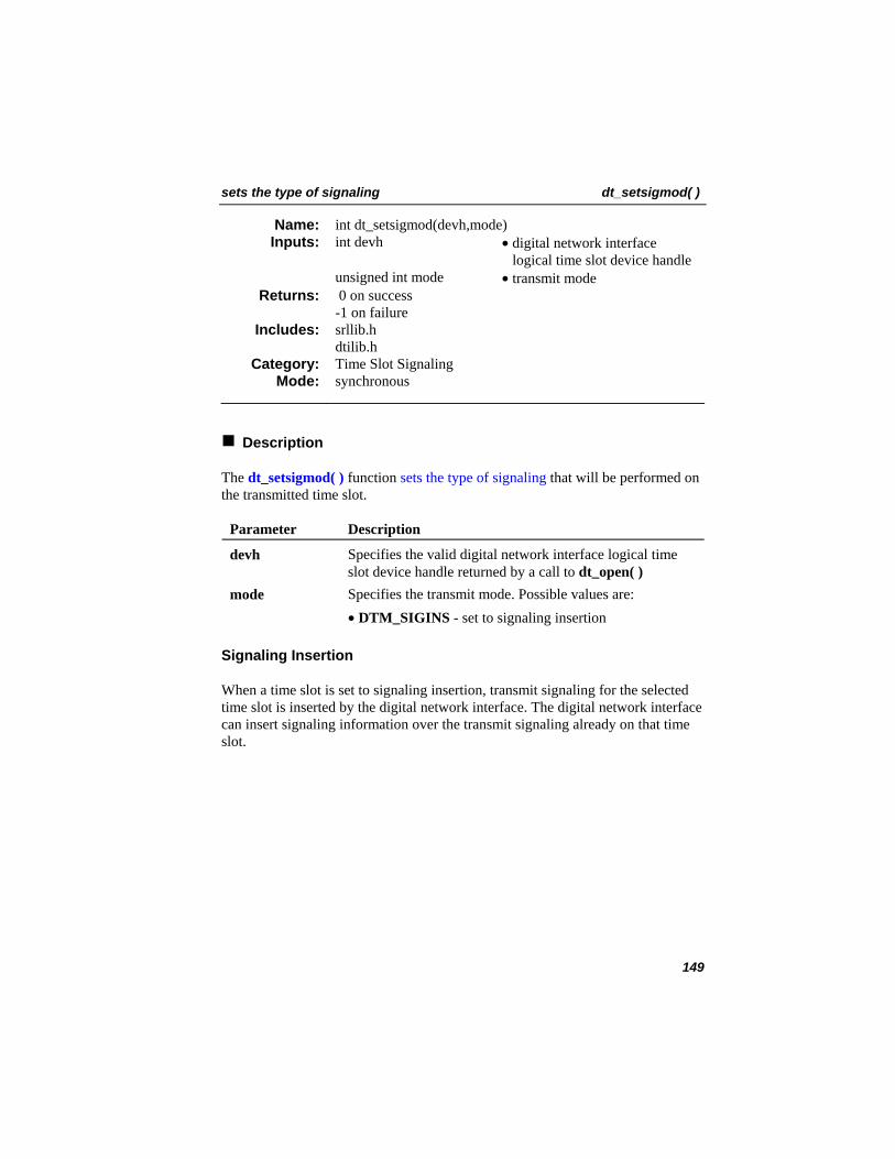
sets the type of signaling dt_setsigmod( )
int dt_setsigmod(devh,mode) Name: Inputs: int devh • digital network interface
logical time slot device handle unsigned int mode • transmit mode
0 on success -1 on failure
Returns:
srllib.h dtilib.h
Includes:
Time Slot Signaling Category: synchronous Mode:
Description
The dt_setsigmod( ) function sets the type of signaling that will be performed on the transmitted time slot.
Parameter Description
devh Specifies the valid digital network interface logical time slot device handle returned by a call to dt_open( )
mode Specifies the transmit mode. Possible values are: • DTM_SIGINS - set to signaling insertion
Signaling Insertion
When a time slot is set to signaling insertion, transmit signaling for the selected time slot is inserted by the digital network interface. The digital network interface can insert signaling information over the transmit signaling already on that time slot.
149
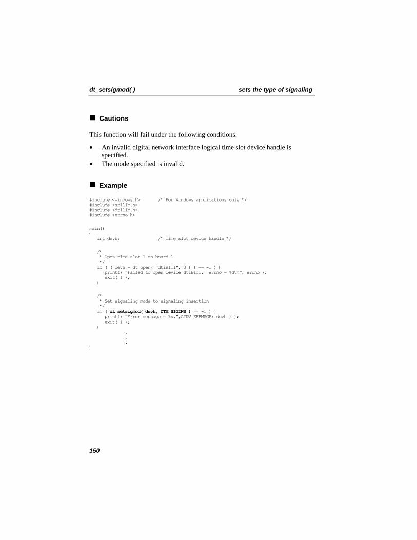
dt_setsigmod( ) sets the type of signaling
Cautions
This function will fail under the following conditions:
• An invalid digital network interface logical time slot device handle is specified.
• The mode specified is invalid.
Example
#include <windows.h> /* For Windows applications only */ #include <srllib.h> #include <dtilib.h> #include <errno.h>
main() { int devh; /* Time slot device handle */
/* * Open time slot 1 on board 1 */ if ( ( devh = dt_open( "dtiB1T1", 0 ) ) == -1 ) { printf( "Failed to open device dtiB1T1. errno = %d\n", errno ); exit( 1 ); }
/* * Set signaling mode to signaling insertion */ if ( dt_setsigmod( devh, DTM_SIGINS ) == -1 ) { printf( "Error message = %s.",ATDV_ERRMSGP( devh ) ); exit( 1 ); } . . . }
150
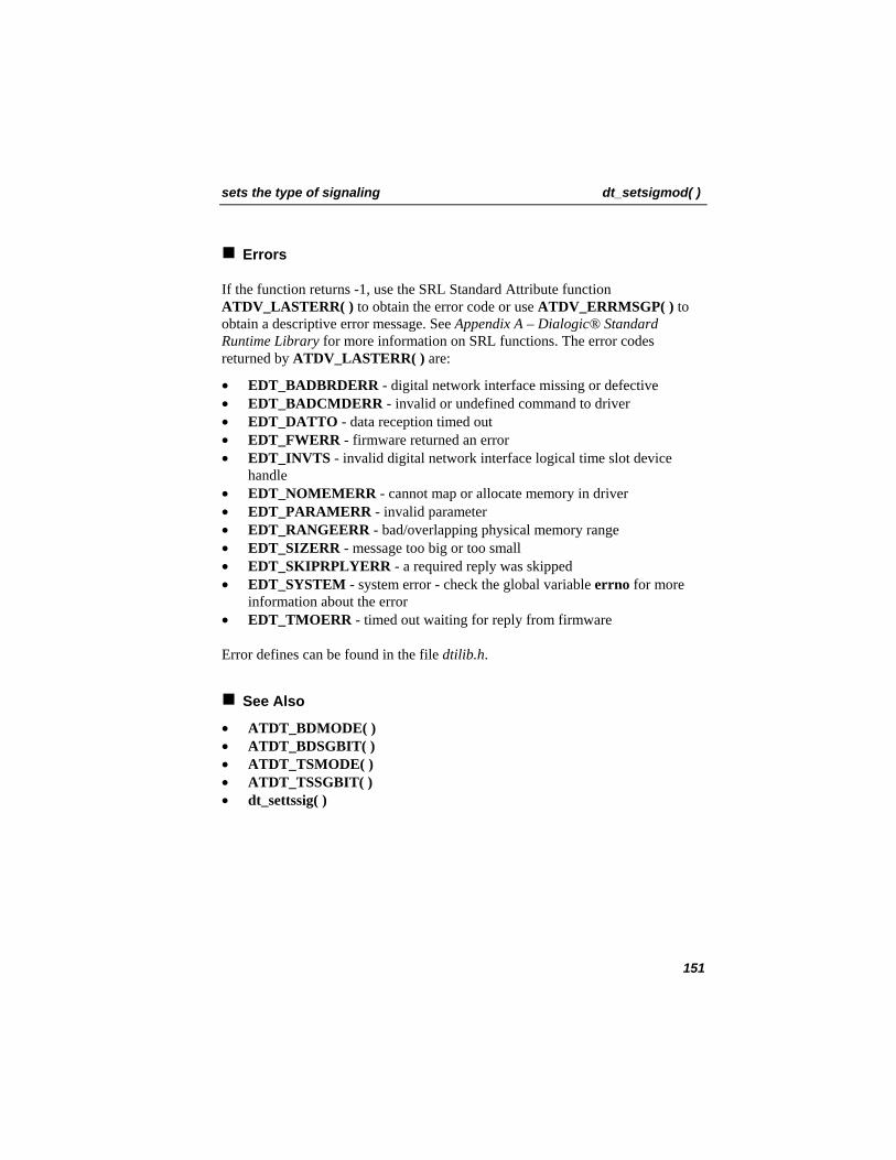
sets the type of signaling dt_setsigmod( )
Errors
If the function returns -1, use the SRL Standard Attribute function ATDV_LASTERR( ) to obtain the error code or use ATDV_ERRMSGP( ) to obtain a descriptive error message. See Appendix A – Dialogic® Standard Runtime Library for more information on SRL functions. The error codes returned by ATDV_LASTERR( ) are:
• EDT_BADBRDERR - digital network interface missing or defective • EDT_BADCMDERR - invalid or undefined command to driver • EDT_DATTO - data reception timed out • EDT_FWERR - firmware returned an error • EDT_INVTS - invalid digital network interface logical time slot device
handle • EDT_NOMEMERR - cannot map or allocate memory in driver • EDT_PARAMERR - invalid parameter • EDT_RANGEERR - bad/overlapping physical memory range • EDT_SIZERR - message too big or too small • EDT_SKIPRPLYERR - a required reply was skipped • EDT_SYSTEM - system error - check the global variable errno for more
information about the error • EDT_TMOERR - timed out waiting for reply from firmware
Error defines can be found in the file dtilib.h.
See Also
• ATDT_BDMODE( ) • ATDT_BDSGBIT( ) • ATDT_TSMODE( ) • ATDT_TSSGBIT( ) • dt_settssig( )
151
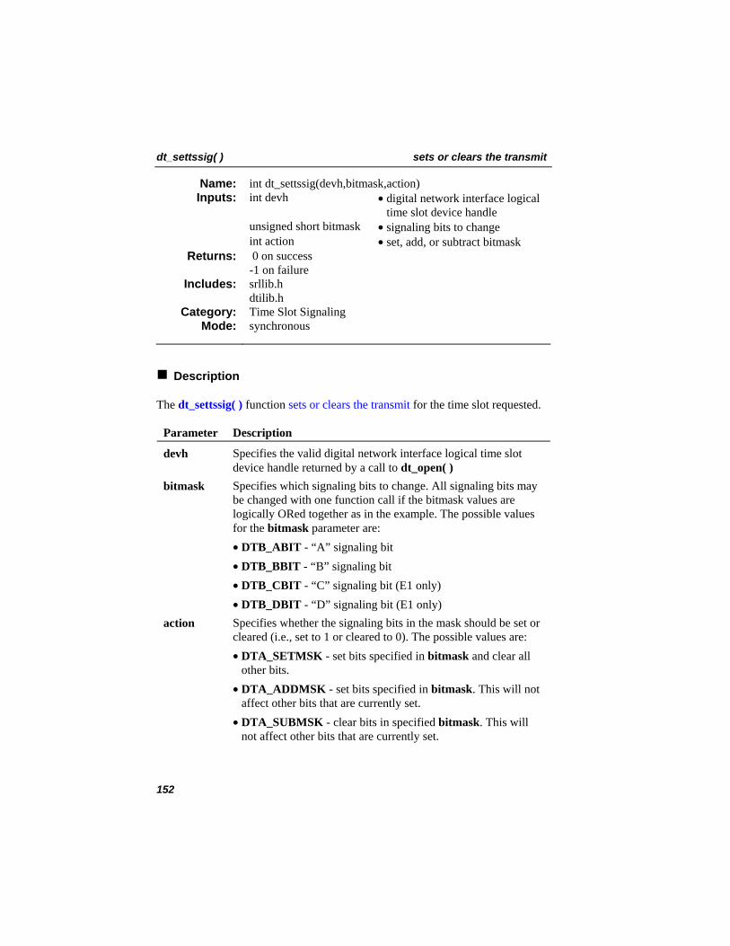
dt_settssig( ) sets or clears the transmit
int dt_settssig(devh,bitmask,action) Name: Inputs: int devh • digital network interface logical
time slot device handle unsigned short bitmask • signaling bits to change int action • set, add, or subtract bitmask
0 on success -1 on failure
Returns:
srllib.h dtilib.h
Includes:
Time Slot Signaling Category: synchronous Mode:
Description
The dt_settssig( ) function sets or clears the transmit for the time slot requested. Parameter Description
devh Specifies the valid digital network interface logical time slot device handle returned by a call to dt_open( )
bitmask Specifies which signaling bits to change. All signaling bits may be changed with one function call if the bitmask values are logically ORed together as in the example. The possible values for the bitmask parameter are:
• DTB_ABIT - “A” signaling bit • DTB_BBIT - “B” signaling bit • DTB_CBIT - “C” signaling bit (E1 only) • DTB_DBIT - “D” signaling bit (E1 only) action Specifies whether the signaling bits in the mask should be set or
cleared (i.e., set to 1 or cleared to 0). The possible values are: • DTA_SETMSK - set bits specified in bitmask and clear all
other bits. • DTA_ADDMSK - set bits specified in bitmask. This will not
affect other bits that are currently set. • DTA_SUBMSK - clear bits in specified bitmask. This will
not affect other bits that are currently set.
152
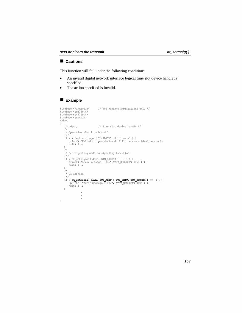
sets or clears the transmit dt_settssig( )
Cautions
This function will fail under the following conditions:
• An invalid digital network interface logical time slot device handle is specified.
• The action specified is invalid.
Example
#include <windows.h> /* For Windows applications only */ #include <srllib.h> #include <dtilib.h> #include <errno.h> main() { int devh; /* Time slot device handle */ /* * Open time slot 1 on board 1 */ if ( ( devh = dt_open( "dtiB1T1", 0 ) ) == -1 ) { printf( "Failed to open device dtiB1T1. errno = %d\n", errno ); exit( 1 ); } /* * Set signaling mode to signaling insertion */ if ( dt_setsigmod( devh, DTM_SIGINS ) == -1 ) { printf( "Error message = %s.",ATDV_ERRMSGP( devh ) ); exit( 1 ); } /* * Go offhook */ if ( dt_settssig( devh, DTB_ABIT | DTB_BBIT, DTA_SETMSK ) == -1 ) { printf( "Error message = %s.", ATDV_ERRMSGP( devh ) ); exit( 1 ); } . . . }
153
dt_settssig( ) sets or clears the transmit
Errors
If the function returns -1, use the SRL Standard Attribute function ATDV_LASTERR( ) to obtain the error code or use ATDV_ERRMSGP( ) to obtain a descriptive error message. See Appendix A – Dialogic® Standard Runtime Library for more information on SRL functions. The error codes returned by ATDV_LASTERR( ) are:
• EDT_BADBRDERR - digital network interface missing or defective • EDT_BADCMDERR - invalid or undefined command to driver • EDT_DATTO - data reception timed out • EDT_FWERR - firmware returned an error • EDT_INVTS - invalid digital network interface logical time slot device
handle • EDT_NOMEMERR - cannot map or allocate memory in driver • EDT_PARAMERR - invalid parameter • EDT_RANGEERR - bad/overlapping physical memory range • EDT_SIZERR - message too big or too small • EDT_SKIPRPLYERR - a required reply was skipped • EDT_SYSTEM - system error - check the global variable errno for more
information about the error • EDT_TMOERR - timed out waiting for reply from firmware
Error defines can be found in the file dtilib.h.
See Also
• ATDT_BDMODE( ) • ATDT_BDSGBIT( ) • ATDT_TSMODE( ) • ATDT_TSSGBIT( ) • dt_setsigmod( )
154
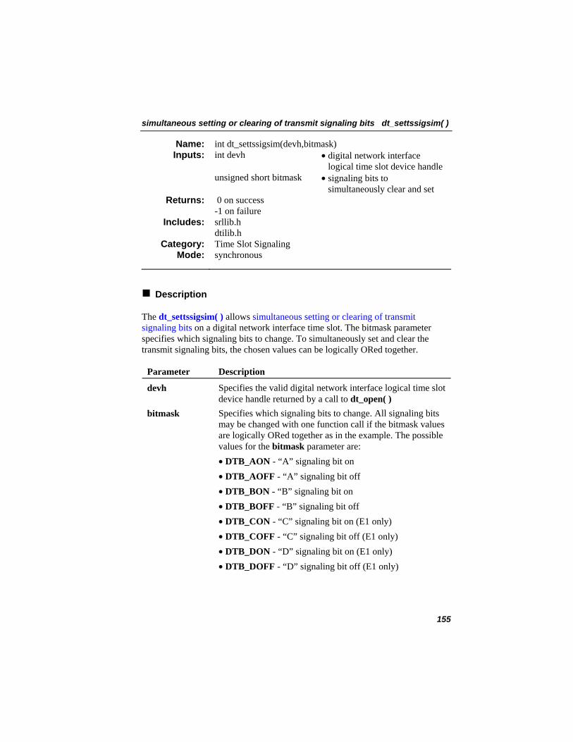
simultaneous setting or clearing of transmit signaling bits dt_settssigsim( )
int dt_settssigsim(devh,bitmask) Name: Inputs: int devh • digital network interface
logical time slot device handle unsigned short bitmask • signaling bits to
simultaneously clear and set 0 on success -1 on failure
Returns:
srllib.h dtilib.h
Includes:
Time Slot Signaling Category: synchronous Mode:
Description
The dt_settssigsim( ) allows simultaneous setting or clearing of transmit signaling bits on a digital network interface time slot. The bitmask parameter specifies which signaling bits to change. To simultaneously set and clear the transmit signaling bits, the chosen values can be logically ORed together.
Parameter Description
devh Specifies the valid digital network interface logical time slot device handle returned by a call to dt_open( )
bitmask Specifies which signaling bits to change. All signaling bits may be changed with one function call if the bitmask values are logically ORed together as in the example. The possible values for the bitmask parameter are:
• DTB_AON - “A” signaling bit on • DTB_AOFF - “A” signaling bit off • DTB_BON - “B” signaling bit on • DTB_BOFF - “B” signaling bit off • DTB_CON - “C” signaling bit on (E1 only) • DTB_COFF - “C” signaling bit off (E1 only) • DTB_DON - “D” signaling bit on (E1 only) • DTB_DOFF - “D” signaling bit off (E1 only)
155
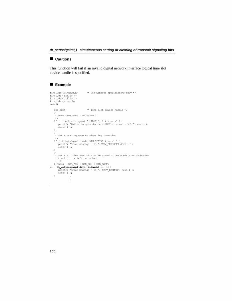
dt_settssigsim( ) simultaneous setting or clearing of transmit signaling bits
Cautions
This function will fail if an invalid digital network interface logical time slot device handle is specified.
Example
#include <windows.h> /* For Windows applications only */ #include <srllib.h> #include <dtilib.h> #include <errno.h> main() { int devh; /* Time slot device handle */ /* * Open time slot 1 on board 1 */ if ( ( devh = dt_open( "dtiB1T1", 0 ) ) == -1 ) { printf( "Failed to open device dtiB1T1. errno = %d\n", errno ); exit( 1 ); } /* * Set signaling mode to signaling insertion */ if ( dt_setsigmod( devh, DTM_SIGINS ) == -1 ) { printf( "Error message = %s.",ATDV_ERRMSGP( devh ) ); exit( 1 ); } /* * Set A & C time slot bits while clearing the B bit simultaneously * the D bit is left untouched * / bitmask = DTB_AON | DTB_CON | DTB_BOFF; if ( dt_settssigsim( devh, bitmask) == -1) { printf( "Error message = %s.", ATDV_ERRMSGP( devh ) ); exit( 1 ); } . . . }
156
simultaneous setting or clearing of transmit signaling bits dt_settssigsim( )
Errors
If the function returns -1, use the SRL Standard Attribute function ATDV_LASTERR( ) to obtain the error code or use ATDV_ERRMSGP( ) to obtain a descriptive error message. See Appendix A – Dialogic® Standard Runtime Library for more information on SRL functions. The error codes returned by ATDV_LASTERR( ) are:
• EDT_BADBRDERR - digital network interface missing or defective • EDT_BADCMDERR - invalid or undefined command to driver • EDT_DATTO - data reception timed out • EDT_FWERR - firmware returned an error • EDT_INVTS - invalid digital network interface logical time slot device
handle • EDT_NOMEMERR - cannot map or allocate memory in driver • EDT_PARAMERR - invalid parameter • EDT_RANGEERR - bad/overlapping physical memory range • EDT_SIZERR - message too big or too small • EDT_SKIPRPLYERR - a required reply was skipped • EDT_SYSTEM - system error - check the global variable errno for more
information about the error • EDT_TMOERR - timed out waiting for reply from firmware
Error defines can be found in the file dtilib.h.
See Also
• ATDT_BDMODE( ) • ATDT_BDSGBIT( ) • ATDT_TSMODE( ) • ATDT_TSSGBIT( ) • dt_setsigmod( )
157
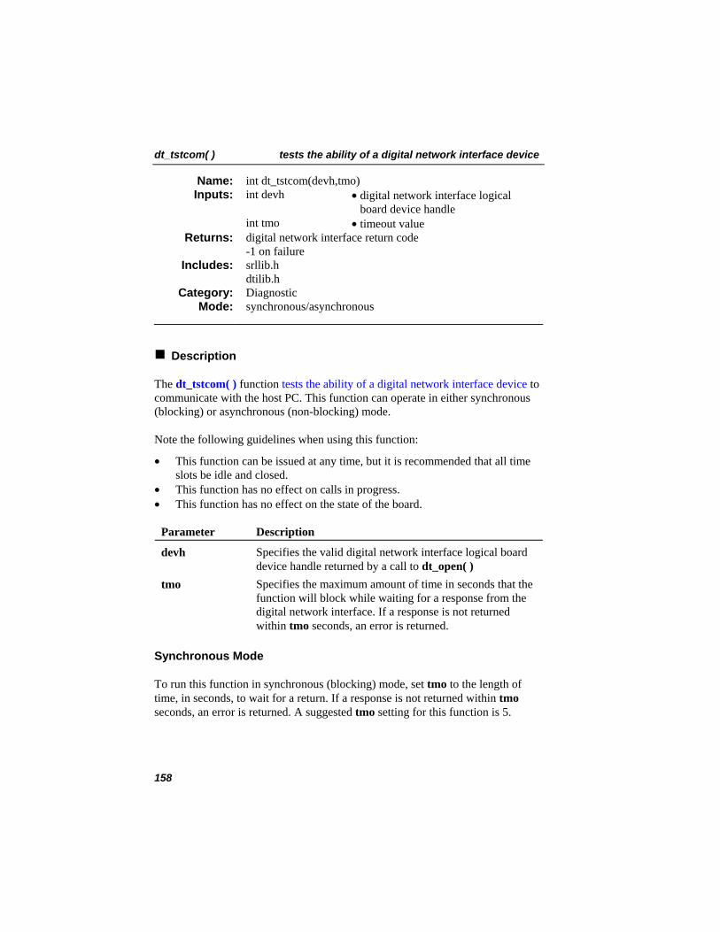
dt_tstcom( ) tests the ability of a digital network interface device
int dt_tstcom(devh,tmo) Name: Inputs: int devh • digital network interface logical
board device handle int tmo • timeout value
digital network interface return code -1 on failure
Returns:
srllib.h dtilib.h
Includes:
Diagnostic Category: synchronous/asynchronous Mode:
Description
The dt_tstcom( ) function tests the ability of a digital network interface device to communicate with the host PC. This function can operate in either synchronous (blocking) or asynchronous (non-blocking) mode.
Note the following guidelines when using this function:
• This function can be issued at any time, but it is recommended that all time slots be idle and closed.
• This function has no effect on calls in progress. • This function has no effect on the state of the board.
Parameter Description
devh Specifies the valid digital network interface logical board device handle returned by a call to dt_open( )
tmo Specifies the maximum amount of time in seconds that the function will block while waiting for a response from the digital network interface. If a response is not returned within tmo seconds, an error is returned.
Synchronous Mode
To run this function in synchronous (blocking) mode, set tmo to the length of time, in seconds, to wait for a return. If a response is not returned within tmo seconds, an error is returned. A suggested tmo setting for this function is 5.
158
tests the ability of a digital network interface device dt_tstcom( )
Asynchronous Mode
To operate this function in asynchronous (non-blocking) mode, specify 0 for tmo. This allows the application to continue processing while waiting for a completion event. If event handling is set up properly for your application, DTEV_COMRSP will be returned by the sr_getevttype( ) function included in the SRL when the test is successfully completed. See Appendix A – Dialogic® Standard Runtime Library for information on event handling.
Cautions
1. This function returns a failure under the following conditions:
• The specified device fails to respond within tmo seconds, if operating in synchronous mode.
• A time slot or invalid digital network interface logical device handle is specified.
• There is a hardware problem on the digital network interface. • There is a configuration problem (for example, IRQ conflict).
NOTE: Device configuration information is found in the appropriate hardware installation card.
2. To use this function in asynchronous mode, you must use the SRL sr_enbhdlr( ) function to enable trapping of events and create an event handler to process the completion event returned by the device.
The event can be detected by using the event management functions included in the Dialogic® Standard Runtime Library. See Appendix A – Dialogic® Standard Runtime Library for more information on digital network interface event management.
159
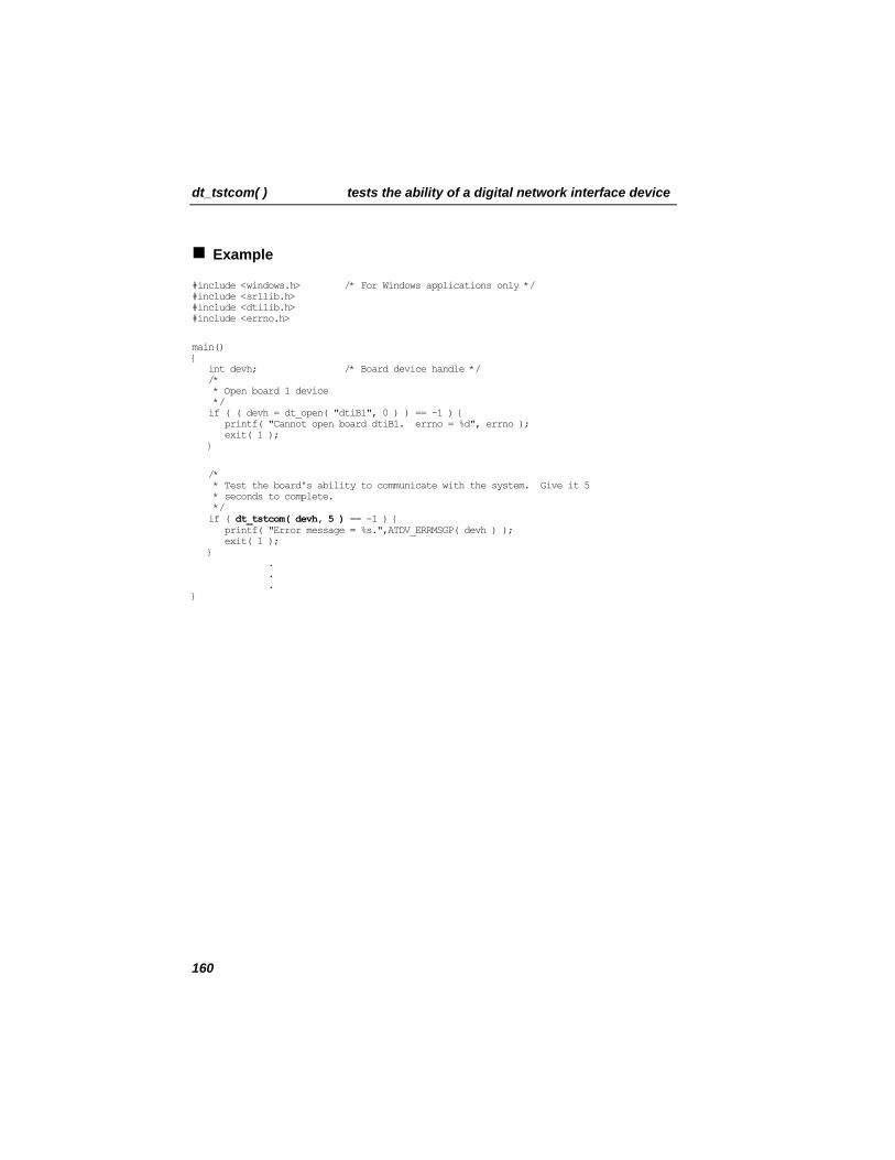
dt_tstcom( ) tests the ability of a digital network interface device
Example
#include <windows.h> /* For Windows applications only */ #include <srllib.h> #include <dtilib.h> #include <errno.h>
main() { int devh; /* Board device handle */ /* * Open board 1 device */ if ( ( devh = dt_open( "dtiB1", 0 ) ) == -1 ) { printf( "Cannot open board dtiB1. errno = %d", errno ); exit( 1 ); }
/* * Test the board's ability to communicate with the system. Give it 5 * seconds to complete. */ if ( dt_tstcom( devh, 5 ) == -1 ) { printf( "Error message = %s.",ATDV_ERRMSGP( devh ) ); exit( 1 ); } . . . }
160
tests the ability of a digital network interface device dt_tstcom( )
Errors
If the function returns -1, use the SRL Standard Attribute function ATDV_LASTERR( ) to obtain the error code or use ATDV_ERRMSGP( ) to obtain a descriptive error message. See Appendix A – Dialogic® Standard Runtime Library for more information on SRL functions. The error codes returned by ATDV_LASTERR( ) are:
• EDT_BADBRDERR - digital network interface missing or defective • EDT_BADCMDERR - invalid or undefined command to driver • EDT_DATTO - data reception timed out • EDT_FWERR - firmware returned an error • EDT_INVBD - invalid digital network interface logical board device handle • EDT_NOMEMERR - cannot map or allocate memory in driver • EDT_PARAMERR - invalid parameter • EDT_RANGEERR - bad/overlapping physical memory range • EDT_SIZERR - message too big or too small • EDT_SKIPRPLYERR - a required reply was skipped • EDT_SYSTEM - system error - check the global variable errno for more
information about the error • EDT_TMOERR - timed out waiting for reply from firmware
Error defines can be found in the file dtilib.h.
See Also
• dt_tstdat( ) • dt_rundiag( )
161
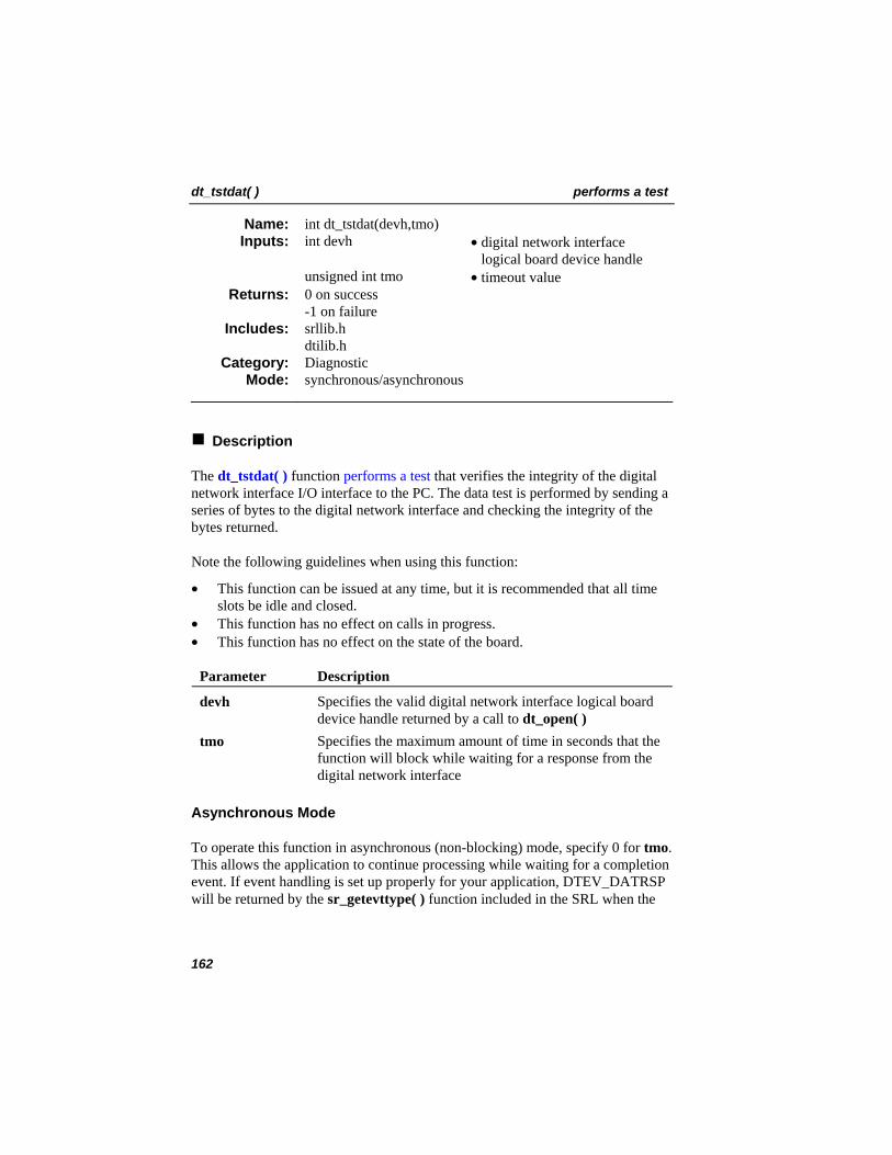
dt_tstdat( ) performs a test
int dt_tstdat(devh,tmo) Name: Inputs: int devh • digital network interface
logical board device handle unsigned int tmo • timeout value
0 on success -1 on failure
Returns:
srllib.h dtilib.h
Includes:
Diagnostic Category: synchronous/asynchronous Mode:
Description
The dt_tstdat( ) function performs a test that verifies the integrity of the digital network interface I/O interface to the PC. The data test is performed by sending a series of bytes to the digital network interface and checking the integrity of the bytes returned.
Note the following guidelines when using this function:
• This function can be issued at any time, but it is recommended that all time slots be idle and closed.
• This function has no effect on calls in progress. • This function has no effect on the state of the board.
Parameter Description
devh Specifies the valid digital network interface logical board device handle returned by a call to dt_open( )
tmo Specifies the maximum amount of time in seconds that the function will block while waiting for a response from the digital network interface
Asynchronous Mode
To operate this function in asynchronous (non-blocking) mode, specify 0 for tmo. This allows the application to continue processing while waiting for a completion event. If event handling is set up properly for your application, DTEV_DATRSP will be returned by the sr_getevttype( ) function included in the SRL when the
162
performs a test dt_tstdat( )
test is successfully completed. See Appendix A – Dialogic® Standard Runtime Library for information on event handling.
Synchronous Mode
To run this function in synchronous (blocking) mode, set tmo to the length of time, in seconds, to wait for a return. If a response is not returned within tmo seconds, an error is returned. A suggested tmo setting for this function is 5.
Cautions
1. This function returns a failure under the following conditions:
• The test data is corrupted. • A time slot or invalid digital network interface logical board device
handle is specified.
2. To use this function in asynchronous mode, you must use the SRL sr_enbhdlr( ) function to enable trapping of events and create an event handler to process the completion event returned by the device. The event can be detected by using the SRL event management functions. See Appendix A – Dialogic® Standard Runtime Library for more information on digital network interface event management.
163
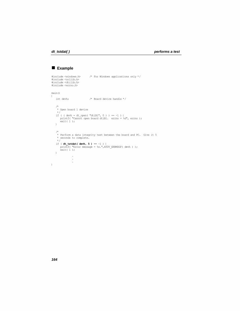
dt_tstdat( ) performs a test
Example
#include <windows.h> /* For Windows applications only */ #include <srllib.h> #include <dtilib.h> #include <errno.h>
main() { int devh; /* Board device handle */
/* * Open board 1 device */ if ( ( devh = dt_open( "dtiB1", 0 ) ) == -1 ) { printf( "Cannot open board dtiB1. errno = %d", errno ); exit( 1 ); }
/* * Perform a data integrity test between the board and PC. Give it 5 * seconds to complete. */ if ( dt_tstdat( devh, 5 ) == -1 ) { printf( "Error message = %s.",ATDV_ERRMSGP( devh ) ); exit( 1 ); } . . . }
164

performs a test dt_tstdat( )
Errors
If the function returns -1, use the SRL Standard Attribute function ATDV_LASTERR( ) to obtain the error code or use ATDV_ERRMSGP( ) to obtain a descriptive error message. See Appendix A – Dialogic® Standard Runtime Library for more information on SRL functions. The error codes returned by ATDV_LASTERR( ) are:
• EDT_BADBRDERR - digital network interface missing or defective • EDT_BADCMDERR - invalid or undefined command to driver • EDT_DATTO - data reception timed out • EDT_FWERR - firmware returned an error • EDT_INVBD - invalid digital network interface logical board device handle • EDT_NOMEMERR - cannot map or allocate memory in driver • EDT_PARAMERR - invalid parameter • EDT_RANGEERR - bad/overlapping physical memory range • EDT_SIZERR - message too big or too small • EDT_SKIPRPLYERR - a required reply was skipped • EDT_SYSTEM - system error - check the global variable errno for more
information about the error • EDT_TMOERR - timed out waiting for reply from firmware
Error defines can be found in the file dtilib.h.
See Also
• dt_tstcom( ) • dt_rundiag( )
165
dt_unlisten( ) disconnects the receive channel
dt_unlisten(devh) Name: Inputs: int devh • digital network interface
device time slot 0 on success -1 on error
Returns:
srllib.h dtilib.h
Includes:
SCbus Routing Category: synchronous Mode:
Description
The dt_unlisten( ) function disconnects the receive channel from the SCbus. This function disconnects the digital receive (listen) channel (T1/E1 time slot) such as on a Dialogic® D/240SC-T1 or D/300SC-E1 Board from the SCbus time slot.
Calling the dt_listen( ) function to connect to a different SCbus time slot will automatically break an existing connection. Therefore, when changing connections, you need not call the dt_unlisten( ) function.
NOTE: The SCbus convenience function nr_scunroute( ) includes dt_unlisten( ) functionality; see the Dialogic Voice API Library Referenc
®
e. Parameter Description
devh Specifies a valid digital network interface time slot device handle returned by a call to dt_open( )
Cautions
This function will fail if an invalid time slot device handle is specified.
166
disconnects the receive channel dt_unlisten( )
Example
#include <windows.h> /* For Windows applications only */ #include <srllib.h> #include <dtilib.h> #include <errno.h>
main( ) { int devh; /* Digital channel (time slot) device handle */
/* Open board 1 time slot 1 device */ if ((devh = dt_open("dtiB1T1", 0)) == -1) { printf("Cannot open time slot dtiB1T1. errno = %d", errno); exit(1); }
/* Disconnect receive of board 1, time slot 1 from all SCbus time slots */ if (dt_unlisten(devh) == -1) { printf("Error message = %s", ATDV_ERRMSGP(devh)); exit(1); } }
167
dt_unlisten( ) disconnects the receive channel
Errors
If the function returns -1, use the SRL Standard Attribute function ATDV_LASTERR( ) to obtain the error code or use ATDV_ERRMSGP( ) to obtain a descriptive error message. The error codes returned by ATDV_LASTERR( ) are:
• EDT_BADBRDERR - board missing or defective • EDT_BADCMDERR - invalid command parameter to driver • EDT_FWERR - firmware returned an error • EDT_INVTS - invalid time slot device handle • EDT_INVMSG - invalid message • EDT_SH_BADLCLTS - invalid local time slot number • EDT_SH_BADEXTTS - external time slot unsupported at current clock rate • EDT_SH_BADINDX - invalid switch handler library index number • EDT_SH_BADMODE - invalid switch handler bus configuration • EDT_SH_BADTYPE - invalid local time slot type • EDT_SH_LCLDSCNCT - local time slot is already disconnected from
SCbus • EDT_SH_LIBBSY - switch handler library busy • EDT_SH_LIBNOTINIT - switch handler library is uninitialized • EDT_SH_MISSING - switch handler is not present • EDT_SH_NOCLK - switch handler clock fallback failed • EDT_SYSTEM - system error • EDT_TMOERR - timed out waiting for reply from firmware
See Also
• dt_listen( )
168
starts and stops transmission of an alarm dt_xmitalrm( )
int dt_xmitalrm(devh, alrmtype, state) Name: Inputs: int devh • digital network interface
logical board device handle unsigned char alrmtype • T1 or E1 alarm type unsigned int state • enable or disable sending the
alarm 0 on success -1 on failure
Returns:
srllib.h dtilib.h
Includes:
Alarm Category: synchronous Mode:
Description
The dt_xmitalrm( ) function starts and stops transmission of an alarm to a network span. For a detailed description of T1 and E1 alarm handling, refer to Chapter 3. Digital Telephony Overview.
Parameter Description
devh Specifies the valid digital network interface logical board device handle returned by a call to dt_open( )
alrmtype Specifies the T1 or E1 alarm type to be transmitted: • YELLOW - T1 only • BLUE - T1 only • DEA_REMOTE - E1 only • DEA_UNFRAMED1 (unframed all 1s) - E1 only • DEA_SIGNALALL1 (signaling all 1s) - E1 only • DEA_DISTANTMF (distant multiframe alarm) - E1
only state Specifies whether to enable or disable transmission of the
specified alarm: • DTIS_DISABLE - disable transmission of alarm • DTIS_ENABLE - enable transmission of alarm
169
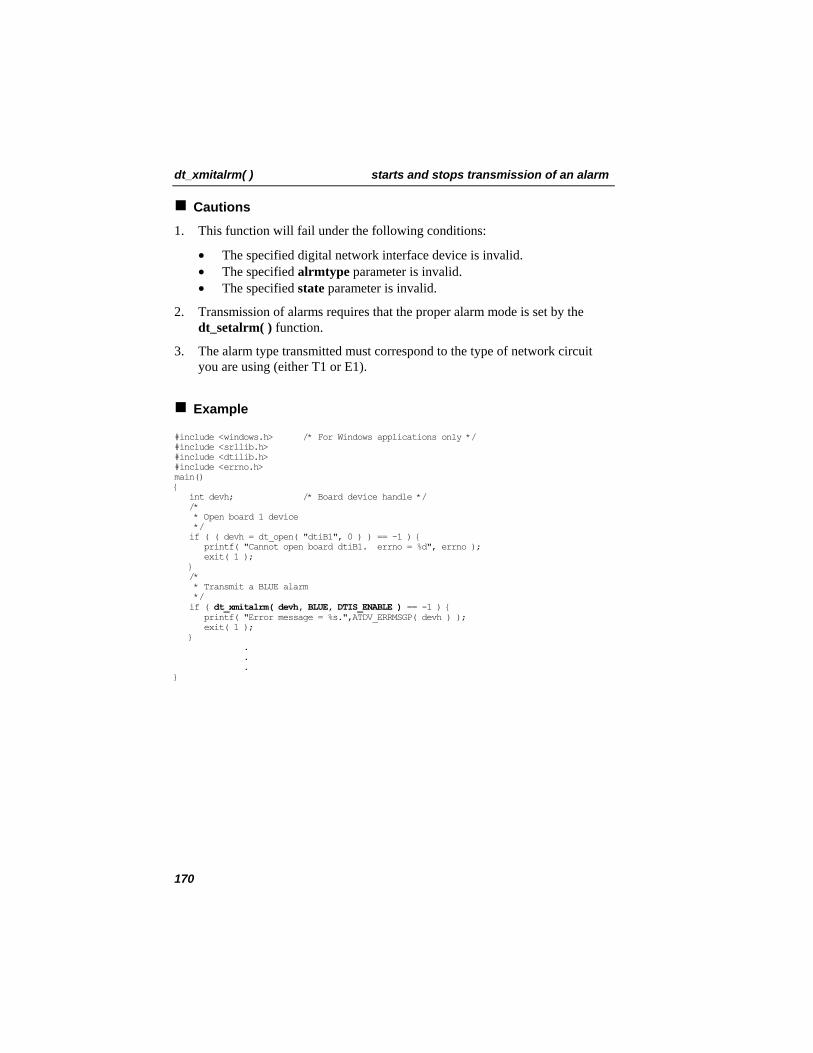
dt_xmitalrm( ) starts and stops transmission of an alarm
Cautions
1. This function will fail under the following conditions:
• The specified digital network interface device is invalid. • The specified alrmtype parameter is invalid. • The specified state parameter is invalid.
2. Transmission of alarms requires that the proper alarm mode is set by the dt_setalrm( ) function.
3. The alarm type transmitted must correspond to the type of network circuit you are using (either T1 or E1).
Example
#include <windows.h> /* For Windows applications only */ #include <srllib.h> #include <dtilib.h> #include <errno.h> main() { int devh; /* Board device handle */ /* * Open board 1 device */ if ( ( devh = dt_open( "dtiB1", 0 ) ) == -1 ) { printf( "Cannot open board dtiB1. errno = %d", errno ); exit( 1 ); } /* * Transmit a BLUE alarm */ if ( dt_xmitalrm( devh, BLUE, DTIS_ENABLE ) == -1 ) { printf( "Error message = %s.",ATDV_ERRMSGP( devh ) ); exit( 1 ); } . . . }
170
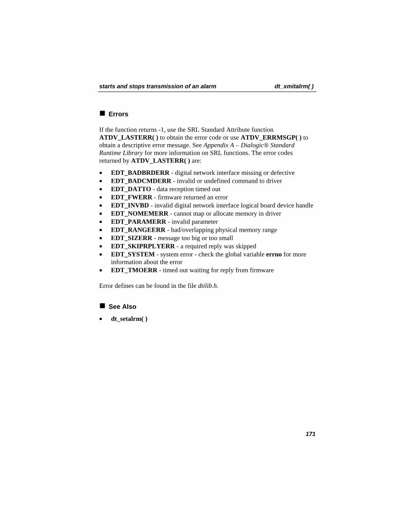
starts and stops transmission of an alarm dt_xmitalrm( )
Errors
If the function returns -1, use the SRL Standard Attribute function ATDV_LASTERR( ) to obtain the error code or use ATDV_ERRMSGP( ) to obtain a descriptive error message. See Appendix A – Dialogic® Standard Runtime Library for more information on SRL functions. The error codes returned by ATDV_LASTERR( ) are:
• EDT_BADBRDERR - digital network interface missing or defective • EDT_BADCMDERR - invalid or undefined command to driver • EDT_DATTO - data reception timed out • EDT_FWERR - firmware returned an error • EDT_INVBD - invalid digital network interface logical board device handle • EDT_NOMEMERR - cannot map or allocate memory in driver • EDT_PARAMERR - invalid parameter • EDT_RANGEERR - bad/overlapping physical memory range • EDT_SIZERR - message too big or too small • EDT_SKIPRPLYERR - a required reply was skipped • EDT_SYSTEM - system error - check the global variable errno for more
information about the error • EDT_TMOERR - timed out waiting for reply from firmware
Error defines can be found in the file dtilib.h.
See Also
• dt_setalrm( )
171
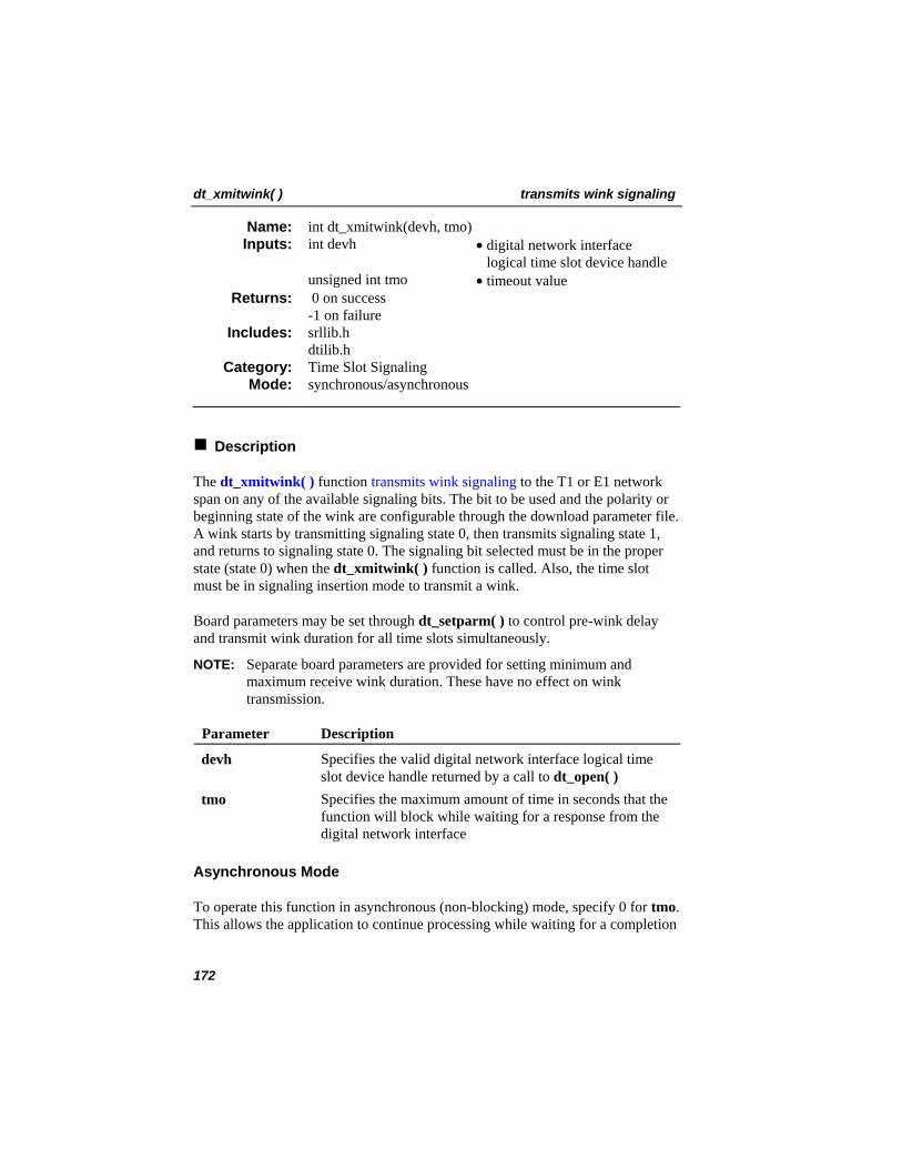
dt_xmitwink( ) transmits wink signaling
int dt_xmitwink(devh, tmo) Name: Inputs: int devh • digital network interface
logical time slot device handle unsigned int tmo • timeout value
0 on success -1 on failure
Returns:
srllib.h dtilib.h
Includes:
Time Slot Signaling Category: synchronous/asynchronous Mode:
Description
The dt_xmitwink( ) function transmits wink signaling to the T1 or E1 network span on any of the available signaling bits. The bit to be used and the polarity or beginning state of the wink are configurable through the download parameter file. A wink starts by transmitting signaling state 0, then transmits signaling state 1, and returns to signaling state 0. The signaling bit selected must be in the proper state (state 0) when the dt_xmitwink( ) function is called. Also, the time slot must be in signaling insertion mode to transmit a wink.
Board parameters may be set through dt_setparm( ) to control pre-wink delay and transmit wink duration for all time slots simultaneously.
NOTE: Separate board parameters are provided for setting minimum and maximum receive wink duration. These have no effect on wink transmission.
Parameter Description
devh Specifies the valid digital network interface logical time slot device handle returned by a call to dt_open( )
tmo Specifies the maximum amount of time in seconds that the function will block while waiting for a response from the digital network interface
Asynchronous Mode
To operate this function in asynchronous (non-blocking) mode, specify 0 for tmo. This allows the application to continue processing while waiting for a completion
172
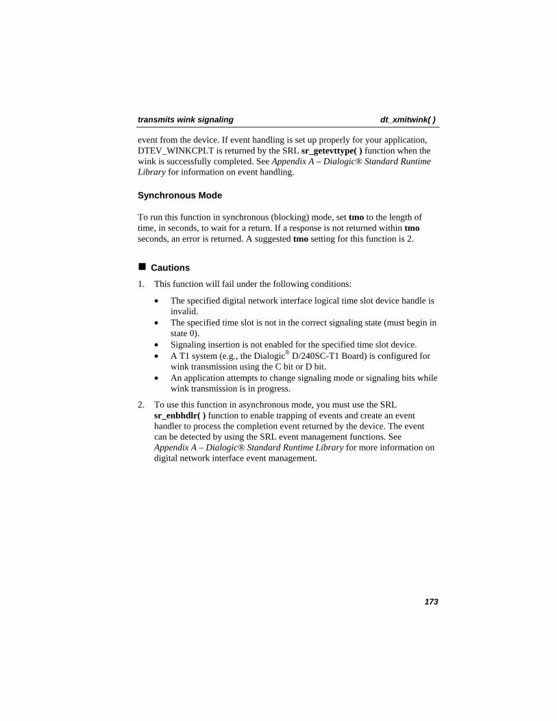
transmits wink signaling dt_xmitwink( )
event from the device. If event handling is set up properly for your application, DTEV_WINKCPLT is returned by the SRL sr_getevttype( ) function when the wink is successfully completed. See Appendix A – Dialogic® Standard Runtime Library for information on event handling.
Synchronous Mode
To run this function in synchronous (blocking) mode, set tmo to the length of time, in seconds, to wait for a return. If a response is not returned within tmo seconds, an error is returned. A suggested tmo setting for this function is 2.
Cautions
1. This function will fail under the following conditions:
• The specified digital network interface logical time slot device handle is invalid.
• The specified time slot is not in the correct signaling state (must begin in state 0).
• Signaling insertion is not enabled for the specified time slot device. • A T1 system (e.g., the Dialogic® D/240SC-T1 Board) is configured for
wink transmission using the C bit or D bit. • An application attempts to change signaling mode or signaling bits while
wink transmission is in progress.
2. To use this function in asynchronous mode, you must use the SRL sr_enbhdlr( ) function to enable trapping of events and create an event handler to process the completion event returned by the device. The event can be detected by using the SRL event management functions. See Appendix A – Dialogic® Standard Runtime Library for more information on digital network interface event management.
173
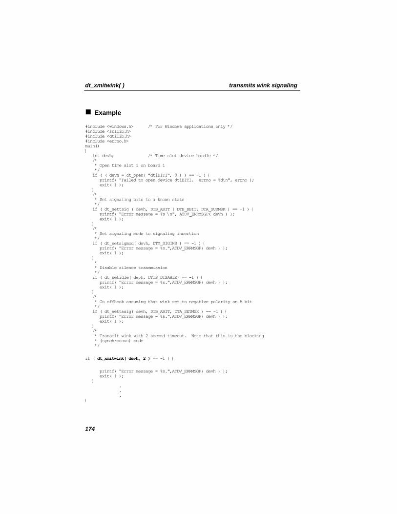
dt_xmitwink( ) transmits wink signaling
Example
#include <windows.h> /* For Windows applications only */ #include <srllib.h> #include <dtilib.h> #include <errno.h> main() { int devh; /* Time slot device handle */ /* * Open time slot 1 on board 1 */ if ( ( devh = dt_open( "dtiB1T1", 0 ) ) == -1 ) { printf( "Failed to open device dtiB1T1. errno = %d\n", errno ); exit( 1 ); } /* * Set signaling bits to a known state */ if ( dt_settsig ( devh, DTB_ABIT | DTB_BBIT, DTA_SUBMSK ) == -1 ) { printf( "Error message = %s \n", ATDV_ERRMSGP( devh ) ); exit( 1 ); } /* * Set signaling mode to signaling insertion */ if ( dt_setsigmod( devh, DTM_SIGINS ) == -1 ) { printf( "Error message = %s.",ATDV_ERRMSGP( devh ) ); exit( 1 ); } * * Disable silence transmission */ if ( dt_setidle( devh, DTIS_DISABLE) == -1 ) { printf( "Error message = %s.",ATDV_ERRMSGP( devh ) ); exit( 1 ); } /* * Go offhook assuming that wink set to negative polarity on A bit */ if ( dt_settssig( devh, DTB_ABIT, DTA_SETMSK ) == -1 ) { printf( "Error message = %s.",ATDV_ERRMSGP( devh ) ); exit( 1 ); } /* * Transmit wink with 2 second timeout. Note that this is the blocking * (synchronous) mode */
if ( dt_xmitwink( devh, 2 ) == -1 ) {
printf( "Error message = %s.",ATDV_ERRMSGP( devh ) ); exit( 1 ); } . . . }
174
transmits wink signaling dt_xmitwink( )
Errors
If the function returns -1, use the SRL Standard Attribute function ATDV_LASTERR( ) to obtain the error code or use ATDV_ERRMSGP( ) to obtain a descriptive error message. See Appendix A – Dialogic® Standard Runtime Library for more information. The error codes returned by ATDV_LASTERR( ) are:
• EDT_BADBRDERR - digital network interface missing or defective • EDT_BADCMDERR - invalid or undefined command to driver • EDT_DATTO - data reception timed out • EDT_FWERR - firmware returned an error • EDT_INVTS - invalid digital network interface logical time slot device
handle • EDT_NOMEMERR - cannot map or allocate memory in driver • EDT_PARAMERR - invalid parameter • EDT_PDOFFHK - wink bit not in correct initial state • EDT_RANGEERR - bad/overlapping physical memory range • EDT_SIGINS - signaling insertion not enabled • EDT_SIZERR - message too big or too small • EDT_SKIPRPLYERR - a required reply was skipped • EDT_SYSTEM - system error - check the global variable errno for more
information about the error • EDT_TMOERR - timed out waiting for reply from firmware • EDT_WKACT - already transmitting wink • EDT_WKSIG - cannot disable insertion when transmitting wink
Error defines can be found in the file dtilib.h.
See Also
• dt_setparm( ) • dt_setsigmod( ) • dt_settssig( )
175

6. Application Guidelines This chapter offers suggestions to guide programmers in designing and coding a digital network interface application.
6.1. Writing a Simple Application
This chapter is not meant to be a comprehensive guide to developing or debugging digital network interface applications. Instead, the following sections provide digital network interface general and task-specific programming guidelines:
• General guidelines • Initialization • Processing • Terminating • Compiling and linking • Aborting
6.1.1. General Guidelines
The following general guidelines for writing applications are explained in this section.
• Use symbolic defines • Include header files • Check return codes
Use Symbolic Defines
Do not use a numerical value in your application when an equivalent symbolic define is available.
Include Header Files
Various header files must be included in your application to test for error conditions, to use other library functions from this release, or to perform event management and standard attribute functions. An example is shown below. See Section 4.3. Include Files, for details.
177
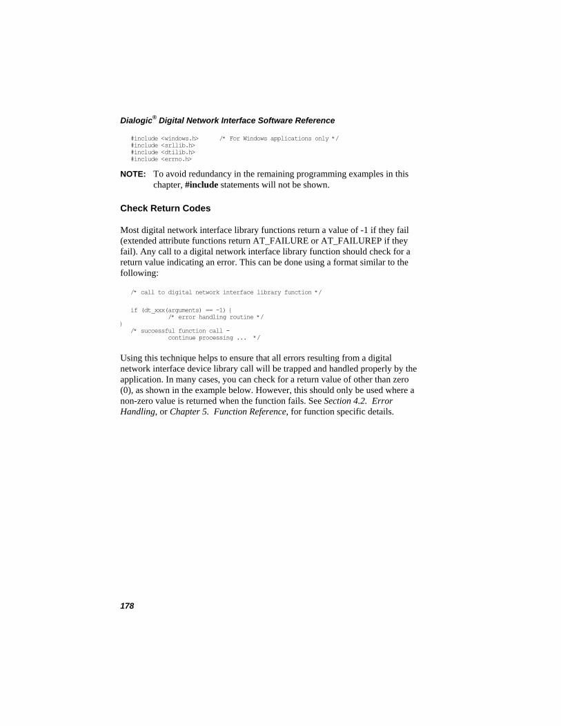
Dialogic® Digital Network Interface Software Reference
#include <windows.h> /* For Windows applications only */ #include <srllib.h> #include <dtilib.h> #include <errno.h>
NOTE: To avoid redundancy in the remaining programming examples in this chapter, #include statements will not be shown.
Check Return Codes
Most digital network interface library functions return a value of -1 if they fail (extended attribute functions return AT_FAILURE or AT_FAILUREP if they fail). Any call to a digital network interface library function should check for a return value indicating an error. This can be done using a format similar to the following:
/* call to digital network interface library function */
if (dt_xxx(arguments) == -1) { /* error handling routine */ } /* successful function call - continue processing ... */
Using this technique helps to ensure that all errors resulting from a digital network interface device library call will be trapped and handled properly by the application. In many cases, you can check for a return value of other than zero (0), as shown in the example below. However, this should only be used where a non-zero value is returned when the function fails. See Section 4.2. Error Handling, or Chapter 5. Function Reference, for function specific details.
178
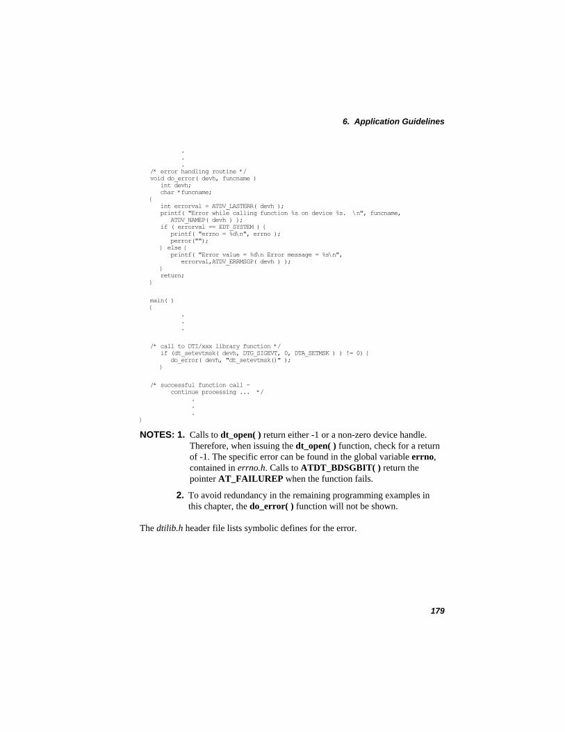
6. Application Guidelines
. . . /* error handling routine */ void do_error( devh, funcname ) int devh; char *funcname; { int errorval = ATDV_LASTERR( devh ); printf( "Error while calling function %s on device %s. \n", funcname, ATDV_NAMEP( devh ) ); if ( errorval == EDT_SYSTEM ) { printf( "errno = %d\n", errno ); perror(""); } else { printf( "Error value = %d\n Error message = %s\n", errorval,ATDV_ERRMSGP( devh ) ); } return; }
main( ) { . . .
/* call to DTI/xxx library function */ if (dt_setevtmsk( devh, DTG_SIGEVT, 0, DTA_SETMSK ) ) != 0) { do_error( devh, "dt_setevtmsk()" ); }
/* successful function call - continue processing ... */ . . . }
NOTES: 1. Calls to dt_open( ) return either -1 or a non-zero device handle. Therefore, when issuing the dt_open( ) function, check for a return of -1. The specific error can be found in the global variable errno, contained in errno.h. Calls to ATDT_BDSGBIT( ) return the pointer AT_FAILUREP when the function fails.
2. To avoid redundancy in the remaining programming examples in this chapter, the do_error( ) function will not be shown.
The dtilib.h header file lists symbolic defines for the error.
179
Dialogic® Digital Network Interface Software Reference
6.1.2. Initialization
Before a digital network interface application can perform any processing or access devices, it should initialize the digital network interface hardware to reflect the physical configuration of your system and set other parameters needed to support the application. Tasks that are performed as a part of initialization generally include:
• Set hardware configuration • Set alarm handling parameters and masks • Initialize time slots
These involve the following digital network interface device functions:
• dt_setalrm( ) • dt_setevtmsk( ) • dt_setidle( ) • dt_setparm( ) • dt_setsigmod( ) • dt_settssig( )
NOTE: Preferably, parameters set by dt_setparm( ) are those that must be changed while the application is running or that cannot be set through the download parameter file.
Set Hardware Configuration
Use dt_setparm( ) to set hardware configuration, test mode, clock source, and network telephony parameters. Specific settings include:
• Cable type connecting the digital network interface device to the network • Loopback test mode • Clock source (see dt_setparm( ) in Chapter 5. Function Reference for an
example) • Wink detection and transmission duration
180
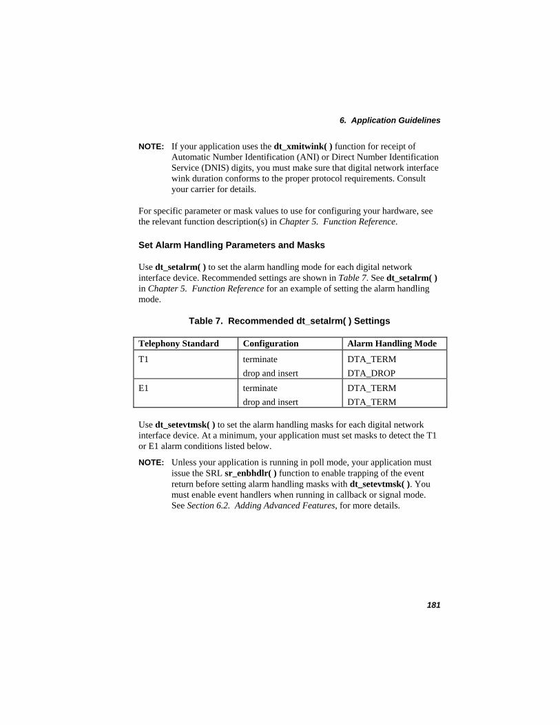
6. Application Guidelines
NOTE: If your application uses the dt_xmitwink( ) function for receipt of Automatic Number Identification (ANI) or Direct Number Identification Service (DNIS) digits, you must make sure that digital network interface wink duration conforms to the proper protocol requirements. Consult your carrier for details.
For specific parameter or mask values to use for configuring your hardware, see the relevant function description(s) in Chapter 5. Function Reference.
Set Alarm Handling Parameters and Masks
Use dt_setalrm( ) to set the alarm handling mode for each digital network interface device. Recommended settings are shown in Table 7. See dt_setalrm( ) in Chapter 5. Function Reference for an example of setting the alarm handling mode.
Table 7. Recommended dt_setalrm( ) Settings
Telephony Standard Configuration Alarm Handling Mode
T1 terminate DTA_TERM drop and insert DTA_DROP E1 terminate DTA_TERM drop and insert DTA_TERM
Use dt_setevtmsk( ) to set the alarm handling masks for each digital network interface device. At a minimum, your application must set masks to detect the T1 or E1 alarm conditions listed below.
NOTE: Unless your application is running in poll mode, your application must issue the SRL sr_enbhdlr( ) function to enable trapping of the event return before setting alarm handling masks with dt_setevtmsk( ). You must enable event handlers when running in callback or signal mode. See Section 6.2. Adding Advanced Features, for more details.
181
Dialogic® Digital Network Interface Software Reference
T1 alarms: • DTEC_B8ZSD - bipolar eight zero subs detection • DTEC_BPVS - bipolar violation count saturation • DTEC_BVCS - bipolar violation count saturation • DTEC_DPM - driver performance monitor restored • DTEC_ECS - error count saturation • DTEC_FERR - frame bit error • DTEC_LOS - loss of signal notification • DTEC_OOF - OOF condition mask • DTEC_RBL - receive blue alarm • DTEC_RCL - receive carrier loss • DTEC_RCLX - receive carrier loss • DTEC_RED - receive red alarm • DTEC_RLOS - receive loss of sync • DTEC_RYEL - receive yellow alarm
E1 alarms: • DEEC_BPVS - bipolar violation count saturation • DEEC_CECS - CRC4 error count saturation • DEEC_DPM - driver performance monitor • DEEC_ECS - error count saturation notification • DEEC_FSERR - frame sync error • DEEC_LOS - loss of signal notification • DEEC_MFSERR - multiframe sync error • DEEC_RDMA - receive distant multiframe alarm • DEEC_RLOS - receive loss of sync • DEEC_RRA - receive remote alarm • DEEC_RSA1 - receive signaling all 1s alarm • DEEC_RUA1 - receive unframed all 1s alarm
Initialize Time Slots
Before making or receiving any calls, an application should initialize all time slots to a known state. Initialization consists of:
• Clearing/setting all signaling event masks • Setting time slots to the idle state • Setting the proper signaling mode • Idling the time slots
182
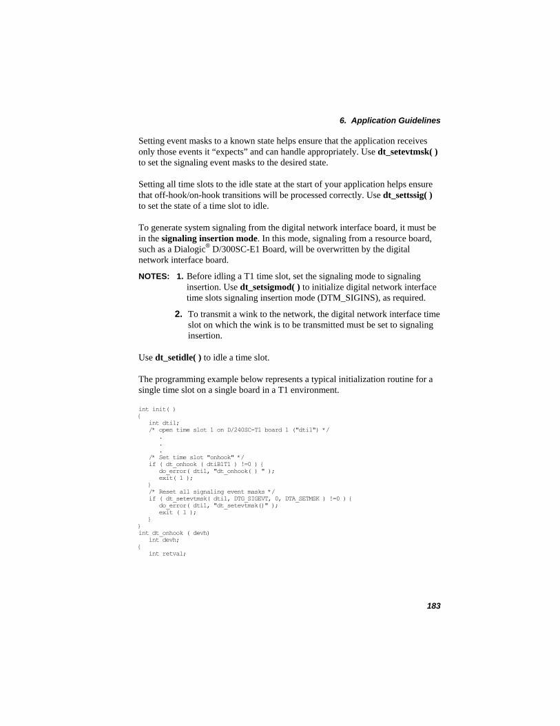
6. Application Guidelines
Setting event masks to a known state helps ensure that the application receives only those events it “expects” and can handle appropriately. Use dt_setevtmsk( ) to set the signaling event masks to the desired state.
Setting all time slots to the idle state at the start of your application helps ensure that off-hook/on-hook transitions will be processed correctly. Use dt_settssig( ) to set the state of a time slot to idle.
To generate system signaling from the digital network interface board, it must be in the signaling insertion mode. In this mode, signaling from a resource board, such as a Dialogic® D/300SC-E1 Board, will be overwritten by the digital network interface board.
NOTES: 1. Before idling a T1 time slot, set the signaling mode to signaling insertion. Use dt_setsigmod( ) to initialize digital network interface time slots signaling insertion mode (DTM_SIGINS), as required.
2. To transmit a wink to the network, the digital network interface time slot on which the wink is to be transmitted must be set to signaling insertion.
Use dt_setidle( ) to idle a time slot.
The programming example below represents a typical initialization routine for a single time slot on a single board in a T1 environment.
int init( ) { int dti1; /* open time slot 1 on D/240SC-T1 board 1 ("dti1") */ . . . /* Set time slot "onhook" */ if ( dt_onhook ( dtiB1T1 ) !=0 ) { do_error( dti1, "dt_onhook( ) " ); exit( 1 ); } /* Reset all signaling event masks */ if ( dt_setevtmsk( dti1, DTG_SIGEVT, 0, DTA_SETMSK ) !=0 ) { do_error( dti1, "dt_setevtmsk()" ); exit ( 1 ); } } int dt_onhook ( devh) int devh; { int retval;
183
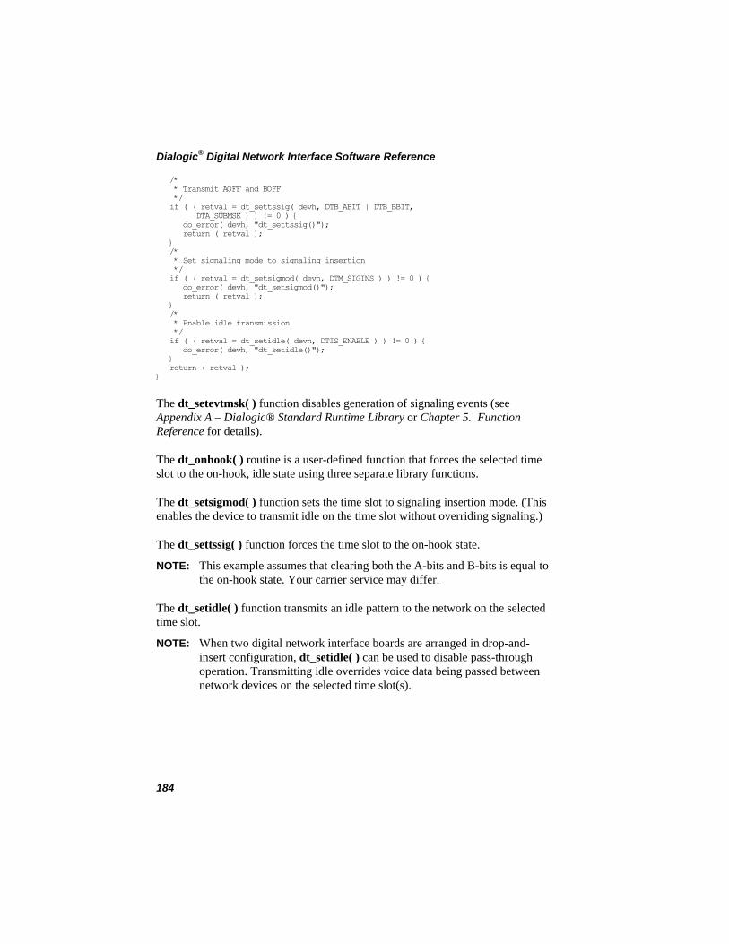
Dialogic® Digital Network Interface Software Reference
/* * Transmit AOFF and BOFF */ if ( ( retval = dt_settssig( devh, DTB_ABIT | DTB_BBIT, DTA_SUBMSK ) ) != 0 ) { do_error( devh, "dt_settssig()"); return ( retval ); } /* * Set signaling mode to signaling insertion */ if ( ( retval = dt_setsigmod( devh, DTM_SIGINS ) ) != 0 ) { do_error( devh, "dt_setsigmod()"); return ( retval ); } /* * Enable idle transmission */ if ( ( retval = dt_setidle( devh, DTIS_ENABLE ) ) != 0 ) { do_error( devh, "dt_setidle()"); } return ( retval ); }
The dt_setevtmsk( ) function disables generation of signaling events (see Appendix A – Dialogic® Standard Runtime Library or Chapter 5. Function Reference for details).
The dt_onhook( ) routine is a user-defined function that forces the selected time slot to the on-hook, idle state using three separate library functions.
The dt_setsigmod( ) function sets the time slot to signaling insertion mode. (This enables the device to transmit idle on the time slot without overriding signaling.)
The dt_settssig( ) function forces the time slot to the on-hook state.
NOTE: This example assumes that clearing both the A-bits and B-bits is equal to the on-hook state. Your carrier service may differ.
The dt_setidle( ) function transmits an idle pattern to the network on the selected time slot.
NOTE: When two digital network interface boards are arranged in drop-and-insert configuration, dt_setidle( ) can be used to disable pass-through operation. Transmitting idle overrides voice data being passed between network devices on the selected time slot(s).
184
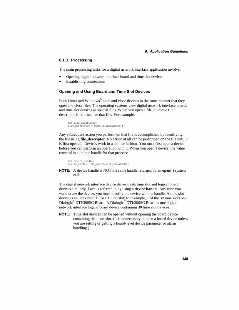
6. Application Guidelines
6.1.3. Processing
The main processing tasks for a digital network interface application involve:
• Opening digital network interface board and time slot devices • Establishing connections
Opening and Using Board and Time Slot Devices
Both Linux and Windows® open and close devices in the same manner that they open and close files. The operating systems view digital network interface boards and time slot devices as special files. When you open a file, a unique file descriptor is returned for that file. For example:
int file_descriptor; file_descriptor = open(filename,mode);
Any subsequent action you perform on that file is accomplished by identifying the file using file_descriptor. No action at all can be performed on the file until it is first opened. Devices work in a similar fashion. You must first open a device before you can perform an operation with it. When you open a device, the value returned is a unique handle for that process:
int device_handle; device_handle = dt_open(device_name,mode);
NOTE: A device handle is NOT the same handle returned by an open( ) system call.
The digital network interface device driver treats time slot and logical board devices similarly. Each is referred to by using a device handle. Any time you want to use the device, you must identify the device with its handle. A time slot device is an individual T1 or E1 time slot; for example, 1 of the 30 time slots on a Dialogic® DTI/300SC Board. A Dialogic® DTI/300SC Board is one digital network interface logical board device containing 30 time slot devices.
NOTE: Time slot devices can be opened without opening the board device containing that time slot. (It is unnecessary to open a board device unless you are setting or getting a board-level device parameter or alarm handling.)
185
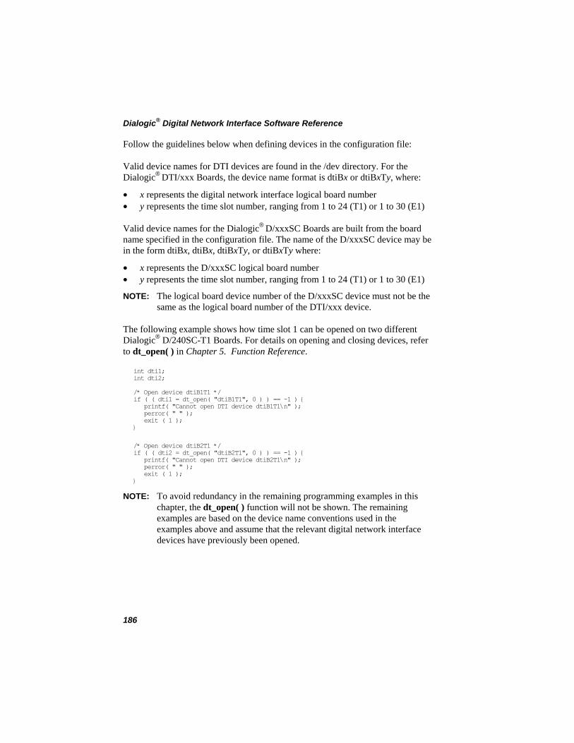
Dialogic® Digital Network Interface Software Reference
Follow the guidelines below when defining devices in the configuration file:
Valid device names for DTI devices are found in the /dev directory. For the Dialogic® DTI/xxx Boards, the device name format is dtiBx or dtiBxTTy, where:
• x represents the digital network interface logical board number • y represents the time slot number, ranging from 1 to 24 (T1) or 1 to 30 (E1)
Valid device names for the Dialogic® D/xxxSC Boards are built from the board name specified in the configuration file. The name of the D/xxxSC device may be in the form dtiBx, dtiBx, dtiBxTTy, or dtiBxTyT where:
• x represents the D/xxxSC logical board number • y represents the time slot number, ranging from 1 to 24 (T1) or 1 to 30 (E1)
NOTE: The logical board device number of the D/xxxSC device must not be the same as the logical board number of the DTI/xxx device.
The following example shows how time slot 1 can be opened on two different Dialogic® D/240SC-T1 Boards. For details on opening and closing devices, refer to dt_open( ) in Chapter 5. Function Reference.
int dti1; int dti2; /* Open device dtiB1T1 */ if ( ( dti1 = dt_open( "dtiB1T1", 0 ) ) == -1 ) { printf( "Cannot open DTI device dtiB1T1\n" ); perror( " " ); exit ( 1 ); }
/* Open device dtiB2T1 */ if ( ( dti2 = dt_open( "dtiB2T1", 0 ) ) == -1 ) { printf( "Cannot open DTI device dtiB2T1\n" ); perror( " " ); exit ( 1 ); }
NOTE: To avoid redundancy in the remaining programming examples in this chapter, the dt_open( ) function will not be shown. The remaining examples are based on the device name conventions used in the examples above and assume that the relevant digital network interface devices have previously been opened.
186
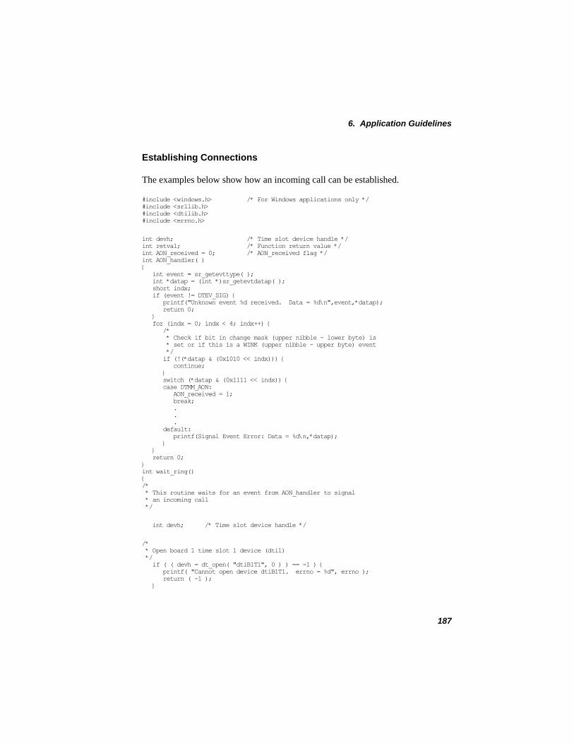
6. Application Guidelines
Establishing Connections
The examples below show how an incoming call can be established.
#include <windows.h> /* For Windows applications only */ #include <srllib.h> #include <dtilib.h> #include <errno.h>
int devh; /* Time slot device handle */ int retval; /* Function return value */ int AON_received = 0; /* AON_received flag */ int AON_handler( ) { int event = sr_getevttype( ); int *datap = (int *)sr_getevtdatap( ); short indx; if (event != DTEV_SIG) { printf("Unknown event %d received. Data = %d\n",event,*datap); return 0; } for (indx = 0; indx < 4; indx++) { /* * Check if bit in change mask (upper nibble - lower byte) is * set or if this is a WINK (upper nibble - upper byte) event */ if (!(*datap & (0x1010 << indx))) { continue; } switch (*datap & (0x1111 << indx)) { case DTMM_AON: AON_received = 1; break; . . . default: printf(Signal Event Error: Data = %d\n,*datap); } } return 0; } int wait_ring() { /* * This routine waits for an event from AON_handler to signal * an incoming call */
int devh; /* Time slot device handle */
/* * Open board 1 time slot 1 device (dti1) */ if ( ( devh = dt_open( "dtiB1T1", 0 ) ) == -1 ) { printf( "Cannot open device dtiB1T1. errno = %d", errno ); return ( -1 ); }
187
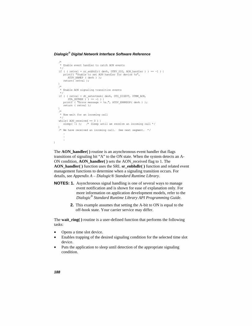
Dialogic® Digital Network Interface Software Reference
/* * Enable event handler to catch AON events */ if ( ( retval = sr_enbhdlr( devh, DTEV_SIG, AON_handler ) ) == -1 ) { printf( "Unable to set AON handler for device %s", ATDV_NAMEP ( devh ) ); return( retval ); } /* * Enable AON signaling transition events */ if ( ( retval = dt_setevtmsk( devh, DTG_SIGEVT, DTMM_AON, DTA_SETMSK ) ) == -1 ) { printf ( "Error message = %s.", ATDV_ERRMSGP( devh ) ); return ( retval ); } /* * Now wait for an incoming call */ while( AON_received == 0 ) { sleep( -1 ); /* Sleep until we receive an incoming call */ } /* We have received an incoming call. See next segment. */ . . . }
The AON_handler( ) routine is an asynchronous event handler that flags transitions of signaling bit “A” to the ON state. When the system detects an A-ON condition, AON_handler( ) sets the AON_received flag to 1. The AON_handler( ) function uses the SRL sr_enbhdlr( ) function and related event management functions to determine when a signaling transition occurs. For details, see Appendix A – Dialogic® Standard Runtime Library.
NOTES: 1. Asynchronous signal handling is one of several ways to manage event notification and is shown for ease of explanation only. For more information on application development models, refer to the Dialogic® Standard Runtime Library API Programming Guide.
2. This example assumes that setting the A-bit to ON is equal to the off-hook state. Your carrier service may differ.
The wait_ring( ) routine is a user-defined function that performs the following tasks:
• Opens a time slot device. • Enables trapping of the desired signaling condition for the selected time slot
device. • Puts the application to sleep until detection of the appropriate signaling
condition.
188
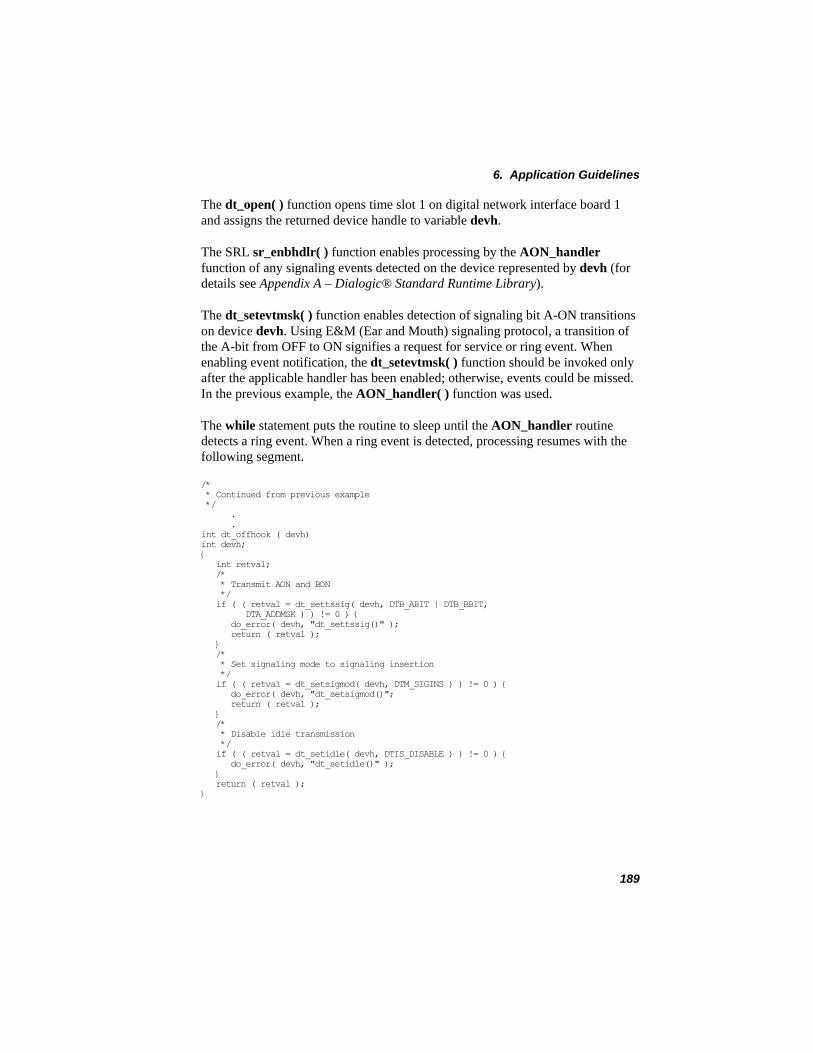
6. Application Guidelines
The dt_open( ) function opens time slot 1 on digital network interface board 1 and assigns the returned device handle to variable devh.
The SRL sr_enbhdlr( ) function enables processing by the AON_handler function of any signaling events detected on the device represented by devh (for details see Appendix A – Dialogic® Standard Runtime Library).
The dt_setevtmsk( ) function enables detection of signaling bit A-ON transitions on device devh. Using E&M (Ear and Mouth) signaling protocol, a transition of the A-bit from OFF to ON signifies a request for service or ring event. When enabling event notification, the dt_setevtmsk( ) function should be invoked only after the applicable handler has been enabled; otherwise, events could be missed. In the previous example, the AON_handler( ) function was used.
The while statement puts the routine to sleep until the AON_handler routine detects a ring event. When a ring event is detected, processing resumes with the following segment.
/* * Continued from previous example */ . . int dt_offhook ( devh) int devh; { int retval; /* * Transmit AON and BON */ if ( ( retval = dt_settssig( devh, DTB_ABIT | DTB_BBIT, DTA_ADDMSK ) ) != 0 ) { do_error( devh, "dt_settssig()" ); return ( retval ); } /* * Set signaling mode to signaling insertion */ if ( ( retval = dt_setsigmod( devh, DTM_SIGINS ) ) != 0 ) { do_error( devh, "dt_setsigmod()"; return ( retval ); } /* * Disable idle transmission */ if ( ( retval = dt_setidle( devh, DTIS_DISABLE ) ) != 0 ) { do_error( devh, "dt_setidle()" ); } return ( retval ); }
189
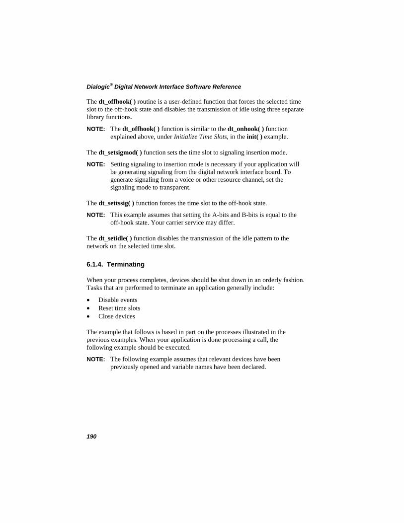
Dialogic® Digital Network Interface Software Reference
The dt_offhook( ) routine is a user-defined function that forces the selected time slot to the off-hook state and disables the transmission of idle using three separate library functions.
NOTE: The dt_offhook( ) function is similar to the dt_onhook( ) function explained above, under Initialize Time Slots, in the init( ) example.
The dt_setsigmod( ) function sets the time slot to signaling insertion mode.
NOTE: Setting signaling to insertion mode is necessary if your application will be generating signaling from the digital network interface board. To generate signaling from a voice or other resource channel, set the signaling mode to transparent.
The dt_settssig( ) function forces the time slot to the off-hook state.
NOTE: This example assumes that setting the A-bits and B-bits is equal to the off-hook state. Your carrier service may differ.
The dt_setidle( ) function disables the transmission of the idle pattern to the network on the selected time slot.
6.1.4. Terminating
When your process completes, devices should be shut down in an orderly fashion. Tasks that are performed to terminate an application generally include:
• Disable events • Reset time slots • Close devices
The example that follows is based in part on the processes illustrated in the previous examples. When your application is done processing a call, the following example should be executed.
NOTE: The following example assumes that relevant devices have been previously opened and variable names have been declared.
190
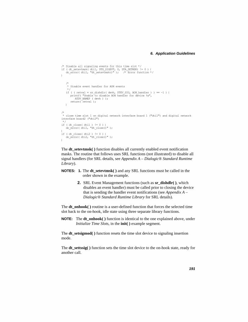
6. Application Guidelines
/* Disable all signaling events for this time slot */ if ( dt_setevtmsk( dti1, DTG_SIGEVT, 0, DTA_SETMSK) != 0 ) { do_error( dti1, "dt_setevtmsk()" ); /* Error function */ }
/* * Disable event handler for AON events */ if ( ( retval = sr_dishdlr( devh, DTEV_SIG, AON_handler ) ) == -1 ) { printf( "Unable to disable AON handler for device %s", ATDV_NAMEP ( devh ) ); return( retval ); }
/* * close time slot 1 on digital network interface board 1 ("dti1") and digital network interface board2 ("dti2") */ if ( dt_close( dti1 ) != 0 ) { do_error( dti1, "dt_close()" ); } if ( dt_close( dti2 ) != 0 ) { do_error( dti2, "dt_close()" ); }
The dt_setevtmsk( ) function disables all currently enabled event notification masks. The routine that follows uses SRL functions (not illustrated) to disable all signal handlers (for SRL details, see Appendix A – Dialogic® Standard Runtime Library).
NOTES: 1. The dt_setevtmsk( ) and any SRL functions must be called in the order shown in the example.
2. SRL Event Management functions (such as sr_dishdlr( ), which disables an event handler) must be called prior to closing the device that is sending the handler event notifications (see Appendix A – Dialogic® Standard Runtime Library for SRL details).
The dt_onhook( ) routine is a user-defined function that forces the selected time slot back to the on-hook, idle state using three separate library functions.
NOTE: The dt_onhook( ) function is identical to the one explained above, under Initialize Time Slots, in the init( ) example segment.
The dt_setsigmod( ) function resets the time slot device to signaling insertion mode.
The dt_settssig( ) function sets the time slot device to the on-hook state, ready for another call.
191
Dialogic® Digital Network Interface Software Reference
The dt_setidle( ) function transmits idle on the selected time slot. When two digital network interface boards are arranged in drop-and-insert configuration, dt_setidle( ) can be used to disable pass-through operation. Transmitting idle overrides voice data being passed between network devices on the selected time slot(s).
The dt_close( ) function closes the time slot device.
6.1.5. Compiling and Linking
To compile and link your application, follow the syntax instructions for your version of the C Development Package.
NOTE: Make sure when compiling or linking that the SRL library name is specified last. If your application includes Dialogic® Digital Network Interface and Voice Library functions, for instance, use either of the following two library orders on the command line:
-l dti -l dxxx -l srl
or
-l dxxx -l dti -l srl
6.1.6. Aborting
If you abort a digital network interface application by pressing the interrupt key, the system will terminate the current process but may leave devices in an unknown state. The next time you run your application, therefore, you may encounter errors.
To avoid errors of this type, your application should include an event handler that traps the interrupt key and performs the actions discussed under Section 6.1.4. Terminating.
6.2. Adding Advanced Features
When designing an application, you must test for digital network interface alarm, signaling, and other unsolicited or asynchronous events by constructing one or more event handlers. An event handler is an application-defined function that is called by the Dialogic® Standard Runtime Library (SRL).
192
6. Application Guidelines
NOTE: Event handling operations vary with the mode type (i.e., callback, polled, synchronous, etc.) used by your application. For more information on application development models, refer to the Dialogic® Standard Runtime Library API Programming Guide.
Warning
To avoid re-entrance problems, construction of an event handler must follow the same rules as a signal handler. Consult your system
administrator or documentation for detailed information.
Calls to the appropriate event handler are managed by the SRL. Within a digital network interface application, event notification may be enabled, disabled, held, and released by a combination of SRL and Digital Network Interface Library functions. For more information, refer to Appendix A – Dialogic® Standard Runtime Library.
193

Dialogic® Digital Network Interface Software Reference
194
7. Dialogic® Digital Network Interface API for Dialogic® DM3 Boards
This chapter describes the Dialogic® Digital Network Interface API support on Dialogic® DM3 Boards and notes any differences in the way the API is used on Dialogic® Springware Boards versus Dialogic® DM3 Boards.
7.1. Digital Network Interface API Function Restrictions
The Dialogic® Digital Network Interface Library contains functions for controlling the digital network interface (E1 or T1) to the Public Switched Telephone Network (PSTN). The Digital Network Interface Library includes functions for alarm handling, diagnostics, resource management, SCbus routing and others.
On Dialogic® DM3 Boards, most Digital Network Interface functions are not supported since the same functionality can be achieved using the Dialogic®
Global Call API. However, the resource management and TDM bus routing functions are supported as shown in Table 8. Dialogic® DM3 Boards can use the DTI API for Layer 1 alarms (see Section 7.2. Detecting Layer 1 Alarms). All other DTI functions are not supported.
NOTE: If you execute a function that is not supported on Dialogic® DM3 Boards, it produces an EDT_NOTIMP (“not implemented”) error.
195
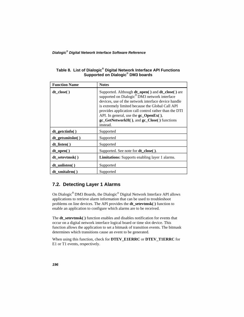
Dialogic® Digital Network Interface Software Reference
Table 8. List of Dialogic® Digital Network Interface API Functions Supported on Dialogic® DM3 boards
Function Name Notes
dt_close( ) Supported. Although dt_open( ) and dt_close( ) are supported on Dialogic® DM3 network interface devices, use of the network interface device handle is extremely limited because the Global Call API provides application call control rather than the DTI API. In general, use the gc_OpenEx( ), gc_GetNetworkH( ), and gc_Close( ) functions instead.
dt_getctinfo( ) Supported dt_getxmitslot( ) Supported dt_listen( ) Supported dt_open( ) Supported. See note for dt_close( ). dt_setevtmsk( ) Limitations: Supports enabling layer 1 alarms.
dt_unlisten( ) Supported dt_xmitalrm( ) Supported
7.2. Detecting Layer 1 Alarms
On Dialogic® DM3 Boards, the Dialogic® Digital Network Interface API allows applications to retrieve alarm information that can be used to troubleshoot problems on line devices. The API provides the dt_setevtmsk( ) function to enable an application to configure which alarms are to be received.
The dt_setevtmsk( ) function enables and disables notification for events that occur on a digital network interface logical board or time slot device. This function allows the application to set a bitmask of transition events. The bitmask determines which transitions cause an event to be generated.
When using this function, check for DTEV_E1ERRC or DTEV_T1ERRC for E1 or T1 events, respectively.
196
7. Dialogic® Digital Network Interface API for Dialogic® DM3 Boards
NOTE: Since dt_getevtmsk( ) is not supported, the application must keep track of the bitmask of events previously set with the dt_setevtmsk( ) function.
197

Dialogic® Digital Network Interface Software Reference
198
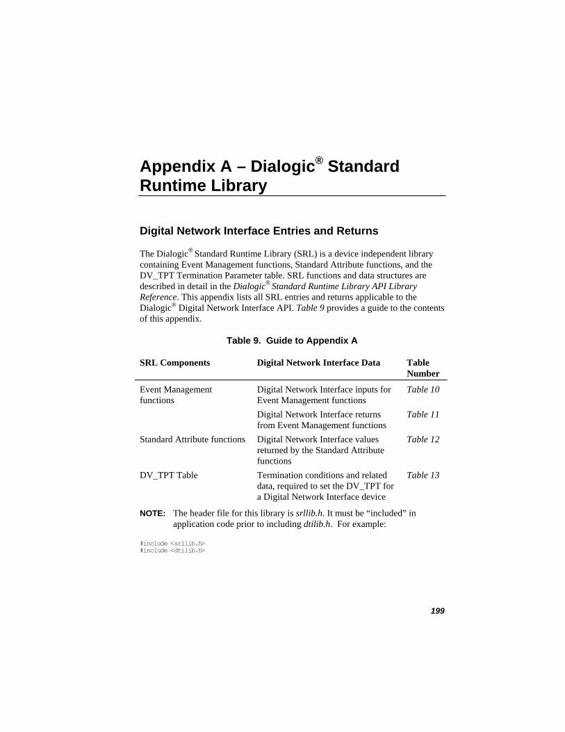
Appendix A – Dialogic® Standard Runtime Library
Digital Network Interface Entries and Returns
The Dialogic® Standard Runtime Library (SRL) is a device independent library containing Event Management functions, Standard Attribute functions, and the DV_TPT Termination Parameter table. SRL functions and data structures are described in detail in the Dialogic® Standard Runtime Library API Library Reference. This appendix lists all SRL entries and returns applicable to the Dialogic® Digital Network Interface API. Table 9 provides a guide to the contents of this appendix.
Table 9. Guide to Appendix A
SRL Components Digital Network Interface Data Table Number
Table 10Event Management functions
Digital Network Interface inputs for Event Management functions
Table 11 Digital Network Interface returns from Event Management functions
Table 12Standard Attribute functions Digital Network Interface values returned by the Standard Attribute functions
Table 13DV_TPT Table Termination conditions and related data, required to set the DV_TPT for a Digital Network Interface device
NOTE: The header file for this library is srllib.h. It must be “included” in application code prior to including dtilib.h. For example:
#include <srllib.h> #include <dtilib.h>
199
Dialogic® Digital Network Interface Software Reference
Event Management Functions
The Event Management functions enable processing of unsolicited and asynchronous termination events returned by library functions. For the Dialogic® Digital Network Interface API, these functions include:
dt_rundiag( ) dt_setevtmsk( )dt_tstcom( )dt_tstdat( )dt_xmitwink( )
The Event Management functions applicable to the Digital Network Interface API are listed in the following tables. Table 10 shows digital network interface-specific inputs and Table 11 shows valid digital network interface returns.
200
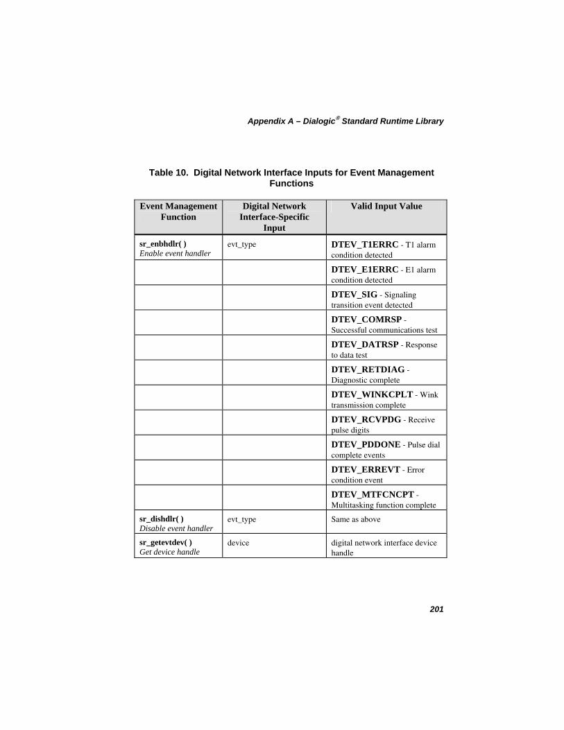
Appendix A – Dialogic® Standard Runtime Library
Table 10. Digital Network Interface Inputs for Event Management Functions
Event Management Function
Digital Network Interface-Specific
Input
Valid Input Value
sr_enbhdlr( ) Enable event handler
evt_type DTEV_T1ERRC - T1 alarm condition detected DTEV_E1ERRC - E1 alarm condition detected
DTEV_SIG - Signaling transition event detected
DTEV_COMRSP - Successful communications test
DTEV_DATRSP - Response to data test
DTEV_RETDIAG - Diagnostic complete
DTEV_WINKCPLT - Wink transmission complete
DTEV_RCVPDG - Receive pulse digits
DTEV_PDDONE - Pulse dial complete events
DTEV_ERREVT - Error condition event
DTEV_MTFCNCPT - Multitasking function complete
sr_dishdlr( ) Disable event handler
evt_type Same as above
sr_getevtdev( ) Get device handle
device digital network interface device handle
201
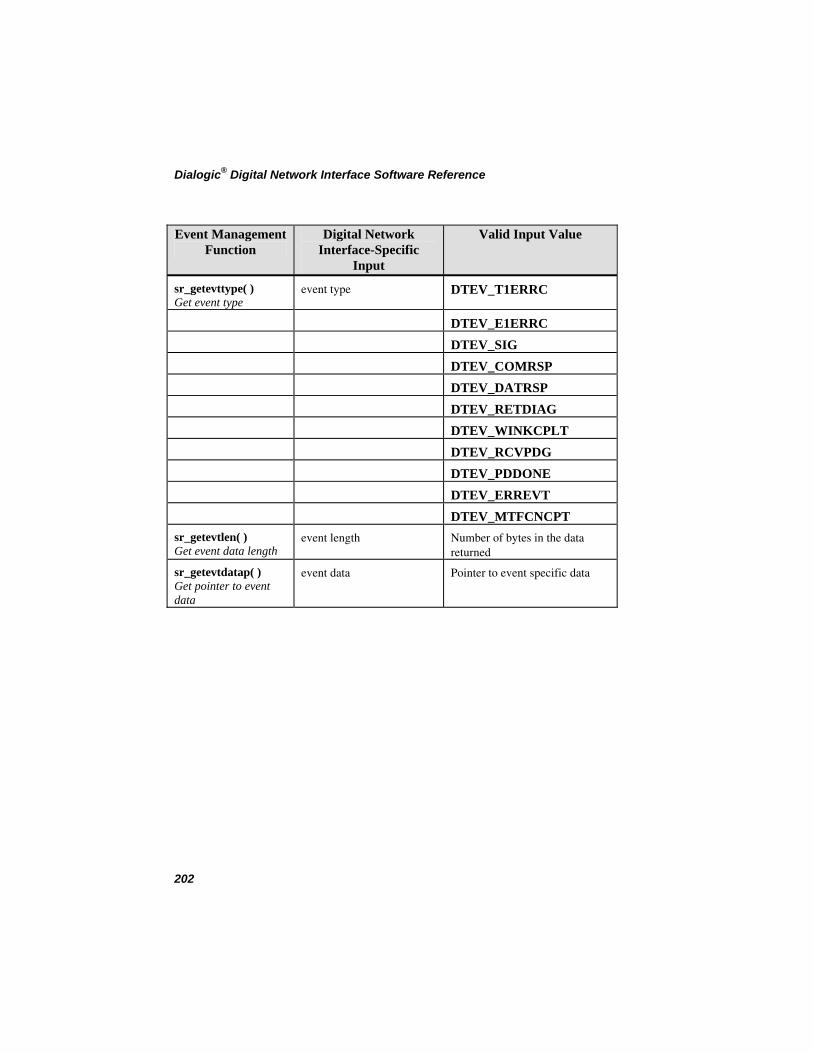
Dialogic® Digital Network Interface Software Reference
Event Management Function
Digital Network Valid Input Value Interface-Specific
Input
sr_getevttype( ) Get event type
event type DTEV_T1ERRC
DTEV_E1ERRC DTEV_SIG DTEV_COMRSP DTEV_DATRSP DTEV_RETDIAG DTEV_WINKCPLT DTEV_RCVPDG DTEV_PDDONE DTEV_ERREVT DTEV_MTFCNCPT
sr_getevtlen( ) Get event data length
event length Number of bytes in the data returned
sr_getevtdatap( ) Get pointer to event data
event data Pointer to event specific data
202
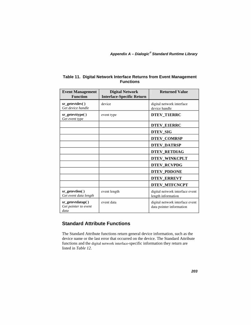
Appendix A – Dialogic® Standard Runtime Library
Table 11. Digital Network Interface Returns from Event Management Functions
Event Management Function
Digital Network Interface-Specific Return
Returned Value
sr_getevtdev( ) Get device handle
device digital network interface device handle
sr_getevttype( ) Get event type
event type DTEV_T1ERRC
DTEV_E1ERRC DTEV_SIG DTEV_COMRSP DTEV_DATRSP DTEV_RETDIAG DTEV_WINKCPLT DTEV_RCVPDG DTEV_PDDONE DTEV_ERREVT DTEV_MTFCNCPT
sr_getevtlen( ) Get event data length
event length digital network interface event length information
sr_getevtdatap( ) Get pointer to event data
event data digital network interface event data pointer information
Standard Attribute Functions
The Standard Attribute functions return general device information, such as the device name or the last error that occurred on the device. The Standard Attribute functions and the digital network interface-specific information they return are listed in Table 12.
203
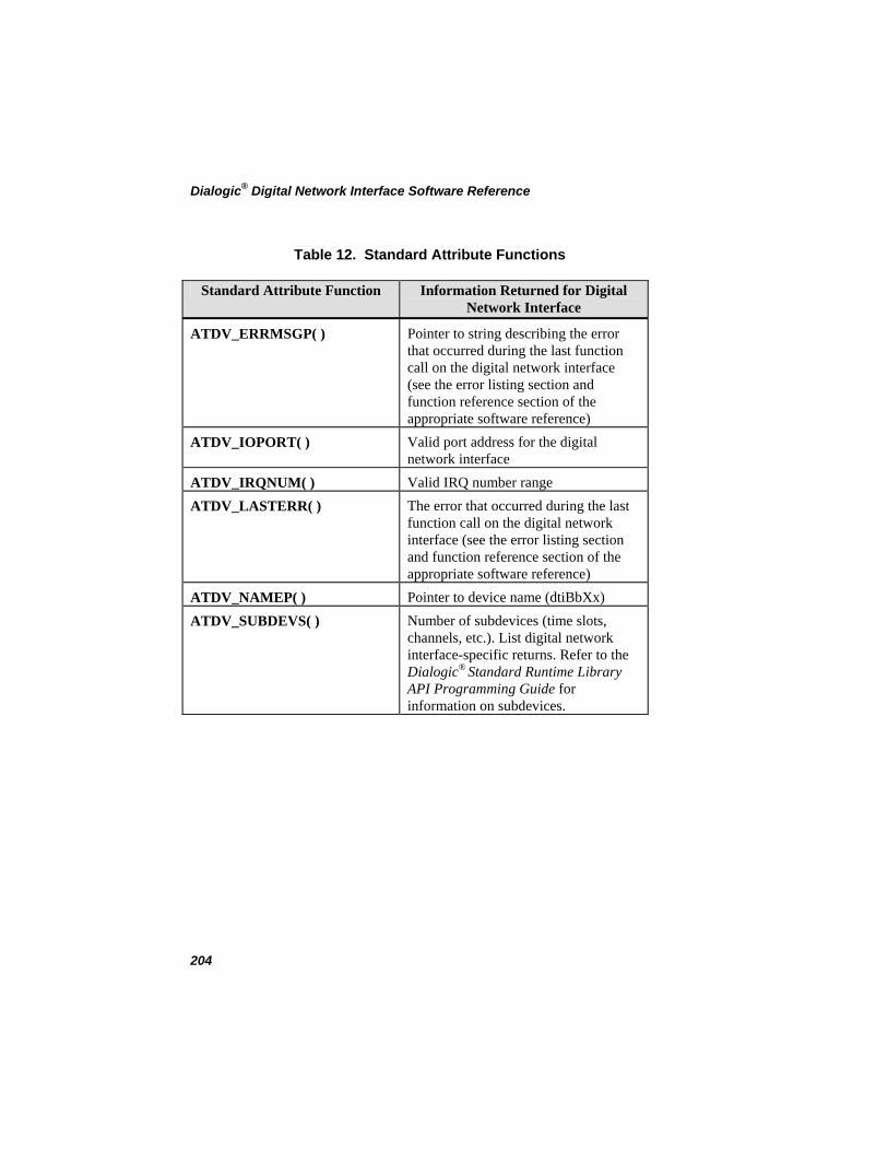
Dialogic® Digital Network Interface Software Reference
Table 12. Standard Attribute Functions
Standard Attribute Function Information Returned for Digital Network Interface
ATDV_ERRMSGP( ) Pointer to string describing the error that occurred during the last function call on the digital network interface (see the error listing section and function reference section of the appropriate software reference)
ATDV_IOPORT( ) Valid port address for the digital network interface
ATDV_IRQNUM( ) Valid IRQ number range ATDV_LASTERR( ) The error that occurred during the last
function call on the digital network interface (see the error listing section and function reference section of the appropriate software reference)
ATDV_NAMEP( ) Pointer to device name (dtiBbXx) ATDV_SUBDEVS( ) Number of subdevices (time slots,
channels, etc.). List digital network interface-specific returns. Refer to the Dialogic® Standard Runtime Library API Programming Guide for information on subdevices.
204
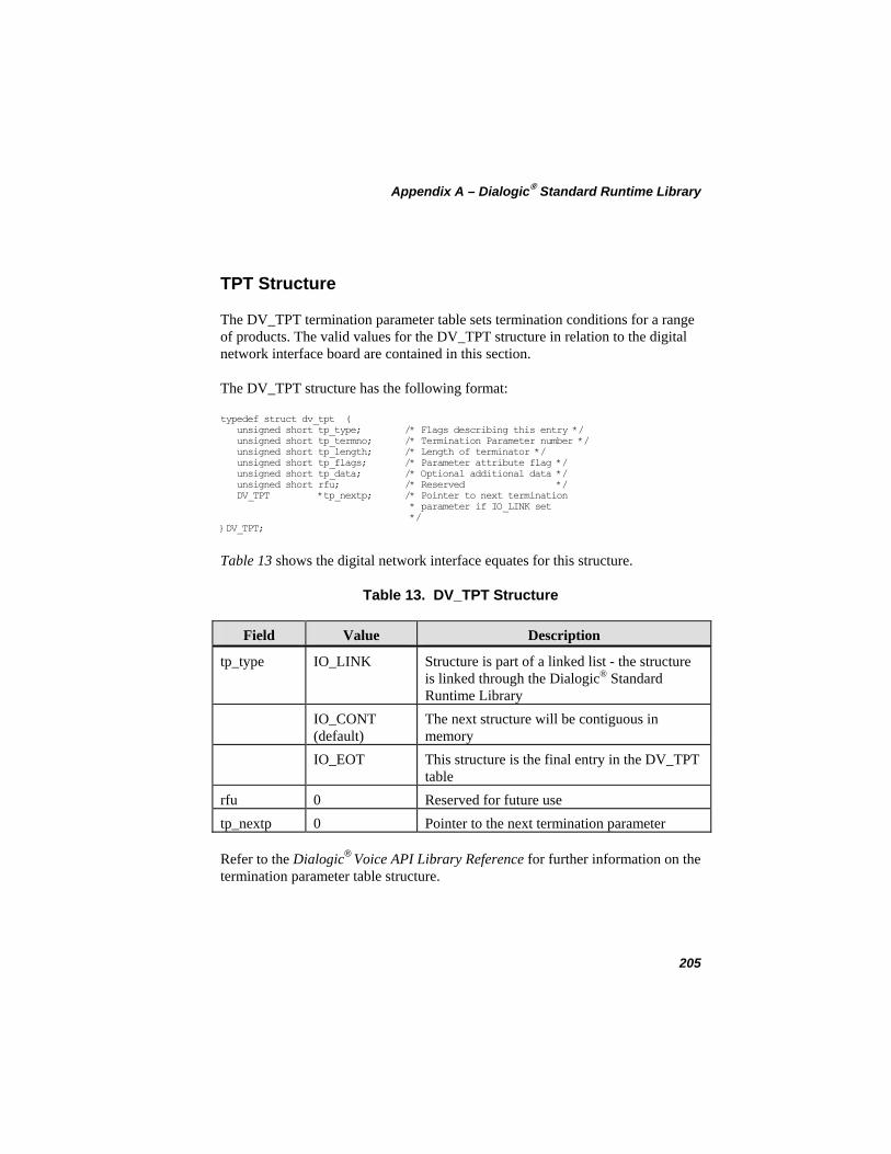
Appendix A – Dialogic® Standard Runtime Library
TPT Structure
The DV_TPT termination parameter table sets termination conditions for a range of products. The valid values for the DV_TPT structure in relation to the digital network interface board are contained in this section.
The DV_TPT structure has the following format:
typedef struct dv_tpt ( unsigned short tp_type; /* Flags describing this entry */ unsigned short tp_termno; /* Termination Parameter number */ unsigned short tp_length; /* Length of terminator */ unsigned short tp_flags; /* Parameter attribute flag */ unsigned short tp_data; /* Optional additional data */ unsigned short rfu; /* Reserved */ DV_TPT *tp_nextp; /* Pointer to next termination * parameter if IO_LINK set */ }DV_TPT;
Table 13 shows the digital network interface equates for this structure.
Table 13. DV_TPT Structure
Field Value Description
tp_type IO_LINK Structure is part of a linked list - the structure is linked through the Dialogic® Standard Runtime Library
IO_CONT (default)
The next structure will be contiguous in memory
IO_EOT This structure is the final entry in the DV_TPT table
rfu 0 Reserved for future use tp_nextp 0 Pointer to the next termination parameter
Refer to the Dialogic® Voice API Library Reference for further information on the termination parameter table structure.
205

Dialogic® Digital Network Interface Software Reference
206
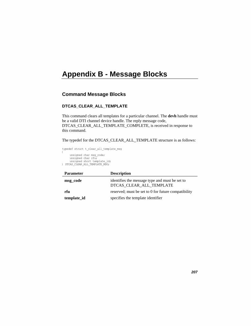
Appendix B - Message Blocks
Command Message Blocks
DTCAS_CLEAR_ALL_TEMPLATE
This command clears all templates for a particular channel. The devh handle must be a valid DTI channel device handle. The reply message code, DTCAS_CLEAR_ALL_TEMPLATE_COMPLETE, is received in response to this command.
The typedef for the DTCAS_CLEAR_ALL_TEMPLATE structure is as follows:
typedef struct t_clear_all_template_msg { unsigned char msg_code; unsigned char rfu; unsigned short template_id; } DTCAS_CLEAR_ALL_TEMPLATE_MSG;
Parameter Description
msg_code identifies the message type and must be set to DTCAS_CLEAR_ALL_TEMPLATE
rfu reserved; must be set to 0 for future compatibility template_id specifies the template identifier
207
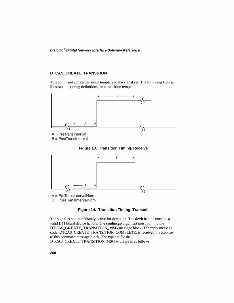
Dialogic® Digital Network Interface Software Reference
DTCAS_CREATE_TRANSITION
This command adds a transition template to the signal set. The following figures illustrate the timing definitions for a transition template.
A
B
A = PreTransIntervalB = PostTransInterval
Figure 13. Transition Timing, Receive
A
B
A = PreTransIntervalNomB = PostTransIntervalNom
Figure 14. Transition Timing, Transmit
The signal is not immediately active for detection. The devh handle must be a valid DTI board device handle. The cmdmsgp argument must point to the DTCAS_CREATE_TRANSITION_MSG message block. The reply message code, DTCAS_CREATE_TRANSITION_COMPLETE, is received in response to this command message block. The typedef for the DTCAS_CREATE_TRANSITION_MSG structure is as follows:
208
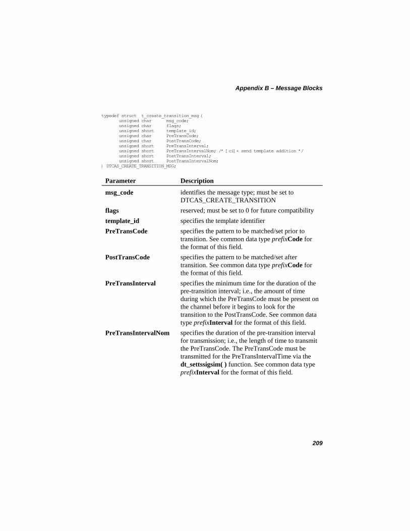
Appendix B – Message Blocks
typedef struct t_create_transition_msg { unsigned char msg_code; unsigned char flags; unsigned short template_id; unsigned char PreTransCode; unsigned char PostTransCode; unsigned short PreTransInterval; unsigned short PreTransIntervalNom; /* [ci]+ send template addition */ unsigned short PostTransInterval; unsigned short PostTransIntervalNom; } DTCAS_CREATE_TRANSITION_MSG;
Parameter Description
msg_code identifies the message type; must be set to DTCAS_CREATE_TRANSITION
flags reserved; must be set to 0 for future compatibility template_id specifies the template identifier PreTransCode specifies the pattern to be matched/set prior to
transition. See common data type prefixCode for the format of this field.
PostTransCode specifies the pattern to be matched/set after transition. See common data type prefixCode for the format of this field.
PreTransInterval specifies the minimum time for the duration of the pre-transition interval; i.e., the amount of time during which the PreTransCode must be present on the channel before it begins to look for the transition to the PostTransCode. See common data type prefixInterval for the format of this field.
PreTransIntervalNom specifies the duration of the pre-transition interval for transmission; i.e., the length of time to transmit the PreTransCode. The PreTransCode must be transmitted for the PreTransIntervalTime via the dt_settssigsim( ) function. See common data type prefixInterval for the format of this field.
209
Dialogic® Digital Network Interface Software Reference
Parameter Description
PostTransInterval specifies the minimum time for the duration of the post-transition interval; i.e., the amount of time during which the PostTransCode must be present on the channel after the PreTransCode has been detected for the PreTransInterval time. See common data type prefixInterval for the format of this field.
PostTransIntervalNom specifies the duration of the post-transition interval for transmission; i.e., the length of time to transmit the PostTransCode. See common data type prefixInterval for the format of this field.
210
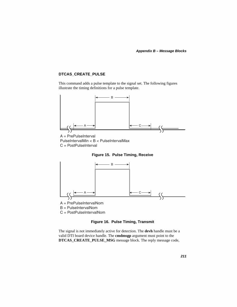
Appendix B – Message Blocks
DTCAS_CREATE_PULSE
This command adds a pulse template to the signal set. The following figures illustrate the timing definitions for a pulse template.
A
B
C
A = PrePulseIntervalPulseIntervalMin < B < PulseIntervalMaxC = PostPulseInterval
Figure 15. Pulse Timing, Receive
A
B
C
A = PrePulseIntervalNomB = PulseIntervalNomC = PostPulseIntervalNom
Figure 16. Pulse Timing, Transmit
The signal is not immediately active for detection. The devh handle must be a valid DTI board device handle. The cmdmsgp argument must point to the DTCAS_CREATE_PULSE_MSG message block. The reply message code,
211
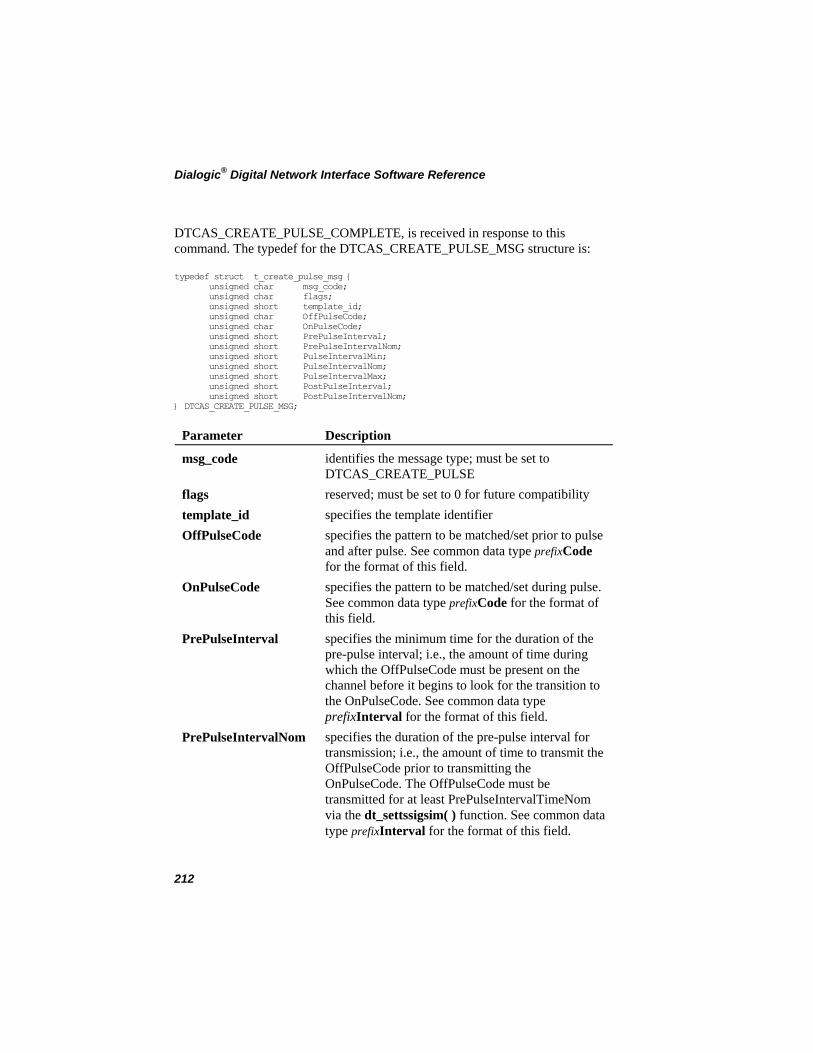
Dialogic® Digital Network Interface Software Reference
DTCAS_CREATE_PULSE_COMPLETE, is received in response to this command. The typedef for the DTCAS_CREATE_PULSE_MSG structure is:
typedef struct t_create_pulse_msg { unsigned char msg_code; unsigned char flags; unsigned short template_id; unsigned char OffPulseCode; unsigned char OnPulseCode; unsigned short PrePulseInterval; unsigned short PrePulseIntervalNom; unsigned short PulseIntervalMin; unsigned short PulseIntervalNom; unsigned short PulseIntervalMax; unsigned short PostPulseInterval; unsigned short PostPulseIntervalNom; } DTCAS_CREATE_PULSE_MSG;
Parameter Description
msg_code identifies the message type; must be set to DTCAS_CREATE_PULSE
flags reserved; must be set to 0 for future compatibility template_id specifies the template identifier OffPulseCode specifies the pattern to be matched/set prior to pulse
and after pulse. See common data type prefixCode for the format of this field.
OnPulseCode specifies the pattern to be matched/set during pulse. See common data type prefixCode for the format of this field.
PrePulseInterval specifies the minimum time for the duration of the pre-pulse interval; i.e., the amount of time during which the OffPulseCode must be present on the channel before it begins to look for the transition to the OnPulseCode. See common data type prefixInterval for the format of this field.
PrePulseIntervalNom specifies the duration of the pre-pulse interval for transmission; i.e., the amount of time to transmit the OffPulseCode prior to transmitting the OnPulseCode. The OffPulseCode must be transmitted for at least PrePulseIntervalTimeNom via the dt_settssigsim( ) function. See common data type prefixInterval for the format of this field.
212
Appendix B – Message Blocks
Parameter Description
PulseIntervalMin specifies the minimum time for the duration of the pulse interval; i.e., the minimum amount of time during which the OnPulseCode must be present on the channel before it transitions to the OffPulseCode. See common data type prefixInterval for the format of this field.
PulseIntervalMax specifies the maximum time for the duration of the pulse interval; i.e., the maximum amount of time during which the OnPulseCode can be present on the channel before it transitions to the OffPulseCode. See common data type prefixInterval for the format of this field.
PulseIntervalNom specifies the desired time for the duration of the pulse interval; i.e., the amount of time to transmit the OnPulseCode prior to transmitting the OffPulseCode. See common data type prefixInterval for the format of this field.
PostPulseInterval specifies the minimum time for the duration of the end-of-pulse interval; i.e., the minimum amount of time during which the OffPulseCode must be present on the channel after OnPulseCode is detected for a minimum of PulseIntervalMin and a maximum of PulseIntervalMax. See common data type prefixInterval for the format of this field.
PostPulseIntervalNom specifies the duration of the end-of-pulse interval for transmission; i.e., the amount of time to transmit the OffPulseCode after transmitting the OnPulseCode for PulseIntervalTime. See common data type prefixInterval for the format of this field.
213
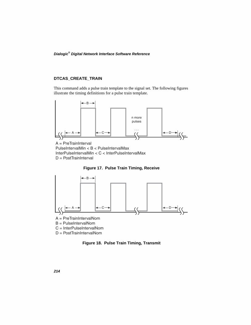
Dialogic® Digital Network Interface Software Reference
DTCAS_CREATE_TRAIN
This command adds a pulse train template to the signal set. The following figures illustrate the timing definitions for a pulse train template.
A
B
C
n morepulses
. . .D
A = PreTrainIntervalPulseIntervalMin < B < PulseIntervalMaxInterPulseIntervalMin < C < InterPulseIntervalMaxD = PostTrainInterval
Figure 17. Pulse Train Timing, Receive
A
B
C D
A = PreTrainIntervalNomB = PulseIntervalNomC = InterPulseIntervalNomD = PostTrainIntervalNom
Figure 18. Pulse Train Timing, Transmit
214
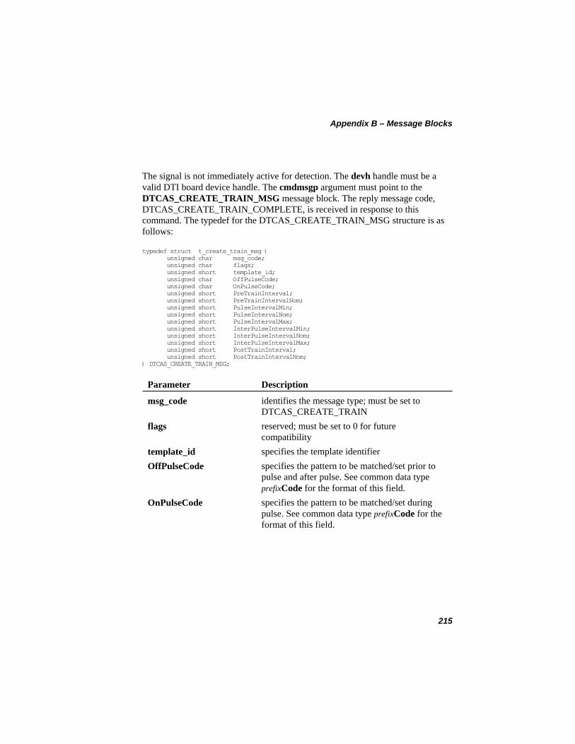
Appendix B – Message Blocks
The signal is not immediately active for detection. The devh handle must be a valid DTI board device handle. The cmdmsgp argument must point to the DTCAS_CREATE_TRAIN_MSG message block. The reply message code, DTCAS_CREATE_TRAIN_COMPLETE, is received in response to this command. The typedef for the DTCAS_CREATE_TRAIN_MSG structure is as follows:
typedef struct t_create_train_msg { unsigned char msg_code; unsigned char flags; unsigned short template_id; unsigned char OffPulseCode; unsigned char OnPulseCode; unsigned short PreTrainInterval; unsigned short PreTrainIntervalNom; unsigned short PulseIntervalMin; unsigned short PulseIntervalNom; unsigned short PulseIntervalMax; unsigned short InterPulseIntervalMin; unsigned short InterPulseIntervalNom; unsigned short InterPulseIntervalMax; unsigned short PostTrainInterval; unsigned short PostTrainIntervalNom; } DTCAS_CREATE_TRAIN_MSG;
Parameter Description
identifies the message type; must be set to DTCAS_CREATE_TRAIN
msg_code
flags reserved; must be set to 0 for future compatibility
template_id specifies the template identifier OffPulseCode specifies the pattern to be matched/set prior to
pulse and after pulse. See common data type prefixCode for the format of this field.
OnPulseCode specifies the pattern to be matched/set during pulse. See common data type prefixCode for the format of this field.
215
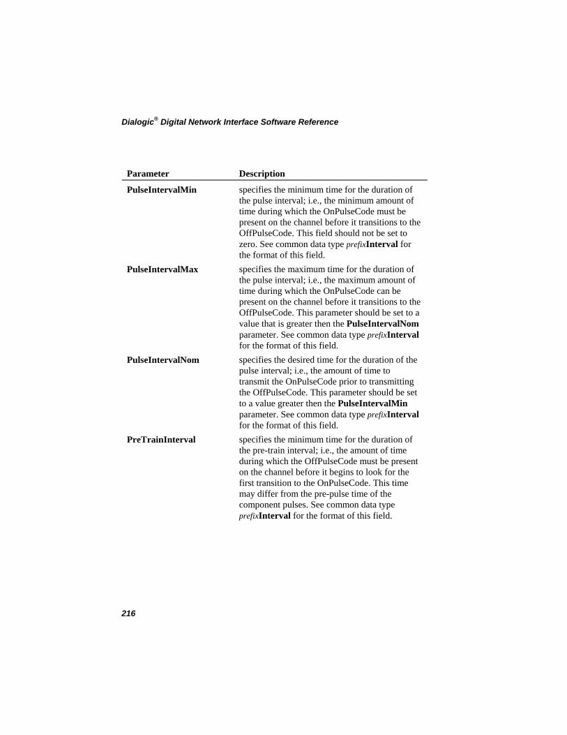
Dialogic® Digital Network Interface Software Reference
Parameter Description
PulseIntervalMin specifies the minimum time for the duration of the pulse interval; i.e., the minimum amount of time during which the OnPulseCode must be present on the channel before it transitions to the OffPulseCode. This field should not be set to zero. See common data type prefixInterval for the format of this field.
PulseIntervalMax specifies the maximum time for the duration of the pulse interval; i.e., the maximum amount of time during which the OnPulseCode can be present on the channel before it transitions to the OffPulseCode. This parameter should be set to a value that is greater then the PulseIntervalNom parameter. See common data type prefixInterval for the format of this field.
PulseIntervalNom specifies the desired time for the duration of the pulse interval; i.e., the amount of time to transmit the OnPulseCode prior to transmitting the OffPulseCode. This parameter should be set to a value greater then the PulseIntervalMin parameter. See common data type prefixInterval for the format of this field.
PreTrainInterval specifies the minimum time for the duration of the pre-train interval; i.e., the amount of time during which the OffPulseCode must be present on the channel before it begins to look for the first transition to the OnPulseCode. This time may differ from the pre-pulse time of the component pulses. See common data type prefixInterval for the format of this field.
216
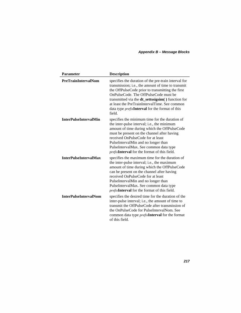
Appendix B – Message Blocks
Parameter Description
PreTrainIntervalNom specifies the duration of the pre-train interval for transmission; i.e., the amount of time to transmit the OffPulseCode prior to transmitting the first OnPulseCode. The OffPulseCode must be transmitted via the dt_settssigsim( ) function for at least the PreTrainIntervalTime. See common data type prefixInterval for the format of this field.
InterPulseIntervalMin specifies the minimum time for the duration of the inter-pulse interval; i.e., the minimum amount of time during which the OffPulseCode must be present on the channel after having received OnPulseCode for at least PulseIntervalMin and no longer than PulseIntervalMax. See common data type prefixInterval for the format of this field.
InterPulseIntervalMax specifies the maximum time for the duration of the inter-pulse interval; i.e., the maximum amount of time during which the OffPulseCode can be present on the channel after having received OnPulseCode for at least PulseIntervalMin and no longer than PulseIntervalMax. See common data type prefixInterval for the format of this field.
InterPulseIntervalNom specifies the desired time for the duration of the inter-pulse interval; i.e., the amount of time to transmit the OffPulseCode after transmission of the OnPulseCode for PulseIntervalNom. See common data type prefixInterval for the format of this field.
217
Dialogic® Digital Network Interface Software Reference
Parameter Description
PostTrainInterval specifies the minimum time for the duration of the end-of-train interval; i.e., the minimum amount of time during which the OffPulseCode must be present on the channel after the last OnPulseCode is detected for a minimum of PulseIntervalMin and a maximum of PulseIntervalMax. See common data type prefixInterval for the format of this field.
PostTrainIntervalNom specifies the minimum time for the duration of the end-of-train interval; i.e., the amount of time to transmit the OffPulseCode after transmitting the last OnPulseCode for PulseIntervalTime. See common data type prefixInterval for the format of this field.
218
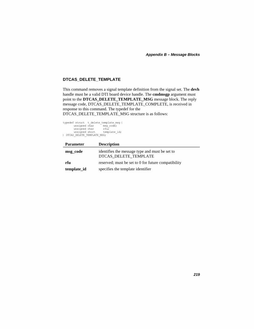
Appendix B – Message Blocks
DTCAS_DELETE_TEMPLATE
This command removes a signal template definition from the signal set. The devh handle must be a valid DTI board device handle. The cmdmsgp argument must point to the DTCAS_DELETE_TEMPLATE_MSG message block. The reply message code, DTCAS_DELETE_TEMPLATE_COMPLETE, is received in response to this command. The typedef for the DTCAS_DELETE_TEMPLATE_MSG structure is as follows:
typedef struct t_delete_template_msg { unsigned char msg_code; unsigned char rfu; unsigned short template_id; } DTCAS_DELETE_TEMPLATE_MSG;
Parameter Description
identifies the message type and must be set to DTCAS_DELETE_TEMPLATE
msg_code
rfu reserved; must be set to 0 for future compatibility template_id specifies the template identifier
219
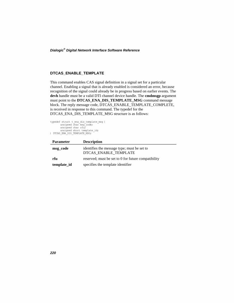
Dialogic® Digital Network Interface Software Reference
DTCAS_ENABLE_TEMPLATE
This command enables CAS signal definition in a signal set for a particular channel. Enabling a signal that is already enabled is considered an error, because recognition of the signal could already be in progress based on earlier events. The devh handle must be a valid DTI channel device handle. The cmdmsgp argument must point to the DTCAS_ENA_DIS_TEMPLATE_MSG command message block. The reply message code, DTCAS_ENABLE_TEMPLATE_COMPLETE, is received in response to this command. The typedef for the DTCAS_ENA_DIS_TEMPLATE_MSG structure is as follows:
typedef struct t_ena_dis_template_msg { unsigned char msg_code; unsigned char rfu; unsigned short template_id; } DTCAS_ENA_DIS_TEMPLATE_MSG;
Parameter Description
identifies the message type; must be set to DTCAS_ENABLE_TEMPLATE
msg_code
rfu reserved; must be set to 0 for future compatibility template_id specifies the template identifier
220
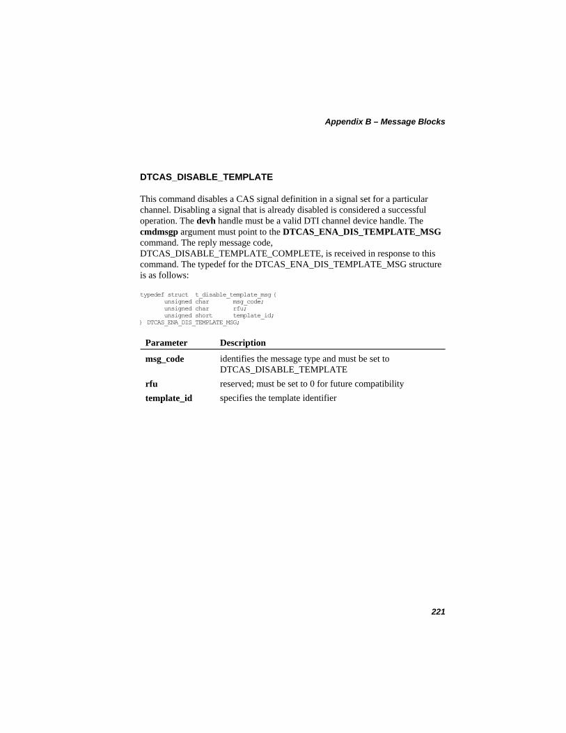
Appendix B – Message Blocks
DTCAS_DISABLE_TEMPLATE
This command disables a CAS signal definition in a signal set for a particular channel. Disabling a signal that is already disabled is considered a successful operation. The devh handle must be a valid DTI channel device handle. The cmdmsgp argument must point to the DTCAS_ENA_DIS_TEMPLATE_MSG command. The reply message code, DTCAS_DISABLE_TEMPLATE_COMPLETE, is received in response to this command. The typedef for the DTCAS_ENA_DIS_TEMPLATE_MSG structure is as follows:
typedef struct t_disable_template_msg { unsigned char msg_code; unsigned char rfu; unsigned short template_id; } DTCAS_ENA_DIS_TEMPLATE_MSG;
Parameter Description
identifies the message type and must be set to DTCAS_DISABLE_TEMPLATE
msg_code
rfu reserved; must be set to 0 for future compatibility template_id specifies the template identifier
221
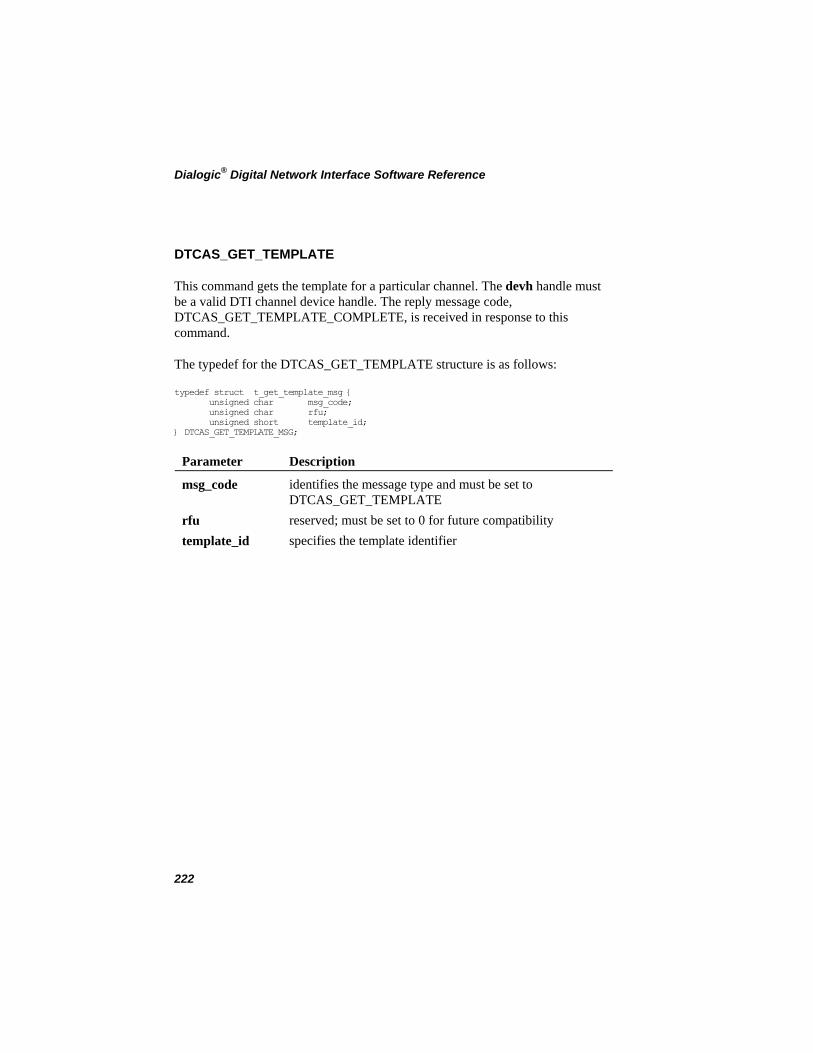
Dialogic® Digital Network Interface Software Reference
DTCAS_GET_TEMPLATE
This command gets the template for a particular channel. The devh handle must be a valid DTI channel device handle. The reply message code, DTCAS_GET_TEMPLATE_COMPLETE, is received in response to this command.
The typedef for the DTCAS_GET_TEMPLATE structure is as follows:
typedef struct t_get_template_msg { unsigned char msg_code; unsigned char rfu; unsigned short template_id; } DTCAS_GET_TEMPLATE_MSG;
Parameter Description
identifies the message type and must be set to DTCAS_GET_TEMPLATE
msg_code
rfu reserved; must be set to 0 for future compatibility template_id specifies the template identifier
222
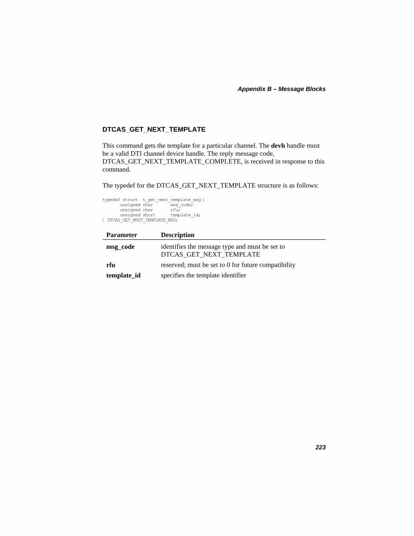
Appendix B – Message Blocks
DTCAS_GET_NEXT_TEMPLATE
This command gets the template for a particular channel. The devh handle must be a valid DTI channel device handle. The reply message code, DTCAS_GET_NEXT_TEMPLATE_COMPLETE, is received in response to this command.
The typedef for the DTCAS_GET_NEXT_TEMPLATE structure is as follows:
typedef struct t_get_next_template_msg { unsigned char msg_code; unsigned char rfu; unsigned short template_id; } DTCAS_GET_NEXT_TEMPLATE_MSG;
Parameter Description
identifies the message type and must be set to DTCAS_GET_NEXT_TEMPLATE
msg_code
rfu reserved; must be set to 0 for future compatibility template_id specifies the template identifier
223
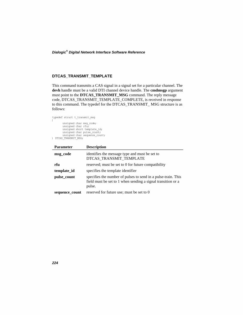
Dialogic® Digital Network Interface Software Reference
DTCAS_TRANSMIT_TEMPLATE
This command transmits a CAS signal in a signal set for a particular channel. The devh handle must be a valid DTI channel device handle. The cmdmsgp argument must point to the DTCAS_TRANSMIT_MSG command. The reply message code, DTCAS_TRANSMIT_TEMPLATE_COMPLETE, is received in response to this command. The typedef for the DTCAS_TRANSMIT_ MSG structure is as follows:
typedef struct t_transmit_msg { unsigned char msg_code; unsigned char rfu; unsigned short template_id; unsigned char pulse_count; unsigned char sequence_count; } DTCAS_TRANSMIT_MSG;
Parameter Description
identifies the message type and must be set to DTCAS_TRANSMIT_TEMPLATE
msg_code
rfu reserved; must be set to 0 for future compatibility template_id specifies the template identifier pulse_count specifies the number of pulses to send in a pulse-train. This
field must be set to 1 when sending a signal transition or a pulse.
sequence_count reserved for future use; must be set to 0
224
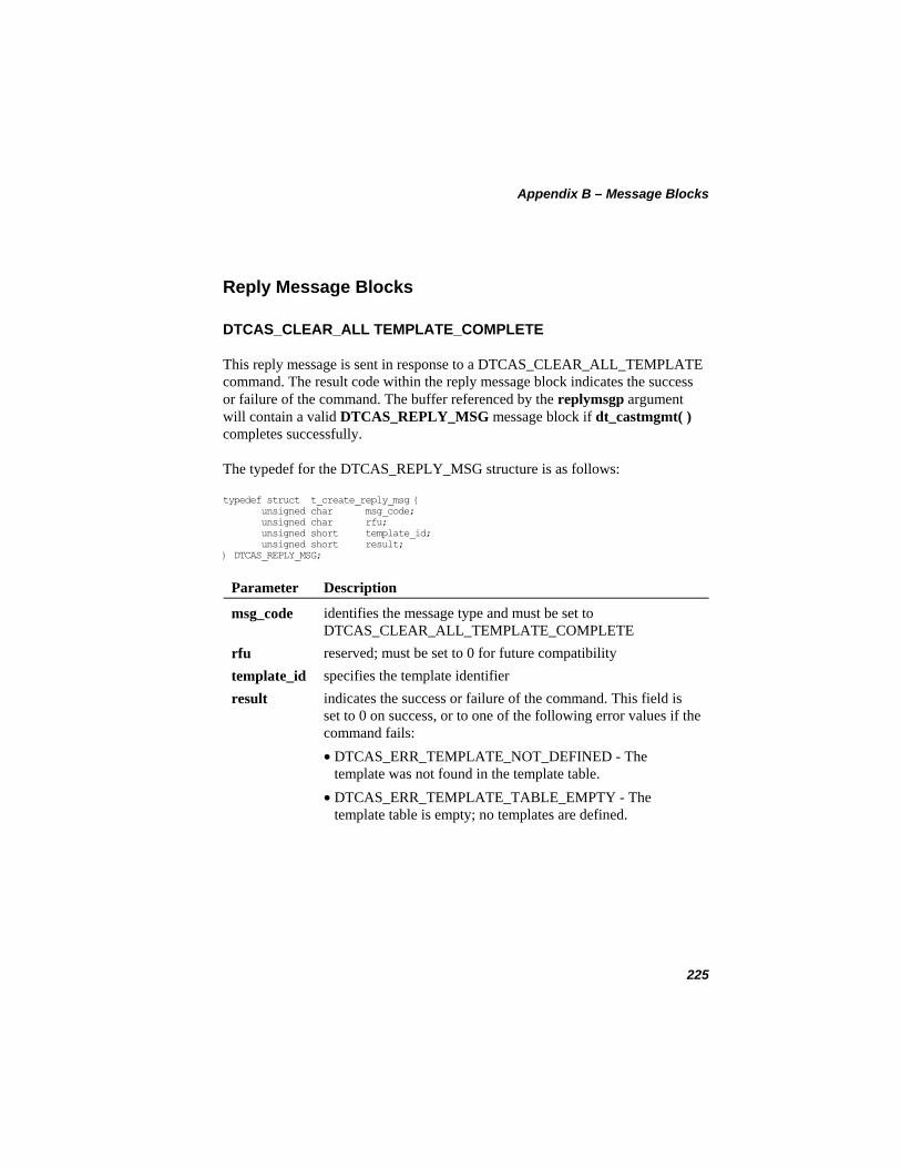
Appendix B – Message Blocks
Reply Message Blocks
DTCAS_CLEAR_ALL TEMPLATE_COMPLETE
This reply message is sent in response to a DTCAS_CLEAR_ALL_TEMPLATE command. The result code within the reply message block indicates the success or failure of the command. The buffer referenced by the replymsgp argument will contain a valid DTCAS_REPLY_MSG message block if dt_castmgmt( ) completes successfully.
The typedef for the DTCAS_REPLY_MSG structure is as follows:
typedef struct t_create_reply_msg { unsigned char msg_code; unsigned char rfu; unsigned short template_id; unsigned short result; } DTCAS_REPLY_MSG;
Parameter Description
identifies the message type and must be set to DTCAS_CLEAR_ALL_TEMPLATE_COMPLETE
msg_code
rfu reserved; must be set to 0 for future compatibility template_id specifies the template identifier result indicates the success or failure of the command. This field is
set to 0 on success, or to one of the following error values if the command fails:
• DTCAS_ERR_TEMPLATE_NOT_DEFINED - The template was not found in the template table.
• DTCAS_ERR_TEMPLATE_TABLE_EMPTY - The template table is empty; no templates are defined.
225
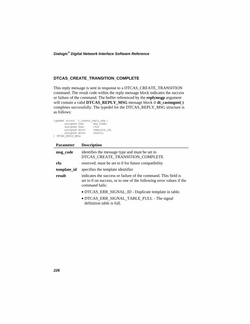
Dialogic® Digital Network Interface Software Reference
DTCAS_CREATE_TRANSITION_COMPLETE
This reply message is sent in response to a DTCAS_CREATE_TRANSITION command. The result code within the reply message block indicates the success or failure of the command. The buffer referenced by the replymsgp argument will contain a valid DTCAS_REPLY_MSG message block if dt_castmgmt( ) completes successfully. The typedef for the DTCAS_REPLY_MSG structure is as follows:
typedef struct t_create_reply_msg { unsigned char msg_code; unsigned char rfu; unsigned short template_id; unsigned short result; } DTCAS_REPLY_MSG;
Parameter Description
identifies the message type and must be set to DTCAS_CREATE_TRANSITION_COMPLETE
msg_code
rfu reserved; must be set to 0 for future compatibility template_id specifies the template identifier result indicates the success or failure of the command. This field is
set to 0 on success, or to one of the following error values if the command fails:
• DTCAS_ERR_SIGNAL_ID - Duplicate template in table. • DTCAS_ERR_SIGNAL_TABLE_FULL - The signal
definition table is full.
226
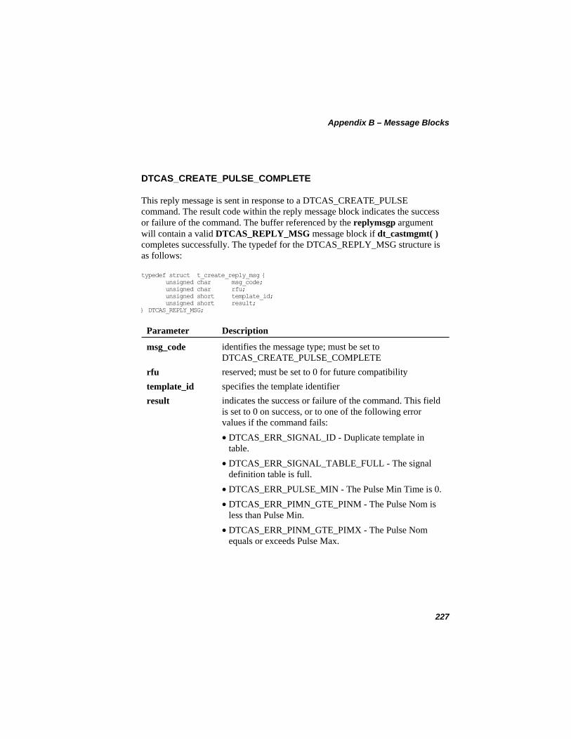
Appendix B – Message Blocks
DTCAS_CREATE_PULSE_COMPLETE
This reply message is sent in response to a DTCAS_CREATE_PULSE command. The result code within the reply message block indicates the success or failure of the command. The buffer referenced by the replymsgp argument will contain a valid DTCAS_REPLY_MSG message block if dt_castmgmt( ) completes successfully. The typedef for the DTCAS_REPLY_MSG structure is as follows:
typedef struct t_create_reply_msg { unsigned char msg_code; unsigned char rfu; unsigned short template_id; unsigned short result; } DTCAS_REPLY_MSG;
Parameter Description
identifies the message type; must be set to DTCAS_CREATE_PULSE_COMPLETE
msg_code
rfu reserved; must be set to 0 for future compatibility template_id specifies the template identifier result indicates the success or failure of the command. This field
is set to 0 on success, or to one of the following error values if the command fails:
• DTCAS_ERR_SIGNAL_ID - Duplicate template in table.
• DTCAS_ERR_SIGNAL_TABLE_FULL - The signal definition table is full.
• DTCAS_ERR_PULSE_MIN - The Pulse Min Time is 0. • DTCAS_ERR_PIMN_GTE_PINM - The Pulse Nom is
less than Pulse Min. • DTCAS_ERR_PINM_GTE_PIMX - The Pulse Nom
equals or exceeds Pulse Max.
227
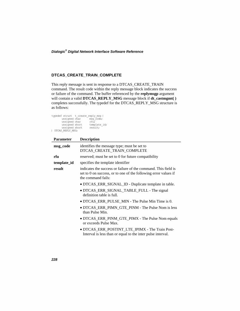
Dialogic® Digital Network Interface Software Reference
DTCAS_CREATE_TRAIN_COMPLETE
This reply message is sent in response to a DTCAS_CREATE_TRAIN command. The result code within the reply message block indicates the success or failure of the command. The buffer referenced by the replymsgp argument will contain a valid DTCAS_REPLY_MSG message block if dt_castmgmt( ) completes successfully. The typedef for the DTCAS_REPLY_MSG structure is as follows:
typedef struct t_create_reply_msg { unsigned char msg_code; unsigned char rfu; unsigned short template_id; unsigned short result; } DTCAS_REPLY_MSG;
Parameter Description
msg_code identifies the message type; must be set to DTCAS_CREATE_TRAIN_COMPLETE
rfu reserved; must be set to 0 for future compatibility template_id specifies the template identifier result indicates the success or failure of the command. This field is
set to 0 on success, or to one of the following error values if the command fails:
• DTCAS_ERR_SIGNAL_ID - Duplicate template in table. • DTCAS_ERR_SIGNAL_TABLE_FULL - The signal
definition table is full. • DTCAS_ERR_PULSE_MIN - The Pulse Min Time is 0. • DTCAS_ERR_PIMN_GTE_PINM - The Pulse Nom is less
than Pulse Min. • DTCAS_ERR_PINM_GTE_PIMX - The Pulse Nom equals
or exceeds Pulse Max. • DTCAS_ERR_POSTINT_LTE_IPIMX - The Train Post-
Interval is less than or equal to the inter pulse interval.
228

Appendix B – Message Blocks
DTCAS_DELETE_TEMPLATE_COMPLETE
This reply message is sent in response to a DTCAS_DELETE_TEMPLATE command. The result code within the reply message block indicates the success or failure of the command. The buffer referenced by the replymsgp argument will contain a valid DTCAS_REPLY_MSG message block if dt_castmgmt( ) completes successfully. The typedef for the DTCAS_REPLY_MSG structure is as follows:
typedef struct t_create_reply_msg { unsigned char msg_code; unsigned char rfu; unsigned short template_id; unsigned short result; } DTCAS_REPLY_MSG;
Parameter Description
identifies the message type; must be set to DTCAS_DELETE_TEMPLATE_COMPLETE
msg_code
rfu reserved; must be set to 0 for future compatibility template_id specifies the template identifier result indicates the success or failure of the command. This field
is set to 0 on success, or to one of the following error values if the command fails:
• DTCAS_ERR_TEMPLATE_NOT_DEFINED - The template was not found in the template table.
• DTCAS_ERR_TEMPLATE_TABLE_EMPTY - The template table is empty; no templates are defined.
229
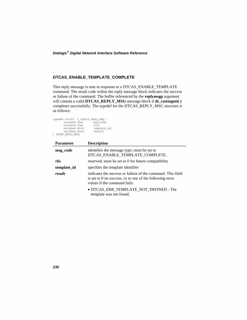
Dialogic® Digital Network Interface Software Reference
DTCAS_ENABLE_TEMPLATE_COMPLETE
This reply message is sent in response to a DTCAS_ENABLE_TEMPLATE command. The result code within the reply message block indicates the success or failure of the command. The buffer referenced by the replymsgp argument will contain a valid DTCAS_REPLY_MSG message block if dt_castmgmt( ) completes successfully. The typedef for the DTCAS_REPLY_MSG structure is as follows:
typedef struct t_create_reply_msg { unsigned char msg_code; unsigned char rfu; unsigned short template_id; unsigned short result; } DTCAS_REPLY_MSG;
Parameter Description
msg_code identifies the message type; must be set to DTCAS_ENABLE_TEMPLATE_COMPLETE.
rfu reserved; must be set to 0 for future compatibility template_id specifies the template identifier result indicates the success or failure of the command. This field
is set to 0 on success, or to one of the following error values if the command fails:
• DTCAS_ERR_TEMPLATE_NOT_DEFINED - The template was not found.
230
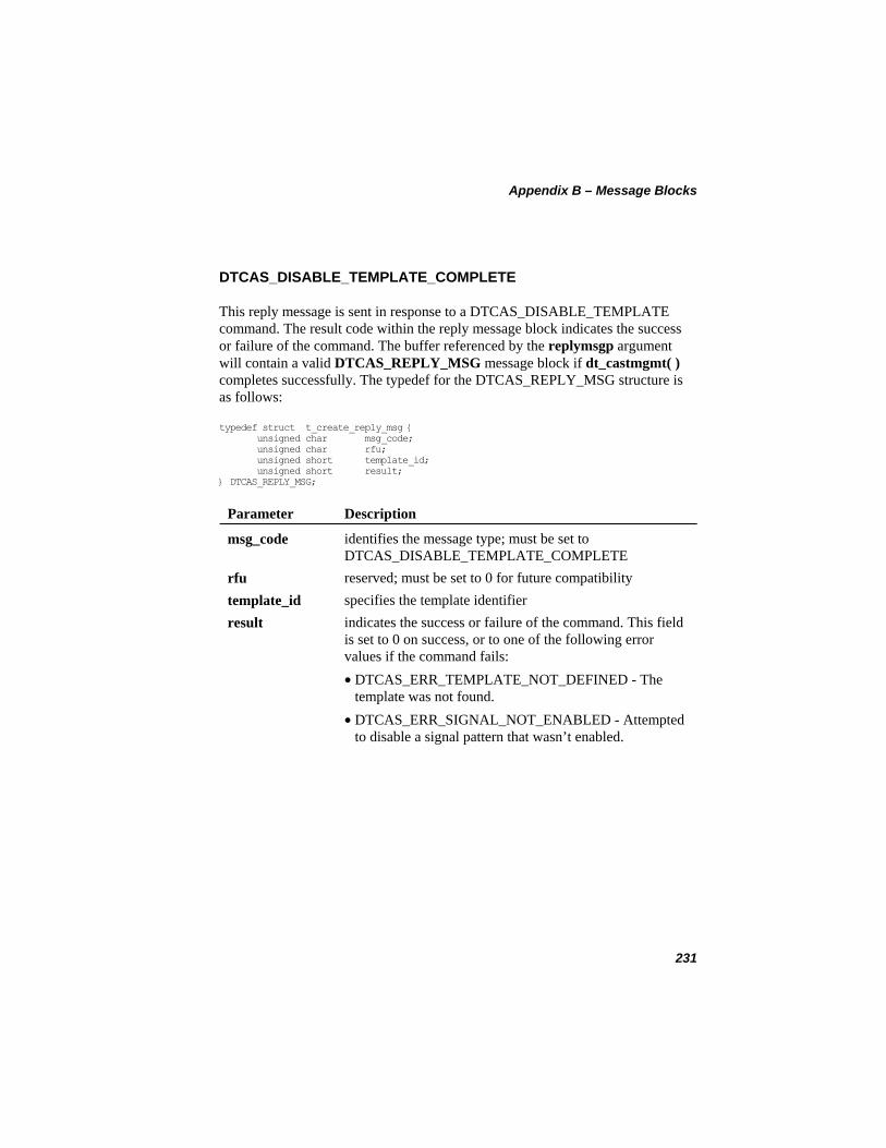
Appendix B – Message Blocks
DTCAS_DISABLE_TEMPLATE_COMPLETE
This reply message is sent in response to a DTCAS_DISABLE_TEMPLATE command. The result code within the reply message block indicates the success or failure of the command. The buffer referenced by the replymsgp argument will contain a valid DTCAS_REPLY_MSG message block if dt_castmgmt( ) completes successfully. The typedef for the DTCAS_REPLY_MSG structure is as follows:
typedef struct t_create_reply_msg { unsigned char msg_code; unsigned char rfu; unsigned short template_id; unsigned short result; } DTCAS_REPLY_MSG;
Parameter Description
identifies the message type; must be set to DTCAS_DISABLE_TEMPLATE_COMPLETE
msg_code
rfu reserved; must be set to 0 for future compatibility template_id specifies the template identifier result indicates the success or failure of the command. This field
is set to 0 on success, or to one of the following error values if the command fails:
• DTCAS_ERR_TEMPLATE_NOT_DEFINED - The template was not found.
• DTCAS_ERR_SIGNAL_NOT_ENABLED - Attempted to disable a signal pattern that wasn’t enabled.
231
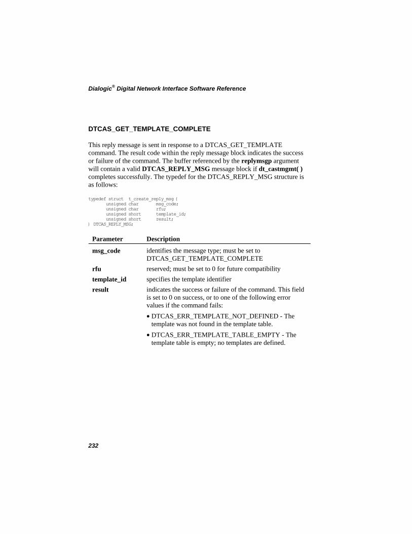
Dialogic® Digital Network Interface Software Reference
DTCAS_GET_TEMPLATE_COMPLETE
This reply message is sent in response to a DTCAS_GET_TEMPLATE command. The result code within the reply message block indicates the success or failure of the command. The buffer referenced by the replymsgp argument will contain a valid DTCAS_REPLY_MSG message block if dt_castmgmt( ) completes successfully. The typedef for the DTCAS_REPLY_MSG structure is as follows:
typedef struct t_create_reply_msg { unsigned char msg_code; unsigned char rfu; unsigned short template_id; unsigned short result; } DTCAS_REPLY_MSG;
Parameter Description
identifies the message type; must be set to DTCAS_GET_TEMPLATE_COMPLETE
msg_code
rfu reserved; must be set to 0 for future compatibility template_id specifies the template identifier result indicates the success or failure of the command. This field
is set to 0 on success, or to one of the following error values if the command fails:
• DTCAS_ERR_TEMPLATE_NOT_DEFINED - The template was not found in the template table.
• DTCAS_ERR_TEMPLATE_TABLE_EMPTY - The template table is empty; no templates are defined.
232
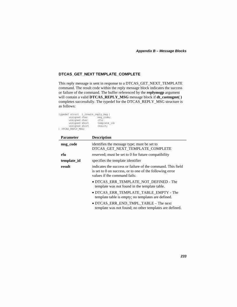
Appendix B – Message Blocks
DTCAS_GET_NEXT TEMPLATE_COMPLETE
This reply message is sent in response to a DTCAS_GET_NEXT_TEMPLATE command. The result code within the reply message block indicates the success or failure of the command. The buffer referenced by the replymsgp argument will contain a valid DTCAS_REPLY_MSG message block if dt_castmgmt( ) completes successfully. The typedef for the DTCAS_REPLY_MSG structure is as follows:
typedef struct t_create_reply_msg { unsigned char msg_code; unsigned char rfu; unsigned short template_id; unsigned short result; } DTCAS_REPLY_MSG;
Parameter Description
identifies the message type; must be set to DTCAS_GET_NEXT_TEMPLATE_COMPLETE
msg_code
rfu reserved; must be set to 0 for future compatibility template_id specifies the template identifier result indicates the success or failure of the command. This field
is set to 0 on success, or to one of the following error values if the command fails:
• DTCAS_ERR_TEMPLATE_NOT_DEFINED - The template was not found in the template table.
• DTCAS_ERR_TEMPLATE_TABLE_EMPTY - The template table is empty; no templates are defined.
• DTCAS_ERR_END_TMPL_TABLE – The next template was not found; no other templates are defined.
233
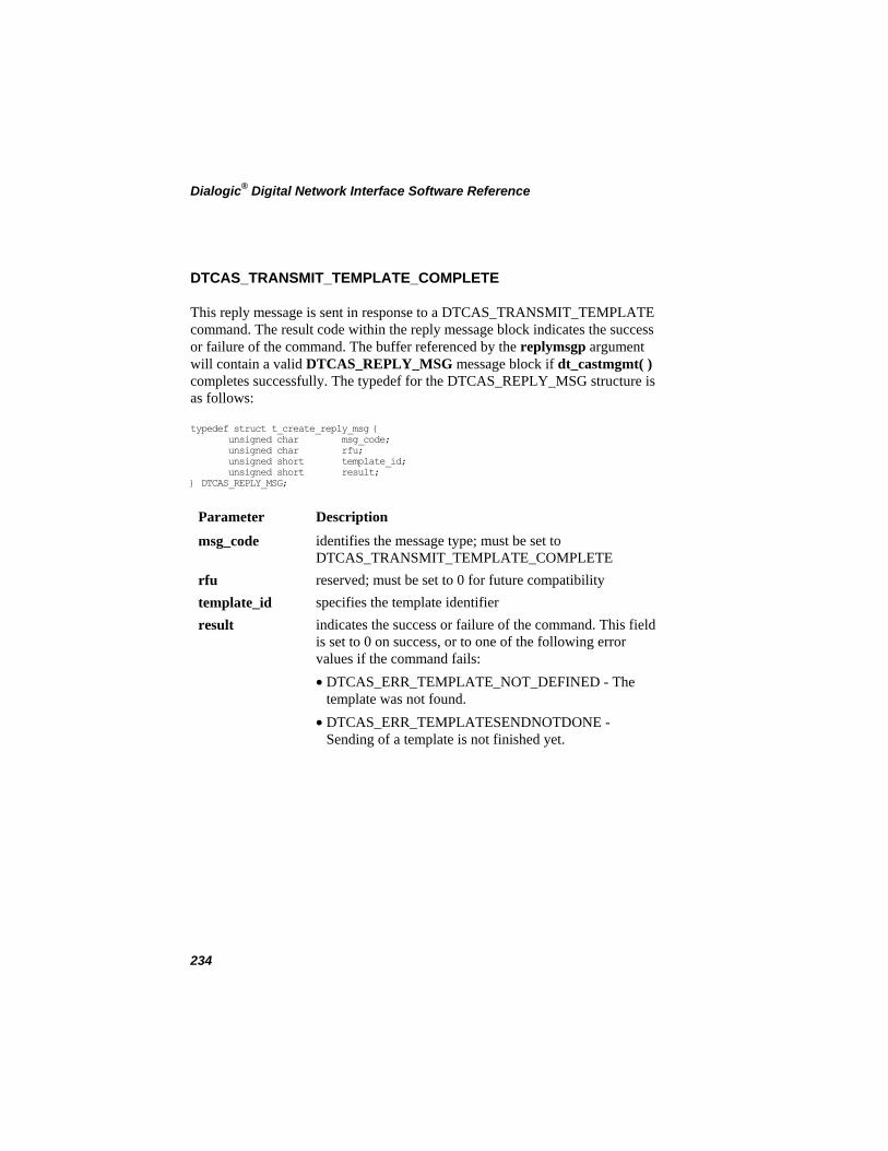
Dialogic® Digital Network Interface Software Reference
DTCAS_TRANSMIT_TEMPLATE_COMPLETE
This reply message is sent in response to a DTCAS_TRANSMIT_TEMPLATE command. The result code within the reply message block indicates the success or failure of the command. The buffer referenced by the replymsgp argument will contain a valid DTCAS_REPLY_MSG message block if dt_castmgmt( ) completes successfully. The typedef for the DTCAS_REPLY_MSG structure is as follows:
typedef struct t_create_reply_msg { unsigned char msg_code; unsigned char rfu; unsigned short template_id; unsigned short result; } DTCAS_REPLY_MSG;
Parameter Description
msg_code identifies the message type; must be set to DTCAS_TRANSMIT_TEMPLATE_COMPLETE
rfu reserved; must be set to 0 for future compatibility template_id specifies the template identifier result indicates the success or failure of the command. This field
is set to 0 on success, or to one of the following error values if the command fails:
• DTCAS_ERR_TEMPLATE_NOT_DEFINED - The template was not found.
• DTCAS_ERR_TEMPLATESENDNOTDONE - Sending of a template is not finished yet.
234
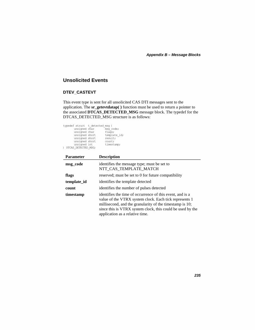
Appendix B – Message Blocks
Unsolicited Events
DTEV_CASTEVT
This event type is sent for all unsolicited CAS DTI messages sent to the application. The sr_getevtdatap( ) function must be used to return a pointer to the associated DTCAS_DETECTED_MSG message block. The typedef for the DTCAS_DETECTED_MSG structure is as follows:
typedef struct t_detected_msg { unsigned char msg_code; unsigned char flags; unsigned short template_id; unsigned short result; unsigned short count; unsigned int timestamp; } DTCAS_DETECTED_MSG;
Parameter Description
identifies the message type; must be set to NTT_CAS_TEMPLATE_MATCH
msg_code
flags reserved; must be set to 0 for future compatibility template_id identifies the template detected count identifies the number of pulses detected timestamp identifies the time of occurrence of this event, and is a
value of the VTRX system clock. Each tick represents 1 millisecond, and the granularity of the timestamp is 10; since this is VTRX system clock, this could be used by the application as a relative time.
235
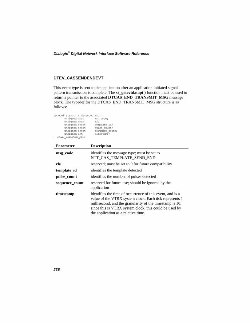
Dialogic® Digital Network Interface Software Reference
DTEV_CASSENDENDEVT
This event type is sent to the application after an application initiated signal pattern transmission is complete. The sr_getevtdatap( ) function must be used to return a pointer to the associated DTCAS_END_TRANSMIT_MSG message block. The typedef for the DTCAS_END_TRANSMIT_MSG structure is as follows:
typedef struct t_detected_msg { unsigned char msg_code; unsigned char rfu; unsigned short template_id; unsigned short pulse_count; unsigned short sequence_count; unsigned int timestamp; } DTCAS_DETECTED_MSG;
Parameter Description
identifies the message type; must be set to NTT_CAS_TEMPLATE_SEND_END
msg_code
rfu reserved; must be set to 0 for future compatibility template_id identifies the template detected pulse_count identifies the number of pulses detected sequence_count reserved for future use; should be ignored by the
application timestamp identifies the time of occurrence of this event, and is a
value of the VTRX system clock. Each tick represents 1 millisecond, and the granularity of the timestamp is 10; since this is VTRX system clock, this could be used by the application as a relative time.
236
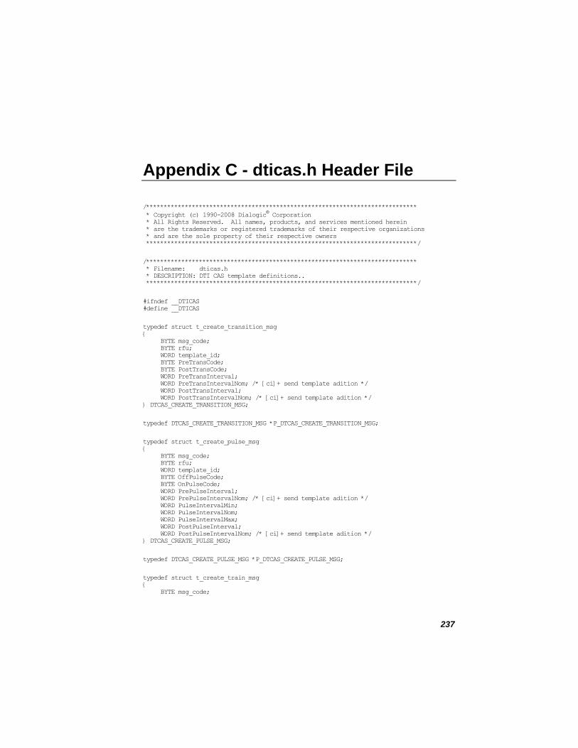
Appendix C - dticas.h Header File
/***************************************************************************** * Copyright (c) 1990-2008 Dialogic® Corporation * All Rights Reserved. All names, products, and services mentioned herein * are the trademarks or registered trademarks of their respective organizations * and are the sole property of their respective owners *****************************************************************************/
/***************************************************************************** * Filename: dticas.h * DESCRIPTION: DTI CAS template definitions.. *****************************************************************************/
#ifndef __DTICAS #define __DTICAS
typedef struct t_create_transition_msg { BYTE msg_code; BYTE rfu; WORD template_id; BYTE PreTransCode; BYTE PostTransCode; WORD PreTransInterval; WORD PreTransIntervalNom; /* [ci]+ send template adition */ WORD PostTransInterval; WORD PostTransIntervalNom; /* [ci]+ send template adition */ } DTCAS_CREATE_TRANSITION_MSG;
typedef DTCAS_CREATE_TRANSITION_MSG *P_DTCAS_CREATE_TRANSITION_MSG;
typedef struct t_create_pulse_msg { BYTE msg_code; BYTE rfu; WORD template_id; BYTE OffPulseCode; BYTE OnPulseCode; WORD PrePulseInterval; WORD PrePulseIntervalNom; /* [ci]+ send template adition */ WORD PulseIntervalMin; WORD PulseIntervalNom; WORD PulseIntervalMax; WORD PostPulseInterval; WORD PostPulseIntervalNom; /* [ci]+ send template adition */ } DTCAS_CREATE_PULSE_MSG;
typedef DTCAS_CREATE_PULSE_MSG *P_DTCAS_CREATE_PULSE_MSG;
typedef struct t_create_train_msg { BYTE msg_code;
237
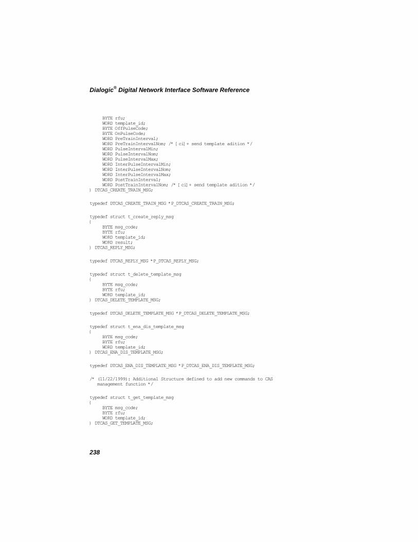
Dialogic® Digital Network Interface Software Reference
BYTE rfu; WORD template_id; BYTE OffPulseCode; BYTE OnPulseCode; WORD PreTrainInterval; WORD PreTrainIntervalNom; /* [ci]+ send template adition */ WORD PulseIntervalMin; WORD PulseIntervalNom; WORD PulseIntervalMax; WORD InterPulseIntervalMin; WORD InterPulseIntervalNom; WORD InterPulseIntervalMax; WORD PostTrainInterval; WORD PostTrainIntervalNom; /* [ci]+ send template adition */ } DTCAS_CREATE_TRAIN_MSG;
typedef DTCAS_CREATE_TRAIN_MSG *P_DTCAS_CREATE_TRAIN_MSG;
typedef struct t_create_reply_msg { BYTE msg_code; BYTE rfu; WORD template_id; WORD result; } DTCAS_REPLY_MSG;
typedef DTCAS_REPLY_MSG *P_DTCAS_REPLY_MSG;
typedef struct t_delete_template_msg { BYTE msg_code; BYTE rfu; WORD template_id; } DTCAS_DELETE_TEMPLATE_MSG;
typedef DTCAS_DELETE_TEMPLATE_MSG *P_DTCAS_DELETE_TEMPLATE_MSG;
typedef struct t_ena_dis_template_msg { BYTE msg_code; BYTE rfu; WORD template_id; } DTCAS_ENA_DIS_TEMPLATE_MSG;
typedef DTCAS_ENA_DIS_TEMPLATE_MSG *P_DTCAS_ENA_DIS_TEMPLATE_MSG;
/* (11/22/1999): Additional Structure defined to add new commands to CAS management function */
typedef struct t_get_template_msg { BYTE msg_code; BYTE rfu; WORD template_id; } DTCAS_GET_TEMPLATE_MSG;
238
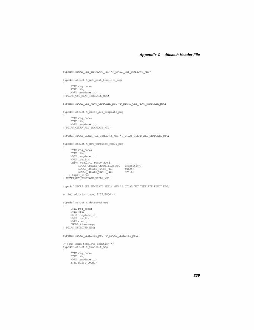
Appendix C – dticas.h Header File
typedef DTCAS_GET_TEMPLATE_MSG *P_DTCAS_GET_TEMPLATE_MSG;
typedef struct t_get_next_template_msg { BYTE msg_code; BYTE rfu; WORD template_id; } DTCAS_GET_NEXT_TEMPLATE_MSG;
typedef DTCAS_GET_NEXT_TEMPLATE_MSG *P_DTCAS_GET_NEXT_TEMPLATE_MSG;
typedef struct t_clear_all_template_msg { BYTE msg_code; BYTE rfu; WORD template_id; } DTCAS_CLEAR_ALL_TEMPLATE_MSG;
typedef DTCAS_CLEAR_ALL_TEMPLATE_MSG *P_DTCAS_CLEAR_ALL_TEMPLATE_MSG;
typedef struct t_get_template_reply_msg { BYTE msg_code; BYTE rfu; WORD template_id; WORD result; union template_reply_msg { DTCAS_CREATE_TRANSITION_MSG transition; DTCAS_CREATE_PULSE_MSG pulse; DTCAS_CREATE_TRAIN_MSG train; } tmplt_info; } DTCAS_GET_TEMPLATE_REPLY_MSG;
typedef DTCAS_GET_TEMPLATE_REPLY_MSG *P_DTCAS_GET_TEMPLATE_REPLY_MSG;
/* End addition dated 1/27/2000 */
typedef struct t_detected_msg { BYTE msg_code; BYTE rfu; WORD template_id; WORD result; WORD count; DWORD timestamp; } DTCAS_DETECTED_MSG;
typedef DTCAS_DETECTED_MSG *P_DTCAS_DETECTED_MSG;
/* [ci] send template addition */ typedef struct t_transmit_msg { BYTE msg_code; BYTE rfu; WORD template_id; BYTE pulse_count;
239
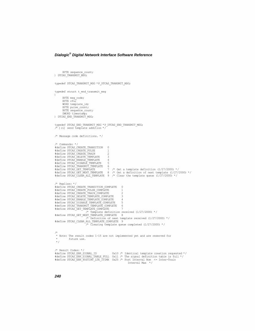
Dialogic® Digital Network Interface Software Reference
BYTE sequence_count; } DTCAS_TRANSMIT_MSG;
typedef DTCAS_TRANSMIT_MSG *P_DTCAS_TRANSMIT_MSG;
typedef struct t_end_transmit_msg { BYTE msg_code; BYTE rfu; WORD template_id; BYTE pulse_count; BYTE sequence_count; DWORD timestamp; } DTCAS_END_TRANSMIT_MSG;
typedef DTCAS_END_TRANSMIT_MSG *P_DTCAS_END_TRANSMIT_MSG; /* [ci] send template addition */
/* Message code definitions. */
/* Commands: */ #define DTCAS_CREATE_TRANSITION 0 #define DTCAS_CREATE_PULSE 1 #define DTCAS_CREATE_TRAIN 2 #define DTCAS_DELETE_TEMPLATE 3 #define DTCAS_ENABLE_TEMPLATE 4 #define DTCAS_DISABLE_TEMPLATE 5 #define DTCAS_TRANSMIT_TEMPLATE 6 #define DTCAS_GET_TEMPLATE 7 /* Get a template definition (1/27/2000) */ #define DTCAS_GET_NEXT_TEMPLATE 8 /* Get a definition of next template (1/27/2000) */ #define DTCAS_CLEAR_ALL_TEMPLATE 9 /* Clear the template queue (1/27/2000) */
/* Replies: */ #define DTCAS_CREATE_TRANSITION_COMPLETE 0 #define DTCAS_CREATE_PULSE_COMPLETE 1 #define DTCAS_CREATE_TRAIN_COMPLETE 2 #define DTCAS_DELETE_TEMPLATE_COMPLETE 3 #define DTCAS_ENABLE_TEMPLATE_COMPLETE 4 #define DTCAS_DISABLE_TEMPLATE_COMPLETE 5 #define DTCAS_TRANSMIT_TEMPLATE_COMPLETE 6 #define DTCAS_GET_TEMPLATE_COMPLETE 7 /* Template definition received (1/27/2000) */ #define DTCAS_GET_NEXT_TEMPLATE_COMPLETE 8 /* Definition of next template received (1/27/2000) */ #define DTCAS_CLEAR_ALL_TEMPLATE_COMPLETE 9 /* Clearing template queue completed (1/27/2000) */
/* * Note: The result codes 1-15 are not implemented yet and are reserved for * future use. */
/* Result Codes: */ #define DTCAS_ERR_SIGNAL_ID 0x10 /* Identical template creation requested */ #define DTCAS_ERR_SIGNAL_TABLE_FULL 0x11 /* The signal definition table is full */ #define DTCAS_ERR_POSTINT_LTE_ITIMX 0x25 /* Post Interval Nom <= Inter-Train Interval Max */
240
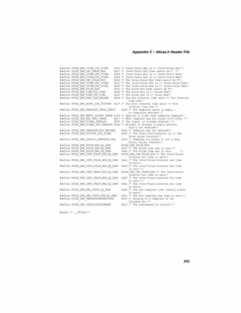
Appendix C – dticas.h Header File
#define DTCAS_ERR_ITIMX_LTE_IPIMX 0x26 /* Inter-Train Max is <= Inter-Pulse Max */ #define DTCAS_ERR_INT_TRAIN_MIN 0x27 /* Inter-Train Min Time cannot be 0 */ #define DTCAS_ERR_ITIMN_GTE_ITINM 0x28 /* Inter-Train Min is >= Inter-Train Nom*/ #define DTCAS_ERR_ITINM_GTE_ITIMX 0x29 /* Inter-Train Nom is >= Inter-Train Max*/ #define DTCAS_ERR_INT_PULSE_MIN 0x30 /* The Inter-Pulse Min Time cannot be 0*/ #define DTCAS_ERR_IPIMN_GTE_IPINM 0x31 /* The Inter-Pulse Min is >= Inter-Pulse Nom*/ #define DTCAS_ERR_IPINM_GTE_IPIMX 0x32 /* The Inter-Pulse Nom is >= Inter-Pulse Max*/ #define DTCAS_ERR_PULSE_MIN 0x33 /* The Pulse Min Time cannot be 0*/ #define DTCAS_ERR_PIMN_GTE_PINM 0x34 /* The Pulse Min is >= Pulse Nom*/ #define DTCAS_ERR_PINM_GTE_PIMX 0x35 /* The Pulse Nom is >= Pulse Max*/ #define DTCAS_ERR_PREI_LTE_PREINM 0x36 /* The Pre Interval time (min) >= Pre Interval time nom*/ #define DTCAS_ERR_POSTI_LTE_POSTINM 0x37 /* The Post Interval time (min) >= Post Interval time nom */ #define DTCAS_ERR_TEMPLATE_TABLE_EMPTY 0x38 /* The Template table is empty - no templates defined */ #define DTCAS_ERR_EMPTY_SIGPAT_TABLE 0x39 /* Applies to a get next template command*/ #define DTCAS_ERR_END_TMPL_TABLE 0x17 /* Next template was not found (1/27/2000) */ #define DTCAS_ERR_SIGNAL_ENABLED 0x0f /* The signal is already enabled. */ #define DTCAS_ERR_SIGNAL_NOT_ENABLED 0x3a /* Attempt to disable a signal pattern that's not enabled*/ #define DTCAS_ERR_TEMPLATE_NOT_DEFINED 0x3b /* Template was not defined*/ #define DTCAS_ERR_POSTINT_LTE_IPIMX 0x3c /* The Train Post-Interval is <= the inter pulse interval*/ #define DTCAS_ERR_INVALID_TEMPLATE_REQ 0x3d /* Template to create is not a Seq, Train, Pulse, Transit*/ #define DTCAS_ERR_PULSE_MIN_EQ_ZERO DTCAS_ERR_PULSE_MIN #define DTCAS_ERR_PULSE_NOM_EQ_ZERO 0x3f /* The Pulse time nom is zero */ #define DTCAS_ERR_PULSE_MAX_EQ_ZERO 0x4a /* The Pulse time max is zero */ #define DTCAS_ERR_INTR_PULSE_MIN_EQ_ZERO DTCAS_ERR_INT_PULSE_MIN /* The Inter-Pulse- interval min time is zero*/ #define DTCAS_ERR_INTR_PULSE_NOM_EQ_ZERO 0x4c /* The Inter-Pulse-interval nom time is zero*/ #define DTCAS_ERR_INTR_PULSE_MAX_EQ_ZERO 0x4d /* The Inter-Pulse-interval max time is zero */ #define DTCAS_ERR_INTR_TRAIN_MIN_EQ_ZERO DTCAS_ERR_INT_TRAIN_MIN /* The Inter-Train- interval min time is zero*/ #define DTCAS_ERR_INTR_TRAIN_NOM_EQ_ZERO 0x4f /* The Inter-Train-interval min time is zero */ #define DTCAS_ERR_INTR_TRAIN_MAX_EQ_ZERO 0x5a /* The Inter-Train-interval min time is zero*/ #define DTCAS_ERR_PRE_INTRV_EQ_ZERO 0x5b /* The Pre template time (really a min) is zero*/ #define DTCAS_ERR_PRE_INTRV_NOM_EQ_ZERO 0x5c /* The Pre template nom time is zero */ #define DTCAS_ERR_TEMPLATESENDNOTDONE 0x16 /* Sending of a template is not finished yet */ #define DTCAS_ERR_INVALIDSUBCOMMAND 0x12 /* The subcommand is invalid */
#endif /* __DTICAS */
241

Dialogic® Digital Network Interface Software Reference
242
Appendix D - Related Publications
This section lists publications you should refer to for additional information on creating digital network interface applications.
• Dialogic® Global Call API Programming Guide
• Dialogic® Global Call API Library Reference
• Dialogic® Voice API Programming Guide
• Dialogic® Voice API Library Reference
• Dialogic® Standard Runtime Library API Programming Guide
• Dialogic® Standard Runtime Library API Library Reference
• Dialogic® Audio Conferencing API Programming Guide
• Dialogic® Audio Conferencing API Library Reference
• Dialogic® Modular Station Interface API Programming Guide
• Dialogic® Modular Station Interface API Library Reference
243

Dialogic® Digital Network Interface Software Reference
244
Glossary
A-law: A pulse-code modulation (PCM) algorithm used in digitizing telephone audio signals in E1 areas.
ANI: Automatic Number Identification. A feature of certain telecommunications networking protocols or processes that allows the caller’s phone number to be detected and displayed by the called party.
asynchronous function: On Linux platforms, a function that allows program execution to continue without waiting for a task to complete. To implement an asynchronous function, an application defined event handler must be enabled to trap and process the completion event. See synchronous function.
B8ZS: Binary 8-zero Substitution. Basic bipolar coding algorithm for digital telephony. At the transmitting end, a string of 8 zeros is deliberately replaced with a pulse that produces a bipolar violation. At the receiving end, bipolar violations are replaced with a string of 8 zeros.
BLT: Board Locator Technology. Operates in conjunction with a rotary switch to determine and set non-conflicting slot and IRQ interrupt-level parameters, thus eliminating the need to set jumpers or DIP switches.
buffer: A block of memory or temporary storage device that holds data until it can be processed. It is used to compensate for the difference in the rate of the flow of information (or time occurrence of events) when transmitting data from one device to another.
CAS: Channel Associated Signaling. The signaling protocol used with the CEPT E1 telephony standard. In CAS, one of the 32 channels, time slot 16, is dedicated to signaling for all of the 30 voice channels. Unlike T1 systems, which use robbed-bit signaling, telephony systems using CAS are considered examples of out-of-band signaling. See in-band signaling, robbed-bit signaling.
CCITT: International Telephone and Telegraph Consultative Committee, a part of the ICU (International Telecommunications Union) responsible for formulating telephony and other standards, such as E1.
245
Dialogic® Digital Network Interface Software Reference
CEPT: Conference of European Postal and Telecommunications administrations. Defines how bits of a PCM carrier system in E1 areas will be used and in what sequence. CEPT format consists of 30 voice channels, one signaling channel, and one framing (synchronization) channel. See E1.
CO: Central Office. The telephone company facility where subscriber lines are linked, through switches, to other subscriber lines (including local and long distance lines).
CRC: Cyclic Redundancy Check. A basic error checking mechanism for digital transmissions in which a CRC character, indicating the number of bits in a block of data, is included in the transmission. The receiving end calculates the number of bits in the block independently and compares the result to the received CRC character. CRC4 is a specific algorithm used to implement error checking.
crossover cable: A cable used to interconnect two network boards, often to join two T1 or E1 lines. The cable is split and folded so that the lines carrying network receive data on one side of the crossover connector mate with network transmit lines on the other side of the crossover.
device: A computer peripheral or component that is controlled through a software device driver. A digital network interface board is considered a physical board containing one or more logical board devices, and each time slot on the board is a time slot device.
device channel: A voice data path that processes one incoming or outgoing call at a time (equivalent to the terminal equipment terminating a phone line). Compare time slot.
DNIS: Dialed Number Identification Service. An 800 service feature that allows a business to determine the geographical area from which a call originated by the digits dialed (a different phone number is made available to callers in each region).
drop-and-insert: A system configuration in which two network boards are interconnected by a crossover cable and continuously pass all time slots through to each other. A time slot from one network can be “dropped” to a resource module for processing. In return, the resource module can “insert” signaling and audio into the bit stream received from the other side of the crossover connector. (A resource module can insert only to the network board on the same side of the crossover.)
246
Glossary
This bit stream is applied through the network module for outbound transmission to the attached network span.
E1: Another name given to the CEPT digital telephony format devised by the CCITT. See CEPT.
E&M protocol: A signaling protocol that defines the sending and receiving of signals. E&M protocol is the most common protocol on T1 trunks.
event: An unsolicited or asynchronous communication from a hardware device to an operating system, application, or driver. Events are generally attention getting messages, allowing a process to decide when and where to redirect its resources.
event handler: A portion of an application program designed to trap and control processing of device-specific events. The rules for creating a digital network interface event handler are the same as those for creating a Linux signal handler.
Extended Attribute functions: Class of functions that take one input parameter (a valid device handle) and return device-specific information. For instance, a digital network interface Linux Extended Attribute function returns information specific to the digital network interface class of devices. Extended Attribute function names are case-sensitive and must be in capital letters. See Standard Attribute functions.
firmware: A set of program instructions that reside on an expansion board, usually in EPROM.
fixed routing In this configuration, the resource devices (voice/fax) and network interface devices are permanently coupled together in a fixed configuration. Only the network interface time slot device has access to the CT Bus. Used in Dialogic® DM3 architecture.
flexible routing In this configuration, the resource devices (voice/fax) and network interface devices are independent, which allows exporting and sharing of the resources. All resources have access to the CT Bus. Used in Dialogic® DM3 architecture.
in-band signaling: 1. In an analog telephony circuit, in-band refers to signaling that occupies the same transmission path and frequency band used to transmit voice tones. 2. In digital telephony, “in-band” has
247
Dialogic® Digital Network Interface Software Reference
come to mean signaling that is transmitted within an 8-bit voice sample or time slot, as in T1 “robbed-bit” signaling.
IRQ: Interrupt request. A signal sent to the central processing unit (CPU) to temporarily suspend normal processing and transfer control to an interrupt handling routine. Interrupts may be generated by conditions such as completion of an I/O process, detection of hardware failure, power failures, etc.
mu-law: 1. A pulse code modulation (PCM) algorithm used in digitizing telephone audio signals in T1 areas. 2. The PCM coding and compounding standard used in Japan and North America.
PSTN: Public Switched Telephone Network.
robbed-bit signaling: The type of signaling protocol implemented in areas using the T1 telephony standard. In robbed-bit signaling, signaling information is carried in-band, within the 8-bit voice samples. These bits are later stripped away, or “robbed,” to produce the signaling information for each of the 24 time slots. See CAS, in-band signaling.
route: Assign a resource to a time slot.
SCbus: Signal Computing bus. The TDM (Time Division Multiplexed) resource sharing bus that allows information to be transmitted and received among resources over multiple data lines. A hardwired connection between switch handlers on SCbus based products for transmitting information over 1024 time slots to all devices connected to the SCbus.
SCSA: Signal Computing System Architecture.
Signal Computer System Architecture: SCSA. A standard open development platform. An open hardware and software standard that incorporates virtually every other standard in PC-based switching. All signaling is out-of-band. In addition, SCSA offers time slot bundling and allows for scalability.
signaling insertion: Mode in which the digital network interface (or any network board) overwrites signaling data from resource modules in order to perform signaling to the network.
248
Glossary
249
SRL: Dialogic® Standard Runtime Library. A software resource containing Event Management functions, Standard Attribute functions, and data structures used by all devices, but which return data unique to the device.
Standard Attribute functions: Class of functions that take one input parameter (a valid device handle) and return generic information about the device. For instance, Standard Attribute functions return IRQ and error information for all device types. Standard Attribute function names are case-sensitive and must be in capital letters. Standard Attribute functions for all devices are contained in the SRL. See Extended Attribute functions.
synchronous function: On Linux platforms, a function that blocks program execution until a value is returned by the device. Also called a blocking function. See asynchronous function.
time slot: In a digital telephony environment, a normally continuous and individual communication (for example, someone speaking on a telephone) is (1) digitized, (2) broken up into pieces consisting of a fixed number of bits, (3) combined with pieces of other individual communications in a regularly repeating, timed sequence (multiplexed), and (4) transmitted serially over a single telephone line. Each individual digitized communication is called a time slot. In T1 areas, 24 time slots are multiplexed onto a single twisted-wire pair. In E1 areas, 32 time slots are multiplexed together. Compare device channel.
time slot assignment: The ability to route the digital information contained in a time slot to a specific device channel. See device channel.
wink: In T1 or E1 systems, a signaling bit transition from on to off, or off to on, and back again to the original state. In T1 systems, the wink signal can be transmitted on either the A or B signaling bit. In E1 systems, the wink signal can be transmitted on either the A, B, C, or D signaling bit. Using either system, the choice of signaling bit and wink polarity (on-off-on or off-on-off hook) is configurable through digital network interface board download parameters.

Index
compiling, 192 A D aborting an application, 192
advanced features, 192 D4 frame, 18
Agent automation, 13 D4 superframe, 18
alarm device handle, 126 transmission to network, 169
device parameter, 146 Alarm functions, 32
device parameters alarm handling, 181 See dt_getparm( ), 107
E1, 15 Diagnostic functions, 32 hardware alarm indicators, 30
mode, 134 diagnostics, 129 testing communications, 158 asynchronous, 89 testing I/O interface, 162
asynchronous mode, 31 dialing, 14
Audiotex, 13 Direct dial-in (DDI) service, 13
B directory assistance See Operator services, 13 backward compatibility, 14
distant multiframe alarm, 28 billing automation See Operator services, 13 drop-and-insert configuration, 13
blue alarm, 27 DS-0, 17
C DS-1, 17
dt_getctinfo( ), 94 CAS, 23
dt_getevtmsk( ), 197 Cellular messaging, 13
dt_getxmitslot( ), 119 Central-office-based voice mail See CO-based voice mail, 13 dt_listen( ), 122
CEPT, 23 dt_unlisten( ), 166 Channel Associated Signaling dtilib.h, 39 See CAS, 23
closing devices, 87
251
Dialogic® Digital Network Interface Software Reference
See ATDT_IDLEST( ), 54 E idling, 143 E&M, 20 include files, 177 E1 frame, 20 initialize time slots, 182 EPROM
See ATDT_ROMVER( ), 57 intercept treatments version, 57 See Operator services, 13
event mask, 102 L values, 104 LEDs, 30 events
event bitmask linking, 192 See event mask, 102
N event management, 13
Extended Attribute functions, 33 network interface library supported functions, 195
F O
firmware See ATDT_DNLDVER( ), 49 opening time slots, 14 version, 49
Operator services, 13 function
P dt_getctinfo( ), 94 dt_getxmitslot( ), 119 Parameter Request functions, 33 dt_listen( ), 122 dt_unlisten( ), 166 Parameter Setting functions, 33
function library R See also Voice library, 14
red alarm, 27 functions supported
remote alarm, 28 network interface library, 195
Resource Management functions, 33 H robbed-bit signaling, 19 hardware compatibility
backward compatibility, 14 S hardware configuration, 180 SC_TSINFO, 123 header files, 177 SCbus
routing, 26 I routing functions, 34
idle state terminology, 15
252
Index
SCbus routing functions, 34 signaling bits, 68 signaling mode, 65
Service bureaus, 13 Time Slot Audio functions, 34
signaling E1 national/international bits, 25 Time Slot Signaling functions, 35 mode, 42
time slot status See ATDT_BDMODE( ), 42 See ATDT_STATUS, 62 T1, 19
transparent signaling mode, 15 signaling all 1s alarm, 29 See also signaling mode, 15
signaling bits, 155 U See ATDT_TSSGBIT( ), 68
transmit, 152 unframed all 1s alarm, 28 signaling insertion mode, 149 V signaling mode
Voice library, 14 See ATDT_TSMODE( ), 65
W silence, 143
SRL, 13, 32 wink signaling, 172
Standard Attribute functions Y See SRL, 32
yellow alarm, 27 Standard Runtime Library see SRL, 13
supported functions network interface library, 195
synchronization T1, 19
synchronous, 158
synchronous mode, 31
T Telemarketing, 13
terminate configuration, 13
tests, 158, 162
time division multiplexing, 18
time slot
253