Embed Size (px)
Citation preview
Arch Appl Mech (2017) 87:801–815DOI 10.1007/s00419-016-1202-0
SPECIAL
Wojciech Sawczuk · Grzegorz M. Szymanski
Diagnostics of the railway friction disc brake basedon the analysis of the vibration signals in termsof resonant frequency
Received: 13 March 2016 / Accepted: 26 October 2016 / Published online: 9 November 2016© The Author(s) 2016. This article is published with open access at Springerlink.com
Abstract Increasing the speed of trains forces the application of a greater braking power, i.e. the capabilityof the brake system of rapidly absorbing and dispersing the stored heat energy. The instability of operationresults from the occurrence of vibrations on the friction component, which affects the efficiency of the brakingprocess. In practice, it means that when braking, the vehicle variable friction resistance may lead to an unevenbraking process. The effects of such changes can be manifested in the form of vibrations with high inputamplitude. The vibrations generated by the working components are distributed throughout the vehicle, whichalso adversely affects the driving comfort. The purpose of this paper is to determine the resonant frequencies ofselected components of the railway disc brake. This paper presents a method of assessing the thickness of thebrake pads of a railway disc brake based on the results of parameterization of the time-frequency map a(t, f )of vibrations generated by the brake components. Methods of time-frequency analysis were suggested as atool of time-frequency selection of the vibration signal. The authors described an algorithm of the method andpresented an example illustrating the application of the synchronously averaged short-time Fourier transformfor the extraction of the signal components related to the braking process. As a result of parameterization ofthe map a(t, f ) signal parameters, values covariant with the thickness of the disc brake were obtained.
Keywords Railway · Coach · Disc brake · Vibroacoustic diagnostics · Short-time Fourier transform
1 Introduction
A part of the paper was presented on the 13th International Conference—Dynamic Systems Theory andApplications, December 7–10, 2015 Łódz, Poland [1]. The paper has been extended by problems concerningthe testing of the brake system of railway coaches under operation. Possibilities of application of differentmethods for the estimation of the value of natural frequency, depending on the type of diagnostic test (whenstationary or driving) were indicated.
One of the negative factors affecting the human environment (especially the acoustic one) is the noisegenerated by motor vehicles.
Unfortunately, vibroacoustic phenomena generated particularly by brake systems are regarded as highlyundesirable. The problem of vibration in the brakes of both rail and road vehicles was already indicated inthe 1930s of the last century [2–4]. At the beginning, the researchers pointed out that the vibration and noisegenerated by brakes, originate in the friction characteristics of the tribological pair, conditioning the occurrenceof this effect on the fact that the coefficient of friction changes its value with the rotational speed. It was alsoclaimed that the coefficient of static friction is greater than that of kinetic friction. The consequence of vibration
W. Sawczuk (B) · G. M. SzymanskiInstitute of Combustion Engines and Transport, Poznan University of Technology, 60-965 Poznan, PolandE-mail: [email protected]
802 W. Sawczuk, G. M. Szymanski
in the brake, in combination with the propagation of sound, is the instability of the system operation, which ismanifested by a variable course of the instantaneous coefficient of friction.
2 Selected models of vibration in the brakes
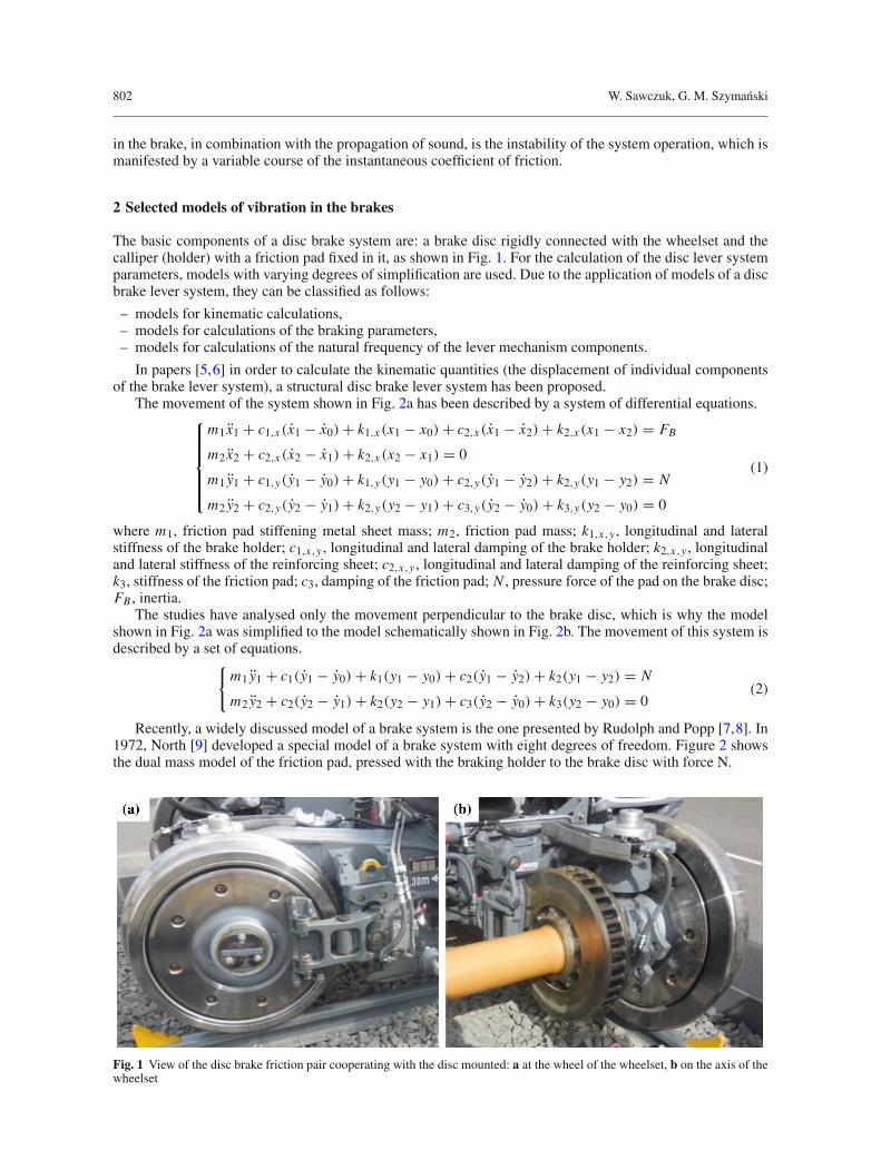
The basic components of a disc brake system are: a brake disc rigidly connected with the wheelset and thecalliper (holder) with a friction pad fixed in it, as shown in Fig. 1. For the calculation of the disc lever systemparameters, models with varying degrees of simplification are used. Due to the application of models of a discbrake lever system, they can be classified as follows:
– models for kinematic calculations,– models for calculations of the braking parameters,– models for calculations of the natural frequency of the lever mechanism components.
In papers [5,6] in order to calculate the kinematic quantities (the displacement of individual componentsof the brake lever system), a structural disc brake lever system has been proposed.
The movement of the system shown in Fig. 2a has been described by a system of differential equations.⎧⎪⎪⎪⎪⎨
⎪⎪⎪⎪⎩
m1 x1 + c1,x (x1 − x0) + k1,x (x1 − x0) + c2,x (x1 − x2) + k2,x (x1 − x2) = FB
m2 x2 + c2,x (x2 − x1) + k2,x (x2 − x1) = 0
m1 y1 + c1,y(y1 − y0) + k1,y(y1 − y0) + c2,y(y1 − y2) + k2,y(y1 − y2) = N
m2 y2 + c2,y(y2 − y1) + k2,y(y2 − y1) + c3,y(y2 − y0) + k3,y(y2 − y0) = 0
(1)
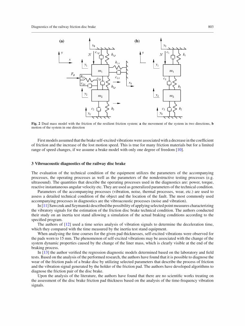
where m1, friction pad stiffening metal sheet mass; m2, friction pad mass; k1,x,y , longitudinal and lateralstiffness of the brake holder; c1,x,y , longitudinal and lateral damping of the brake holder; k2,x,y , longitudinaland lateral stiffness of the reinforcing sheet; c2,x,y , longitudinal and lateral damping of the reinforcing sheet;k3, stiffness of the friction pad; c3, damping of the friction pad; N , pressure force of the pad on the brake disc;FB , inertia.
The studies have analysed only the movement perpendicular to the brake disc, which is why the modelshown in Fig. 2a was simplified to the model schematically shown in Fig. 2b. The movement of this system isdescribed by a set of equations.
{m1 y1 + c1(y1 − y0) + k1(y1 − y0) + c2(y1 − y2) + k2(y1 − y2) = N
m2 y2 + c2(y2 − y1) + k2(y2 − y1) + c3(y2 − y0) + k3(y2 − y0) = 0(2)
Recently, a widely discussed model of a brake system is the one presented by Rudolph and Popp [7,8]. In1972, North [9] developed a special model of a brake system with eight degrees of freedom. Figure 2 showsthe dual mass model of the friction pad, pressed with the braking holder to the brake disc with force N.
Fig. 1 View of the disc brake friction pair cooperating with the disc mounted: a at the wheel of the wheelset, b on the axis of thewheelset
Diagnostics of the railway friction disc brake 803
Fig. 2 Dual mass model with the friction of the resilient friction system: a the movement of the system in two directions, bmotion of the system in one direction
Firstmodels assumed that the brake self-excited vibrationswere associatedwith a decrease in the coefficientof friction and the increase of the lost motion speed. This is true for many friction materials but for a limitedrange of speed changes, if we assume a brake model with only one degree of freedom [10].
3 Vibroacoustic diagnostics of the railway disc brake
The evaluation of the technical condition of the equipment utilizes the parameters of the accompanyingprocesses, the operating processes as well as the parameters of the nondestructive testing processes (e.g.ultrasound). The quantities that describe the operating processes used in the diagnostics are: power, torque,reactive instantaneous angular velocity etc. They are used as generalized parameters of the technical condition.
Parameters of the accompanying processes (vibration, noise, thermal processes, wear, etc.) are used toassess a detailed technical condition of the object and the location of the fault. The most commonly usedaccompanying processes in diagnostics are the vibroacoustic processes (noise and vibration).
In [11] Sawczuk andSzymanski described the possibility of applying selected pointmeasures characterizingthe vibratory signals for the estimation of the friction disc brake technical condition. The authors conductedtheir study on an inertia test stand allowing a simulation of the actual braking conditions according to thespecified program.
The authors of [12] used a time series analysis of vibration signals to determine the deceleration time,which they compared with the time measured by the inertia test stand equipment.
When analysing the time courses for the given pad thicknesses, self-excited vibrations were observed forthe pads worn to 15 mm. The phenomenon of self-excited vibrations may be associated with the change of thesystem dynamic properties caused by the change of the liner mass, which is clearly visible at the end of thebraking process.
In [13] the author verified the regression diagnostic models determined based on the laboratory and fieldtests. Based on the analysis of the performed research, the authors have found that it is possible to diagnose thewear of the friction pads of a brake disc by utilizing selected parameters that describe the process of frictionand the vibration signal generated by the holder of the friction pad. The authors have developed algorithms todiagnose the friction pair of the disc brake.
Upon the analysis of the literature, the authors have found that there are no scientific works treating onthe assessment of the disc brake friction pad thickness based on the analysis of the time-frequency vibrationsignals.
804 W. Sawczuk, G. M. Szymanski
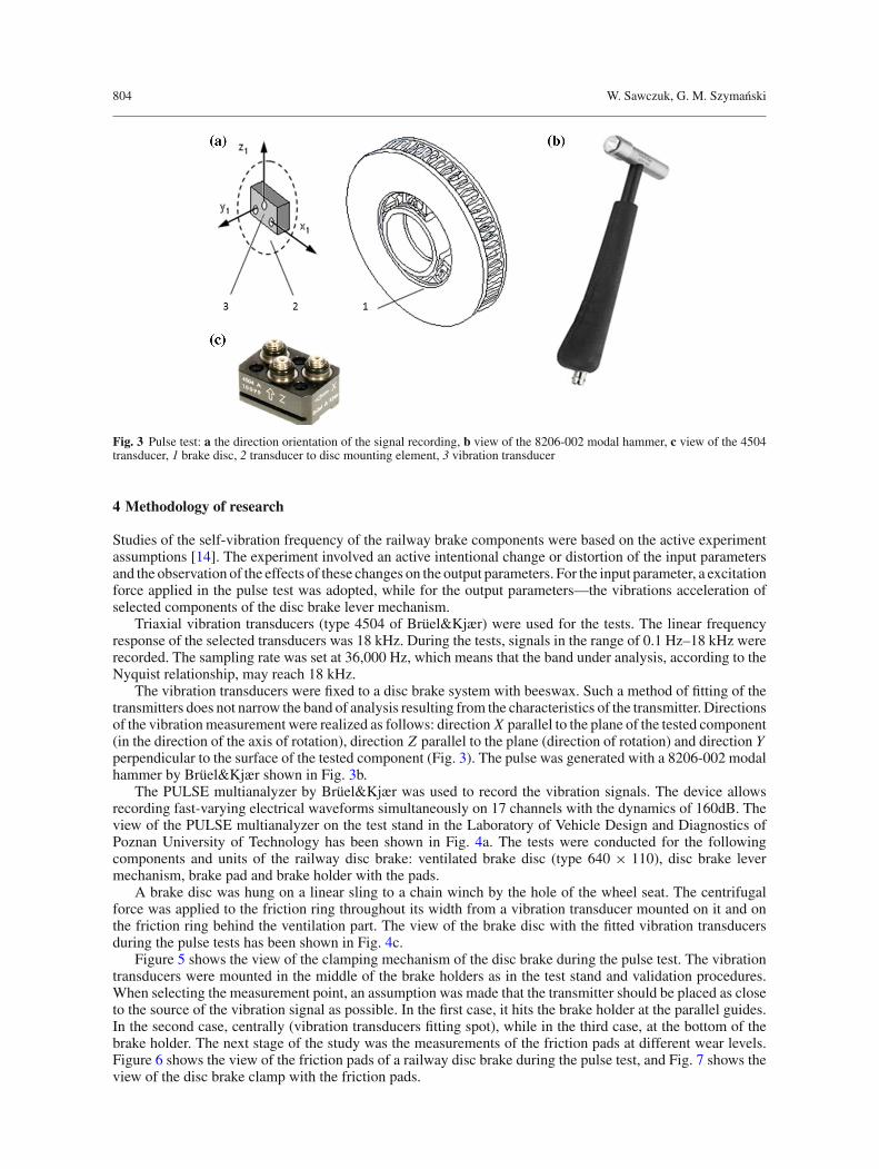
Fig. 3 Pulse test: a the direction orientation of the signal recording, b view of the 8206-002 modal hammer, c view of the 4504transducer, 1 brake disc, 2 transducer to disc mounting element, 3 vibration transducer
4 Methodology of research
Studies of the self-vibration frequency of the railway brake components were based on the active experimentassumptions [14]. The experiment involved an active intentional change or distortion of the input parametersand the observation of the effects of these changes on the output parameters. For the input parameter, a excitationforce applied in the pulse test was adopted, while for the output parameters—the vibrations acceleration ofselected components of the disc brake lever mechanism.
Triaxial vibration transducers (type 4504 of Brüel&Kjær) were used for the tests. The linear frequencyresponse of the selected transducers was 18 kHz. During the tests, signals in the range of 0.1 Hz–18 kHz wererecorded. The sampling rate was set at 36,000 Hz, which means that the band under analysis, according to theNyquist relationship, may reach 18 kHz.
The vibration transducers were fixed to a disc brake system with beeswax. Such a method of fitting of thetransmitters does not narrow the band of analysis resulting from the characteristics of the transmitter. Directionsof the vibrationmeasurement were realized as follows: direction X parallel to the plane of the tested component(in the direction of the axis of rotation), direction Z parallel to the plane (direction of rotation) and direction Yperpendicular to the surface of the tested component (Fig. 3). The pulse was generated with a 8206-002 modalhammer by Brüel&Kjær shown in Fig. 3b.
The PULSE multianalyzer by Brüel&Kjær was used to record the vibration signals. The device allowsrecording fast-varying electrical waveforms simultaneously on 17 channels with the dynamics of 160dB. Theview of the PULSE multianalyzer on the test stand in the Laboratory of Vehicle Design and Diagnostics ofPoznan University of Technology has been shown in Fig. 4a. The tests were conducted for the followingcomponents and units of the railway disc brake: ventilated brake disc (type 640 × 110), disc brake levermechanism, brake pad and brake holder with the pads.
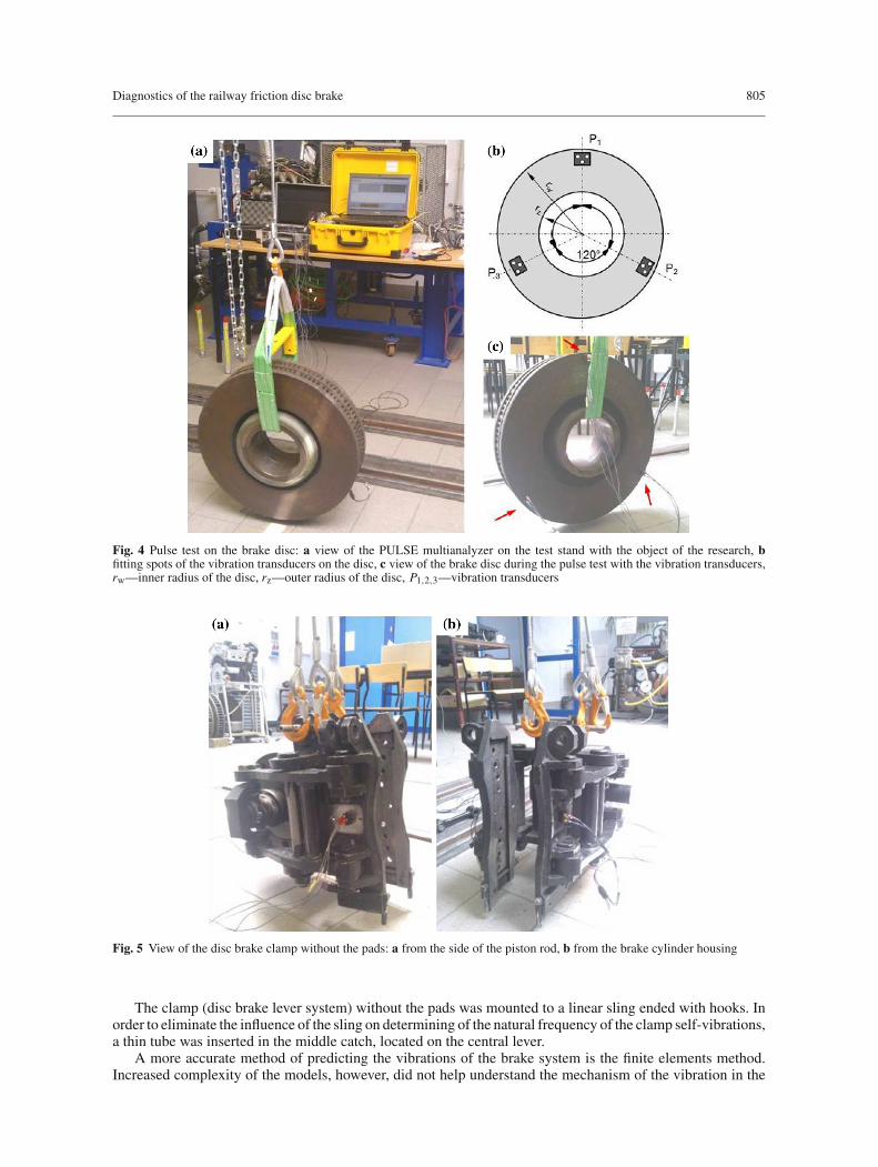
A brake disc was hung on a linear sling to a chain winch by the hole of the wheel seat. The centrifugalforce was applied to the friction ring throughout its width from a vibration transducer mounted on it and onthe friction ring behind the ventilation part. The view of the brake disc with the fitted vibration transducersduring the pulse tests has been shown in Fig. 4c.
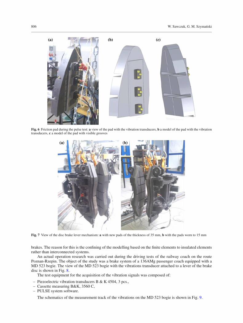
Figure 5 shows the view of the clamping mechanism of the disc brake during the pulse test. The vibrationtransducers were mounted in the middle of the brake holders as in the test stand and validation procedures.When selecting the measurement point, an assumption was made that the transmitter should be placed as closeto the source of the vibration signal as possible. In the first case, it hits the brake holder at the parallel guides.In the second case, centrally (vibration transducers fitting spot), while in the third case, at the bottom of thebrake holder. The next stage of the study was the measurements of the friction pads at different wear levels.Figure 6 shows the view of the friction pads of a railway disc brake during the pulse test, and Fig. 7 shows theview of the disc brake clamp with the friction pads.
Diagnostics of the railway friction disc brake 805
Fig. 4 Pulse test on the brake disc: a view of the PULSE multianalyzer on the test stand with the object of the research, bfitting spots of the vibration transducers on the disc, c view of the brake disc during the pulse test with the vibration transducers,rw—inner radius of the disc, rz—outer radius of the disc, P1,2,3—vibration transducers
Fig. 5 View of the disc brake clamp without the pads: a from the side of the piston rod, b from the brake cylinder housing
The clamp (disc brake lever system) without the pads was mounted to a linear sling ended with hooks. Inorder to eliminate the influence of the sling on determining of the natural frequency of the clamp self-vibrations,a thin tube was inserted in the middle catch, located on the central lever.
A more accurate method of predicting the vibrations of the brake system is the finite elements method.Increased complexity of the models, however, did not help understand the mechanism of the vibration in the
806 W. Sawczuk, G. M. Szymanski
Fig. 6 Friction pad during the pulse test: a view of the pad with the vibration transducers, b a model of the pad with the vibrationtransducers, c a model of the pad with visible grooves
Fig. 7 View of the disc brake lever mechanism: a with new pads of the thickness of 35 mm, b with the pads worn to 15 mm
brakes. The reason for this is the confining of the modelling based on the finite elements to insulated elementsrather than interconnected systems.
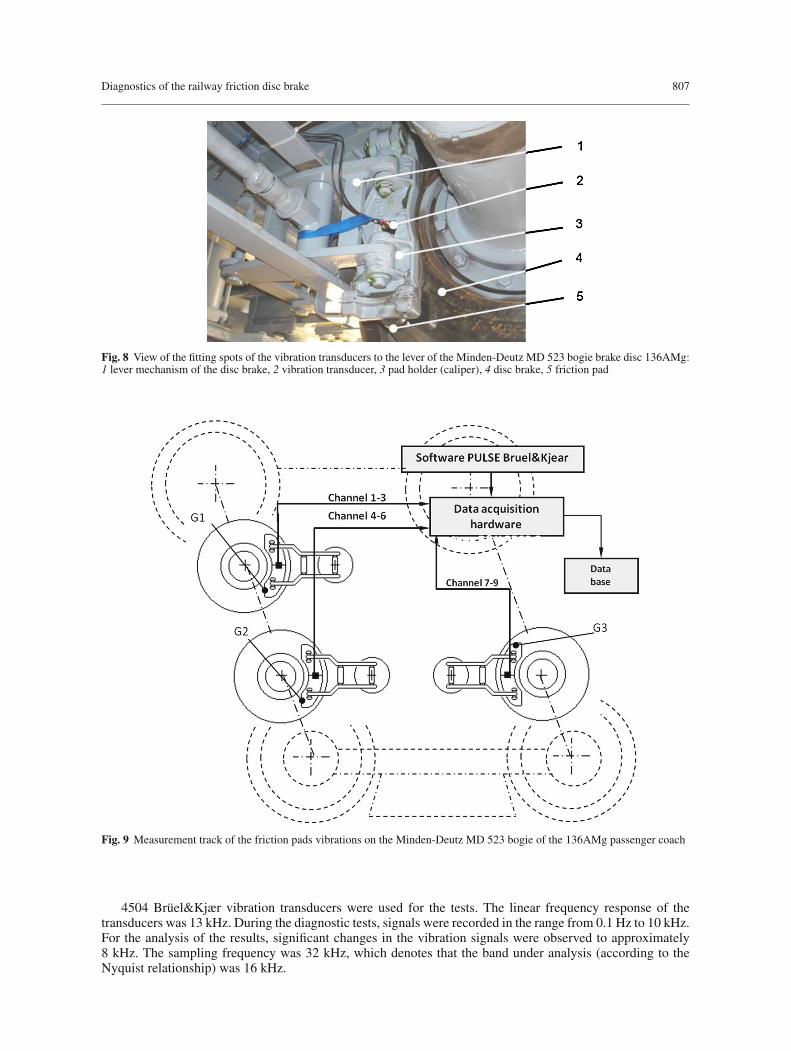
An actual operation research was carried out during the driving tests of the railway coach on the routePoznan-Rzepin. The object of the study was a brake system of a 136AMg passenger coach equipped with aMD 523 bogie. The view of the MD 523 bogie with the vibrations transducer attached to a lever of the brakedisc is shown in Fig. 8.
The test equipment for the acquisition of the vibration signals was composed of:
– Piezoelectric vibration transducers B & K 4504, 3 pcs.,– Cassette measuring B&K, 3560 C,– PULSE system software.
The schematics of the measurement track of the vibrations on the MD 523 bogie is shown in Fig. 9.
Diagnostics of the railway friction disc brake 807
Fig. 8 View of the fitting spots of the vibration transducers to the lever of the Minden-Deutz MD 523 bogie brake disc 136AMg:1 lever mechanism of the disc brake, 2 vibration transducer, 3 pad holder (caliper), 4 disc brake, 5 friction pad
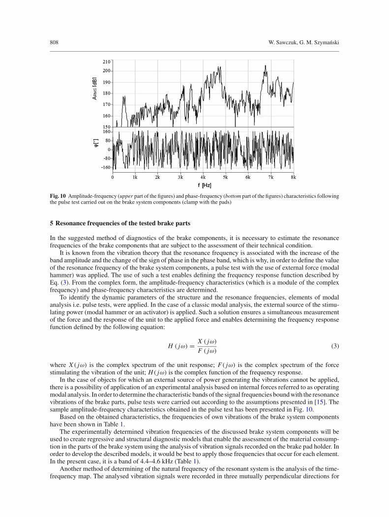
Fig. 9 Measurement track of the friction pads vibrations on the Minden-Deutz MD 523 bogie of the 136AMg passenger coach
4504 Brüel&Kjær vibration transducers were used for the tests. The linear frequency response of thetransducers was 13 kHz. During the diagnostic tests, signals were recorded in the range from 0.1 Hz to 10 kHz.For the analysis of the results, significant changes in the vibration signals were observed to approximately8 kHz. The sampling frequency was 32 kHz, which denotes that the band under analysis (according to theNyquist relationship) was 16 kHz.
808 W. Sawczuk, G. M. Szymanski
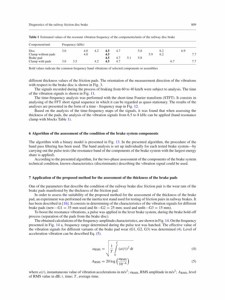
Fig. 10 Amplitude-frequency (upper part of the figures) and phase-frequency (bottom part of the figures) characteristics followingthe pulse test carried out on the brake system components (clamp with the pads)
5 Resonance frequencies of the tested brake parts
In the suggested method of diagnostics of the brake components, it is necessary to estimate the resonancefrequencies of the brake components that are subject to the assessment of their technical condition.
It is known from the vibration theory that the resonance frequency is associated with the increase of theband amplitude and the change of the sign of phase in the phase band, which is why, in order to define the valueof the resonance frequency of the brake system components, a pulse test with the use of external force (modalhammer) was applied. The use of such a test enables defining the frequency response function described byEq. (3). From the complex form, the amplitude-frequency characteristics (which is a module of the complexfrequency) and phase-frequency characteristics are determined.
To identify the dynamic parameters of the structure and the resonance frequencies, elements of modalanalysis i.e. pulse tests, were applied. In the case of a classic modal analysis, the external source of the stimu-lating power (modal hammer or an activator) is applied. Such a solution ensures a simultaneous measurementof the force and the response of the unit to the applied force and enables determining the frequency responsefunction defined by the following equation:
H ( jω) = X ( jω)
F ( jω)(3)
where X ( jω) is the complex spectrum of the unit response; F( jω) is the complex spectrum of the forcestimulating the vibration of the unit; H( jω) is the complex function of the frequency response.
In the case of objects for which an external source of power generating the vibrations cannot be applied,there is a possibility of application of an experimental analysis based on internal forces referred to as operatingmodal analysis. In order to determine the characteristic bands of the signal frequencies boundwith the resonancevibrations of the brake parts, pulse tests were carried out according to the assumptions presented in [15]. Thesample amplitude-frequency characteristics obtained in the pulse test has been presented in Fig. 10.
Based on the obtained characteristics, the frequencies of own vibrations of the brake system componentshave been shown in Table 1.
The experimentally determined vibration frequencies of the discussed brake system components will beused to create regressive and structural diagnostic models that enable the assessment of the material consump-tion in the parts of the brake system using the analysis of vibration signals recorded on the brake pad holder. Inorder to develop the described models, it would be best to apply those frequencies that occur for each element.In the present case, it is a band of 4.4–4.6 kHz (Table 1).
Another method of determining of the natural frequency of the resonant system is the analysis of the time-frequency map. The analysed vibration signals were recorded in three mutually perpendicular directions for
Diagnostics of the railway friction disc brake 809
Table 1 Estimated values of the resonant vibration frequency of the components/units of the railway disc brake
Component/unit Frequency (kHz)
Disc 3.0 4.0 4.2 4.5 4.7 5.8 6.2 6.9Clamp without pads 4.0 4.5 5.9 6.2 7.7Brake pad 4.5 4.7 5.1 5.8Clamp with pads 3.0 3.5 4.2 4.5 4.7 6.7 7.7
Bold values indicate the common frequency band vibrations of selected components or assemblies
different thickness values of the friction pads. The orientation of the measurement direction of the vibrationswith respect to the brake disc is shown in Fig. 3.
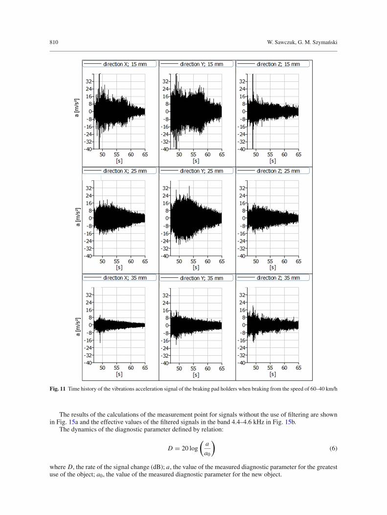
The signals recorded during the process of braking from 60 to 40 km/h were subject to analysis. The timeof the vibration signals is shown in Fig. 11.
The time-frequency analysis was performed with the short-time Fourier transform (STFT). It consists inanalysing of the FFT short signal sequence in which it can be regarded as quasi-stationary. The results of theanalyses are presented in the form of a time - frequency map in Fig. 12.
Based on the analysis of the time-frequency maps of the signals, it was found that when assessing thethickness of the pads, the analysis of the vibration signals from 6.5 to 8 kHz can be applied (band resonanceclamp with blocks Table 1).
6 Algorithm of the assessment of the condition of the brake system components
The algorithm with a binary model is presented in Fig. 13. In the presented algorithm, the procedure of theband pass filtering has been used. The band analysis is set up individually for each tested brake system—bycarrying out the pulse tests (the resonance band of the components of the brake system with the largest energyshare is applied).
According to the presented algorithm, for the two-phase assessment of the components of the brake systemtechnical condition, known characteristics (discriminants) describing the vibration signal could be used.
7 Application of the proposed method for the assessment of the thickness of the brake pads
One of the parameters that describe the condition of the railway brake disc friction pair is the wear rate of thebrake pads manifested by the thickness of the friction pad.
In order to assess the suitability of the proposed method for the assessment of the thickness of the brakepad, an experiment was performed on the inertia test stand used for testing of friction pairs in railway brakes. Ithas been described in [16]. It consists in determining of the characteristics of the vibration signals for differentbrake pads (new—G1 = 35 mm used and fit—G2 = 25 mm; used and unfit—G3 = 15 mm).
To boost the resonance vibrations, a pulse was applied in the lever brake system, during the brake hold-offprocess (separation of the pads from the brake disc).
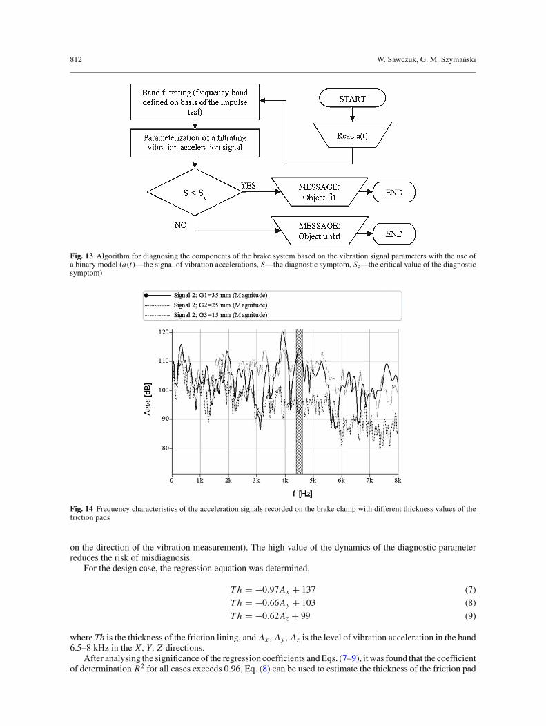
The obtained calculations of the frequency-amplitude characteristics, are shown inFig. 14.On the frequencypresented in Fig. 14 a, frequency range determined during the pulse test was hatched. The effective value ofthe vibration signals for different variants of the brake pad wear (G1, G2, G3) was determined (4). Level ofacceleration vibration can be described Eq. (5).
aRMS =
√√√√√
1
T
T∫
0
(a(t))2 dt (4)
ARMS = 20 log(aRMS
10−6
)(5)
where a(t), instantaneous value of vibration accelerations in m/s2; aRMS, RMS amplitude in m/s2; ARMS, levelof RMS value in dB; t , time; T , average time.
810 W. Sawczuk, G. M. Szymanski
Fig. 11 Time history of the vibrations acceleration signal of the braking pad holders when braking from the speed of 60–40 km/h
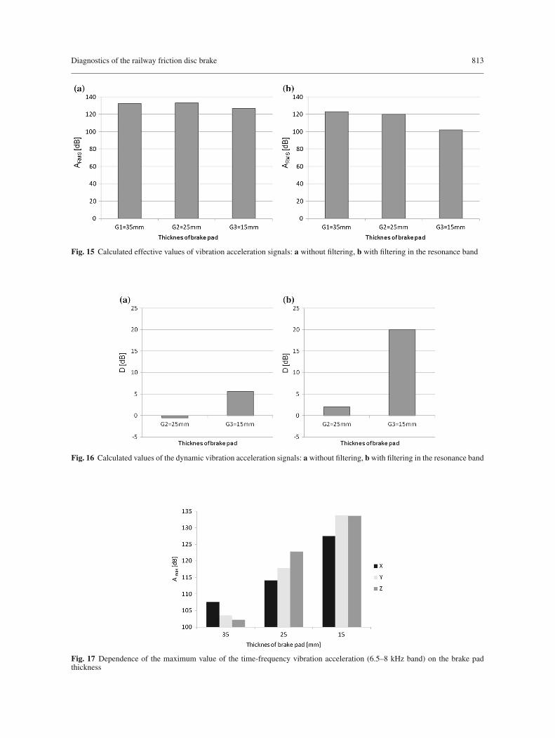
The results of the calculations of the measurement point for signals without the use of filtering are shownin Fig. 15a and the effective values of the filtered signals in the band 4.4–4.6 kHz in Fig. 15b.
The dynamics of the diagnostic parameter defined by relation:
D = 20 log
(a
a0
)
(6)
where D, the rate of the signal change (dB); a, the value of the measured diagnostic parameter for the greatestuse of the object; a0, the value of the measured diagnostic parameter for the new object.
Diagnostics of the railway friction disc brake 811
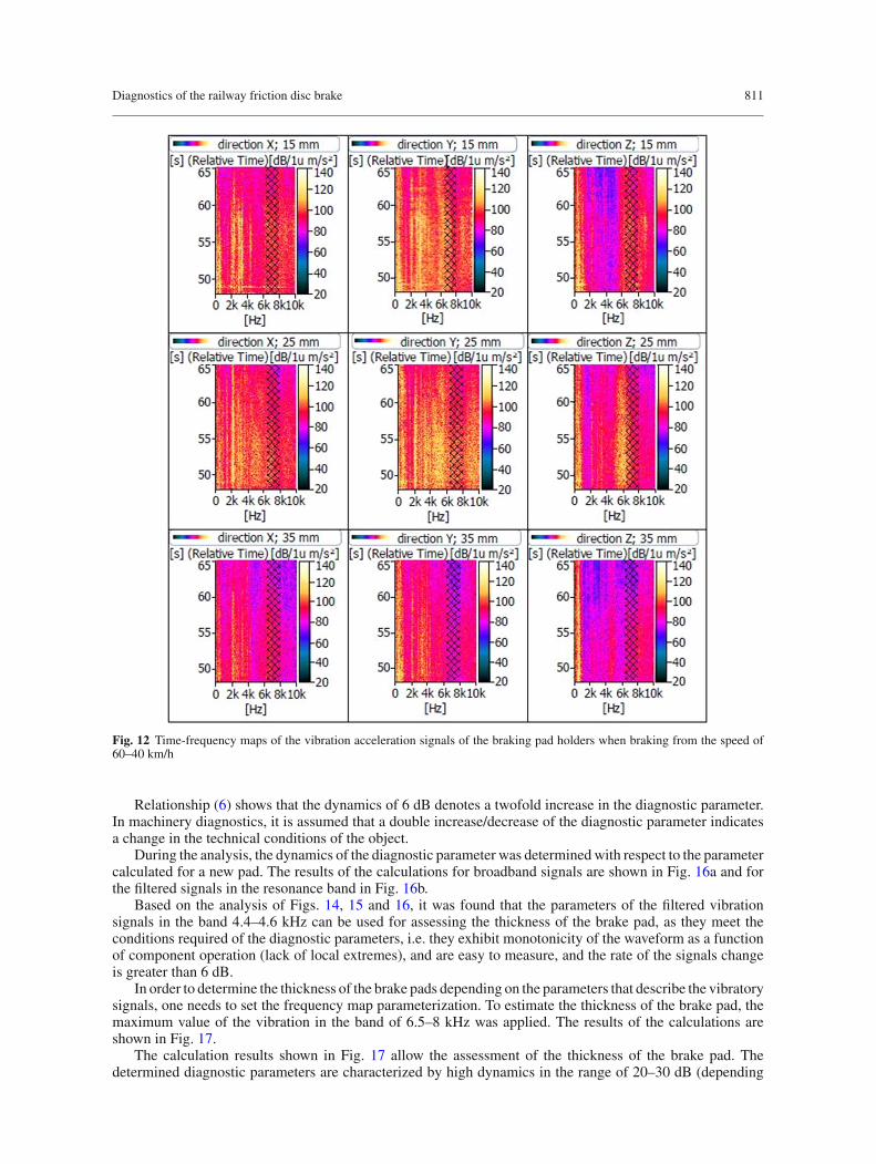
Fig. 12 Time-frequency maps of the vibration acceleration signals of the braking pad holders when braking from the speed of60–40 km/h
Relationship (6) shows that the dynamics of 6 dB denotes a twofold increase in the diagnostic parameter.In machinery diagnostics, it is assumed that a double increase/decrease of the diagnostic parameter indicatesa change in the technical conditions of the object.
During the analysis, the dynamics of the diagnostic parameter was determinedwith respect to the parametercalculated for a new pad. The results of the calculations for broadband signals are shown in Fig. 16a and forthe filtered signals in the resonance band in Fig. 16b.
Based on the analysis of Figs. 14, 15 and 16, it was found that the parameters of the filtered vibrationsignals in the band 4.4–4.6 kHz can be used for assessing the thickness of the brake pad, as they meet theconditions required of the diagnostic parameters, i.e. they exhibit monotonicity of the waveform as a functionof component operation (lack of local extremes), and are easy to measure, and the rate of the signals changeis greater than 6 dB.
In order to determine the thickness of the brake pads depending on the parameters that describe the vibratorysignals, one needs to set the frequency map parameterization. To estimate the thickness of the brake pad, themaximum value of the vibration in the band of 6.5–8 kHz was applied. The results of the calculations areshown in Fig. 17.
The calculation results shown in Fig. 17 allow the assessment of the thickness of the brake pad. Thedetermined diagnostic parameters are characterized by high dynamics in the range of 20–30 dB (depending
812 W. Sawczuk, G. M. Szymanski
Fig. 13 Algorithm for diagnosing the components of the brake system based on the vibration signal parameters with the use ofa binary model (a(t)—the signal of vibration accelerations, S—the diagnostic symptom, Sc—the critical value of the diagnosticsymptom)
Fig. 14 Frequency characteristics of the acceleration signals recorded on the brake clamp with different thickness values of thefriction pads
on the direction of the vibration measurement). The high value of the dynamics of the diagnostic parameterreduces the risk of misdiagnosis.
For the design case, the regression equation was determined.
Th = −0.97Ax + 137 (7)
Th = −0.66Ay + 103 (8)
Th = −0.62Az + 99 (9)
where Th is the thickness of the friction lining, and Ax , Ay, Az is the level of vibration acceleration in the band6.5–8 kHz in the X, Y, Z directions.
After analysing the significance of the regression coefficients andEqs. (7–9), itwas found that the coefficientof determination R2 for all cases exceeds 0.96, Eq. (8) can be used to estimate the thickness of the friction pad
Diagnostics of the railway friction disc brake 813
Fig. 15 Calculated effective values of vibration acceleration signals: a without filtering, b with filtering in the resonance band
Fig. 16 Calculated values of the dynamic vibration acceleration signals: a without filtering, bwith filtering in the resonance band
Fig. 17 Dependence of the maximum value of the time-frequency vibration acceleration (6.5–8 kHz band) on the brake padthickness
814 W. Sawczuk, G. M. Szymanski
and Eqs. (7) and (9) should be rejected because the regression coefficients determined by these equations arestatistically insignificant.
In the present case, the statistical regression analysis is indicative because the determined regressioncoefficients are subject to significant errors resulting from the small sample size (3 points).
8 Conclusions
The paper presented a method of evaluation of the brake pad conditions based on the resonance vibrationsmeasured on the brake block holder. Based on the research, it was found that the vibration signal filtrationin the resonance band increases the dynamics of the diagnostic parameter by approximately 14 dB (from 5.6to 20 dB). Taking a criterion into account, in which it is assumed that the change of the object’s technicalcondition is indicated by the increase of a diagnostic symptom by 6 dB, it can be concluded that the diagnosticmodel without the use of signal filtration does not guarantee the distinction of the technical condition of thefriction components in the tested disc brake, while the signal analysis with the filtration in the band 4.4–4.6 kHz enables a clear evaluation of the technical condition of the tested components. The disadvantage ofthe described method is that the pulse test should be performed for each brake type in order to determine theresonant frequencies of the tested systems.
The paper also presented the possibility of using the vibration signal to assess the condition of the frictiondisc brake. After analysing the time-frequency vibration acceleration signals, it was found that it is possible todetermine the wear of the friction pads based on the maximum value from the time-frequency map of vibrationacceleration in the band of 6.5–8 kHz under actual on-track operation. The best direction in the discussed caseis the Y direction of the measurement of the vibration acceleration, which is perpendicular to the surface of thefriction disc. The determined diagnostic parameters for the signals recorded in this direction are characterizedby the dynamics of approx. 30 dB.
Acknowledgements The project has been financed by the National Centre for Research and Development, program LIDER V,Contract No. LIDER/022/359/L-5/13/NCBR/2014.
Open Access This article is distributed under the terms of the Creative Commons Attribution 4.0 International License (http://creativecommons.org/licenses/by/4.0/), which permits unrestricted use, distribution, and reproduction in any medium, providedyou give appropriate credit to the original author(s) and the source, provide a link to the Creative Commons license, and indicateif changes were made.
References
1. Sawczuk, W., Szymanski, G.M.: Application of analysis of resonance vibration for the diagnosis of a pair of friction of therailway disc brake page 437-448 in the Dynamical Systems Mathematical and Numerical Approaches. In: Awrejcewicz J.,KazmierczakM.,Mrozowski J., Olejnik P. (eds.) 13th International ConferenceDynamical SystemsTheory andApplications,December 7–10, 2015, Łódz, Poland
2. Kinkaid, N.M., O’Reilly, O.M., Papadopoulos, P.: Automotive disc brake squeal. J. Sound Vib. 267, 105–166 (2003).Department of Mechanical Engineering, University of California, Berkeley, USA
3. Kruse, S., Tiedemann, M., Zeumer, B., Reuss, P., Hetzler, H., Hoffmann, N.: The influence of joints of friction inducedvibration in brake squeal. J. Sound Vib. 340, 239–252 (2015)
4. Thompson, J.K., Brake N.V.H.: Testing and Measurements. SAE International, pp. 1–20 (2011)5. Kedziołka, T., Kowalski, S., Smolarski, D.: Comparative analysis of the sensitivity of the brake lever railway. Rail vehicles
1/2011 (in Polish)6. Nowicki, J.: Simulations train braking performance, XIV Scientific Conference Rail Vehicles 2000, Krakow, Arkanow, 9–13
October 2000, t. 2, pp. 139–146 (in Polish)7. Rudolph, M., Popp, K.: Brake squeal. In: Popp, K. (ed.) Detection, Utilization and Avoidance of Nonlinear Dynamical
Effects in Engineering Applications: Final Report of a Joint Research Project Sponsored by the German Federal Ministry ofEducation and Research, Shaker, Aachen, pp. 197–225 (2001)
8. Rudolph, M., Popp, K.: Friction induced brake vibrations. In: CD-ROM Proceedings of DETC’01, DETC2001/VIB-21509,ASME, Pittsburgh, PA, pp. 1–10 (2001)
9. North, M.R: Disc brake squeal—a theoretical model. Technical Report 1972/5, Motor Industry Research Association, War-wickshire, England (1972)
10. Scieszka, S.F.: Friction brakes. Issues of materials, structural and tribological Publishing Gliwice-Radom, p. 15 (1998) (inPolish)
11. Sawczuk, W., Szymanski, G.M.: The use of the vibration signal to the evaluation of the technical condition of the frictionbrake station.Materials 28mezinarodni vedecka konferenceDIAGOR2009, CzechyRožnov podRadhoštem, 27–28.01.2009Technicka Diagnostika, z 1 Rocnik XVIII 2009, p. 34—abstract, paper on CD, pp. 271–275 (2009)
Diagnostics of the railway friction disc brake 815
12. Sawczuk, W., Szymanski, G.M.: Application of selected time and amplitude characteristics of vibration signal to diagnoserailway disc brake. Monograph, Gdansk (2010)
13. Sawczuk, W.: Research disc brake of a rail vehicle in the aspect of possibilities to diagnose. Ph.D. Thesis Poznan Universityof Technology, Poznan (2010) (in Polish)
14. Junior, M.T., Gerges, S.N.Y., Jordan, R.: Analysis of brake squeal noise using finite element method: a parametric study.Appl. Acoust. 69, 147–162 (2008)
15. Sawczuk, W., Szymanski, G.M.: Application of the test pulse to estimate the resonant frequency of selected elements of therail brake, Logistics 6/2014 (in Polish)
16. Szymanski, G., Sawczuk,W.: Assessing thickness of friction pad of railway disk brake on the basis of time-frequency analysisof vibration signals. Logistyka (4), CD–CD (2010) (in Polish)