Embed Size (px)
Citation preview
DIAGNOSIS AND MONITORING OF THE PMSM USING THE ANALYTICAL MODEL METHOD
Virginia Ivanov Maria Brojboiu Sergiu Ivanov
University of Craiova Faculty of Electrical Engineering
107 Decebal Blv., 200440, Craiova, Romania [email protected], [email protected], [email protected]
KEYWORDS Diagnosis, PMSM, fault operation, short circuited. ABSTRACT
The paper applies the diagnosis method based on the analytic model by investigating the output waveforms of the currents, torque and speed specific to a PMSM driving system. Several faults are simulated: open phase, entire phase short circuit in two situations (with and without current measurement, short circuit before and after current sensor respectively) and current sensor fault (no reaction). Thanks to the described model, the method based on analytic models can be applied and the system behavior can be compared with the results of the mathematical model which reproduces the system in normal operation. For all types of faults, more or less important oscillations of the currents and output torque are noticed. The consequences are corresponding, more or less severe and can lead to major damages. INTRODUCTION
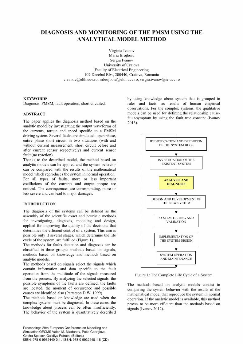
The diagnosis of the systems can be defined as the assembly of the scientific exact and heuristic methods for investigating, diagnosis, modeling and design, applied for improving the quality of the decisions that determines the efficient control of a system. This aim is possible only if several stages, which determine the life cycle of the system, are fulfilled (Figure 1). The methods for faults detection and diagnosis can be classified in three groups: methods based on signals, methods based on knowledge and methods based on analytic models. The methods based on signals select the signals which contain information and data specific to the fault operation from the multitude of the signals measured from the process. By analyzing the selected signals, the possible symptoms of the faults are defined, the faults are located, the moment of occurrence and possible causes are identified also (Patterson D.W. 1999). The methods based on knowledge are used when the complex systems must be diagnosed. In these cases, the knowledge about process can be often insufficiently. The behavior of the system is quantitatively described
by using knowledge about system that is grouped in rules and facts, as results of human empirical observations. For the complex systems, the qualitative models can be used for defining the relationship cause-fault-symptom by using the fault tree concept (Ivanov 2013).
Figure 1: The Complete Life Cycle of a System The methods based on analytic models consist in comparing the system behavior with the results of the mathematical model that reproduce the system in normal operation. If the analytic model is available, this method proves to be more efficient than the methods based on signals (Ivanov 2012).
SYSTEM OPERATION AND MAINTENANCE
SYSTEM TESTING AND VALIDATION
DESIGN AND DEVELOPMENT OF THE NEW SYSTEM
INVESTIGATION OF THE EXISTENT SYSTEM
IMPLEMENTATION OF THE SYSTEM DESIGN
ANALYSIS AND DIAGNOSIS
IDENTIFICATION AND DEFINITION OF THE SYSTEM BUGS
Proceedings 29th European Conference on Modelling and Simulation ©ECMS Valeri M. Mladenov, Petia Georgieva, Grisha Spasov, Galidiya Petrova (Editors) ISBN: 978-0-9932440-0-1 / ISBN: 978-0-9932440-1-8 (CD)

For achieving the diagnosis, the system model must be developed in order to analyze the fault propagation in different monitoring locations. By using high energy permanent magnets for machines excitation, superior performances motors can be obtained. Mainly, in the present, two types of permanent magnets machines are studied and largely used: the synchronous one (PMSM) and the brushless DC one (BLDCM). The two have important advantages: high efficiency, very clear and well known control strategies, no looses in the rotor side, so only the stator must be cooled, high reliability, long life, easy maintenance, high power density which leads to reduced weight and size (Vinson 2012). There still are several disadvantages: the price is pretty high due to the permanent magnets, the demagnetization can occur if the motors operate at high temperature, due to the limited de-fluxing possibilities (risk for the permanent magnets), the constant power range is limited. In addition, the PMSM, compared with the BLDCM has the disadvantage that requires precise absolute position transducer. In the current applications, the motors are always supplied by inverters. Some faults of them can lead to severe damages to motors. An example is the two phases short circuit. This means the short circuit of two motor phases. If the machine continues the rotate, due to the permanent magnets on the rotor, back emf are still induced. These are closed on the two short circuited phases which leads to quite important currents (analog to the two phases short circuit on a generator ends). The open circuit faults are not very dangerous concerning the motor stability. In the absence of a proper control, this fault can lead to severe consequences. In this case, the high back emf resulted if the motor continues to rotate can determine the increasing of the DC bus voltage if a proper control is not performed (bidirectional rectifier or braking resistor) (Meinguet 2011). The stator faults are generally related to the insulation. A partial short circuit of several turns is difficultly detected and almost impossible to be eliminated. There are several techniques for faults detection, the most of them based on the stator voltages and currents analysis. In order to prevent the faults occurrence and to ensure the optimum maintenance, the PMSM can be efficiently monitored. The paper proposes a method of diagnosis for many types of faults:
- a broken phase (i.e a phase in open circuit), - a phase totally or partially short circuited - the loss of a current sensor.
The behavior when the first two faults occur will be detailed in the paper. In order to be able to simulate the mentioned faults, the machines model will be expressed not in the classic Park reference frame, (d, q), but in terms of instantaneous phase variables.
MOTORS MODELS
The paper will present the approach for building the different models and their inter-connection. The models of the motors must have as inputs the phase voltages delivered by the inverter, the mechanical speed and position of the rotor. The outputs must be the phase currents and the electromagnetic torque. The mechanical parameters (rotor inertia, friction) are included in the model of the mechanical load (not presented in the paper) which is then driven by the electromagnetic torque. In the following equations, significance of the notations is: ua, ub, uc – phase voltages; ia, ib, ic – phase currents; Rs – phase resistance; Ls – phase inductance; Ms – mutual inductance between two phases; KT – torque constant; P – number of pairs of poles; θm – angular position of the rotor. Three phase classic PMSM with separate feeding of the phases
The first architecture which is considered is corresponding to a classic PM synchronous motor with separated feeding of the phases, each phase being fed by an H bridge. (Figure 2).
Figure 2: Three Phase Machine with Separated Phases In this case the electrical equations are:
0 00 00 0
sin2sin3
4sin3
a s a s s s a
b s b s s s b
c s c s s s c
m
T m m
m
u R i L M M idu R i M L M idt
u R i M M L i
P
K P
P
= + +
− θ π + θ − θ −
π − θ −
�
and the electromagnetic torque expression is: 2sin sin3
4sin .3
em T a m b m
c m
T K i P i P
i P
π = − θ + θ − +
π + θ −
.
In these equations, rotor zero position is considered to correspond to the maximum coupling between phase “a”and the rotor, so that the flux induced in the phase “a”by the magnets, Φaf is maximum for θm = 0 and, assuming a sinusoidal coupling, can be expressed as follows:
cosaf M mPΦ = Φ θ .
Consequently, the back emf induced by the magnets in phase “a” is equal to:
sin sina M m m T m me P P K P= − Φ θ θ = − θ θ� � ,
with T MK P= Φ .With this model, the following faults can be simulated: •one phase in open circuit is simulated by imposing
simultaneously its current value and the corresponding /di dt to zero;
•one phase in short circuit is simulated by imposing to zero the corresponding feeding voltage;
• fault of a current sensor is simulated by imposing to zero the feedback value of the current on one phase (phase “a”).
Classic PMSM with star connected windings and insulated neutral
If the machine phases is star connected with insulated neutral, it must be fed by a three phase inverter (Figure 3).
Figure 3: Three Phase Machine Star Connected
Since in this case, 0a b ci i i+ + = the matrix
s s s
s s s
s s s
L M MM L MM M L
can be replaced by 0
0
0
0 00 00 0
LL
L
,
with ( )0 0s s sL L M M= − < , the cyclical inductance. The input variables controlled by the inverter are the line voltages ua-ub, ub-uc and uc-ua. Their sum being equal to zero, only two of them are independent, so the motor equations can be written as
( )
( )
0 0
0 02 2
2sin sin3
.4sin sin3
a b s s a a
a c s s b b
m m
T m
m m
u u R R i L L idu u R R i L L idt
P PK
P P
− − − = + + −
π − θ + θ − + θ
π − θ + θ −
�
With c a bi i i= − − , the electromagnetic torque is obtained with the same expression as the previous model. With this model, the fault that can be simulated is the current sensor failure as for the previous model. Writing the equations in terms of line voltages makes possible the simulation of a phase partial short circuit. This facility is not yet implemented in the presented models. THE SIMULINK MOTORS MODELS
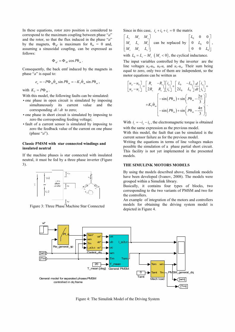
By using the models described above, Simulink models have been developed (Ivanov, 2008). The models were grouped within a Simulink library. Basically, it contains four types of blocks, two corresponding to the two variants of PMSM and two for the controllers. An example of integration of the motors and controllers models for obtaining the driving system model is depicted in Figure 4.
Figure 4: The Simulink Model of the Driving System
General model for separated phases PMSM controlled in dq frame
[wm]
w*
[Tm]
[Tm]
0Tamt
20T_mean [deg]
PI_e
Rw_general_sp
PMSM_general_dq
Tem
Tamt
wm
Tm
Mech load [wm]
ua
ub
uc
wm
Tm
T_mean
i_a,b,c
Tem
General PMSM
Tem*wm
Tm
i_a,b,c
ua*
ub*
uc*
Control_dq
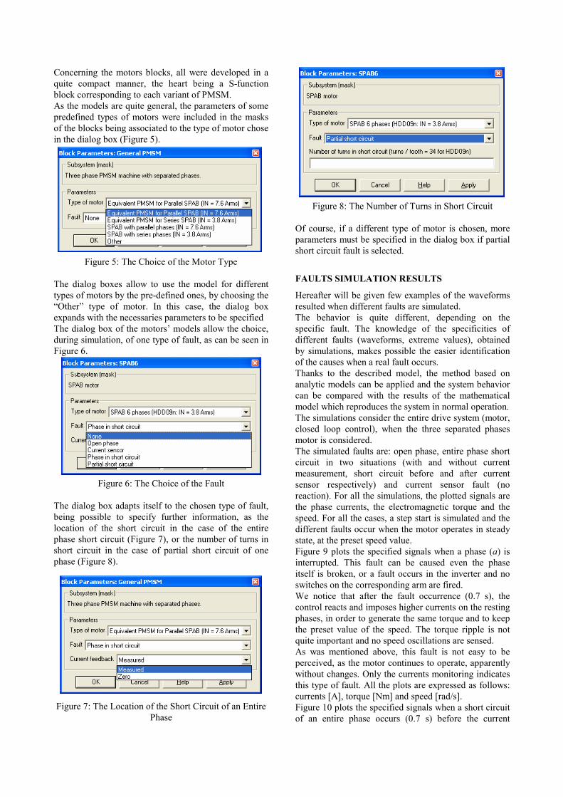
Concerning the motors blocks, all were developed in a quite compact manner, the heart being a S-function block corresponding to each variant of PMSM. As the models are quite general, the parameters of some predefined types of motors were included in the masks of the blocks being associated to the type of motor chose in the dialog box (Figure 5).
Figure 5: The Choice of the Motor Type The dialog boxes allow to use the model for different types of motors by the pre-defined ones, by choosing the “Other” type of motor. In this case, the dialog box expands with the necessaries parameters to be specified The dialog box of the motors’ models allow the choice, during simulation, of one type of fault, as can be seen in Figure 6.
Figure 6: The Choice of the Fault The dialog box adapts itself to the chosen type of fault, being possible to specify further information, as the location of the short circuit in the case of the entire phase short circuit (Figure 7), or the number of turns in short circuit in the case of partial short circuit of one phase (Figure 8).
Figure 7: The Location of the Short Circuit of an Entire Phase
Figure 8: The Number of Turns in Short Circuit Of course, if a different type of motor is chosen, more parameters must be specified in the dialog box if partial short circuit fault is selected.
FAULTS SIMULATION RESULTS
Hereafter will be given few examples of the waveforms resulted when different faults are simulated. The behavior is quite different, depending on the specific fault. The knowledge of the specificities of different faults (waveforms, extreme values), obtained by simulations, makes possible the easier identification of the causes when a real fault occurs. Thanks to the described model, the method based on analytic models can be applied and the system behavior can be compared with the results of the mathematical model which reproduces the system in normal operation. The simulations consider the entire drive system (motor, closed loop control), when the three separated phases motor is considered. The simulated faults are: open phase, entire phase short circuit in two situations (with and without current measurement, short circuit before and after current sensor respectively) and current sensor fault (no reaction). For all the simulations, the plotted signals are the phase currents, the electromagnetic torque and the speed. For all the cases, a step start is simulated and the different faults occur when the motor operates in steady state, at the preset speed value. Figure 9 plots the specified signals when a phase (a) is interrupted. This fault can be caused even the phase itself is broken, or a fault occurs in the inverter and no switches on the corresponding arm are fired. We notice that after the fault occurrence (0.7 s), the control reacts and imposes higher currents on the resting phases, in order to generate the same torque and to keep the preset value of the speed. The torque ripple is not quite important and no speed oscillations are sensed. As was mentioned above, this fault is not easy to be perceived, as the motor continues to operate, apparently without changes. Only the currents monitoring indicates this type of fault. All the plots are expressed as follows: currents [A], torque [Nm] and speed [rad/s]. Figure 10 plots the specified signals when a short circuit of an entire phase occurs (0.7 s) before the current

sensor. In this case, the current sensor delivers the value of the phase current.
Figure 9: Phase Currents [A], Torque [Nm] and Speed [rad/s] when a Phase is Interrupted
Figure 10: Short Circuit with Current Measurement
The fault is quite severe in what concerns the currents values (the most severe of the simulated situations). All the three currents have almost the same phase and consequently, the electromagnetic torque gets some ripple. Due to the motor inertia, this ripple is not propagated to the speed. The fault is quite dangerous because the huge currents on all the phases determine important heating and shortly motor damage. If the phase short circuit occurs after the current sensor, its indication will be zero, as the phase is broken. But the effects are quite different, as it can be seen in Figure 11.
Figure 11: Short Circuit without Current Measurement The currents in the resting phases increase significantly, but not so much as in previous case. They are still more than double the rated current. Contrary, the torque ripple becomes quite important (the peak to peak amplitude is more than double rated torque). Consequently, speed ripple occurs too. This fault is the one which affects most the overall behavior of the drive. The third fault which implies zero current reaction on a phase is the defect of the sensor itself. The results of this faults are plotted in Figure 12. There is no increasing of the currents, because in fact all the three currents continues to flow in the phases, only the information on one of them is false. Cause of this, the coordination transformations of the vector controlled currents components are affected and consequently, the currents waveforms on all the phases. This determines unexpected high ripple of the generated torque, even a

little bigger than a phase short circuit with measured current (case 2). The effects on the speed are, as in the mentioned case, not visible.
Figure 12: Current Sensor in Fault CONCLUSIONS
The paper describes the diagnosis method based on the analytic model by investigating the output waveforms of the currents, torque and speed, specific to a PMSM driving system in normal operation, as well as when different faults occur. The developed Simulink model was used for analyzing the influences and consequences of several faults: open phase, entire phase short circuit and current sensor fault (no reaction) on the system drive operation. The simulation results are very useful for identifying the cause of a failure, by analyzing the output waveforms which present more or less significant oscillations of the electric or mechanic variables. REFERENCES
Ivanov Virginia, Brojboiu Maria, Ivanov S. 2013. “Experimental System for Monitoring and Diagnosis of a Static Power Converter”, Advances in Electrical and Computer Engineering, Vol.13, No.2, 2013, pp. 113-120.
Ivanov Virginia, Brojboiu Maria, Ivanov S. 2012. “Diagnosis System for Power Rectifiers Using the Tree of Faults Method”, Annals of the University of Craiova, Series Electrical Engineering, nr.36, 2012, pp. 350-354.
Ivanov Sergiu, Defosse Vincent, Labrique Francis, Sente Paul. 2008. “Simulink Library for Simulation of the Permanent
Magnets Synchronous Machine Drive”. In Proceedings of 22nd European Conference on Modelling and Simulation, Nicosia, Cipru, 2008, pp. 363-369.
Fabien Meinguet, Xavier Kestelyn, Eric Semail, Johan Gyselinck. 2011. “Fault Detection, Isolation and Control Reconguration of Three-Phase PMSM Drives”. In Proceedings of IEEE International Symposium on Industrial Electronics (ISIE), 2011, Poland. pp.2091-2096.
Patterson D.W. 1999. “Introduction to Artificial Intelligence and Expert Systems”, Prentice-Hall International, 1999.
Garance Vinson, Michel Combacau, Thomas Prado, Pauline Ribot. 2012. “Permanent Magnets Synchronous Machines Fault Detection and Identification”, In Proceedings of IEEE IECON 2012, Montreal, pp. 3925-3930.
AUTHOR BIOGRAPHIES
VIRGINIA IVANOV was born in Vela, Dolj, Romania, 1963. She was graduated in Electrical Engineering at University of Craiova, Romania, in 1986 and Doctor in Electrical Engineering in 2004. From 1986 to
1998 she worked as researcher with the Researching Institute for Motors, Transformers and Electric Equipment Craiova. In 1998 she joined the Faculty for Electrical Engineering, Department of Electrical Equipment and technologies. She is concerned with research activities in monitoring and modeling of electrical equipments.
MARIA BROJBOIU is currently working as Professor at the University of Craiova, Electrical Engineering Faculty, Department of Electrical Energetic and Aerospace Engineering. Before that, she worked as design
engineer at the Electroputere holding the Research and Development Center. She is Doctor in Science Technique – Electrical Engineering. She published 5 books and 92 scientifically papers for different national and international conferences and symposiums. Concerning the managerial activities, she has been elected Dean in 2000 -2004 and Academic Secretary 2008 -2012 of the Electrical Engineering Faculty.
SERGIU IVANOV was born in Hunedoara, Romania and went to the University of Craiova, where he studied electrical engineering and obtained his degree in 1986. He worked for the Institute for Research in Motors, Transformers and
Electrical Equipment Craiova before moving in 1991 to the University of Craiova. He obtained his PhD in 1998 with a topic in the field of the control of the electric drives systems. He is involved in modeling of the electromechanical systems.


![Laboratory Diagnosis and Monitoring of Diabetes Mellitus 2002 · Laboratory diagnosis and monitoring of diabetes mellitus / Hans Reinauer ... [et al.] 1.Diabetes mellitus - diagnosis](https://img.pdfslide.us/doc/110x75/5ec89e79cc5c715c612bb0f3/laboratory-diagnosis-and-monitoring-of-diabetes-mellitus-2002-laboratory-diagnosis.jpg)