Embed Size (px)
Citation preview
Diagnostic Measurements on High Voltage Cables
Dr. Michael Krüger (c) OMICRON
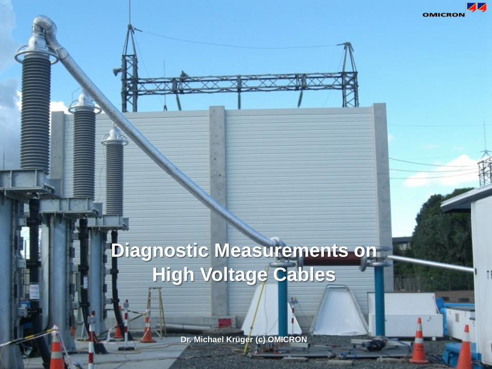
Commissioning of a 220kV Cable Cable
2
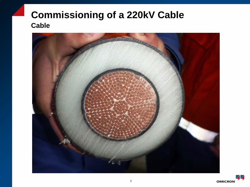
Commissioning of a 220kV Cable Overview
3
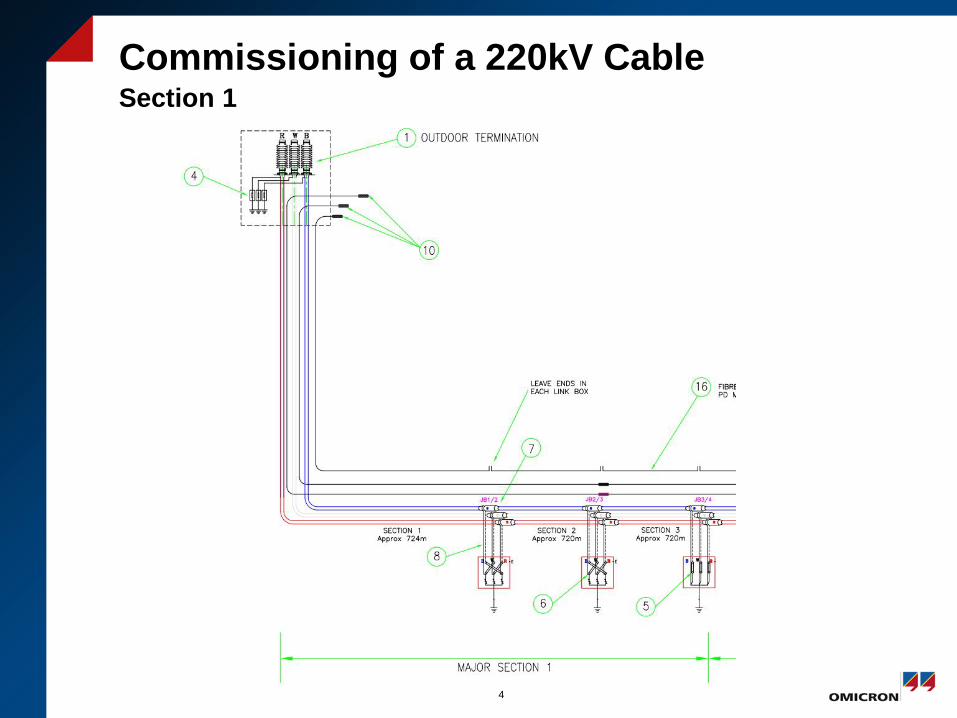
Commissioning of a 220kV Cable Section 1
4
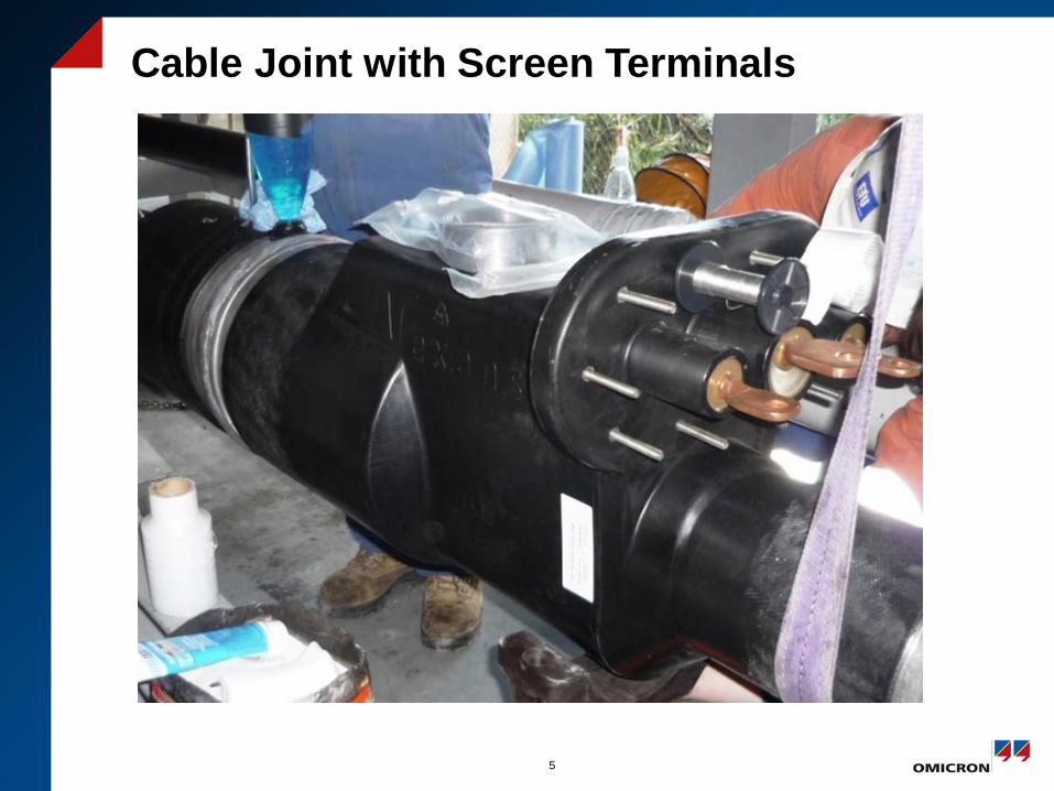
Cable Joint with Screen Terminals
5
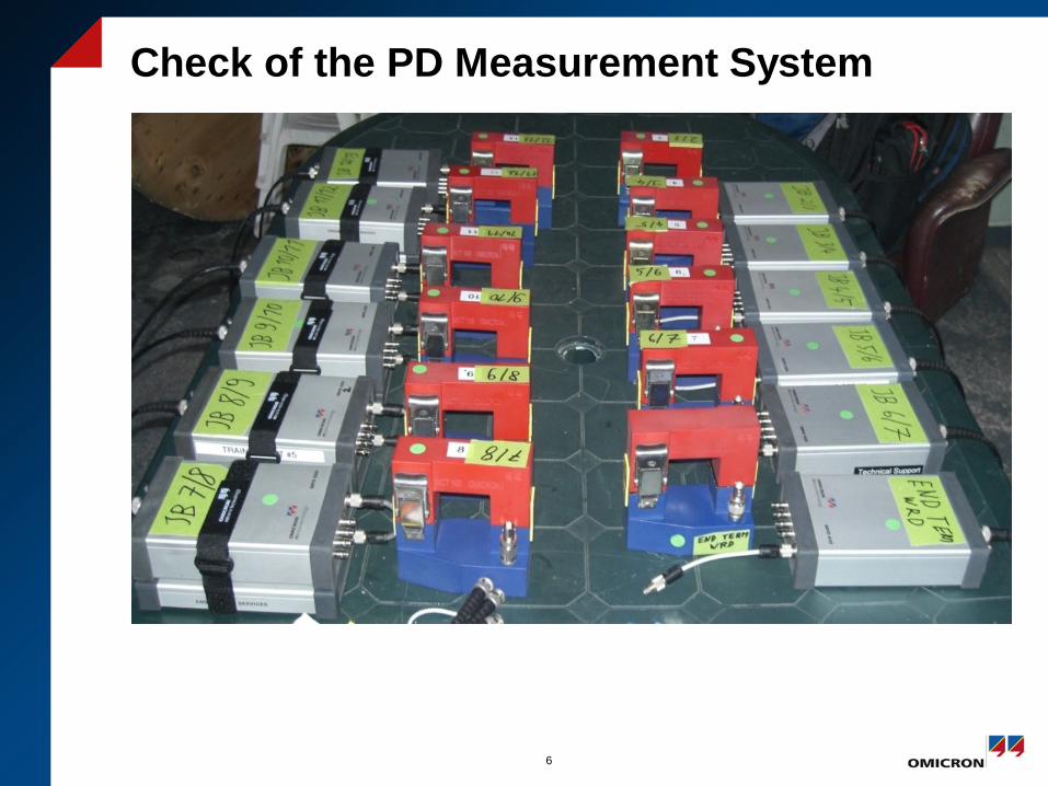
Check of the PD Measurement System
6
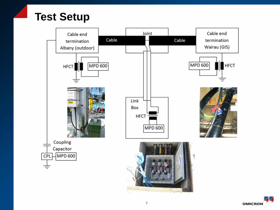
Test Setup
7
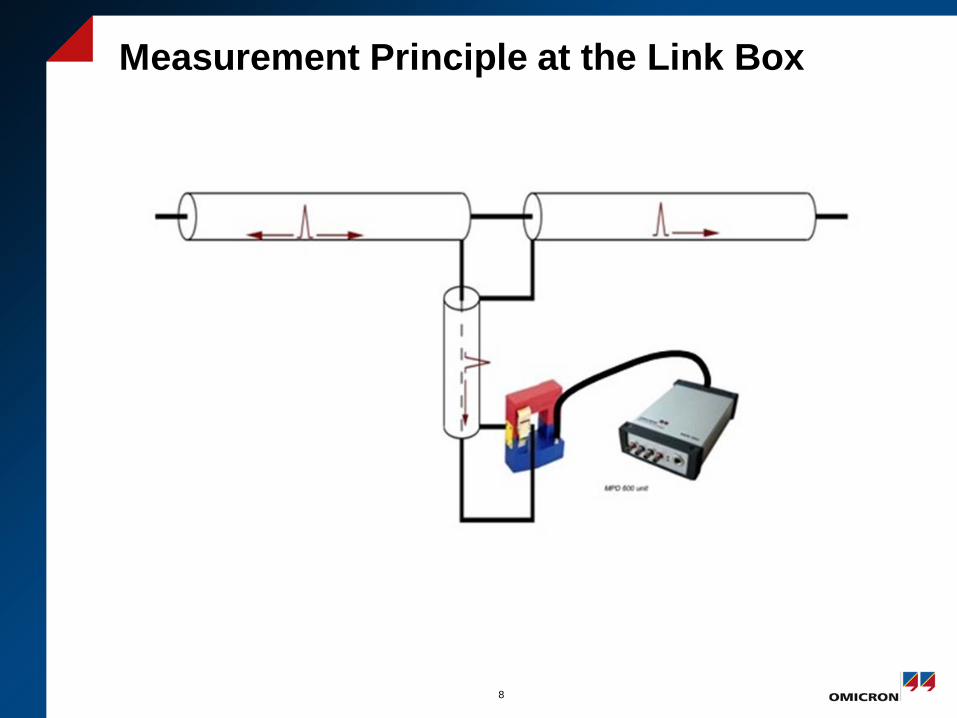
Measurement Principle at the Link Box
8
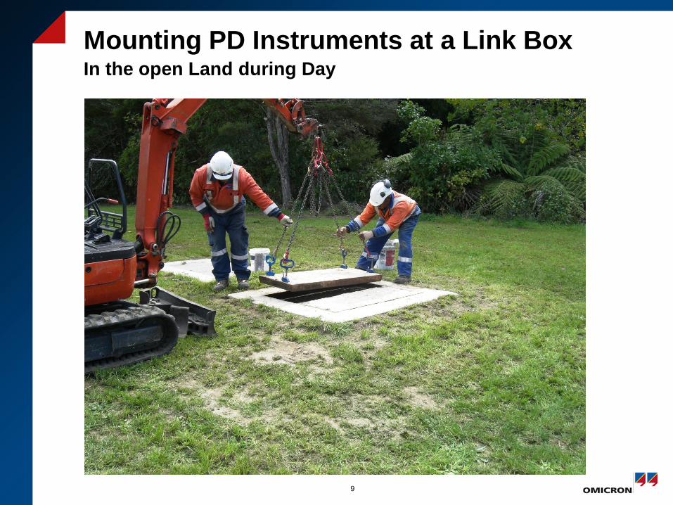
Mounting PD Instruments at a Link Box In the open Land during Day
9
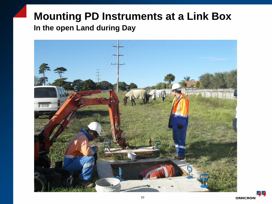
Mounting PD Instruments at a Link Box In the open Land during Day
10
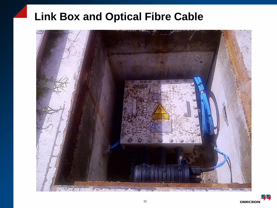
Link Box and Optical Fibre Cable
11
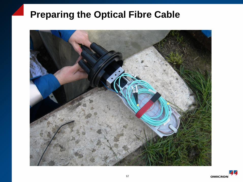
Preparing the Optical Fibre Cable
12
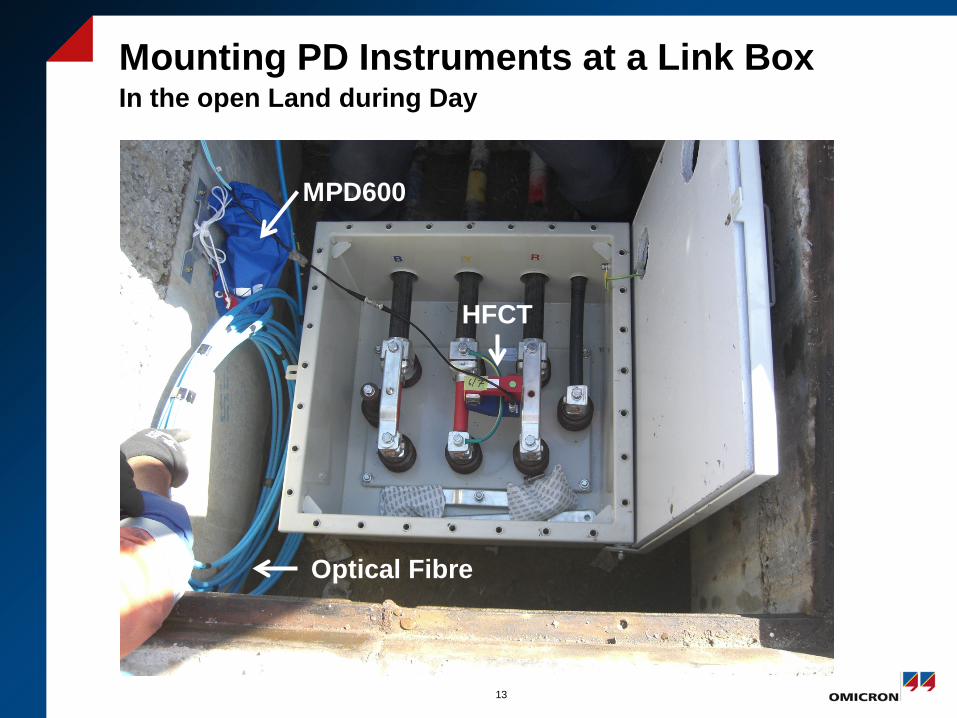
Mounting PD Instruments at a Link Box In the open Land during Day
13
MPD600
Optical Fibre
HFCT
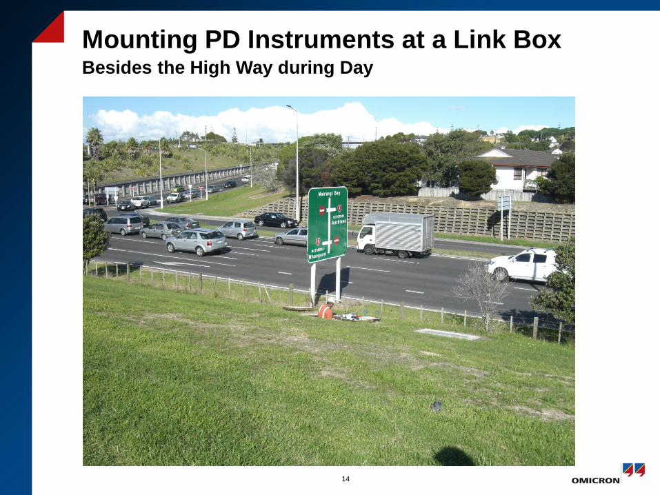
Mounting PD Instruments at a Link Box Besides the High Way during Day
14
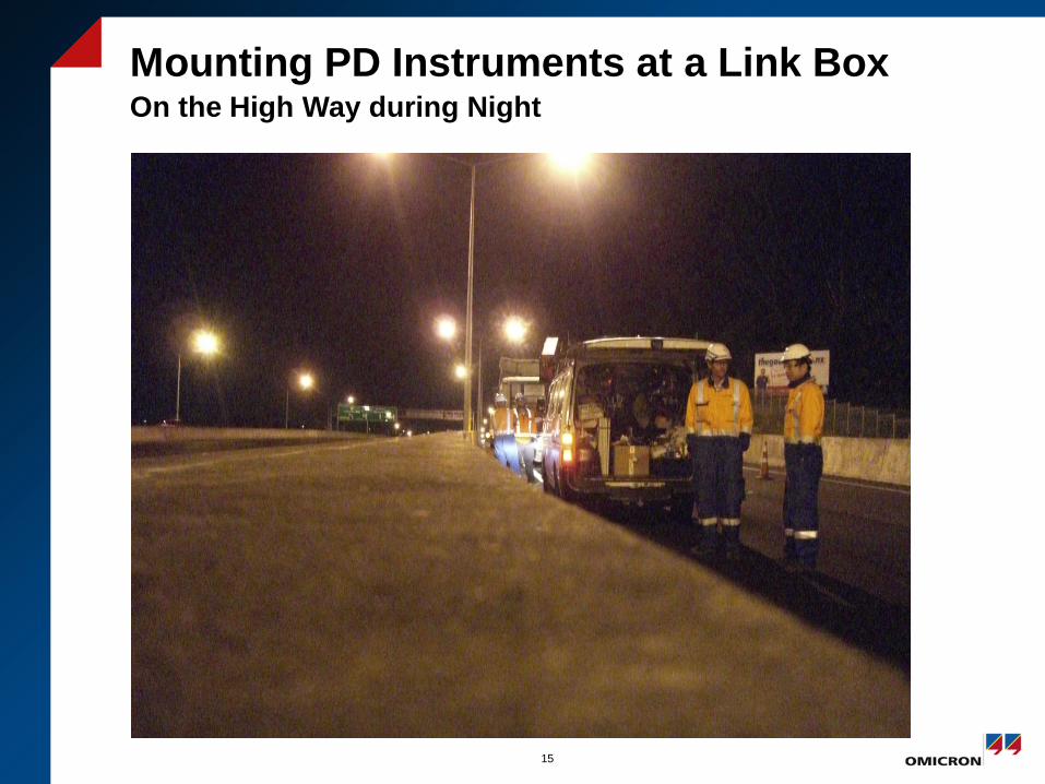
Mounting PD Instruments at a Link Box On the High Way during Night
15
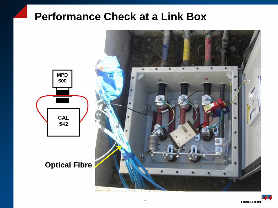
Performance Check at a Link Box
16
Optical Fibre
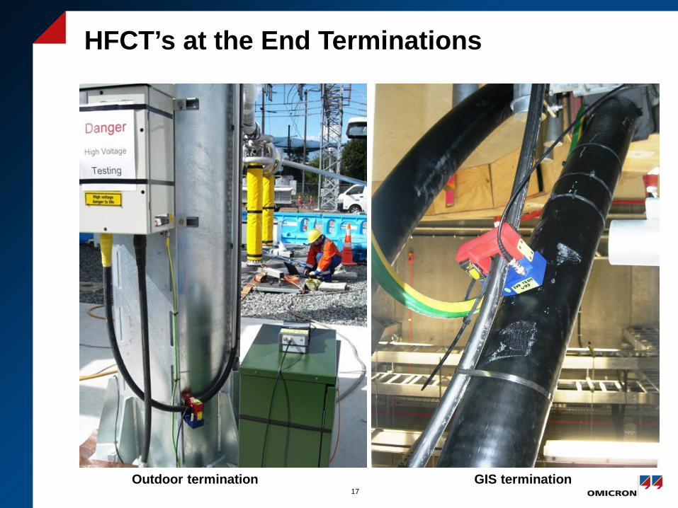
HFCT’s at the End Terminations
17 Outdoor termination GIS termination
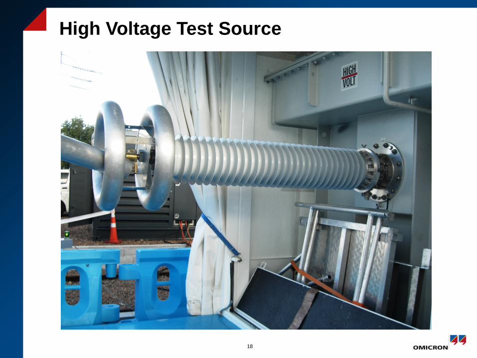
High Voltage Test Source
18
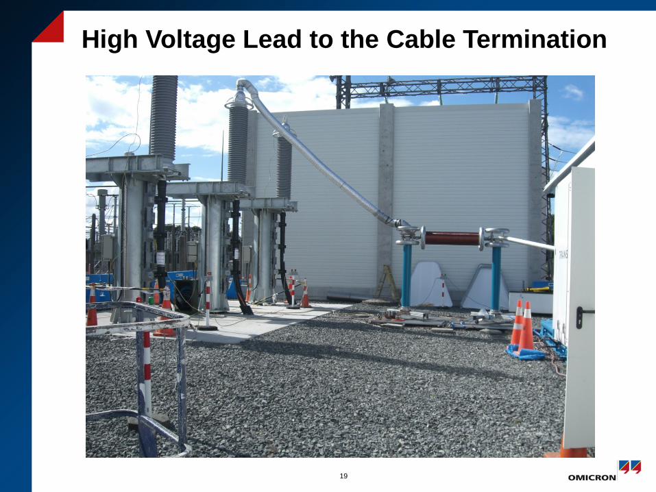
High Voltage Lead to the Cable Termination
19
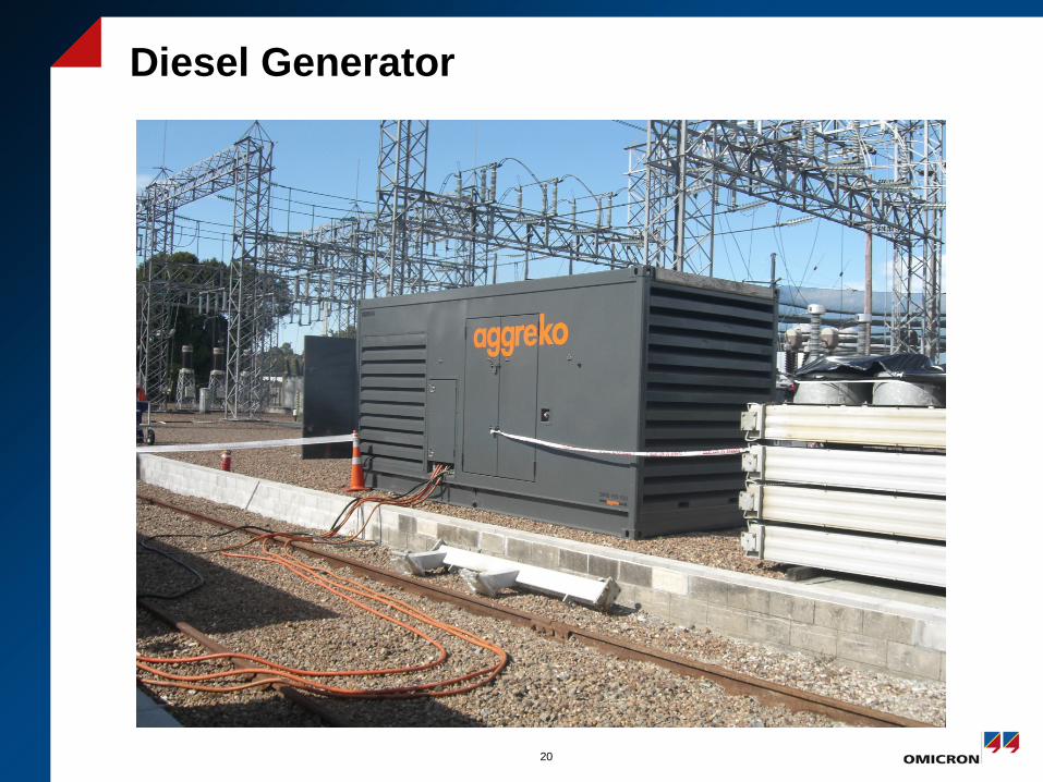
Diesel Generator
20
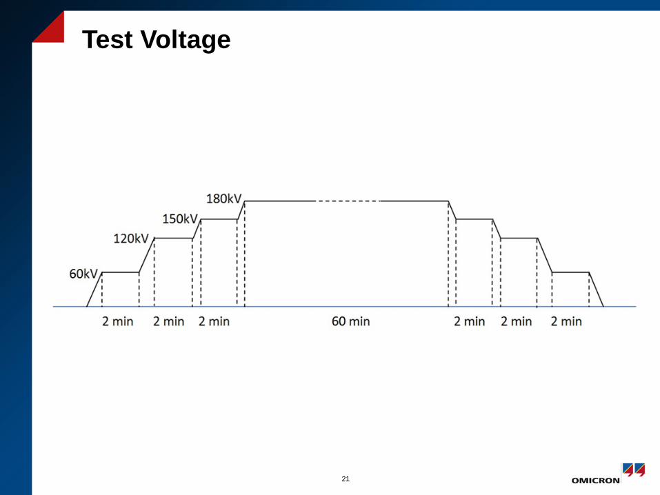
Test Voltage
21
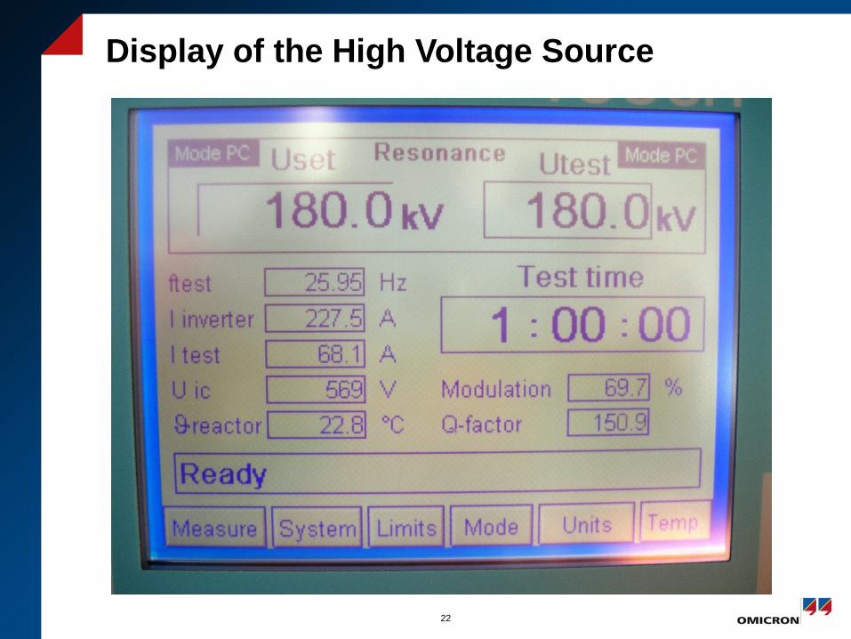
Display of the High Voltage Source
22
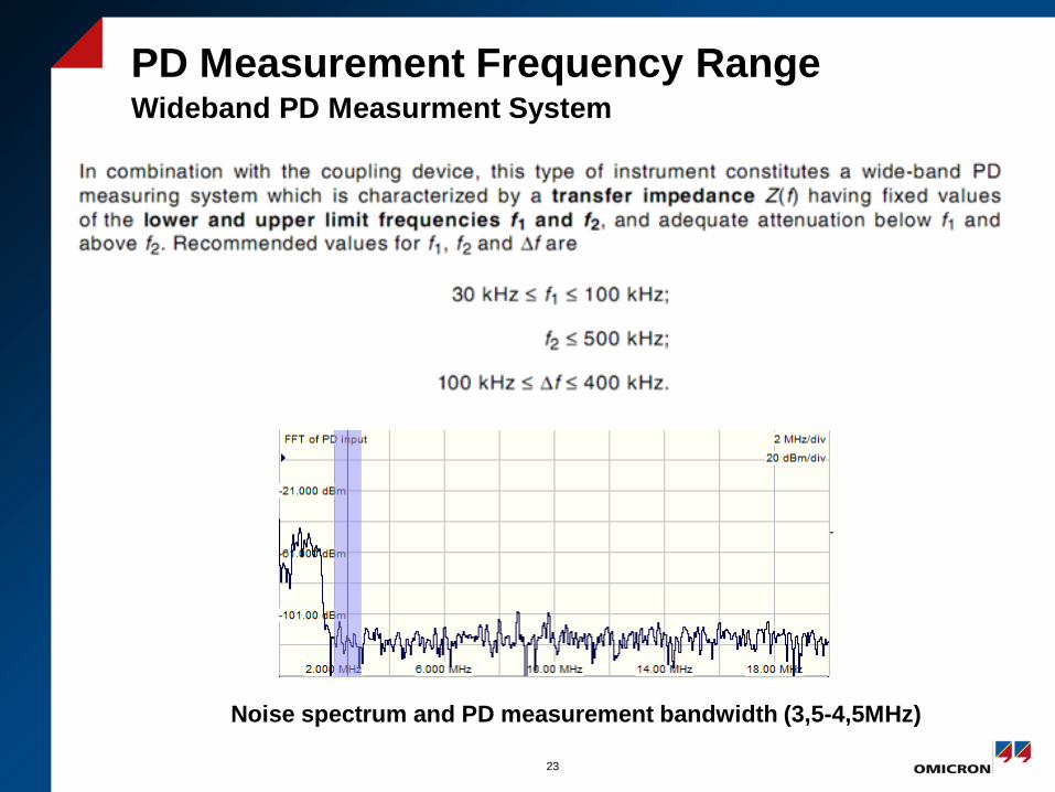
PD Measurement Frequency Range Wideband PD Measurment System
23
Noise spectrum and PD measurement bandwidth (3,5-4,5MHz)
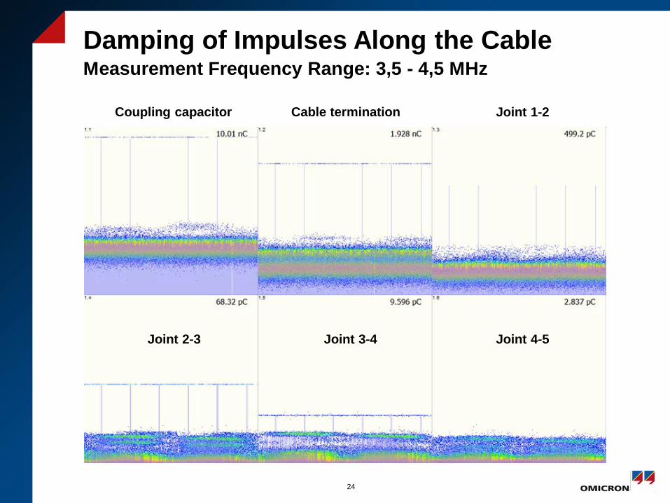
Damping of Impulses Along the Cable Measurement Frequency Range: 3,5 - 4,5 MHz
24
Coupling capacitor Cable termination Joint 1-2
Joint 2-3 Joint 3-4 Joint 4-5
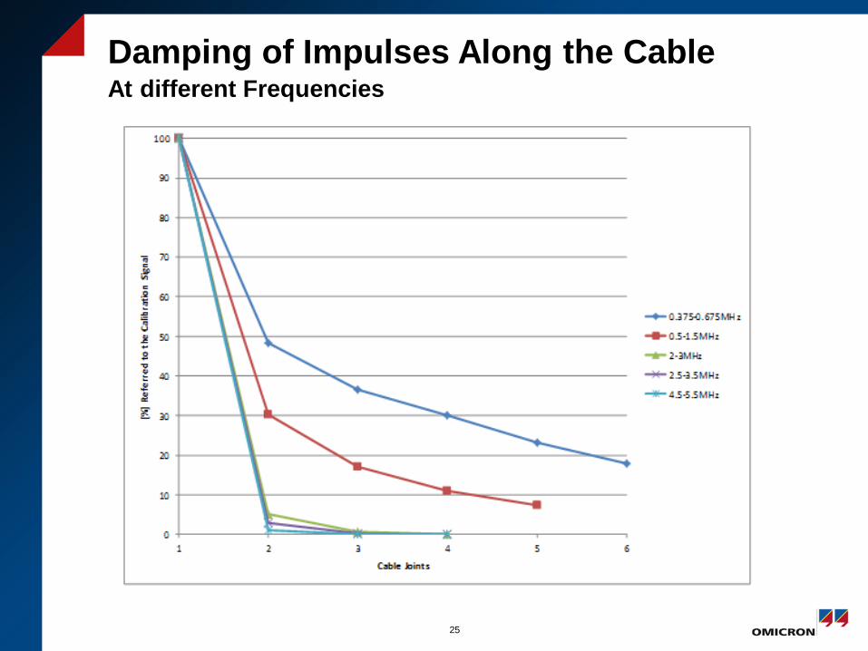
Damping of Impulses Along the Cable At different Frequencies
25
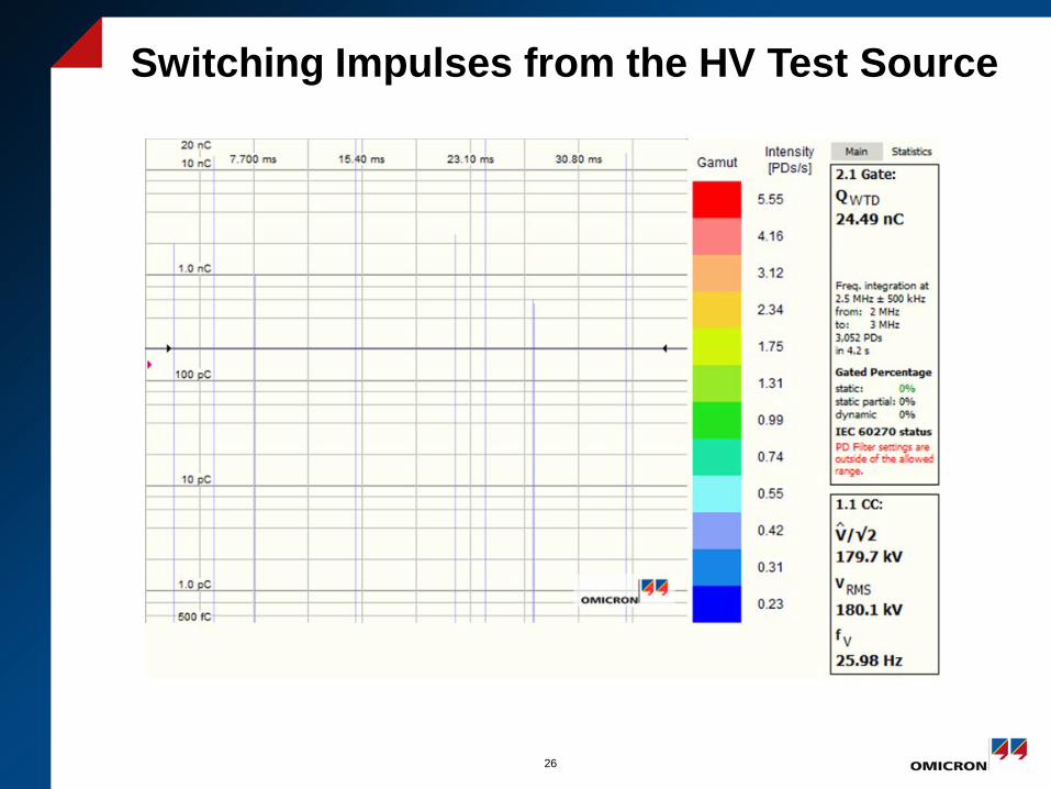
Switching Impulses from the HV Test Source
26
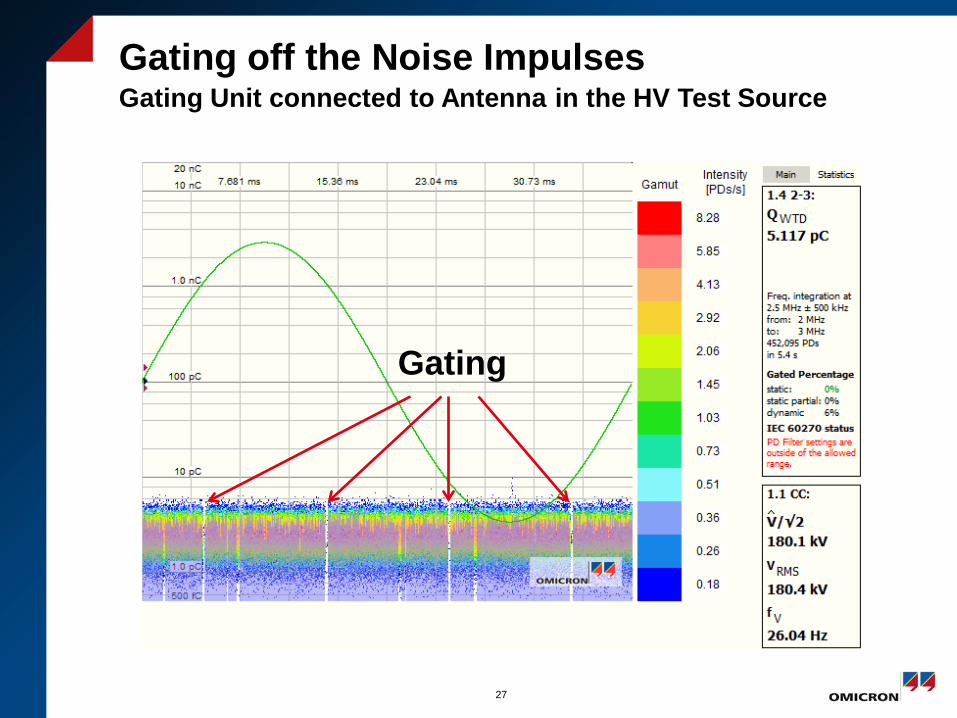
Gating off the Noise Impulses Gating Unit connected to Antenna in the HV Test Source
27
Gating
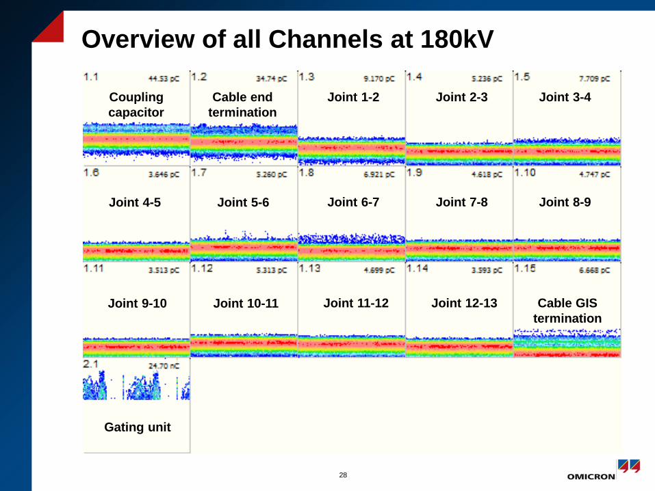
Overview of all Channels at 180kV
28
Coupling capacitor
Cable end termination
Joint 1-2 Joint 2-3 Joint 3-4
Joint 6-7 Joint 7-8 Joint 8-9 Joint 4-5 Joint 5-6
Joint 11-12 Joint 12-13 Cable GIS termination
Joint 9-10 Joint 10-11
Gating unit
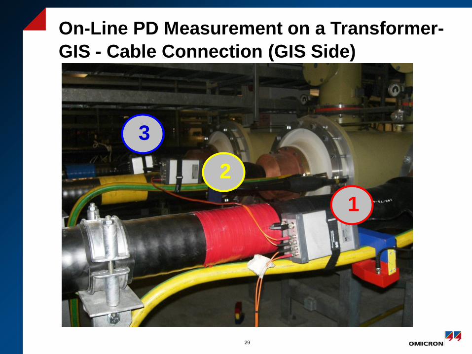
On-Line PD Measurement on a Transformer-GIS - Cable Connection (GIS Side)
29
2 1
3
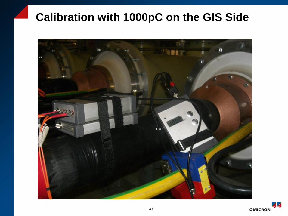
Calibration with 1000pC on the GIS Side
30
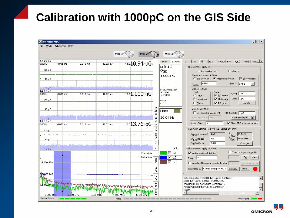
Calibration with 1000pC on the GIS Side
31
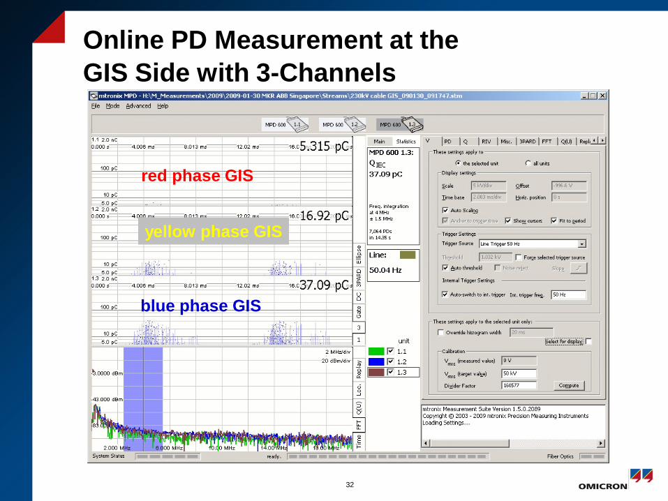
Online PD Measurement at the GIS Side with 3-Channels
32
yellow phase GIS
red phase GIS
blue phase GIS
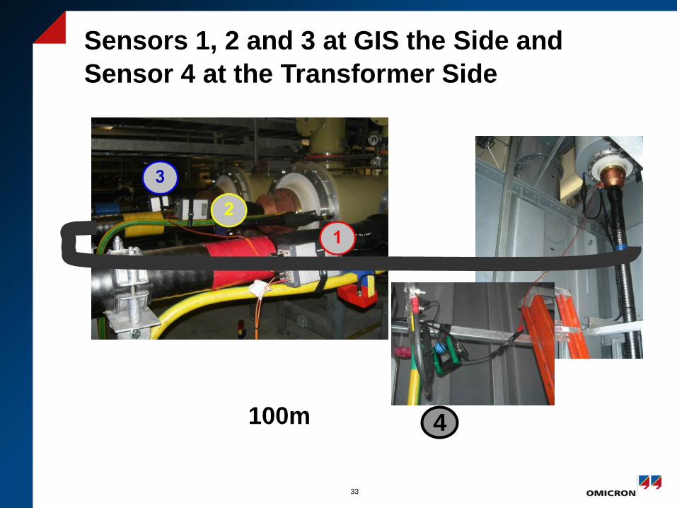
Sensors 1, 2 and 3 at GIS the Side and Sensor 4 at the Transformer Side
33
4 100m
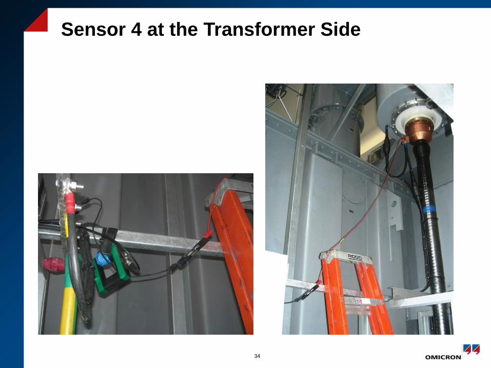
Sensor 4 at the Transformer Side
34
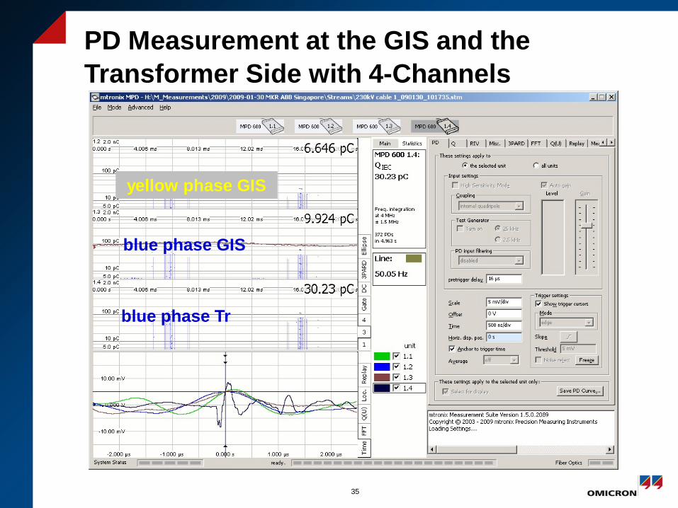
PD Measurement at the GIS and the Transformer Side with 4-Channels
35
blue phase GIS
blue phase Tr
yellow phase GIS
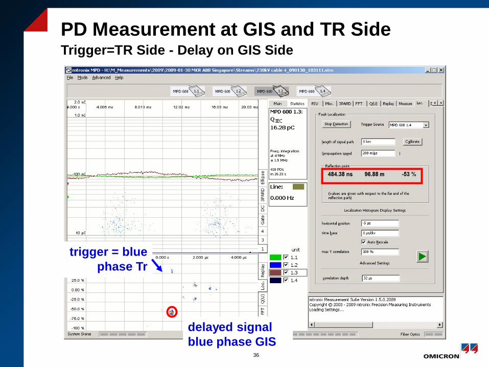
PD Measurement at GIS and TR Side Trigger=TR Side - Delay on GIS Side
36
delayed signal blue phase GIS
trigger = blue phase Tr
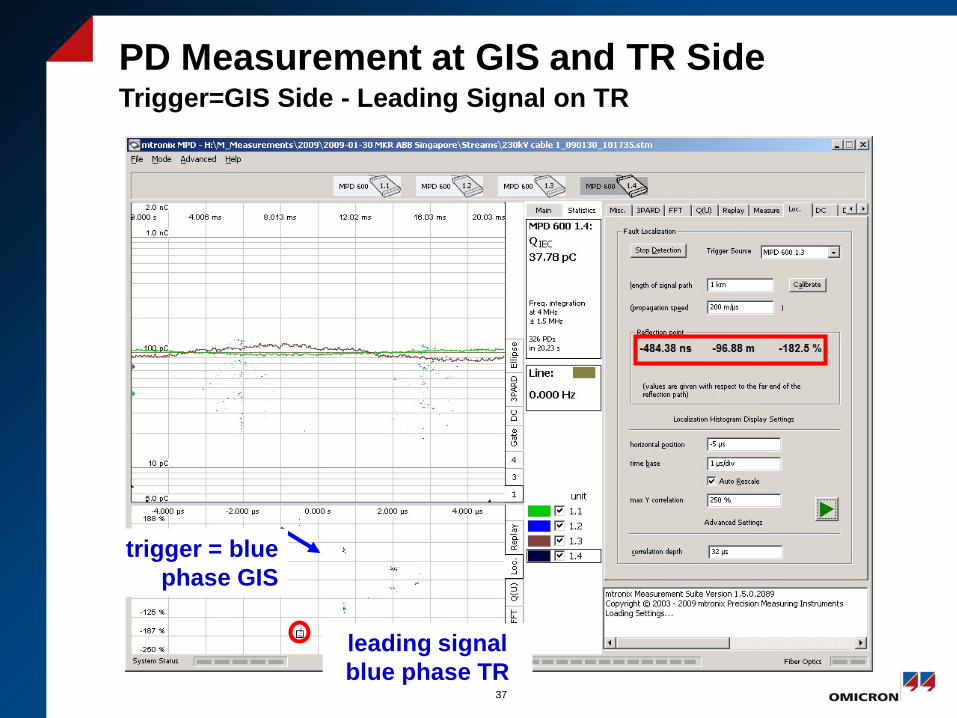
PD Measurement at GIS and TR Side Trigger=GIS Side - Leading Signal on TR
37
leading signal blue phase TR
trigger = blue phase GIS
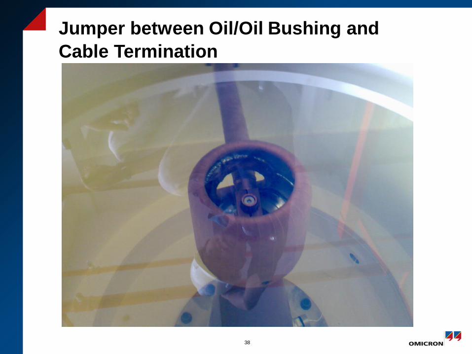
Jumper between Oil/Oil Bushing and Cable Termination
38

Jumper between Oil/Oil Bushing and Cable Termination
39