Embed Size (px)
Citation preview
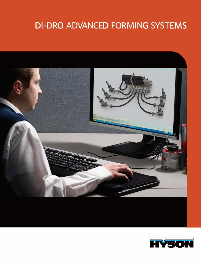
DDI-DRO O ADVANCED D FORMING G SYSTEMSEMS
WWE E PARTNER WITH RTNER WITH YOU
We partner with you to provide force-generating products andsolutions to lower your costs and increase your productivity inthe forming of manufactured parts.
TABLE OF CONTENTSIntroduction.................................................................2-3Features and Benefits....................................................4 How Di-Dro Works........................................................5 Case Studies................................................................6-7 Component Descriptions.............................................8 Dimensional Information: Control Center................9 Dimensional Information: Cylinders....................10-11 Hose & Fittings & Accessories...................................12 Custom Di-Dro Advanced Forming Systems.........13 How to Get Started.................................................14-15 Short Form Long Form with Equations
2
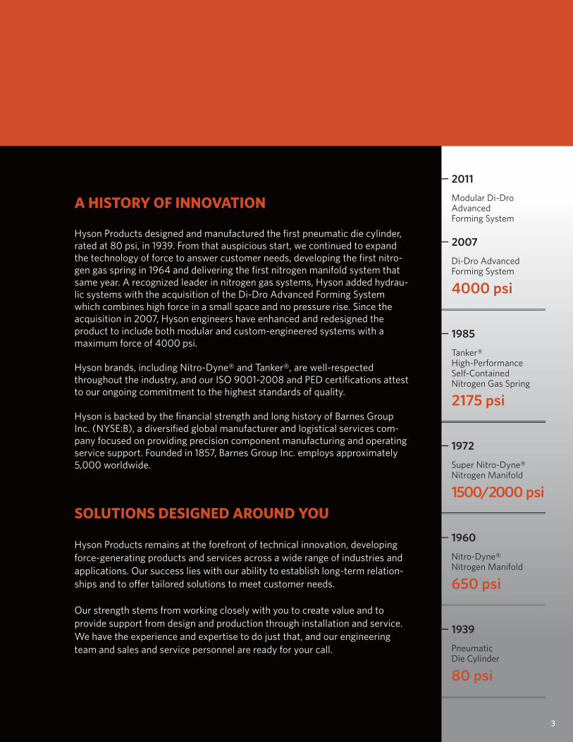
2007
4000 psi
Di-Dro AdvancedForming System
2011
Modular Di-DroAdvancedForming System
1985
2175 psi
Tanker®High-PerformanceSelf-ContainedNitrogen Gas Spring
1972
1500/2000 psi
Super Nitro-Dyne®Nitrogen Manifold
1960
650 psi
Nitro-Dyne®Nitrogen Manifold
1939
80 psi
PneumaticDie Cylinder
SOLUTIONS DESIGNED AROUND YOU
Hyson Products remains at the forefront of technical innovation, developing force-generating products and services across a wide range of industries and applications. Our success lies with our ability to establish long-term relation-ships and to offer tailored solutions to meet customer needs.
Our strength stems from working closely with you to create value and to provide support from design and production through installation and service. We have the experience and expertise to do just that, and our engineering team and sales and service personnel are ready for your call.
A HISTORY OF INNOVATION
Hyson Products designed and manufactured the first pneumatic die cylinder, rated at 80 psi, in 1939. From that auspicious start, we continued to expand the technology of force to answer customer needs, developing the first nitro-gen gas spring in 1964 and delivering the first nitrogen manifold system that same year. A recognized leader in nitrogen gas systems, Hyson added hydrau-lic systems with the acquisition of the Di-Dro Advanced Forming System which combines high force in a small space and no pressure rise. Since the acquisition in 2007, Hyson engineers have enhanced and redesigned the product to include both modular and custom-engineered systems with a maximum force of 4000 psi.
Hyson brands, including Nitro-Dyne® and Tanker®, are well-respected throughout the industry, and our ISO 9001-2008 and PED certifications attest to our ongoing commitment to the highest standards of quality.
Hyson is backed by the financial strength and long history of Barnes Group Inc. (NYSE:B), a diversified global manufacturer and logistical services com-pany focused on providing precision component manufacturing and operating service support. Founded in 1857, Barnes Group Inc. employs approximately 5,000 worldwide.
3
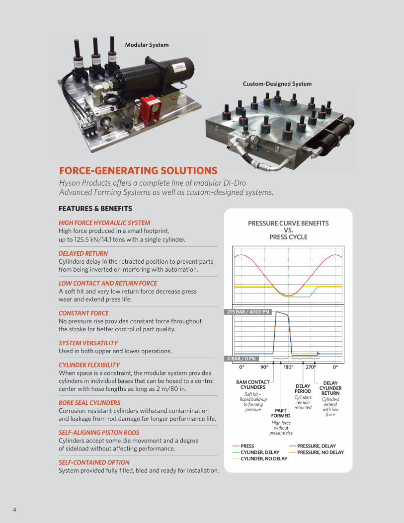
FORCE-GENERATING SOLUTIONSHyson Products offers a complete line of modular Di-DroAdvanced Forming Systems as well as custom-designed systems.
4
Modular SystemModular System
Custom-Designed System
ONS
g y
PRESSCYLINDER, DELAY
PRESSURE, DELAYPRESSURE, NO DELAY
CYLINDER, NO DELAY
PRESSURE CURVE BENEFITSVS.
PRESS CYCLE
90° 180°0° 0°270°
RAM CONTACTCYLINDERS
Soft hit – Rapid build-up
to formingpressure
DELAYCYLINDERRETURNCylinders
extendwith low
forcePART
FORMEDHigh force
withoutpressure rise
DELAYPERIODCylindersremain
retracted
0 BAR / 0 PSI
275 BAR / 4000 PSI
FEATURES & BENEFITS
HIGH FORCE HYDRAULIC SYSTEMHigh force produced in a small footprint, up to 125.5 kN/14.1 tons with a single cylinder.
DELAYED RETURNCylinders delay in the retracted position to prevent partsfrom being inverted or interfering with automation.
LOW CONTACT AND RETURN FORCEA soft hit and very low return force decrease presswear and extend press life.
CONSTANT FORCENo pressure rise provides constant force throughoutthe stroke for better control of part quality.
SYSTEM VERSATILITYUsed in both upper and lower operations.
CYLINDER FLEXIBILITYWhen space is a constraint, the modular system providescylinders in individual bases that can be hosed to a controlcenter with hose lengths as long as 2 m/80 in.
BORE SEAL CYLINDERSCorrosion-resistant cylinders withstand contaminationand leakage from rod damage for longer performance life.
SELF-ALIGNING PISTON RODSCylinders accept some die movement and a degreeof sideload without affecting performance.
SELF-CONTAINED OPTIONSystem provided fully filled, bled and ready for installation.
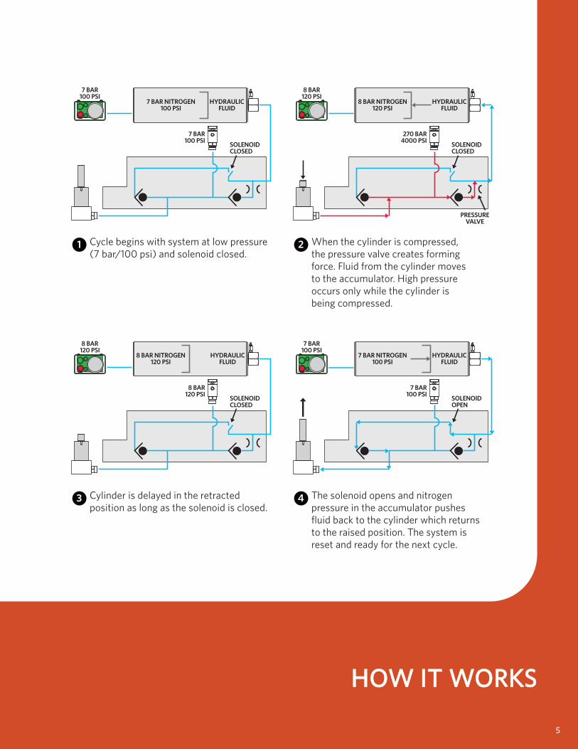
HOW IT WORKSHOW IT WORKS
7 BAR100 PSI
7 BAR100 PSI
7 BAR NITROGEN100 PSI
HYDRAULICFLUID
Cycle begins with system at low pressure(7 bar/100 psi) and solenoid closed.
1
8 BAR120 PSI
270 BAR4000 PSI
8 BAR NITROGEN120 PSI
HYDRAULICFLUID
When the cylinder is compressed,the pressure valve creates formingforce. Fluid from the cylinder movesto the accumulator. High pressureoccurs only while the cylinder isbeing compressed.
2
8 BAR120 PSI
8 BAR120 PSI
Cylinder is delayed in the retractedposition as long as the solenoid is closed.
3
7 BAR100 PSI
7 BAR100 PSI
The solenoid opens and nitrogenpressure in the accumulator pushesfluid back to the cylinder which returnsto the raised position. The system isreset and ready for the next cycle.
4
8 BAR NITROGEN120 PSI
HYDRAULICFLUID
7 BAR NITROGEN100 PSI
SOLENOIDCLOSED
SOLENOIDCLOSED
SOLENOIDCLOSED
HYDRAULICFLUID
SOLENOIDOPEN
5
PRESSUREVALVE
CCASE STE STUDIESIES
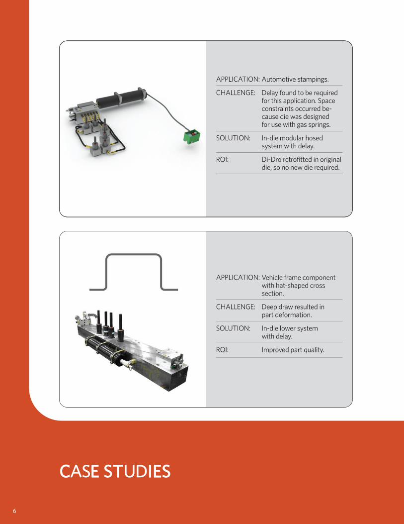
APPLICATION: Vehicle frame component with hat-shaped cross section.
CHALLENGE: Deep draw resulted in part deformation.
SOLUTION: In-die lower system with delay.
ROI: Improved part quality.
APPLICATION: Automotive stampings.
CHALLENGE: Delay found to be required for this application. Space constraints occurred be- cause die was designed for use with gas springs.
SOLUTION: In-die modular hosed system with delay.
ROI: Di-Dro retrofitted in original die, so no new die required.
6
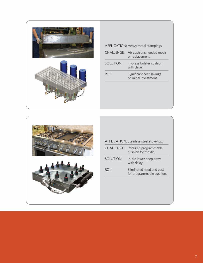
APPLICATION: Stainless steel stove top.
CHALLENGE: Required programmable cushion for the die.
SOLUTION: In-die lower deep draw with delay.
ROI: Eliminated need and cost for programmable cushion.
APPLICATION: Heavy metal stampings.
CHALLENGE: Air cushions needed repair or replacement.
SOLUTION: In-press bolster cushion with delay.
ROI: Significant cost savings on initial investment.
7
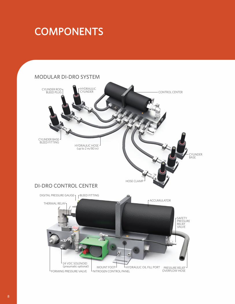
MODULAR DI-DRO SYSTEM
CONTROL CENTER
CYLINDERBASE
HOSE CLAMP
HYDRAULIC HOSE(up to 2 m/80 in)
CYLINDER BASEBLEED FITTING
CYLINDER RODBLEED PLUG
HYDRAULICCYLINDER
COMPONENTSCOMPONENTS
8
THERMAL RELAY
DIGITAL PRESSURE GAUGE
SAFETYPRESSURERELIEFVALVE
ACCUMULATOR
BLEED FITTING
FORMING PRESSURE VALVE NITROGEN CONTROL PANELMOUNT FOOT PRESSURE RELIEF
OVERFLOW HOSE
24 VDC SOLENOID(pneumatic optional) HYDRAULIC OIL FILL PORT
DI-DRO CONTROL CENTER
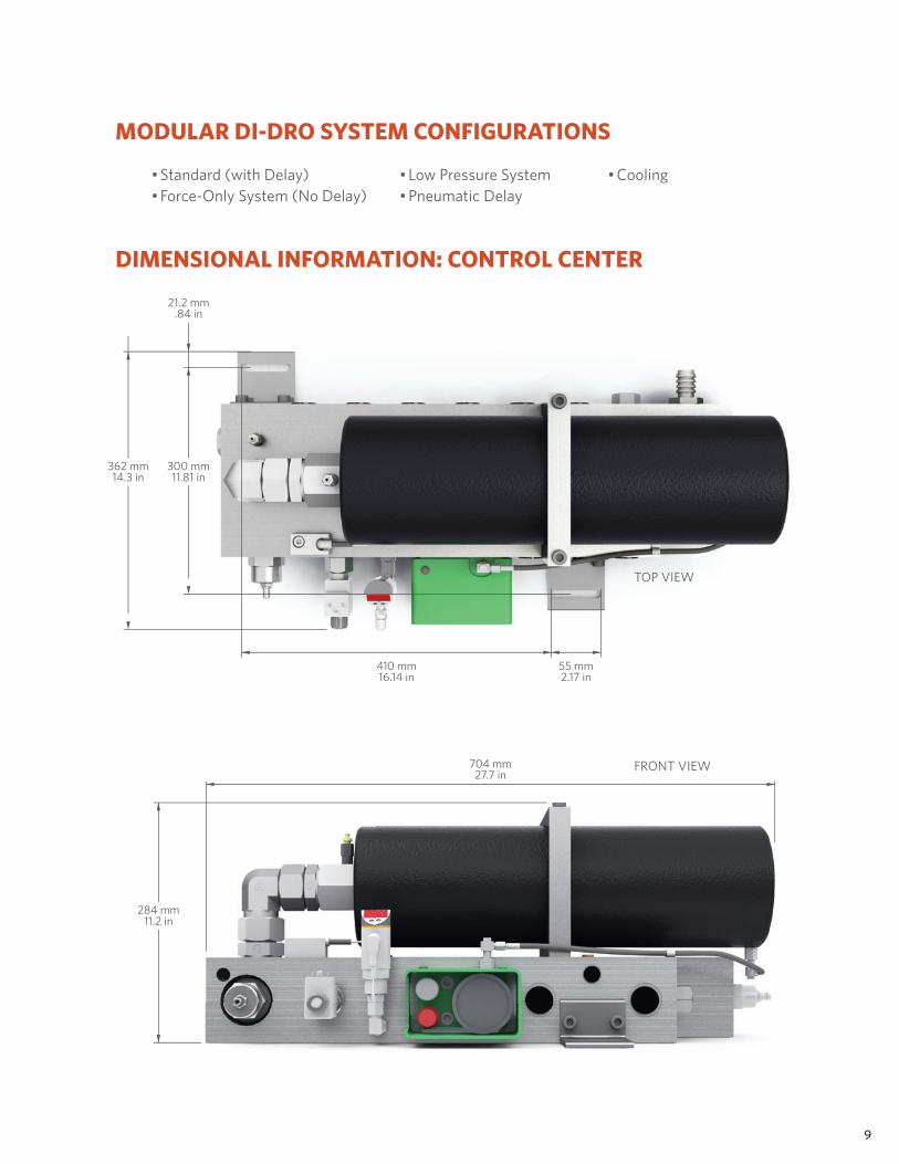
MODULAR DI-DRO SYSTEM CONFIGURATIONS
DIMENSIONAL INFORMATION: CONTROL CENTER
• Standard (with Delay)• Force-Only System (No Delay)
• Low Pressure System• Pneumatic Delay
• Cooling
410 mm16.14 in
362 mm14.3 in
300 mm11.81 in
21.2 mm.84 in
55 mm2.17 in
TOP VIEW
704 mm27.7 in
284 mm11.2 in
FRONT VIEW
9
PRESSURE MEDIUM Hydraulic OilMAXIMUM PRESSURE 275 bar/4000 psiMINIMUM PRESSURE 25 bar/360 psiMAX. OPERATING TEMP. 93°C/200°FMAX. PISTON ROD VELOCITY 96 m/min/315 ft/min
MAX. UTILIZED STROKE 100% MAX. STROKES PER MINUTE Dependant on HeatBASE BLEED FITTING 4014007CYLINDER ROD BLEED PLUG NF-771-3-V-ZLG
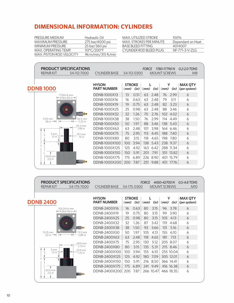
DIMENSIONAL INFORMATION: CYLINDERS
10
DDNB 1000
PRODUCT SPECIFICATIONSREPAIR KIT 54-112-7000 CYLINDER BASE 54-112-0300 MOUNT SCREWS M8
FORCE 1780-17790 N 0.2-2.0 TONS
77.8±1.6 mm3.06±.06 in
9.25 mm.36 in
3 mm.12 in
50.8 mm2.0 in
Y
L
S
56.5 mm2.22 in
50.3 mm1.98 in
19.1 mm.75 in
HYSON STROKE L Y MAX QTYPART NUMBER (mm) (in) (mm) (in) (mm) (in) (per system)
DDNB-2400X16 16 0.63 80 3.15 96 3.78 6DDNB-2400X19 19 0.75 80 3.15 99 3.90 6DDNB-2400X25 25 0.98 80 3.15 105 4.13 6DDNB-2400X32 32 1.26 87 3.42 119 4.68 6DDNB-2400X38 38 1.50 93 3.66 131 5.16 6DDNB-2400X50 50 1.97 105 4.13 155 6.10 6DDNB-2400X63 63 2.48 118 4.65 181 7.13 6DDNB-2400X75 75 2.95 130 5.12 205 8.07 6DDNB-2400X80 80 3.15 135 5.31 215 8.46 6DDNB-2400X100 100 3.94 155 6.10 255 10.04 6DDNB-2400X125 125 4.92 180 7.09 305 12.01 6DDNB-2400X150 150 5.91 216 8.50 366 14.41 6DDNB-2400X175 175 6.89 241 9.49 416 16.38 6DDNB-2400X200 200 7.87 266 10.47 466 18.35 6
103.2±1.6 mm4.06±.06 in
13.25 mm.52 in
3 mm.12 in
63.5 mm2.5 in
Y
L
S
73.5 mm2.89 in
69.9 mm2.75 in
31.8 mm1.25 in
PRODUCT SPECIFICATIONSREPAIR KIT 54-175-7000 CYLINDER BASE 54-175-0300 MOUNT SCREWS M10
FORCE 4450-42700 N 0.5-4.8 TONS
DDNB 2400
HYSON STROKE L Y MAX QTYPART NUMBER (mm) (in) (mm) (in) (mm) (in) (per system)
DDNB-1000X13 13 0.51 63 2.48 76 2.99 6 DDNB-1000X16 16 0.63 63 2.48 79 3.11 6 DDNB-1000X19 19 0.75 63 2.48 82 3.23 6 DDNB-1000X25 25 0.98 63 2.48 88 3.46 6 DDNB-1000X32 32 1.26 70 2.76 102 4.02 6 DDNB-1000X38 38 1.50 76 2.99 114 4.49 6 DDNB-1000X50 50 1.97 88 3.46 138 5.43 6 DDNB-1000X63 63 2.48 101 3.98 164 6.46 6 DDNB-1000X75 75 2.95 113 4.45 188 7.40 6 DDNB-1000X80 80 3.15 118 4.65 198 7.80 6 DDNB-1000X100 100 3.94 138 5.43 238 9.37 6 DDNB-1000X125 125 4.92 163 6.42 288 11.34 6 DDNB-1000X150 150 5.91 201 7.91 351 13.82 6 DDNB-1000X175 175 6.89 226 8.90 401 15.79 6DDNB-1000X200 200 7.87 251 9.88 451 17.76 6
HYSON STROKE L Y MAX QTYPART NUMBER (mm) (in) (mm) (in) (mm) (in) (per system)
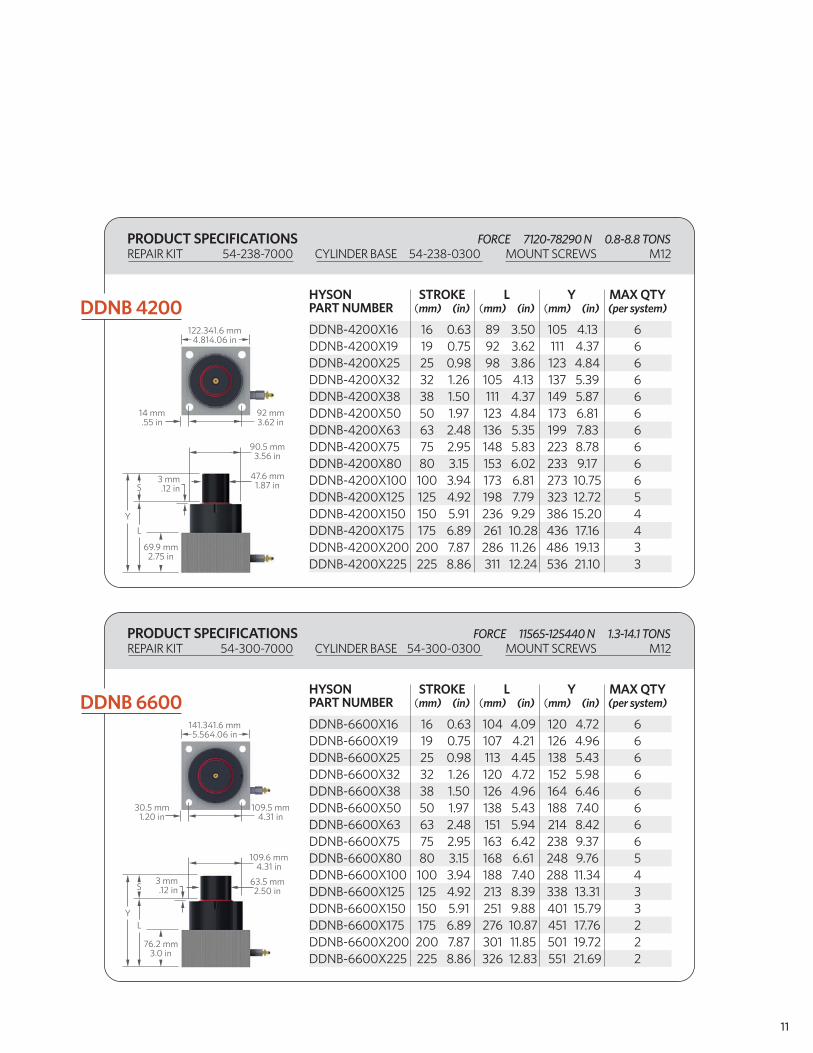
DDNB-4200X16 16 0.63 89 3.50 105 4.13 6DDNB-4200X19 19 0.75 92 3.62 111 4.37 6DDNB-4200X25 25 0.98 98 3.86 123 4.84 6DDNB-4200X32 32 1.26 105 4.13 137 5.39 6DDNB-4200X38 38 1.50 111 4.37 149 5.87 6DDNB-4200X50 50 1.97 123 4.84 173 6.81 6DDNB-4200X63 63 2.48 136 5.35 199 7.83 6DDNB-4200X75 75 2.95 148 5.83 223 8.78 6DDNB-4200X80 80 3.15 153 6.02 233 9.17 6DDNB-4200X100 100 3.94 173 6.81 273 10.75 6DDNB-4200X125 125 4.92 198 7.79 323 12.72 5DDNB-4200X150 150 5.91 236 9.29 386 15.20 4DDNB-4200X175 175 6.89 261 10.28 436 17.16 4DDNB-4200X200 200 7.87 286 11.26 486 19.13 3DDNB-4200X225 225 8.86 311 12.24 536 21.10 3
122.3±1.6 mm4.81±.06 in
14 mm.55 in
3 mm.12 in
69.9 mm2.75 in
Y
L
S
92 mm3.62 in
90.5 mm3.56 in
47.6 mm1.87 in
HYSON STROKE L Y MAX QTYPART NUMBER (mm) (in) (mm) (in) (mm) (in) (per system)
DDNB-6600X16 16 0.63 104 4.09 120 4.72 6 DDNB-6600X19 19 0.75 107 4.21 126 4.96 6 DDNB-6600X25 25 0.98 113 4.45 138 5.43 6 DDNB-6600X32 32 1.26 120 4.72 152 5.98 6 DDNB-6600X38 38 1.50 126 4.96 164 6.46 6 DDNB-6600X50 50 1.97 138 5.43 188 7.40 6 DDNB-6600X63 63 2.48 151 5.94 214 8.42 6 DDNB-6600X75 75 2.95 163 6.42 238 9.37 6 DDNB-6600X80 80 3.15 168 6.61 248 9.76 5 DDNB-6600X100 100 3.94 188 7.40 288 11.34 4 DDNB-6600X125 125 4.92 213 8.39 338 13.31 3 DDNB-6600X150 150 5.91 251 9.88 401 15.79 3 DDNB-6600X175 175 6.89 276 10.87 451 17.76 2 DDNB-6600X200 200 7.87 301 11.85 501 19.72 2DDNB-6600X225 225 8.86 326 12.83 551 21.69 2
141.3±1.6 mm5.56±.06 in
30.5 mm1.20 in
3 mm.12 in
76.2 mm3.0 in
YL
S
109.5 mm4.31 in
109.6 mm4.31 in
63.5 mm2.50 in
PRODUCT SPECIFICATIONSREPAIR KIT 54-238-7000 CYLINDER BASE 54-238-0300 MOUNT SCREWS M12
FORCE 7120-78290 N 0.8-8.8 TONS
PRODUCT SPECIFICATIONSREPAIR KIT 54-300-7000 CYLINDER BASE 54-300-0300 MOUNT SCREWS M12
FORCE 11565-125440 N 1.3-14.1 TONS
DDNB 4200
DDNB 6600
11
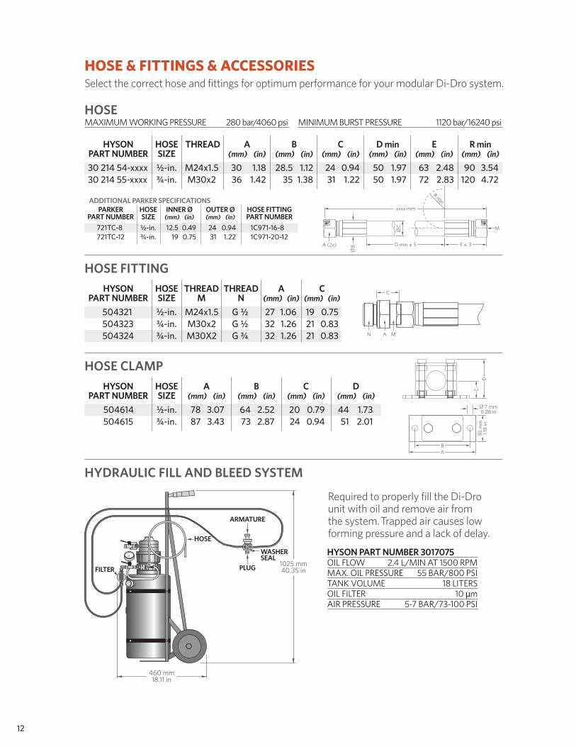
ADDITIONAL PARKER SPECIFICATIONS
HOSE & FITTINGS & ACCESSORIESSelect the correct hose and fittings for optimum performance for your modular Di-Dro system.
HOSE
12
Required to properly fill the Di-Drounit with oil and remove air fromthe system. Trapped air causes lowforming pressure and a lack of delay.
HYSON PART NUMBER 3017075 OIL FLOW 2.4 L/MIN AT 1500 RPMMAX. OIL PRESSURE 55 BAR/800 PSITANK VOLUME 18 LITERSOIL FILTER 10 µmAIR PRESSURE 5-7 BAR/73-100 PSI
E ± 3D min ± 5
Ø B
Ø C
xxxx mm
R min
M
A (2x)
C
N A M
Ø 7 mm0.28 in
30 m
m1.1
8 in
BA
DC
1025 mm40.35 inPLUG
ARMATURE
WASHERSEAL
HOSE
FILTER
460 mm18.11 in
HOSE CLAMP
MAXIMUM WORKING PRESSURE 280 bar/4060 psi MINIMUM BURST PRESSURE 1120 bar/16240 psi
HYSON HOSE THREAD A B C D min E R min PART NUMBER SIZE (mm) (in) (mm) (in) (mm) (in) (mm) (in) (mm) (in) (mm) (in)
30 214 54-xxxx ½-in. M24x1.5 30 1.18 28.5 1.12 24 0.94 50 1.97 63 2.48 90 3.54 30 214 55-xxxx ¾-in. M30x2 36 1.42 35 1.38 31 1.22 50 1.97 72 2.83 120 4.72
HOSE FITTING HYSON HOSE THREAD THREAD A C PART NUMBER SIZE M N (mm) (in) (mm) (in)
504321 ½-in. M24x1.5 G ½ 27 1.06 19 0.75 504323 ¾-in. M30x2 G ½ 32 1.26 21 0.83 504324 ¾-in. M30X2 G ¾ 32 1.26 21 0.83
HYDRAULIC FILL AND BLEED SYSTEM
HYSON HOSE A B C D PART NUMBER SIZE (mm) (in) (mm) (in) (mm) (in) (mm) (in)
504614 ½-in. 78 3.07 64 2.52 20 0.79 44 1.73 504615 ¾-in. 87 3.43 73 2.87 24 0.94 51 2.01
PARKER HOSE INNER Ø OUTER Ø HOSE FITTING PART NUMBER SIZE (mm) (in) (mm) (in) PART NUMBER 721TC-8 ½-in. 12.5 0.49 24 0.94 1C971-16-8 721TC-12 ¾-in. 19 0.75 31 1.22 1C971-20-12
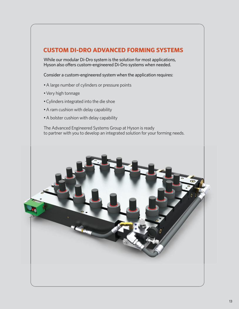
While our modular Di-Dro system is the solution for most applications,Hyson also offers custom-engineered Di-Dro systems when needed.
Consider a custom-engineered system when the application requires:
• A large number of cylinders or pressure points
• Very high tonnage
• Cylinders integrated into the die shoe
• A ram cushion with delay capability
• A bolster cushion with delay capability The Advanced Engineered Systems Group at Hyson is readyto partner with you to develop an integrated solution for your forming needs.
13
CUSTOM DI-DRO ADVANCED FORMING SYSTEMS

HOW TO GET STARTEDTo provide the system to fit your needs, complete the required short form. You may choose to completethe long form which includes equations that will allow you to select your system components.Email to [email protected] or fax to 440-526-6807. For more information or to request these formsin English measures, call toll-free 800-876-4976 or 440-526-5900.
14
LONG FORM (optional)
EQUATIONS
SHORT FORM (required)
1. PRESSURE POINT FORCE (CYLINDER SIZE SELECTION) total force required (N) number of pressure points
Notes: Choose a cylinder size (see right) where the calculated tonnage is within the cylinder’s range, near mid-range is preferred. Smaller cylinder sizes preferred.
■
■
■
■
2. PRESSURE total force required (N) x 10 cyl. qty. x piston area (mm2)
Notes: Pressure MUST be less than 275 bar. IF NOT: 1. Increase quantity of cylinders. 2. Increase size of cylinders.
1. Number of pressure points
2. Total force required (N)
3. Cylinder work stroke (mm)
4. Parts per minute (ppm)
5a. Maximum ram speed during work stroke (m/s)OR
5b. Mechanical press stroke length (mm)
6. Maximum anticipated press speed in strokes per minute (spm)
= (N)
= bar
5. HEAT GENERATION total force (N) x work stroke (mm) x parts per minute (ppm) = kW 60,000,000 Notes: Heat generation MUST be less than 2.93 kW IF NOT: 1. Reduce total tonnage, work stroke or parts per min. 2. Use multiple systems. 3. Contact Hyson Products for cooling options or custom Di-Dro options.
3. SYSTEM FLUID FLOW RATE If maximum ram speed during cylinder work stroke is known: cyl. qty. x piston area (mm2) x ram speed (m/s) x 0.06 = liters per minute (Lpm)
If application is for a mechanical press, and stroke length and stroke per minute speed are known: cyl. qty. x piston area (mm2) x spm x press stroke (mm) x (sin(cos-1(2 x work stroke (mm) - 1))) 318310 press stroke (mm) Notes: System fluid flow rate MUST be less than 300 Lpm. IF NOT: 1. Reduce ram speed or strokes per minute. 2. Use smaller cylinders at higher pressure. 3. Use multiple systems. 4. Contact Hyson Products for custom Di-Dro options.
= Lpm
= Lpm
4. INDIVIDUAL CYLINDER FLUID FLOW RATE-HOSE SIZE SELECTION system fluid flow rate (Lpm) cylinder quantity
PART NUMBER FORCE RANGE PISTON AREADDNB-1000x*** 1780-17790 N 641 mm2
DDNB-2400x*** 4450-42700 N 1552 mm2
DDNB-4200x*** 7120-78290 N 2858 mm2
DDNB-6600x*** 11565-125440 N 4560 mm2
Notes: If less than 57 Lpm, use ½-inch or ¾-inch hose. If between 57 and 132 Lpm, use the ¾-inch hose only. If more than 132 Lpm: 1. Reduce ram speed or strokes per minute. 2. Use smaller cylinders at higher pressure. 3. Use additional cylinders. 4. Contact Hyson Products for custom Di-Dro options.
OR
15
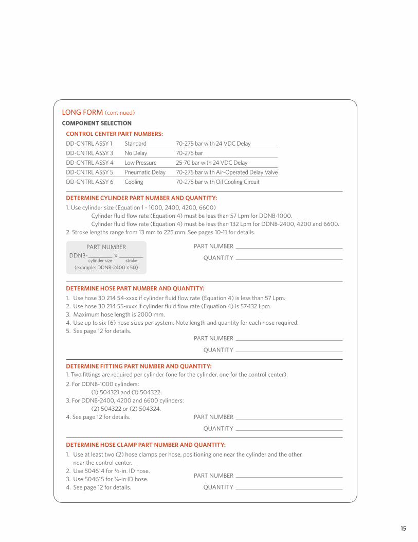
COMPONENT SELECTION
CONTROL CENTER PART NUMBERS:
DD-CNTRL ASSY 1 Standard 70-275 bar with 24 VDC Delay
DD-CNTRL ASSY 3 No Delay 70-275 bar
DD-CNTRL ASSY 4 Low Pressure 25-70 bar with 24 VDC Delay
DD-CNTRL ASSY 5 Pneumatic Delay 70-275 bar with Air-Operated Delay Valve
DD-CNTRL ASSY 6 Cooling 70-275 bar with Oil Cooling Circuit
LONG FORM (continued)
DETERMINE HOSE CLAMP PART NUMBER AND QUANTITY:
1. Use at least two (2) hose clamps per hose, positioning one near the cylinder and the other near the control center.2. Use 504614 for ½-in. ID hose.3. Use 504615 for ¾-in ID hose.4. See page 12 for details.
PART NUMBER
QUANTITY
DETERMINE FITTING PART NUMBER AND QUANTITY:1. Two fittings are required per cylinder (one for the cylinder, one for the control center).
2. For DDNB-1000 cylinders: (1) 504321 and (1) 504322.3. For DDNB-2400, 4200 and 6600 cylinders: (2) 504322 or (2) 504324.4. See page 12 for details. PART NUMBER
QUANTITY
DETERMINE HOSE PART NUMBER AND QUANTITY:
1. Use hose 30 214 54-xxxx if cylinder fluid flow rate (Equation 4) is less than 57 Lpm.2. Use hose 30 214 55-xxxx if cylinder fluid flow rate (Equation 4) is 57-132 Lpm.3. Maximum hose length is 2000 mm.4. Use up to six (6) hose sizes per system. Note length and quantity for each hose required.5. See page 12 for details.
PART NUMBER
QUANTITY
DETERMINE CYLINDER PART NUMBER AND QUANTITY:
1. Use cylinder size (Equation 1 - 1000, 2400, 4200, 6600) Cylinder fluid flow rate (Equation 4) must be less than 57 Lpm for DDNB-1000. Cylinder fluid flow rate (Equation 4) must be less than 132 Lpm for DDNB-2400, 4200 and 6600. 2. Stroke lengths range from 13 mm to 225 mm. See pages 10-11 for details.
PART NUMBER
QUANTITY
PART NUMBER
(example: DDNB-2400 X 50)
DDNB- X cylinder size stroke
US HEADQUARTERS10367 Brecksville Road, Brecksville, OH 44141 USATel: 1-800-876-4976, 440-526-5900 Fax: [email protected] www.hysonproducts.com
CANADA975 Fraser Drive, Unit 14, Burlington, ONT L7L 4X8 CanadaTel: 905-331-1311 Fax: 905-331-1342
MEXICOAve. Carlos Salinas de Gortari, #1010 Ote, Col. Apodaca Centro, CP 66600 Apodaca, N.L. MexicoTel: 5281 8145-0570 Fax: 5281 8145-0571
CHINANitrogen Gas Products, Associated Spring (Tianjin) Co., Ltd., Building A, Minggang Industrial Park Hong Kong Street, Jinnan Economic Development Zone, Tianjin, China, Post Code 300350Tel: +86 22 2857 4310 Fax: + 86 22 2857 4316
KOREABarnes Korea Ltd, Zip Code 431-060, #1110. Sungjee Starwith, 954-6 Gwanyang-dong Dongan-KuAnyang-Si Gyeonggi-do Korea.Tel: +82 31 422 4591 Fax: +82 31 422 4593
©2011 Hyson Products DDB5MJuly2011