Embed Size (px)
DESCRIPTION
SHUMATECHDRO-550 Construction Guide
Citation preview
DRO-550 Construction Guide (rev. 2)
1
SHUMATECH DRO-550 Construction Guide
DRO-550 Construction Guide (rev. 2)
2
Revision History Revision Description
1 Original version 2 Added board rework step 9
Table of Contents Assemble the PCB .......................................................................................................................... 2
Step 1. Parts Inventory................................................................................................................ 2 Step 2. Visual Inspection ............................................................................................................ 4 Step 3. Electrical Test ................................................................................................................. 5 Step 4. Smoke Test ..................................................................................................................... 7 Step 5. Processor Test ................................................................................................................. 9 Step 6. Solder Headers................................................................................................................ 9 Step 7. Solder LED Displays .................................................................................................... 10 Step 8. Solder Piezo and Program Switch ................................................................................ 10 Step 9. Board Rework ............................................................................................................... 12 Step 10. Program Software and Troubleshoot .......................................................................... 12
Fabricate the Enclosure................................................................................................................. 13 Step 1. Machine the Front Panel .............................................................................................. 13 Step 2. Machine the Rear Panel ............................................................................................... 15 Step 3. Drill the USB Hole ...................................................................................................... 16 Step 4. Install the Standoffs ..................................................................................................... 17 Step 5. Install the Connectors .................................................................................................. 18 Step 6. Attach Overlay............................................................................................................. 20
Cables Construction...................................................................................................................... 20
Assemble the PCB
Step 1. Parts Inventory
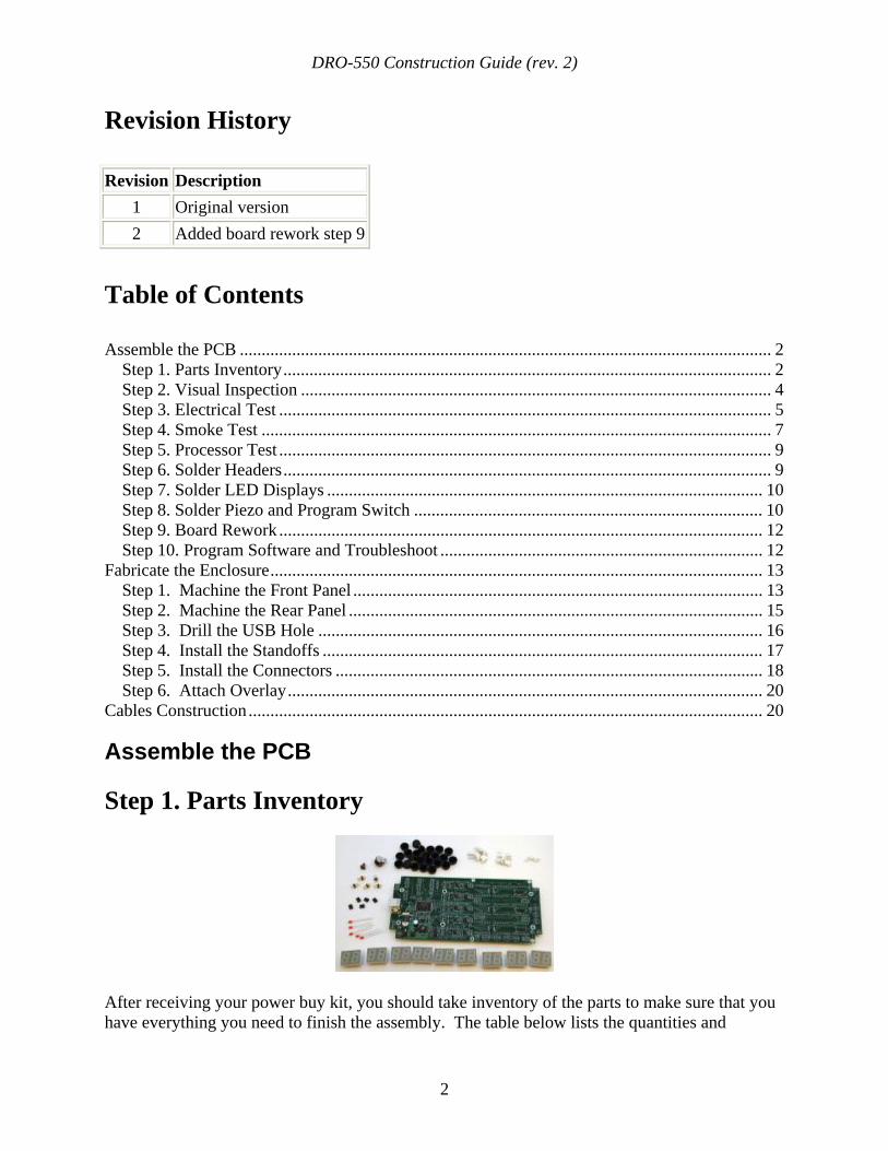
After receiving your power buy kit, you should take inventory of the parts to make sure that you have everything you need to finish the assembly. The table below lists the quantities and
DRO-550 Construction Guide (rev. 2)
3
descriptions of the parts in clockwise order on the picture at left starting from the the DRO-550 printed circuit board (PCB). You can click on this or any other picture to get a larger view of it.
Quantity Component 1 DRO-550 assembled circuit board 9 RED 7-segment LEDs 5 RED 3mm indicator LEDs 5 Shunt jumper 5 2x2 Header 1 Program tact switch 1 Piezo Buzzer 23 Black tact switch caps 5 4-pin MTA headers 5 3-pin MTA headers 2 2-pin MTA headers
You will also need some tools and supplies to finish assembling the circuit board. These supplies include:
• Soldering Iron - Just about any soldering iron will do but make sure it has a fairly fine point.
• Solder - 63/37 or 60/40 flux core solder with a diameter between 0.015" and 0.030" is best. You can use lead free solder but it is a more difficult to work with. You can also use larger diameter solder in a pinch but it is harder to control the amount of solder applied with larger diameters.
• Solder Wick - We all make mistakes and you'll want to have some of this handy stuff available when your soldering goes awry. Solder wick is a wire braid impregnated with flux that, when pressed against a solder connection with a soldering iron, wicks the solder up into braid. It is invaluable for desoldering a bad connection or removing excess solder.
• Antistatic Wrist Strap - Since we are working with static sensitive components, you should wear an antistatic wrist strap at all times while handling the boards and components. You should also try to work in a non-carpeted area that is as free from static as possible.
• Flux - This is not strictly needed since solder already contains flux, but it is sometimes handy to apply extra flux directly to a stubborn or dirty connection. Rosin flux is the most popular type but there are a variety of other formulations available including "no clean" types. If you get too much flux on the board, it is best to clean it off with a Q-tip dipped in rubbing alcohol because some types of flux can be corrosive.
• Magnifying Glass - Let's face it, modern electronic components are small and can be difficult to see with the naked eye. A magnifying glass will not only help you inspect your soldering work, but it will also help when we visually inspect the board.
• Multimeter - You will need a multimeter for testing and troubleshooting the board. Just about any multimeter will do and you will only need the DC voltage and resistance measurements.
DRO-550 Construction Guide (rev. 2)
4
Step 2. Visual Inspection The DRO-550 circuit board is professionally manufactured on a modern, surface mount assembly line. To keep the power buy price as low as possible, the boards are not electrically tested after they are assembled so there is a possibility that the board has an undetected flaw. The incidence of these flaws should be very low but it only takes a few minutes to check for the most likely failure points before applying power and doing permanent damage to the board.
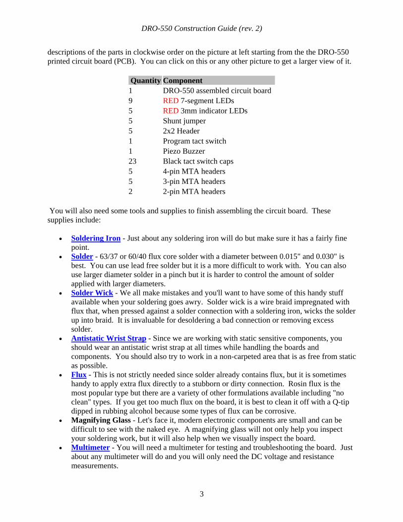
First, we visually inspect the power supply for components installed with an incorrect orientation. Reference the picture on the left. The red arrows point out the orientation marks for components that must be placed on the board in a certain way. The orientation marks are small lines or dots that are marked on the components. There are also small white dots on the printed circuit board that indicate the correct position of the orientation marks with respect to the board. For each red arrow in the picture, make sure that the component's orientation mark exactly matches the position as shown in the picture.
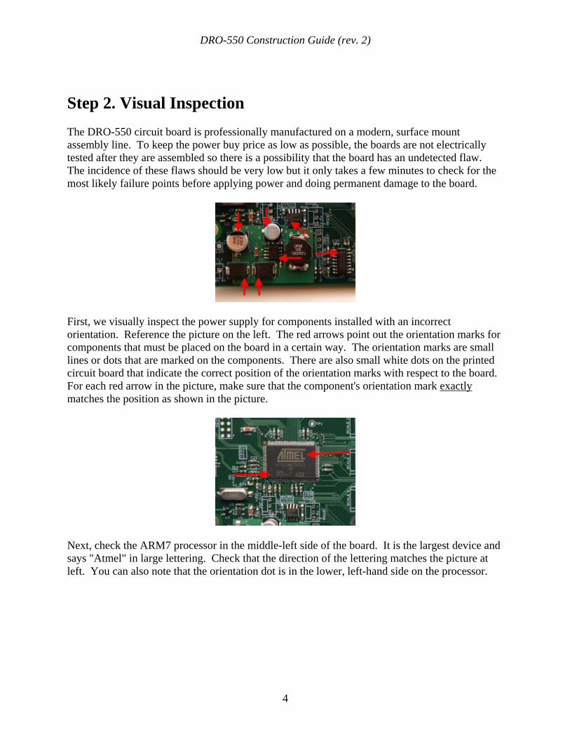
Next, check the ARM7 processor in the middle-left side of the board. It is the largest device and says "Atmel" in large lettering. Check that the direction of the lettering matches the picture at left. You can also note that the orientation dot is in the lower, left-hand side on the processor.
DRO-550 Construction Guide (rev. 2)
5
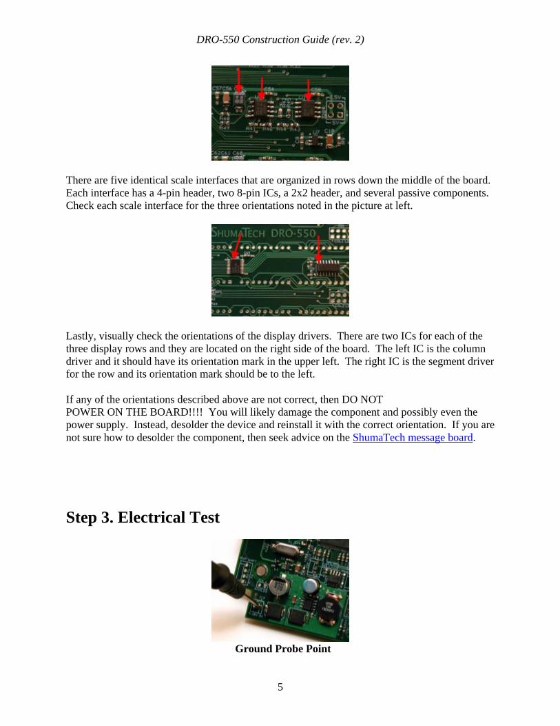
There are five identical scale interfaces that are organized in rows down the middle of the board. Each interface has a 4-pin header, two 8-pin ICs, a 2x2 header, and several passive components. Check each scale interface for the three orientations noted in the picture at left.
Lastly, visually check the orientations of the display drivers. There are two ICs for each of the three display rows and they are located on the right side of the board. The left IC is the column driver and it should have its orientation mark in the upper left. The right IC is the segment driver for the row and its orientation mark should be to the left.
If any of the orientations described above are not correct, then DO NOT POWER ON THE BOARD!!!! You will likely damage the component and possibly even the power supply. Instead, desolder the device and reinstall it with the correct orientation. If you are not sure how to desolder the component, then seek advice on the ShumaTech message board.
Step 3. Electrical Test
Ground Probe Point
DRO-550 Construction Guide (rev. 2)
6
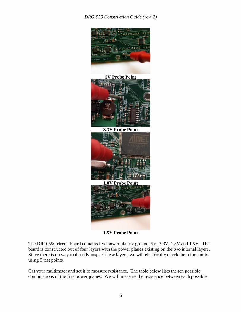
5V Probe Point
3.3V Probe Point
1.8V Probe Point
1.5V Probe Point
The DRO-550 circuit board contains five power planes: ground, 5V, 3.3V, 1.8V and 1.5V. The board is constructed out of four layers with the power planes existing on the two internal layers. Since there is no way to directly inspect these layers, we will electrically check them for shorts using 5 test points.
Get your multimeter and set it to measure resistance. The table below lists the ten possible combinations of the five power planes. We will measure the resistance between each possible
DRO-550 Construction Guide (rev. 2)
7
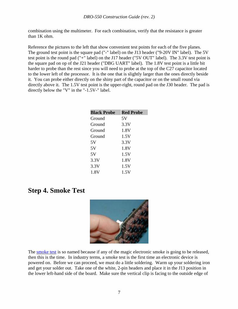
combination using the multimeter. For each combination, verify that the resistance is greater than 1K ohm.
Reference the pictures to the left that show convenient test points for each of the five planes. The ground test point is the square pad ("-" label) on the J13 header ("9-20V IN" label). The 5V test point is the round pad ("+" label) on the J17 header ("5V OUT" label). The 3.3V test point is the square pad on op of the J21 header ("DBG UART" label). The 1.8V test point is a little bit harder to probe than the rest since you will need to probe at the top of the C27 capacitor located to the lower left of the processor. It is the one that is slightly larger than the ones directly beside it. You can probe either directly on the shiny part of the capacitor or on the small round via directly above it. The 1.5V test point is the upper-right, round pad on the J30 header. The pad is directly below the "V" in the "-1.5V-" label.
Black Probe Red Probe Ground 5V Ground 3.3V Ground 1.8V Ground 1.5V 5V 3.3V 5V 1.8V 5V 1.5V 3.3V 1.8V 3.3V 1.5V 1.8V 1.5V
Step 4. Smoke Test
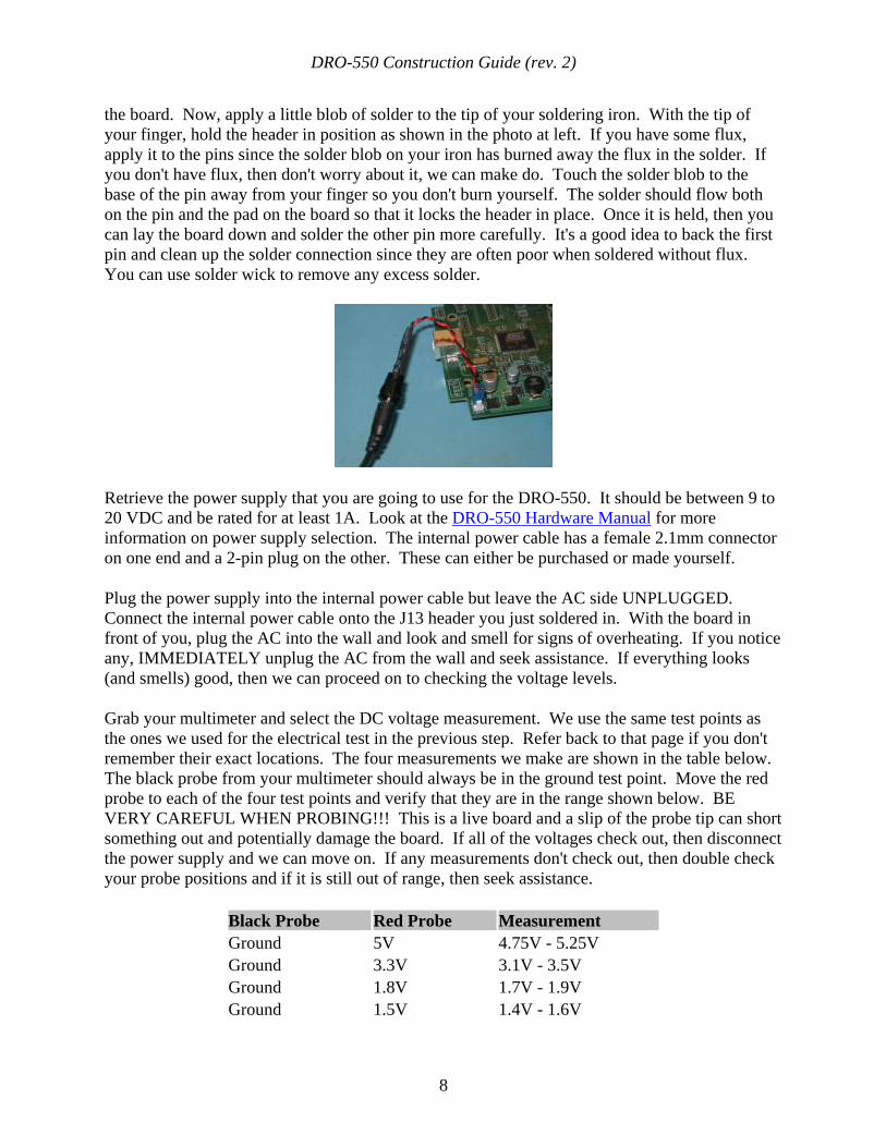
The smoke test is so named because if any of the magic electronic smoke is going to be released, then this is the time. In industry terms, a smoke test is the first time an electronic device is powered on. Before we can proceed, we must do a little soldering. Warm up your soldering iron and get your solder out. Take one of the white, 2-pin headers and place it in the J13 position in the lower left-hand side of the board. Make sure the vertical clip is facing to the outside edge of
DRO-550 Construction Guide (rev. 2)
8
the board. Now, apply a little blob of solder to the tip of your soldering iron. With the tip of your finger, hold the header in position as shown in the photo at left. If you have some flux, apply it to the pins since the solder blob on your iron has burned away the flux in the solder. If you don't have flux, then don't worry about it, we can make do. Touch the solder blob to the base of the pin away from your finger so you don't burn yourself. The solder should flow both on the pin and the pad on the board so that it locks the header in place. Once it is held, then you can lay the board down and solder the other pin more carefully. It's a good idea to back the first pin and clean up the solder connection since they are often poor when soldered without flux. You can use solder wick to remove any excess solder.
Retrieve the power supply that you are going to use for the DRO-550. It should be between 9 to 20 VDC and be rated for at least 1A. Look at the DRO-550 Hardware Manual for more information on power supply selection. The internal power cable has a female 2.1mm connector on one end and a 2-pin plug on the other. These can either be purchased or made yourself.
Plug the power supply into the internal power cable but leave the AC side UNPLUGGED. Connect the internal power cable onto the J13 header you just soldered in. With the board in front of you, plug the AC into the wall and look and smell for signs of overheating. If you notice any, IMMEDIATELY unplug the AC from the wall and seek assistance. If everything looks (and smells) good, then we can proceed on to checking the voltage levels.
Grab your multimeter and select the DC voltage measurement. We use the same test points as the ones we used for the electrical test in the previous step. Refer back to that page if you don't remember their exact locations. The four measurements we make are shown in the table below. The black probe from your multimeter should always be in the ground test point. Move the red probe to each of the four test points and verify that they are in the range shown below. BE VERY CAREFUL WHEN PROBING!!! This is a live board and a slip of the probe tip can short something out and potentially damage the board. If all of the voltages check out, then disconnect the power supply and we can move on. If any measurements don't check out, then double check your probe positions and if it is still out of range, then seek assistance.
Black Probe Red Probe Measurement Ground 5V 4.75V - 5.25V Ground 3.3V 3.1V - 3.5V Ground 1.8V 1.7V - 1.9V Ground 1.5V 1.4V - 1.6V
DRO-550 Construction Guide (rev. 2)
9
Step 5. Processor Test The next step is to verify that the ARM7 processor is functioning properly by plugging it into a PC. Install SAM-BA on your Windows PC as documented in Step 2 on the DRO-550 software page. You can also use a Linux machine but the instructions presented here are specific to Windows. After installation, plug one end of a Type B USB cable into your PC and the other end the USB connector on the left side of the DRO-550 board. Your PC should recognize the DRO-550 and you will get the standard Windows "Found New Hardware Wizard" dialog box. Select the option to "Install the software automatically" and press the Next> button. After a few seconds, the wizard should report that it is finished and you can press the Finsh button to close the dialog. If your Windows PC shows a balloon that says that the USB device is invalid or in not functioning properly, then there could be a problem with your processor and you should seek assistance. When the SAM-BA dialog box comes up, press cancel to close it. We will program the software into the DRO-550 later after we finish assembly of the DRO-550.
Step 6. Solder Headers
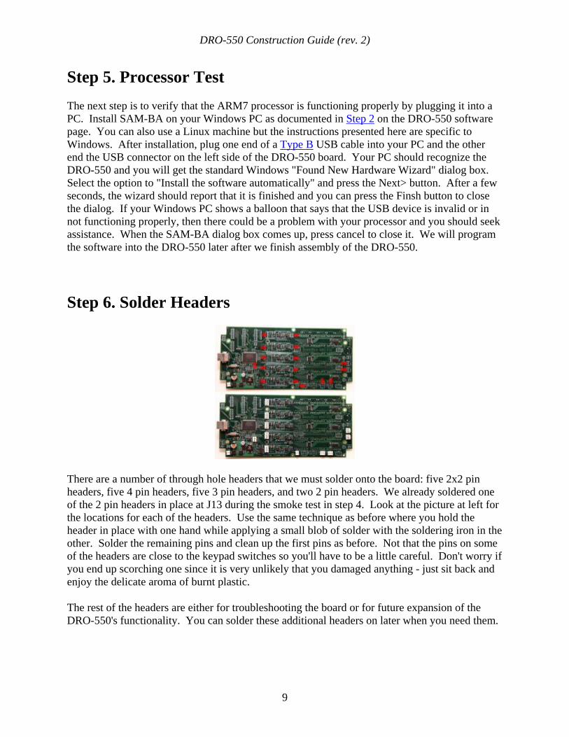
There are a number of through hole headers that we must solder onto the board: five 2x2 pin headers, five 4 pin headers, five 3 pin headers, and two 2 pin headers. We already soldered one of the 2 pin headers in place at J13 during the smoke test in step 4. Look at the picture at left for the locations for each of the headers. Use the same technique as before where you hold the header in place with one hand while applying a small blob of solder with the soldering iron in the other. Solder the remaining pins and clean up the first pins as before. Not that the pins on some of the headers are close to the keypad switches so you'll have to be a little careful. Don't worry if you end up scorching one since it is very unlikely that you damaged anything - just sit back and enjoy the delicate aroma of burnt plastic.
The rest of the headers are either for troubleshooting the board or for future expansion of the DRO-550's functionality. You can solder these additional headers on later when you need them.
DRO-550 Construction Guide (rev. 2)
10
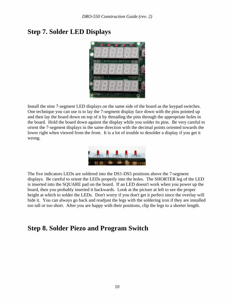
Step 7. Solder LED Displays
Install the nine 7-segment LED displays on the same side of the board as the keypad switches. One technique you can use is to lay the 7-segment display face down with the pins pointed up and then lay the board down on top of it by threading the pins through the appropriate holes in the board. Hold the board down against the display while you solder its pins. Be very careful to orient the 7-segment displays in the same direction with the decimal points oriented towards the lower right when viewed from the front. It is a lot of trouble to desolder a display if you get it wrong.
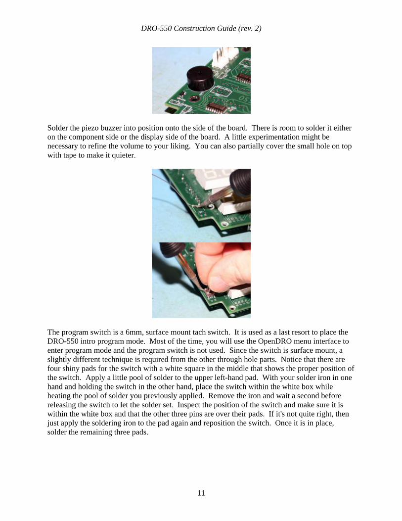
The five indicators LEDs are soldered into the DS1-DS5 positions above the 7-segment displays. Be careful to orient the LEDs properly into the holes. The SHORTER leg of the LED is inserted into the SQUARE pad on the board. If an LED doesn't work when you power up the board, then you probably inserted it backwards. Look at the picture at left to see the proper height at which to solder the LEDs. Don't worry if you don't get it perfect since the overlay will hide it. You can always go back and readjust the legs with the soldering iron if they are installed too tall or too short. After you are happy with their positions, clip the legs to a shorter length.
Step 8. Solder Piezo and Program Switch
DRO-550 Construction Guide (rev. 2)
11
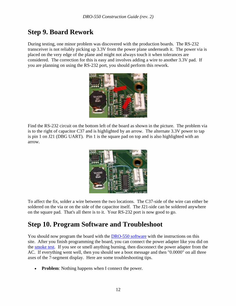
Solder the piezo buzzer into position onto the side of the board. There is room to solder it either on the component side or the display side of the board. A little experimentation might be necessary to refine the volume to your liking. You can also partially cover the small hole on top with tape to make it quieter.
The program switch is a 6mm, surface mount tach switch. It is used as a last resort to place the DRO-550 intro program mode. Most of the time, you will use the OpenDRO menu interface to enter program mode and the program switch is not used. Since the switch is surface mount, a slightly different technique is required from the other through hole parts. Notice that there are four shiny pads for the switch with a white square in the middle that shows the proper position of the switch. Apply a little pool of solder to the upper left-hand pad. With your solder iron in one hand and holding the switch in the other hand, place the switch within the white box while heating the pool of solder you previously applied. Remove the iron and wait a second before releasing the switch to let the solder set. Inspect the position of the switch and make sure it is within the white box and that the other three pins are over their pads. If it's not quite right, then just apply the soldering iron to the pad again and reposition the switch. Once it is in place, solder the remaining three pads.
DRO-550 Construction Guide (rev. 2)
12
Step 9. Board Rework During testing, one minor problem was discovered with the production boards. The RS-232 transceiver is not reliably picking up 3.3V from the power plane underneath it. The power via is placed on the very edge of the plane and might not always touch it when tolerances are considered. The correction for this is easy and involves adding a wire to another 3.3V pad. If you are planning on using the RS-232 port, you should perform this rework.
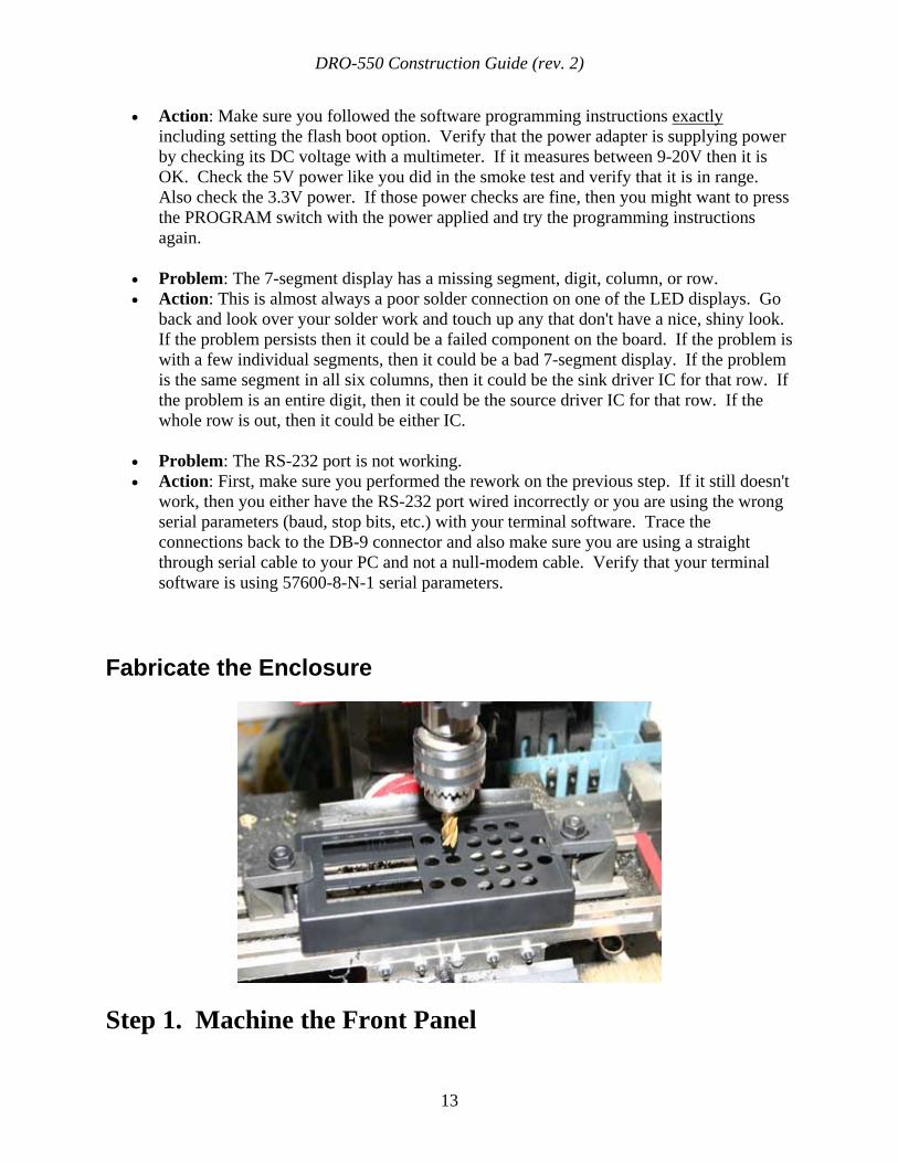
Find the RS-232 circuit on the bottom left of the board as shown in the picture. The problem via is to the right of capacitor C37 and is highlighted by an arrow. The alternate 3.3V power to tap is pin 1 on J21 (DBG UART). Pin 1 is the square pad on top and is also highlighted with an arrow.
To affect the fix, solder a wire between the two locations. The C37-side of the wire can either be soldered on the via or on the side of the capacitor itself. The J21-side can be soldered anywhere on the square pad. That's all there is to it. Your RS-232 port is now good to go.
Step 10. Program Software and Troubleshoot You should now program the board with the DRO-550 software with the instructions on this site. After you finish programming the board, you can connect the power adapter like you did on the smoke test. If you see or smell anything burning, then disconnect the power adapter from the AC. If everything went well, then you should see a boot message and then "0.0000" on all three axes of the 7-segment display. Here are some troubleshooting tips.
• Problem: Nothing happens when I connect the power.
DRO-550 Construction Guide (rev. 2)
13
• Action: Make sure you followed the software programming instructions exactly including setting the flash boot option. Verify that the power adapter is supplying power by checking its DC voltage with a multimeter. If it measures between 9-20V then it is OK. Check the 5V power like you did in the smoke test and verify that it is in range. Also check the 3.3V power. If those power checks are fine, then you might want to press the PROGRAM switch with the power applied and try the programming instructions again.
• Problem: The 7-segment display has a missing segment, digit, column, or row. • Action: This is almost always a poor solder connection on one of the LED displays. Go
back and look over your solder work and touch up any that don't have a nice, shiny look. If the problem persists then it could be a failed component on the board. If the problem is with a few individual segments, then it could be a bad 7-segment display. If the problem is the same segment in all six columns, then it could be the sink driver IC for that row. If the problem is an entire digit, then it could be the source driver IC for that row. If the whole row is out, then it could be either IC.
• Problem: The RS-232 port is not working. • Action: First, make sure you performed the rework on the previous step. If it still doesn't
work, then you either have the RS-232 port wired incorrectly or you are using the wrong serial parameters (baud, stop bits, etc.) with your terminal software. Trace the connections back to the DB-9 connector and also make sure you are using a straight through serial cable to your PC and not a null-modem cable. Verify that your terminal software is using 57600-8-N-1 serial parameters.
Fabricate the Enclosure
Step 1. Machine the Front Panel
DRO-550 Construction Guide (rev. 2)
14
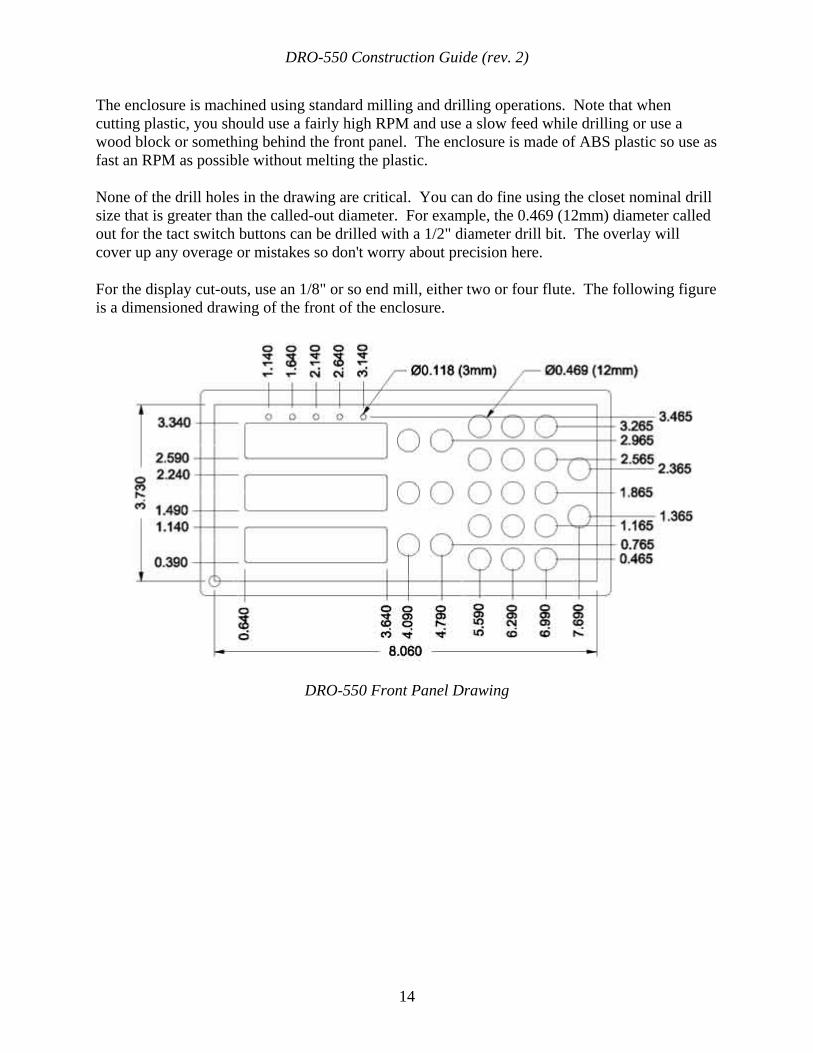
The enclosure is machined using standard milling and drilling operations. Note that when cutting plastic, you should use a fairly high RPM and use a slow feed while drilling or use a wood block or something behind the front panel. The enclosure is made of ABS plastic so use as fast an RPM as possible without melting the plastic.
None of the drill holes in the drawing are critical. You can do fine using the closet nominal drill size that is greater than the called-out diameter. For example, the 0.469 (12mm) diameter called out for the tact switch buttons can be drilled with a 1/2" diameter drill bit. The overlay will cover up any overage or mistakes so don't worry about precision here.
For the display cut-outs, use an 1/8" or so end mill, either two or four flute. The following figure is a dimensioned drawing of the front of the enclosure.
DRO-550 Front Panel Drawing
DRO-550 Construction Guide (rev. 2)
15
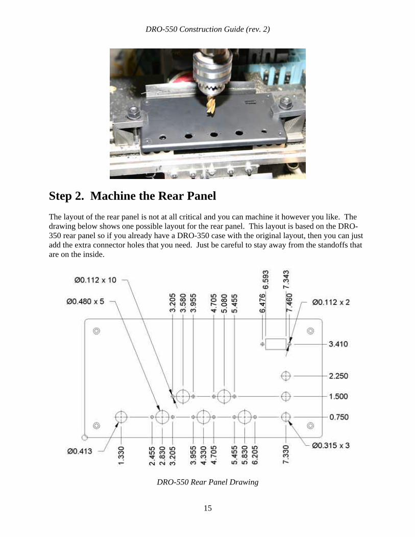
Step 2. Machine the Rear Panel The layout of the rear panel is not at all critical and you can machine it however you like. The drawing below shows one possible layout for the rear panel. This layout is based on the DRO-350 rear panel so if you already have a DRO-350 case with the original layout, then you can just add the extra connector holes that you need. Just be careful to stay away from the standoffs that are on the inside.
DRO-550 Rear Panel Drawing
DRO-550 Construction Guide (rev. 2)
16
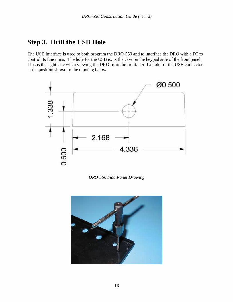
Step 3. Drill the USB Hole The USB interface is used to both program the DRO-550 and to interface the DRO with a PC to control its functions. The hole for the USB exits the case on the keypad side of the front panel. This is the right side when viewing the DRO from the front. Drill a hole for the USB connector at the position shown in the drawing below.
DRO-550 Side Panel Drawing
DRO-550 Construction Guide (rev. 2)
17
Step 4. Install the Standoffs The standoffs are mounted to the back panel of the enclosure and attach to the component side of the PCB with the seven segment displays and tact switches facing out. The six plastic posts in the back panel must be tapped 6-32 to hold the standoffs. You should use a small hand tap with a gentle touch. Be careful to stop as soon as the front of the tap hits the bottom of the post hole otherwise you will strip the threads. If you do, don't worry since you can just epoxy the standoffs in place just as well.
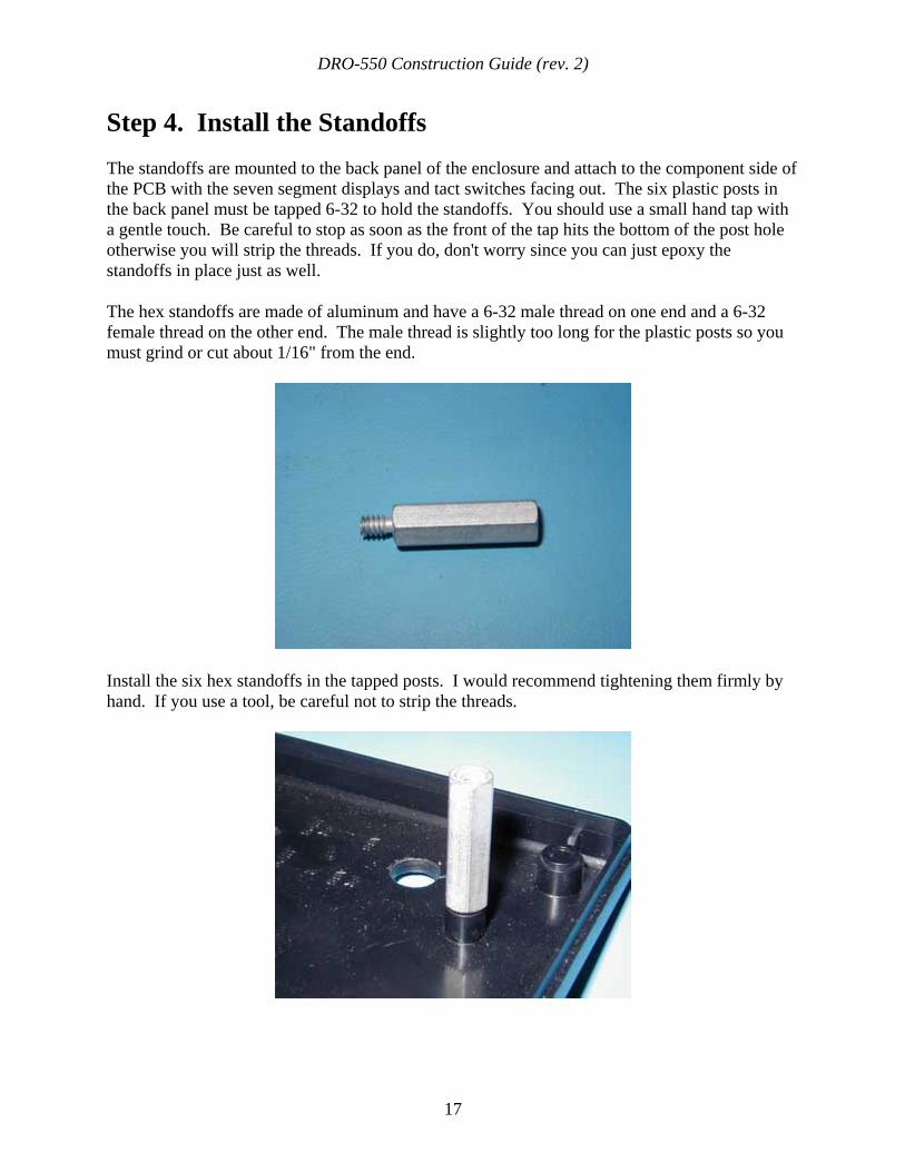
The hex standoffs are made of aluminum and have a 6-32 male thread on one end and a 6-32 female thread on the other end. The male thread is slightly too long for the plastic posts so you must grind or cut about 1/16" from the end.
Install the six hex standoffs in the tapped posts. I would recommend tightening them firmly by hand. If you use a tool, be careful not to strip the threads.
DRO-550 Construction Guide (rev. 2)
18
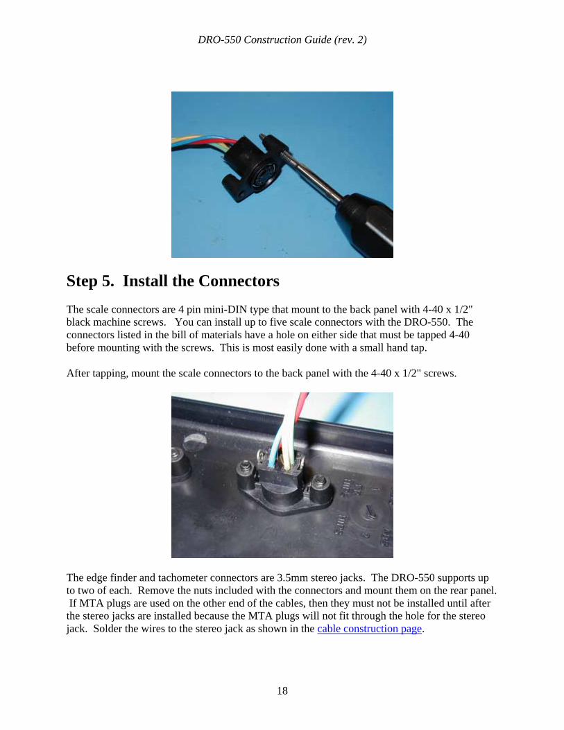
Step 5. Install the Connectors The scale connectors are 4 pin mini-DIN type that mount to the back panel with 4-40 x 1/2" black machine screws. You can install up to five scale connectors with the DRO-550. The connectors listed in the bill of materials have a hole on either side that must be tapped 4-40 before mounting with the screws. This is most easily done with a small hand tap.
After tapping, mount the scale connectors to the back panel with the 4-40 x 1/2" screws.
The edge finder and tachometer connectors are 3.5mm stereo jacks. The DRO-550 supports up to two of each. Remove the nuts included with the connectors and mount them on the rear panel. If MTA plugs are used on the other end of the cables, then they must not be installed until after the stereo jacks are installed because the MTA plugs will not fit through the hole for the stereo jack. Solder the wires to the stereo jack as shown in the cable construction page.
DRO-550 Construction Guide (rev. 2)
19
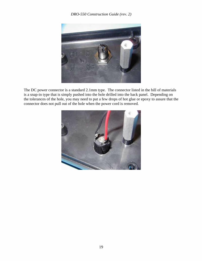
The DC power connector is a standard 2.1mm type. The connector listed in the bill of materials is a snap-in type that is simply pushed into the hole drilled into the back panel. Depending on the tolerances of the hole, you may need to put a few drops of hot glue or epoxy to assure that the connector does not pull out of the hole when the power cord is removed.
DRO-550 Construction Guide (rev. 2)
20
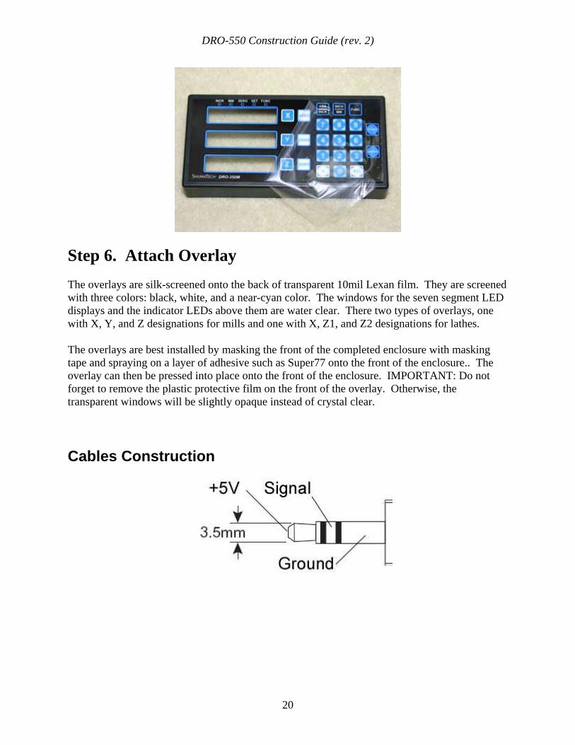
Step 6. Attach Overlay The overlays are silk-screened onto the back of transparent 10mil Lexan film. They are screened with three colors: black, white, and a near-cyan color. The windows for the seven segment LED displays and the indicator LEDs above them are water clear. There two types of overlays, one with X, Y, and Z designations for mills and one with X, Z1, and Z2 designations for lathes.
The overlays are best installed by masking the front of the completed enclosure with masking tape and spraying on a layer of adhesive such as Super77 onto the front of the enclosure.. The overlay can then be pressed into place onto the front of the enclosure. IMPORTANT: Do not forget to remove the plastic protective film on the front of the overlay. Otherwise, the transparent windows will be slightly opaque instead of crystal clear.
Cables Construction
DRO-550 Construction Guide (rev. 2)
21
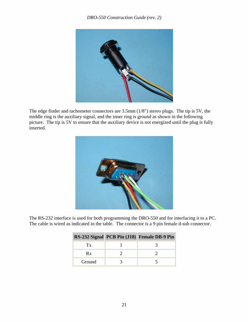
The edge finder and tachometer connectors are 3.5mm (1/8") stereo plugs. The tip is 5V, the middle ring is the auxiliary signal, and the inner ring is ground as shown in the following picture. The tip is 5V to ensure that the auxiliary device is not energized until the plug is fully inserted.
The RS-232 interface is used for both programming the DRO-550 and for interfacing it to a PC. The cable is wired as indicated in the table. The connector is a 9 pin female d-sub connector.
RS-232 Signal PCB Pin (J18) Female DB-9 Pin
Tx 1 3
Rx 2 2
Ground 3 5
DRO-550 Construction Guide (rev. 2)
22
If you can handle basic soldering, it is easy to build cables for the Chinese scales yourself. In some respects, I would almost recommend it over buying the commercial cables. The big problem with the commercial cables is that the end that plugs into the scale is poorly designed. It can be difficult to get a good connection without a lot of fidgeting with the connector. Also, the connector sometimes has a tendency to short across the pads which will either prevent the DRO-550 from reading the scale or even cause the DRO-550 to shut down power to the scales if the positive supply is shorted.
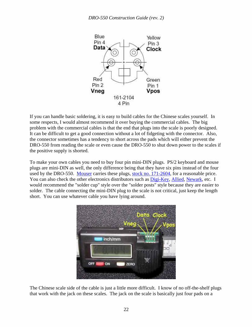
To make your own cables you need to buy four pin mini-DIN plugs. PS/2 keyboard and mouse plugs are mini-DIN as well, the only difference being that they have six pins instead of the four used by the DRO-550. Mouser carries these plugs, stock no. 171-2604, for a reasonable price. You can also check the other electronics distributors such as Digi-Key, Allied, Newark, etc. I would recommend the "solder cup" style over the "solder posts" style because they are easier to solder. The cable connecting the mini-DIN plug to the scale is not critical, just keep the length short. You can use whatever cable you have lying around.
The Chinese scale side of the cable is just a little more difficult. I know of no off-the-shelf plugs that work with the jack on these scales. The jack on the scale is basically just four pads on a
DRO-550 Construction Guide (rev. 2)
23
PCB. Even if the plugs were available, I would still recommend you do the following to get a solid, reliable connection.
What I recommend is to solder the four wires from the cable directly onto the pads on the scale. Start by tinning the four pads with solder. You don't want a big puddle of solder but you do want enough to make a solid connection to the wire on the cables. Next, strip the end of each wire and attach it to each pad by holding the wire against the pad with one hand and touching the pad with the solder iron with the other hand. Look at the diagram of the scale jack below to figure out which wire to solder to which pad. The most important thing here is to hold the wire and scale as steady as possible so that you get a good, strong solder joint.