Embed Size (px)
Citation preview

Roof Downspout Controls Design Guide Page 1 of 15
DESIGN GUIDE NO. 5
ROOF DOWNSPOUT RUNOFF CONTROLS 2009 DRAINAGE DESIGN AND EROSION CONTROL MANUAL
Thurston County, Washington
T. Pat Allen, P.E., Senior Engineer, Drainage Manual Thurston County Water Resources Division
Resource Stewardship Department February 4, 2010 (Revised 1/24/11)
Purpose The purpose of this Design Guide is to summarize in one location the requirements for managing stormwater from roof downspouts (Minimum Requirement #5 and BMPs LID.04 and LID.05) using the 2009 Drainage Design and Erosion Control Manual for Thurston County (DDECM). This Design Guide does not address the use of Green Roofs, Rainwater Harvesting (Cisterns) or Bioretention facilities (rain gardens) for managing downspout runoff. Roof downspout runoff control requirements and applications are found in several locations within the DDECM including:
Volume I, Section 2.4.6, Minimum Requirement #5: Onsite Stormwater Management Volume I, Section 3.5.2, Abbreviated Drainage Plan: Conditions Volume I, Section 4.2.3, Step by Step BMP Selection Process: Step 3: Implement
LID BMPs as Required and to the Maximum Extent Practicable Volume I, Appendix G, Standard Stormwater Notes. Volume III, Section 2.3.4, Determine Design Infiltration Rate Volume III, Section 3.6.2, Access to Conveyance Systems Volume III, Section 3.7.3, Pipe Materials Volume III, Section 3.11.1, Private Drainage Systems: Discharge Locations Volume III, Section 3.11.2, Private Drainage Systems: Drainage Stub-outs Volume IV, Section A7.9, Roof and Building Drains at Manufacturing and Commercial
Buildings. Volume V, Section 2.2.1, LID.04 Downspout Infiltration Systems Volume V, Section 2.2.2, LID.05 Downspout Dispersion Systems Volume V, Section 2.2.3, LID.06 Sheet Flow Dispersion Volume V, Section 2.2.5, LID.08 Bioretention Facilities Volume V, Section 2.2.7, LID.10 Vegetated Roofs Volume V, Section 2.2.8, LID.11 Full Dispersion Volume V, Appendix V-B, Facility Liners and Geotextiles Volume V, Appendix V-E, Site Design Elements
In addition to references in the 2009 DDECM, the Washington State Department of Ecology 2005 Stormwater Management Manual for Western Washington provides additional information related to roof downspout controls that is incorporated into this Design Guide. Attached to this Design Guide are details of infiltration trenches, drywells, splash blocks and dispersion trenches derived from the 2009 DDECM.
Applicability Minimum Requirement #5, Onsite Stormwater Management, requires projects to employ onsite stormwater management BMPs to infiltrate, disperse, and retain stormwater runoff
Roof Downspout Controls Design Guide Page 2 of 15
onsite to the maximum extent feasible. All projects required to comply with Minimum Requirement #5 shall manage roof downspout runoff through one of the following methods to be considered in descending order of preference: 1st Downspout infiltration systems (BMP LID.04) or Bioretention (BMP LID.08) 2nd Downspout dispersion systems (BMP LID.05) – only if infiltration is not feasible 3rd Collect and convey to the County or private stormwater system – only if other
alternatives are not feasible. Other alternatives for managing roof runoff include the use of Green Roofs and Rainwater Harvesting (Cisterns or Rain Barrels). These special cases are not discussed in this Design Guide. The 2005 Ecology Stormwater Manual allows for perforated stub-outs for downspout drains; however, this is not allowed by Thurston County. Minimum Requirement #5 and downspout controls are required for projects that:
1. Create 2,000 square feet or more of new impervious surface; or. 2. Have 7,000 square feet or more of land disturbing activity.
For smaller projects, on-site measures, including downspout controls shall be implemented to the maximum extent practicable. Redevelopment projects that meet criteria requiring retrofitting the existing site to current stormwater standards would be required to implement downspout controls in accordance with the 2009 DDECM standards for existing structures. Reference: DDECM, Volume I, 2.3 Applying Minimum Requirements & 2.4.6 Minimum Requirement #5, Onsite Stormwater Management.
Benefits of Downspout Control of Stormwater Runoff from most roof surfaces is relatively clean and does not require water quality treatment. By managing this stormwater separately through infiltration or dispersion the impact from development on stormwater discharge volumes and flow rates can be mitigated and the size of treatment and flow control facilities can be reduced. If roof runoff is infiltrated or dispersed in accordance with the requirements of the 2009 DDECM the roof area can be discounted from the project area impervious surface totals for purposes of sizing stormwater facilities and determining effective impervious area thresholds of Minimum Requirement #7 (Flow Control). Downspouts infiltrated in accordance with the requirements of the 2009 DDECM are considered “non-effective” impervious surface for purposes of applying BMP LID.11, Full Dispersion, and do not count against the impervious surface limits imposed in applying that BMP.
Special Requirements
1. Infiltration trenches and drywells may be considered underground injection chambers (UIC) and may be subject to Department of Ecology registration

Roof Downspout Controls Design Guide Page 3 of 15
requirements. Infiltration systems for single family residences only infiltrating clean roof runoff are currently exempt from UIC registration requirements.
2. Downspout infiltration systems may not be used to directly infiltrate runoff
from pollutant generating impervious surfaces, such as uncoated metal roofs. For commercial and industrial roofs, runoff from roof areas shall be subject to source control requirements of Volume IV of the DDECM (Section A7.9).
3. Downspout infiltration systems are not allowed within a Marine Bluff Hazard
Area or Landslide Hazard Area (and its buffer) as defined in Thurston County Code, Title 17 without special acceptance by Thurston County.
Design This section describes the design procedures for downspout stormwater control including downspout infiltration, downspout dispersion, and connection to the stormwater system. Downspout infiltration is required unless it is not feasible. Circumstances when downspout infiltration may not be feasible include:
Soils are NRCS category C or D with an estimated design infiltration rate of less than approximately 0.3 inches/hour.
The depth from the existing ground surface to seasonal high groundwater or
an impervious layer (i.e. till or bedrock) is less than 3-ft, or the depth from the base of a proposed drywell, infiltration trench, or bioretention facility serving less than 7,500 square feet of roof area to seasonal high groundwater or an impervious layer is less than 1-ft.
The infiltration facility cannot be located on the lot and meet setback
requirements to wells, drainfields, buildings, steep slopes, landslide hazard area, etc.
The infiltration facility cannot be located on the lot and meet the requirements
related to steep slopes. (i.e. located where slopes are flatter than 4H:1V and/or if slopes greater than 15% and 10-ft in height exist a geotechnical professional must provide a favorable evaluation of the impact on the slopes stability).
The infiltration facility cannot be located on the lot and meet the requirements
related to placement of infiltration facilities in fill soils. Requirements for infiltration facility placement in fill soils are:
o A measured infiltration rate of at least 8 inches per hour o Fill placement and compaction supervised by a geotechnical
engineer or professional civil engineer with geotechnical experience.
If downspout infiltration is not feasible, then downspout dispersion (BMP LID.05 or BMP LID.06) shall be provided where feasible. Circumstances when downspout dispersion may not be feasible include:
Downspout dispersion may create flooding or erosion of downstream properties.

Roof Downspout Controls Design Guide Page 4 of 15
There is insufficient dispersion area to meet minimum flow path lengths (50-ft for splash blocks, 25-ft for dispersion trench) to property boundaries, structures, critical areas, impervious surfaces or landslide hazard areas (and their buffers).
A proposed dispersion area is subject to saturated conditions or flooding.
The dispersion area cannot be permanently protected through a covenant or
easement (not required for residential project on single lot).
The point of dispersion is within 50 feet of the top of a slope of 15 percent or greater with a height of 10 feet without a geotechnical professional’s favorable evaluation of the impact on the slope.
The dispersion area cannot meet separation requirements to drainfields (i.e.
dispersion area must be located downslope of the primary and reserve drainfield area of an on-site septic system unless topography clearly prohibits flows from intersecting the drainfield).
If downspout infiltration or dispersion is not feasible, then downspouts shall be connected to the stormwater system for the project or plat or connect to the public stormwater system (ditch or storm sewer). A. Downspout Infiltration Systems Design Process The following generalized design process is suggested for downspout infiltration systems:
1. Evaluate project site for suitability including area available, slopes, depth to bedrock, presence of wetlands, depth to water table, etc. If downspout infiltration is feasible for the site proceed with the design process.
2. Identify the location of all roof downspouts associated with the building, review
architectural plans, or consult with architect/designer on downspout locations.
3. Choose between infiltration trench, drywell, or bioretention (rain garden) facility for managing roof runoff from each downspout.
4. Calculate the contributing roof area to each downspout infiltration facility. If
contributing area is less than 7,500 square feet, the soils are classified as “outwash” (NRCS Type A or B) by a soils professional, and the project is either a single family residence or commercial development, then prescriptive sizing methods for infiltration trenches and drywells may be used in lieu of calculating design infiltration rates. For drywells, the prescriptive method can only be used if the project is not subject to Minimum Requirement #7, Flow Control.
5. Conduct soils investigations as required in the area of the proposed infiltration
facility. If prescriptive methods are proposed, then the soils professional (including a septic designer) shall verify that soils are “outwash.” If design will not use the prescriptive methods, then conduct soil testing to establish a design infiltration rate per the procedures in Volume III, Chapter 2 of the 2009 DDECM.
6. For the prescriptive methods determine the required storage volume and the size
and number of drywells required or the required trench length based on the soils and contributing area. Layout the location of trenches or drywells on the site plan to meet setback, trench length, trench separation, drywell separation and other site requirements.

Roof Downspout Controls Design Guide Page 5 of 15
7. For non-prescriptive design, use the Western Washington Hydrologic Model, Version 3, (WWHM3) with Thurston County enhancements to model the infiltration system. Use the “Gravel Trench Bed” element and the design infiltration rate determined in step 5 to size the trench or drywell to infiltrate 100% of the influent flow file.
8. For bioretention design, see DDECM, Volume V, BMP LID.08, Bioretention
Facilities. Bioretention design is not addressed in this Design Guide.
9. If hydrologic modeling is required to demonstrate compliance with flow control (MR #7) and/or runoff treatment (MR#6) requirements, then use the WWHM3 and model the roof area that is infiltrated in outwash (A/B) soils using the “Basin” element and input the area of the roof as one of the following land types:
a. A/B/IMP INF/FLAT = Infiltration of impervious area runoff on A/B soil
with flat slope. b. A/B/IMP INF/MOD = Infiltration of impervious area runoff on A/B soil
with moderate slope. c. A/B/IMP INF/STEEP = Infiltration of impervious area runoff on A/B soil
with steep slope. If prescriptive methods were not used and an infiltration facility was designed using WWHM3, then include the facility in the WWHM3 model for the project site. This will ensure that credit for roof drain infiltration is accounted for in meeting minimum infiltration requirements for the project.
10. Layout infiltration facilities and downspout connections on drainage plans and be
sure to address all applicable design details such location, layout, structures, pipe size, type and slope, etc. Show design and maximum contributing roof area to each infiltration facility on site plans and construction drawings.
11. Provide details and specifications for yard drains or catch basins, piping,
geotextiles, structures, trench fill, etc.
12. Include all design calculations, assumptions, modeling parameters, etc. in the Drainage Report for the project.
Soils Investigation and Report Requirements If downspout infiltration is proposed, a geotechnical report or opinion is required to be submitted with the application. For small prescriptive designs this may be a simple letter report showing the location of test pits and an opinion as to the type of soil in the proposed infiltration facility location and documentation of estimated depth to seasonal high groundwater, a till layer or other restrictive layer (i.e. bedrock). In other cases the soils information will be more extensive.
A soils report must be prepared by a professional soil scientist certified by the
Soil Science Society of America (or an equivalent national program), a locally licensed onsite sewage designer, or by another suitably trained person working under the supervision of a professional engineer, geologist, hydrogeologist or engineering geologist registered in the State of Washington.
The soils report must reference a sufficient number of soil logs to establish
the type and limits of soils on the project site. The report should at a minimum identify the limits of any outwash type soils (i.e. those meeting USDA soil texture classes ranging from coarse sand and cobbles to loam) versus other types and include an inventory of topsoil depth.
Roof Downspout Controls Design Guide Page 6 of 15
If a design infiltration rate is used in lieu of the prescriptive method, excavate test pits or borings to a depth of at least 6 feet below the proposed base of the infiltration facility.
o Test pit or boring explorations shall be conducted during mid to
late in the wet season (December 1st through April 30th). o For infiltration trenches, there shall be one test pit or boring per
100 feet of trench length with a minimum of two required per trench, regardless of length.
o For small-scale facilities (contributing area less than 7,500
square feet), only one testing location is required.
For prescriptive designs at least one soils log at the location of the infiltration system shall be dug to a depth of at least 6-feet from proposed grade, identifying the SCS series of the soil and the USDA textural class of the soil horizon through the depth of the log, and noting any evidence of high groundwater level such as mottling.
Evaluation of the impact of infiltration facilities within 50-feet of slopes of 15
percent or greater and 10-feet in height or within 300-feet of geologic hazard areas.
Setback Requirements All infiltration facilities, including drywells and infiltration trenches for rood downspouts shall maintain minimum setback distances as follows: Horizontal Clearances
10 feet – from edge of infiltration facility to property lines and onsite structures
50 feet – from top of slopes steeper than 15 percent and greater than 10 feet
high. The Administrator or designee may require a geotechnical report to evaluate whether a slope exceeding 15 percent is a landslide hazard area. Increased setbacks or prohibition of infiltration facilities may result from this report. The geotechnical analysis and report shall address the potential impact of the facility on the slope. The geotechnical report may recommend a reduced setback, but in no case shall the setback be less than the vertical height of the slope.
10 feet – from edge of infiltration facility to building sewer
50 feet – from septic tank, holding tank, containment vessel, pump chamber,
and distribution box
100 feet – from edge of septic drainfield and drainfield reserve area.
100 feet – from drinking water wells and springs used for drinking water supplies.
300 feet – from landslide hazard area (as defined by Thurston County Code
Title 17.15.600 – Geologic Hazard Areas) unless the slope stability impacts of such systems have been analyzed and mitigated by a geotechnical

Roof Downspout Controls Design Guide Page 7 of 15
professional, and appropriate analysis indicates that the impacts are negligible.
100 feet – from building foundation or basement, where infiltration facilities
are located upgradient from building. The Project Engineer shall perform calculations to ensure that the line of saturation, measured from the design storm elevation in the facility, at a gradient acceptable to the Administrator or designee, falls a minimum of 1 foot below the lowest floor elevation. Setbacks shall be increased as necessary to allow for saturation effects.
20 feet – from building foundation or basement, where infiltration facilities
are located downgradient from building. The Project Engineer shall perform calculations to ensure that the line of saturation, measured from the design storm elevation in the facility, at a gradient acceptable to the Administrator or designee, falls a minimum of 1 foot below the lowest floor elevation. Setbacks shall be increased as necessary to allow for saturation effects.
Infiltration Trench Requirements
Prescriptive design methods are allowed for infiltration trenches if the
following criteria are met:
o Contributing drainage area is less than 7,500 square feet. o Property is a single family residential lot or commercial
development.
o Soils are characterized as outwash by a soil professional (including septic system designer).
o At least 3-feet of permeable soils exist from the proposed final
grade to the seasonal high groundwater table or an impermeable layer (i.e. till, bedrock).
o Trench design is per standard detail 2.1 or 2.2 of Volume V,
BMP LID.04, Downspout Infiltration Systems.
A prescriptive infiltration trench design was inadvertently left out of the 2009 DDECM. An applicant may use the Ecology prescriptive trench design contained within the 2005 Stormwater Management Manual for Western Washington as follows:
o The following minimum lengths (linear feet) per 1,000 square
feet of roof area based on soil type may be used for sizing downspout infiltration trenches:
Coarse sand and cobbles: 20 lineal feet Medium Sand: 30 lineal feet Fine sand, loamy sand: 75 lineal feet Sandy loam: 125 lineal feet Loam: 190 lineal feet
A structure with a sump shall be located upstream of the infiltration trench,
which provides a minimum of 12 inches of depth below the outlet riser. The outlet riser pipe bottom shall be designed to be submerged at all times, and a screening material shall be installed on the pipe outlet. (See Figure 2.1).

Roof Downspout Controls Design Guide Page 8 of 15
Maximum length of trench must not exceed 100 feet from the inlet sump.
An alternative trench design based on Figure 2.2 of Volume V, BMP LID.04 may be used where soils are course sands and gravels. In this design, there is no distribution pipe or geotextile filter fabric and the downspout discharges to the surface of the trench eliminating the need for a structure with a sump.
Aggregate for the infiltration trench shall be 3/4 to 1-1/2 inch washed round
rock. Minimum spacing between trench centerlines is 6-feet. Except that if the
infiltration target is the interflow zone then minimum spacing between trench centerlines is 25-feet. If hardpan is less than 6-feet below finished grade, or the trench is excavated to closer than 3 feet of hardpan (whatever the depth), then the target for infiltration is the interflow zone.
Trenches shall, as nearly as practical, follow a contour line.
Trenches shall be covered the same day they are opened.
Trenches shall be no wider than can be excavated by a backhoe straddling the
trench. Geotextile filter fabric shall be wrapped entirely around trench drain rock prior
to backfilling EXCEPT that a 6-inch layer of sand below the trench bottom may be used in lieu of a filter fabric liner on the bottom. Filter fabric shall be “Geotextile for Underground Drainage,” low survivability, Class C as described in Volume V of the DDECM, Appendix V-B, Facility Liners and Geotextiles.
Infiltration trenches may be placed in fill material that is placed and
compacted under the direct supervision of a geotechnical engineer or professional civil engineer with geotechnical expertise and the infiltration rate is at least 8 inches per hour. Infiltration rate determination shall be per the methods described in Volume III of the DDECM. Trench length in fill shall be 60 linear feet per 1,000 square feet of roof area for a prescriptive design.
Infiltration trenches may be located under pavement, if designed by a
professional engineer. Trenches must include an overflow at least 1 foot below the pavement, and be in a location that can accommodate overflow without creating a significant adverse impact to downhill properties or drainage systems. The trench depth must be measured from the overflow elevation, not the ground surface.
Infiltration Drywell Requirements
Figure 2.3 presents the design of a typical downspout infiltration drywell
system. The drywell shall include a catch basin or its equivalent upstream of the drywell.
Prescriptive design methods are allowed for infiltration drywells if the
following criteria are met:
o Project is not subject to Minimum Requirement #7 (Generally less than 5,000 square feet of new impervious surface and/or less than 3/4 acre of native vegetation converted to landscape, see Volume I, Chapter 2).

Roof Downspout Controls Design Guide Page 9 of 15
o Contributing drainage area is less than 7,500 square feet.
o Property is a single family residential lot or commercial development.
o Soils are characterized as outwash by a soils professional
(including septic system designer).
o At least 1-foot of permeable soil exists from the proposed drywell bottom to the seasonal high groundwater table or an impermeable layer (i.e. till or bedrock).
o Drywell design is per standard detail 2.3 of Volume V, BMP
LID.04, Downspout Infiltration Systems.
For a prescriptive infiltration drywell design provide a sufficient size and number of drywells to meet the following storage volume requirements (total volume, including rock backfill) per 1,000 square feet of roof area:
-NRCS Soil Type A or B, “Outwash,” (Sand, loamy sand, sandy loam, loam): 125 cubic feet
-NRCS Soil Type C (Silt loam, sandy clay loam,
“till soils” with Group or B surface horizon): 250 cubic feet
-NRCS Soil Type D (Silts, clays, rock outcroppings, “till” soils with Group C or D surface horizons) 750 cubic feet
Note: Drywells not recommended for Type C or D soils and should only be used if reasonable alternatives are infeasible.
If the criteria for a prescriptive design are not met then the applicant shall meet requirements for infiltration facilities and conduct soils testing per Volume III of the DDECM and design the drywell system using hydrologic modeling (WWHM3, with Thurston County Enhancements).
If a pipe or other open structure is provided, the required volume may be reduced proportionate to the area of the open structure. Calculate the volume reduction by dividing the volume of the open structure by the porosity of the rock backfill (typical value of 0.4).
Minimum separation between drywells shall be 4-feet. This is measured from
outside edge to outside edge, not from center to center.
Drywells shall be a minimum of 48 inches in diameter and 5 feet deep (4 feet of gravel and 1 foot of suitable cover material). A greater depth and diameter is allowed if other criteria area met.
Rock backfill for the drywell shall consist of 3/4 to 1-1/2 inch washed round
rock. A structure with a sump shall be located upstream of the drywell, which
provides a minimum of 12 inches of depth below the outlet riser. The outlet riser pipe bottom shall be designed to be submerged at all times, and a screening material shall be installed on the pipe outlet. (See Figure 2.3).
Geotextile filter fabric shall be wrapped over the top of the drain rock and on
drywell sides prior to backfilling. Filter fabric shall be “Geotextile for

Roof Downspout Controls Design Guide Page 10 of 15
Underground Drainage,” low survivability, Class C as described in Volume V of the DDECM, Appendix V-B, Facility Liners and Geotextiles.
Where individual lot drywells are to be installed in a residential subdivision,
the project engineer shall determine the required size of each drywell for each lot or group of lots with similar soils. The project engineer shall then record these sizes as necessary to ensure that they become restrictions for future building applications (e.g., record written conditions for lots and/or dictate drywell size on the face of the final plat mylar, etc.).
B. Downspout Dispersion Downspout dispersion systems are gravel-filled trenches or splash blocks that spread roof runoff over vegetated, pervious areas. Sheet flow dispersion applies when roof runoff is not collected in gutters but allowed to flow uniformly off the roof surface and disperse into vegetation downstream from the structure. Dispersion attenuates peak flows by slowing entry of runoff into the conveyance system, allowing some infiltration and providing some water quality benefits such as filtration and vegetative uptake. Limitations The use of dispersion for roof downspouts shall be limited to cases where no risk of flooding or erosion to downstream properties may result. The discharge point of dispersion systems shall be setback at least 50 feet from the top of a slope of 15 percent or greater with a height of 10 feet. A geotechnical analysis and report must be prepared addressing the potential impact of the facility on the slope. The geotechnical report may recommend a reduced setback, but in no case shall the setback be less than the vertical height of the slope. The Administrator or designee may require a geotechnical report to evaluate whether a slope exceeding 15 percent is a landslide hazard area. Increased setbacks or prohibition of dispersion facilities may result from this report. For sites with septic systems, the discharge point of any dispersion system must be downslope of the primary and reserve drainfield areas. This requirement may be waived if topography clearly prohibits flows from intersecting the drainfield. The vegetative flow path required for downspout dispersion is measured from the dispersion system discharge point to the downstream property line, stream, wetland, or other impervious surface. Flow path measurement may traverse a property line into an adjacent critical area buffer (except for steep slope buffers), provided that the critical area buffer is permanently protected through a covenant, easement, or tract dedicated as part of the proposed project. Design Process The following generalized design process is suggested for downspout dispersion systems:
1. Evaluate project site for suitability including area available, slopes, dispersion flow lengths, presence of wetlands, drainfield location, etc. If downspout dispersion is feasible for the site proceed with the design process.
2. Identify the location of all roof downspouts associated with the building, review
architectural plans, or consult with architect/designer on downspout locations. Establish the contributing roof area for each downspout.

Roof Downspout Controls Design Guide Page 11 of 15
3. Choose between dispersion trench, splash blocks, or sheet flow dispersion for each roof area contributing to a downspout. If contributing roof area is less than 700 square feet then either splash blocks or standard dispersion trench design is allowed. If greater than 700 square feet, then only a dispersion trench is allowed and the use of a gradeboard design is required.
4. For dispersion trenches calculate the trench length required by dividing the roof
area by 700 and then multiplying by a 10 to determine the required dispersion trench length. I.e. if roof area is 3200 square feet, then the required trench length is 3200/700x10 = 45.7 feet. Maximum trench length is 50-ft. If multiple trenches are required ensure that trench separation of 50-feet is met between trench dispersion systems.
5. Using a topographic site map locate the splash blocks, dispersion trenches, and
dispersion areas to demonstrate that minimum dispersion length and width is provided for each dispersion area. Dispersed water flows perpendicular to contour lines. Show the flow path for dispersion to demonstrate that dispersion paths do not cross within the minimum dispersion path length. If flow paths cross for splash blocks, increase the dispersion area width by 50%.
6. If hydrologic modeling is required to demonstrate compliance with flow control
(MR #7) and/or runoff treatment (MR#6) requirements, then use the WWHM3 and model the roof area that is dispersed as a “Green PERLND.” Using the “Basin” element, uncheck the roof area from the impervious list and using the “Available Pervious” list input the area of the roof as one of the following land types:
a. C/IMP DISP/FLAT = Dispersion of roof area on flat C type soils b. C/IMP DISP/MOD = Dispersion of roof area on moderate slope C type soils. c. C/IMP DISP/STEE = Dispersion of roof area on steep slope C type soils. d. SAT/IMP DIS/FLAT = Dispersion of roof area on flat D type or saturated soils. e. SAT/IMP DIS/MOD = Dispersion of roof area on moderate slope D or saturated soils. f. SAT/IMP DIS/STEE = Dispersion of roof area on steep D type or saturated soils. By making these changes in the WWHM3 for modeling dispersed roof area, the roof area will be treated as Lawn on the applicable soil type as allowed by the Ecology Stormwater Management Manual for Western Washington. If dispersion is to occur on Type A or B soils because infiltration is not feasible, the dispersion area is still modeled as Type C soil.
7. Layout dispersion trenches/splashblock facilities and show dispersion areas on drainage plans and be sure to address all applicable design details such as location; layout; structures; and pipe size, type and slope, etc. Show design and maximum contributing roof area to each dispersion facility on site plans and construction drawings.
8. Provide details and specifications for yard drains or catch basins, piping,
structures, trench fill, etc.
9. Include all design calculations, assumptions, modeling parameters, etc. in the Drainage Report for the project.
Dispersion Trench Requirements Dispersion trenches serving no more than 700 square feet of roof area shall be designed as shown in Volume V of the DDECM, Figure 2.4, Typical Downspout Dispersion Trench.
The trench shall be a minimum 10-ft long by 2-ft wide, by 2-ft depth. A vegetated flow path of at least 25 feet in length must be maintained
between the outlet of the trench and any property line, structure, critical area, or impervious surface.
Roof Downspout Controls Design Guide Page 12 of 15
A 4-inch perforated pipe with a crown elevation 6-inches below the surface of the trench shall be installed.
A small catch basin or yard drain with a 12-inch minimum catch depth and T-
type outlet with screen shall be provided upstream from the dispersion trench.
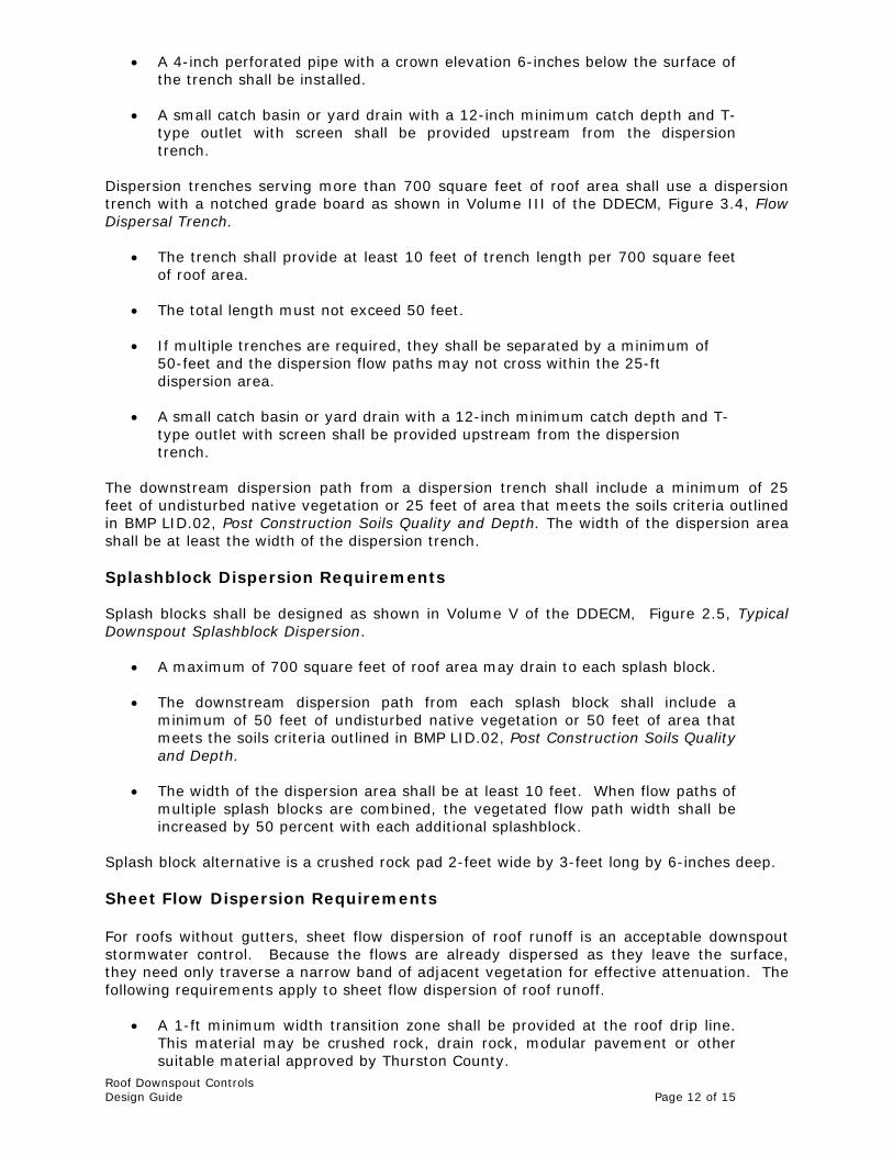
Dispersion trenches serving more than 700 square feet of roof area shall use a dispersion trench with a notched grade board as shown in Volume III of the DDECM, Figure 3.4, Flow Dispersal Trench.
The trench shall provide at least 10 feet of trench length per 700 square feet of roof area.
The total length must not exceed 50 feet.
If multiple trenches are required, they shall be separated by a minimum of
50-feet and the dispersion flow paths may not cross within the 25-ft dispersion area.
A small catch basin or yard drain with a 12-inch minimum catch depth and T-
type outlet with screen shall be provided upstream from the dispersion trench.
The downstream dispersion path from a dispersion trench shall include a minimum of 25 feet of undisturbed native vegetation or 25 feet of area that meets the soils criteria outlined in BMP LID.02, Post Construction Soils Quality and Depth. The width of the dispersion area shall be at least the width of the dispersion trench. Splashblock Dispersion Requirements Splash blocks shall be designed as shown in Volume V of the DDECM, Figure 2.5, Typical Downspout Splashblock Dispersion.
A maximum of 700 square feet of roof area may drain to each splash block. The downstream dispersion path from each splash block shall include a
minimum of 50 feet of undisturbed native vegetation or 50 feet of area that meets the soils criteria outlined in BMP LID.02, Post Construction Soils Quality and Depth.
The width of the dispersion area shall be at least 10 feet. When flow paths of
multiple splash blocks are combined, the vegetated flow path width shall be increased by 50 percent with each additional splashblock.
Splash block alternative is a crushed rock pad 2-feet wide by 3-feet long by 6-inches deep.
Sheet Flow Dispersion Requirements For roofs without gutters, sheet flow dispersion of roof runoff is an acceptable downspout stormwater control. Because the flows are already dispersed as they leave the surface, they need only traverse a narrow band of adjacent vegetation for effective attenuation. The following requirements apply to sheet flow dispersion of roof runoff.
A 1-ft minimum width transition zone shall be provided at the roof drip line. This material may be crushed rock, drain rock, modular pavement or other suitable material approved by Thurston County.

Roof Downspout Controls Design Guide Page 13 of 15
A vegetated flow path of 10 feet must be provided for up to 20 feet of roof
width contributing to the flow path. An additional 5 feet of flow path must be added for each additional 20 feet of roof width (or fraction thereof). For example, if the roof width from roof peak to eave is 50 feet, a minimum dispersion path length of 20 feet is required (10-ft for the 1st 20 feet, 5-ft for the next 20 feet, and 5-ft for the final 10-ft of roof width).
Sheet flow dispersion may not be appropriate where flow discharges toward
slopes steeper than 15 percent. A geotechnical report may be required to evaluate whether slopes exceeding 15 percent are suitable for sheet flow dispersion. The geotechnical analysis and report shall address the potential impact of dispersion on the slope.
C. Downspout Connection to Storm Drain System
If infiltration or dispersion is not feasible then downspouts shall be connected to the storm drainage system. Roof drain lines collecting individual downspouts from a building shall meet pipe size, slope and cleanout requirements of the applicable Building, Residential and Plumbing Codes, as required (The UPC requires cleanouts at the point of downspout leader connection to the collection line, every 100-feet and every cumulative 135 degree change in direction). For a residential subdivision, the downspouts shall be connected to the storm drainage system for the subdivision. Drainage outlets (stub-outs) are to be provided for each lot and shall conform to the following:
Each outlet shall be suitably located at the lowest elevation on the lot, so as to service all future roof downspouts and footing drains, driveways, yard drains, and any other surface or subsurface drains necessary to render the lots suitable for their intended use. Each outlet shall have free flowing, positive drainage to an acceptable storm water conveyance system or to an acceptable outfall location.
Outlets on each lot shall be located with a 5-foot-high, 2"x4" stake
marked "storm" or "drain." The stub-out shall visibly extend above surface level and be secured to the stake.
Pipe material shall be as acceptable to Thurston County. Rubber-gasketed
concrete or ADS N-12 is preferred. Other materials are acceptable with County acceptance including PVC, HDPE, corrugated aluminum, etc. (see Section 3.7.3 of Volume III for acceptable pipe materials).
Drainage easements are required for drainage systems designed to
convey flows through individual lots.
The developer and/or contractor is responsible for coordinating the locations of all stub-out conveyance lines with respect to the utilities (e.g., power, gas, telephone, television).
All individual stub-outs shall be privately owned and maintained by the lot
home owner.
Reference: Volume I of DDECM, Appendix I-G, Standard Stormwater Notes.

Roof Downspout Controls Design Guide Page 14 of 15
Access for Maintenance and Repair Provision shall be made for regular and perpetual maintenance and access to the infiltration drywell/trench or dispersion area. Adequate access, including measures to prevent encroachment into tracts/easements for purposes of inspection, operation and maintenance must be part of infiltration drywell/trench design. Provisions must be made for regular and perpetual maintenance of the infiltration drywell/trench or dispersion area, including replacement or reconstruction of any media used for treatment purposes. If subject to Minimum Requirement #10 (Operation and Maintenance), the Maintenance Plan shall be submitted to and approved by the County. For single family residential projects on a single lot no easements or tracts are required; however, the infiltration facilities and/or dispersion area shall be shown on the Abbreviated or Engineered Abbreviated Drainage plan recorded against the property at project’s end.
Submittal Information Include the following in any submittal documentation for the project:
Show on the work map included in the Drainage Report the following:
o Location of soil test pits/borings and associated soil logs. o Limits of contributing roof area for each dispersion or infiltration
BMP proposed for the project. o Location of infiltration drywells, trenches, or dispersion
trenches/splashblocks.
o Show location of clear dispersion flow path meeting minimum requirements.
Include in the construction plans and specifications:
o Location of roof downspouts, dispersion or infiltration facilities and dispersion areas.
o Roof area contributing to each dispersion/infiltration facility.
o Surface treatment for dispersion areas, whether native
vegetation or soils meeting requirements of BMP LID.02.
o Location of catch basins/yard drains with rim elevations and pipe invert elevations indicated.
o Pipe type, slope, size and invert elevations.
o Details, construction notes and specifications for all structures
and materials.
o If required to connect to the project or public stormwater system show roof drain lines and specify size, slope, materials, etc. and include locations and details of required cleanouts.

Roof Downspout Controls Design Guide Page 15 of 15
Include in the Drainage Report for the project:
o Documentation of soils evaluation establishing outwash soils for
prescriptive design methods. o Information on design infiltration rate calculation, if a non-
prescriptive infiltration method is proposed.
o Document infiltration/dispersion system meets any setback requirements.
o If the infiltration/dispersion facility is near or within the
minimum setback distance of 50-feet to a slope of greater than 15 percent and 10-ft height a geotechnical analysis and report shall be submitted.
o Hydrologic modeling results, if required, including a schematic
of the model setup referencing model basin identifiers to basins and sub-basins shown in the work map.
o Justify use of dispersion or direct connection to stormwater
system for roof downspouts instead of infiltration.
o Calculations for required infiltration trench length or drywell volume.
Abbreviated Drainage Plan Submittals For those projects allowed to submit an Abbreviated Drainage Plan or Engineered Abbreviated Drainage Plan and for which prescriptive infiltration methods or dispersion is used, the following shall be submitted with the Abbreviated Drainage Plan to meet the requirements of this BMP:
Identify on the Abbreviated Drainage Plan Plot Plan the areas dedicated to dispersion.
Show infiltration/dispersion trench or drywell locations and specify trench
lengths and drywell volume required.
Calculate and show roof area contributing to each dispersion or infiltration BMP.
Attach infiltration/dispersion trench details (at minimum make copies of
figures from Drainage manual and attach to plan).
If required to connect to the project or public stormwater system show roof drain lines and specify size, slope, materials, etc. and include locations and details of required cleanouts.

Downspout Controls Page 1 of 3 Review Checklist
ROOF DOWNSPOUT CONTROLS
Applicant Use REVIEW CHECKLIST Staff Use Only
APPLICABILITY & SPECIAL REQUIREMENTS
Is the project subject to Minimum Requirement #5, On-site Stormwater Management? If so, are downspout controls provided in accordance with BMP LID.04, BMP LID.05 or another suitable method based on circumstances.
If the project is not subject to Minimum Requirement #5, have downspout controls been implemented to the maximum extent practicable.
Are proposed downspout infiltration systems subject to registration as an Underground Injection Chamber (UIC)?
Verify that roof is composed on non-polluting surface. For a metal roof document that a non-pollutant generating coating is provided. For roofs on commercial or industrial buildings verify that requirements for Source Control (Section A7.9 of Volume IV) are complied with.
Is the project located in a Marine Bluff Hazard area? If so, downspout infiltration is not allowed without special acceptance by Thurston County.
DESIGN ELEMENTS
Is downspout infiltration feasible? Circumstances when it may not be feasible include: 1. Type C or D soils with <0.3”/hr infiltration rate 2. Depth from ground surface to groundwater or impermeable layer is less
than 3-ft, or less than 1-ft from bottom of drywell. 3. Infiltration facility cannot meet setback requirements 4. Steep slopes (>15%) and geotechnical engineer cannot demonstrate no
adverse impacts to the slope. 5. Fill soils that do not meet requirements for facilities on fill.
If infiltration is not feasible, is downspout dispersion feasible? Dispersion may not be feasible when: 1. May create flooding or erosion of downstream properties. 2. Insufficient dispersion area to meet minimum requirements. 3. Dispersion area is subject to saturated conditions or flooding. 4. Dispersion area cannot be permanently protected through covenant or
easement (for commercial projects). 5. Steep slopes (>15%) and geotechnical engineer cannot demonstrate no
adverse impacts to the slope. 6. Dispersion area cannot be located down slope of primary or reserve
drainfield area.
Downspout Infiltration Systems Prepare soils report. At a minimum at least one test pit shall be dug in the
vicinity of the infiltration system and a soils professional (including certified septic designer) shall document that soils in the vicinity of the infiltration trench are “outwash.” If contributing area is greater than 7,500 square feet or soils are not “outwash” then perform soils testing required by Volume III of DDECM to establish design infiltration rate.
Verify minimum depth to groundwater or impervious layer is met. For prescriptive trench design a minimum separation of 3-ft from ground surface is required. For prescriptive drywell design a minimum separation of 1-ft from the bottom of the drywell is required. For non-prescriptive design, a 3-ft separation from the base of the facility to seasonal high groundwater or impervious layer is required.
Is project subject to Minimum Requirement #7, Flow Control? If so, then prescriptive method for drywell design is not allowed.
Verify roof area contributing to each downspout infiltration system and submit calculations for length of trench or drywell volume based on roof contributing area for prescriptive designs.
Is a structure with a 12-inch minimum sump provided upstream of the infiltration trench or drywell? Is outlet designed to be submerged with a screen provided on the pipe outlet?
Is trench or drywell aggregate specified as 3/4 to 1-1 /2 inch washed round rock.

Downspout Controls Page 2 of 3 Review Checklist
If multiple infiltration trenches are provided, does trench separation meet minimum separation distance of 6-feet? If target infiltration zone is interflow, does trench separation meet minimum requirement of 25-feet.
For multiple drywells, is minimum drywell separation of 4-feet met? Do infiltration trenches follow a contour line? Does geotextile specification for drywell or infiltration meet requirements for
“Geotextile for Underground Drainage, low survivability, Class C as described in Volume V, Appendix V-B of DDECM?
For non-prescriptive design verify input data to WWHM3 model is consistent with plans and design infiltration rate calculation.
Check construction plans for layout of infiltration system. Verify that system meets setback requirements to slopes, building foundations, drainfield areas, etc.
Check construction plans for adequate details and specifications for proposed infiltration system.
For infiltration trenches in fill or under pavement, have special conditions been met?
Downspout Dispersion Systems Has applicant demonstrated that downspout infiltration is not feasible. Is there a risk of flooding or erosion to downstream properties? If so,
downspout dispersion is not allowed.
If dispersion system is within 50-feet of the top of a slope of 15 percent or greater with 10-ft height has a geotechnical analysis been completed documenting the potential impact of the facility on the slope.
Is the dispersion flow path downslope of the primary and reserve drainfield of an on-site septic system?
Is adequate dispersion path length provided prior to a property line, stream, wetland, or other impervious surface? (25-feet for dispersion trench, 50-feet for splashblock)
Verify roof area contributing to each downspout dispersion system and submit calculations for dispersion trench length or splash block area (700 sq ft max) based on roof contributing area.
Is a grade board type dispersion trench specified for contributing roof area greater than 700 square feet? (Figure 3.4 of Volume III of DDECM).
Do dispersion trenches meet maximum length requirement of 50-ft and minimum separation distance of 50-feet for multiple dispersion trenches?
For dispersion trenches is a structure with a 12-inch minimum sump provided upstream of the trench. Is outlet designed to be submerged with a screen provided on the pipe outlet?
Is dispersion trench design consistent with Figure 2.4 of Volume V of the DDECM or Figure 3.4 of Volume III of the DDECM if contributing roof area is greater than 700 square feet?
Is splash block dispersion design consistent with Figure 2.5 of Volume V of the DDECM?
Has dispersion area been increased 50% for splash block dispersion where dispersion areas cross?
For sheet flow dispersion (i.e. no roof gutters, water drips from roof line) is a 1-ft transition zone provided at the drip line?
For sheet flow dispersion has adequate dispersion length been provided? A vegetated flow path of 10-feet must be provided for up to 20 feet of roof width contributing to the flow path.
Downspout Connection to Storm Drainage System Applicant must demonstrate that downspout infiltration or dispersion is not
feasible prior to proposing connection to the storm drain system.
Does downspout collector system meet requirements for pipe size and cleanout locations per applicable building, residential, or plumbing codes?
For residential subdivisions are stub outlets provided for each lot and marked with a 5-ft high, 2”x4” stake marked “storm” or “drain.”
Is proposed pipe material acceptable to Thurston County. Rubber-gasketed concrete or ADS N-12 is preferred. Other materials are acceptable with County acceptance including PVC, HDPE, corrugated aluminum, etc. (see Section 3.7.3 of Volume III for acceptable pipe materials).
SUBMITTAL REQUIREMENTS Include geotechnical information including characterization of soils and show
location of test pit/borings excavated to establish soil conditions and/or design infiltration rate.
Show on site plans or Abbreviated Plan the location of downspouts and the contributing roof area to each downspout.

Downspout Controls Page 3 of 3 Review Checklist
Show on site plans or Abbreviated Plan the location of infiltration trenches, drywells, or dispersion trenches and proposed dispersion area.
Include in the drainage report calculations for required infiltration trench length and/or drywell volume for prescriptive designs.
Include modeling parameters and assumptions for non-prescriptive infiltration trench design using WWHM3.
Provide details and construction notes for trenches, drywells, catch basins, dispersion trenches, etc. to clearly show the construction of each system. For Abbreviated Drainage Plans, these can be copies of the standard details provided in the DDECM.
Provide justification for use of a downspout control system other than infiltration.
Identify dispersion area soil treatment, whether native vegetation or amended soils. If other than a residential project, provide information on how dispersion areas shall be protected by easement or covenant. For Abbreviated Plans, show the dispersion area on the recorded version of the Abbreviated Drainage Plan.

ATTACHMENTS
1. FIGURE 2.1: Typical Downspout Infiltration Trench 2. FIGURE 2.2: Alternative Downspout Infiltration Trench
System For Coarse Sand and Gravel 3. FIGURE 2.3: Typical Downspout Infiltration Drywell 4. FIGURE 2.4: Typical Downspout Dispersion Trench 5. FIGURE 2.5: Typical Downspout Splashblock Dispersion 6. Figure 3.4, Volume III: Flow Dispersal Trench

THURSTON COUNTY DRAINAGE DESIGN AND EROSION CONTROL MANUAL
Source: King County
Figure 2.1. Typical Downspout Infiltration Trench.
2-28 Volume V – Stormwater BMPs July 2009

THURSTON COUNTY DRAINAGE DESIGN AND EROSION CONTROL MANUAL
Source: King County
Figure 2.2. Alternative Downspout Infiltration Trench System for Coarse Sand and Gravel.
July 2009 Volume V – Stormwater BMPs 2-29

THURSTON COUNTY DRAINAGE DESIGN AND EROSION CONTROL MANUAL
Source: King County
Figure 2.3. Typical Downspout Infiltration Drywell.
July 2009 Volume V – Stormwater BMPs 2-31

THURSTON COUNTY DRAINAGE DESIGN AND EROSION CONTROL MANUAL
Source: King County
Figure 2.4. Typical Downspout Dispersion Trench.
July 2009 Volume V – Stormwater BMPs 2-35

THURSTON COUNTY DRAINAGE DESIGN AND EROSION CONTROL MANUAL
Roof downspout
serves up to 700 sf. Of roof
50’ min.Vegetatedflow path
Splashblock
Splashblock
Downspout extension
house
Figure 2.5. Typical Downspout Splashblock Dispersion.
Setbacks
Dispersion systems shall be set back at least 50 feet from top of slopes steeper than 15 percent and greater than 10 feet high. A geotechnical analysis and report must be prepared addressing the potential impact of the facility on the slope. The geotechnical report may recommend a reduced setback, but in no case shall the setback be less than the vertical height of the slope. The Administrator or designee may require a geotechnical report to evaluate whether a slope exceeding 15 percent is a landslide hazard area. Increased setbacks or prohibition of infiltration facilities may result from this report.
July 2009 Volume V – Stormwater BMPs 2-37

THURSTON COUNTY DRAINAGE DESIGN AND EROSION CONTROL MANUAL
Figure 3.4. Flow Dispersal Trench.
3-26 Volume III – Hydrologic Analysis and Flow Control BMPs July 2009