Embed Size (px)
Citation preview
DFIG Sliding Mode Control Driven byWind Turbine with Using a SVM Inverter for Improve the Quality of Energy Injected into the Electrical Grid63
DFIG Sliding Mode Control Driven byWind Turbine with Using a SVM Inverter forImprove the Quality of Energy Injected into
the Electrical Grid
Youcef Bekakra1 and Djilani Ben Attous2 , Non-members
ABSTRACT
This paper presents a simulation study of DoublyFed Induction Generator (DFIG) controlled by slid-ing mode control (SMC) applied to achieve controlof active and reactive powers exchanged between thestator of the DFIG and the grid. In this paper, avariable speed wind turbine is considered with DFIGand dierent power electronic converter topologies:(i) Carried based Pulse Width Modulation (PWM),(ii) Space Vector Modulation (SVM). To improve thequality of energy injected into the electrical grid, wepropose SVM technique which allows the minimizingof harmonics stator current and wide linear modu-lation range. The feasibility and eectiveness of themethod is demonstrated by simulation results. Theobtained results showed that, the proposed SMC withSVM inverter have stator and rotor current with lowharmonic distortion and low active and reactive pow-ers ripples than PWM inverter.
Keywords: Doubly fed induction generator, Windturbine, Sliding mode control, Space vector modula-tion, Pulse width modulation.
1. INTRODUCTION
Wind energy is becoming one of the most impor-tant renewable energy sources. Recently, power con-verter control has mostly been studied and developedfor wind energy conversion system (WECS) integra-tion in the electrical grid. The use of power electronicconverters allows variable speed operation of the windturbine where the WECS extracts maximum powerfrom the turbine [1].
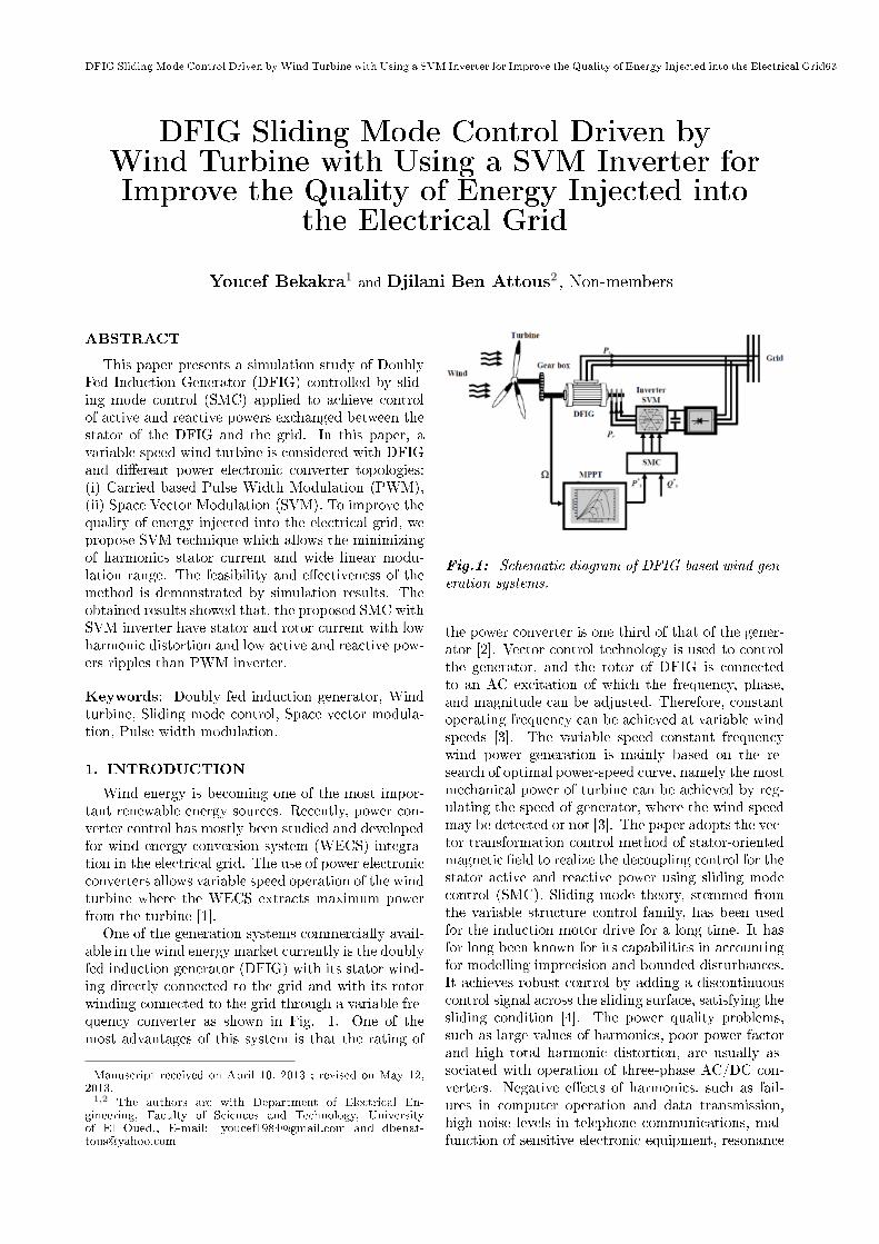
One of the generation systems commercially avail-able in the wind energy market currently is the doublyfed induction generator (DFIG) with its stator wind-ing directly connected to the grid and with its rotorwinding connected to the grid through a variable fre-quency converter as shown in Fig. 1. One of themost advantages of this system is that the rating of
Manuscript received on April 10, 2013 ; revised on May 12,2013.1,2 The authors are with Department of Electrical En-
gineering, Faculty of Sciences and Technology, Universityof El Oued., E-mail: [email protected] and [email protected]
Fig.1: Schematic diagram of DFIG-based wind gen-eration systems.
the power converter is one third of that of the gener-ator [2]. Vector control technology is used to controlthe generator, and the rotor of DFIG is connectedto an AC excitation of which the frequency, phase,and magnitude can be adjusted. Therefore, constantoperating frequency can be achieved at variable windspeeds [3]. The variable speed constant frequencywind power generation is mainly based on the re-search of optimal power-speed curve, namely the mostmechanical power of turbine can be achieved by reg-ulating the speed of generator, where the wind speedmay be detected or not [3]. The paper adopts the vec-tor transformation control method of stator-orientedmagnetic eld to realize the decoupling control for thestator active and reactive power using sliding modecontrol (SMC). Sliding mode theory, stemmed fromthe variable structure control family, has been usedfor the induction motor drive for a long time. It hasfor long been known for its capabilities in accountingfor modelling imprecision and bounded disturbances.It achieves robust control by adding a discontinuouscontrol signal across the sliding surface, satisfying thesliding condition [4]. The power quality problems,such as large values of harmonics, poor power factorand high total harmonic distortion, are usually as-sociated with operation of three-phase AC/DC con-verters. Negative eects of harmonics, such as fail-ures in computer operation and data transmission,high noise levels in telephone communications, mal-function of sensitive electronic equipment, resonance
64 ECTI TRANSACTIONS ON ELECTRICAL ENG., ELECTRONICS, AND COMMUNICATIONS VOL.11, NO.1 February 2013
conditions in power supply network, aging of insu-lation and additional losses in electrical machines,capacitive bank failures and so on, are well known.To diminish these eects, many countries have issuedharmonics limitation standards or recommendations[5]. Traditionally the sinusoidal pulse-width modu-lation (SPWM) technique is widely used in variablespeed drive of induction machine, especially for scalarcontrol where the stator voltage and frequency canbe controlled with minimum online computationalrequirement. In addition, this technique is easy toimplement. However, this algorithm has the follow-ing drawbacks. This technique is unable to fully uti-lize the available DC bus supply voltage to the volt-age source inverter. This technique gives more totalharmonic distortion (THD), this algorithm does notsmooth the progress of future development of vec-tor control implementation of AC drive. These draw-backs lead to development of a sophisticated PWMalgorithm which is Space Vector Modulation (SVM).This algorithm gives 15% more voltage output com-pare to the sinusoidal PWM algorithm, thereby in-creasing the DC bus utilization. Furthermore, it min-imizes the THD as well as loss due to minimize num-ber of commutations in the inverter [6]. In this pa-per, we apply the SMC method to the DFIG basedon wind energy using the modulation strategy knownas SVM technique and compared with the traditionalPWM technique.
2. MODELING OF THE WIND GENERA-TOR
The aerodynamic power, which is converted by awind turbine, Pt is dependent on the power coecientCp. It is given by [7]:
Pt =1
2CpρπR
2V 3 (1)
where ρ is the air density, R is the blade length andis the wind speed. The turbine torque is the ratio ofthe output power to the shaft speed Ωt:
Ct =Pt
Ωt(2)
The turbine is normally coupled to the generatorshaft through a gear box whose gear ratio is chosen inorder to set the generator shaft speed within a desiredspeed range. Neglecting the transmission losses, thetorque and shaft speed of the wind turbine, referredto the generator side of the gear box, are given by:
Cg =Ct
Gand Ωt =
Ωmec
G(3)
Where Ωmec is the generator shaft speed. A wind tur-bine can only convert just a certain percentage of thecaptured wind power. This percentage is representedby Cp(β, λ) which is function of the wind speed, the
turbine speed and the pith angle of specic wind tur-bine blades. Although this equation seems simple,Cp is dependent on the ratio λ between the turbineangular velocity Ωt and the wind speed v. This ratiois called the tip speed ratio:
λ =Ωt ·R
v(4)
Cp can be described as [8]:
Cp(β, λ) =(0.5− 0.0167(β − 2)) sinπ(λ+ 0.1)
18.5− 0.3(β − 2)
− 0.00184(λ− 3)(β − 2)
(5)
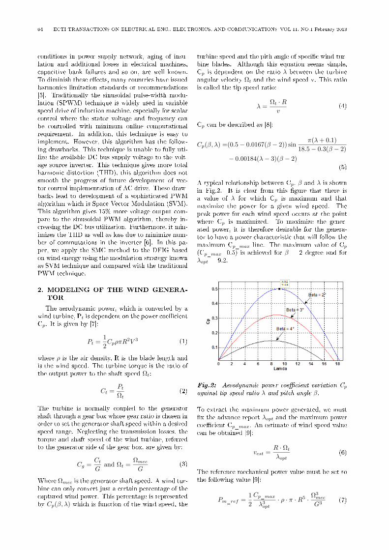
A typical relationship between Cp, β and λ is shownin Fig.2. It is clear from this gure that there isa value of λ for which Cp is maximum and thatmaximize the power for a given wind speed. Thepeak power for each wind speed occurs at the pointwhere Cp is maximized. To maximize the gener-ated power, it is therefore desirable for the genera-tor to have a power characteristic that will follow themaximum Cp_max line. The maximum value of Cp
(Cp_max=0.5) is achieved for β = 2 degree and forλopt = 9.2.
Fig.2: Aerodynamic power coecient variation Cp
against tip speed ratio λ and pitch angle β.
To extract the maximum power generated, we mustx the advance report λopt and the maximum powercoecient Cp_max. An estimate of wind speed valuecan be obtained [9]:
vest =R · Ωt
λopt(6)
The reference mechanical power value must be set tothe following value [9]:
Pm_ref =1
2
Cp_max
λ3opt
· ρ · π ·R5 · Ω3mec
G3(7)

DFIG Sliding Mode Control Driven byWind Turbine with Using a SVM Inverter for Improve the Quality of Energy Injected into the Electrical Grid65
Fig.3: Wind turbine model with torque control.
The electromagnetic torque reference value also mustbe set to the following value:
Cem_ref =Pm_ref
Ωt
=1
2
Cp_max
λ3opt
· ρ · π ·R5 · Ω3mec
G3
(8)
The simplied representation of wind turbine modelwith torque control in the form of diagram blocks isgiven in Fig.3. Fig. 4 shows the turbine mechanicalpowers various speed characteristics for dierent windspeeds, with indication of the maximum power pointtracking (MPPT) curve.
Fig.4: Turbine powers various speed characteristicsfor dierent wind speeds, with indication of the max-imum power point tracking (MPPT) curve.
3. DFIG MODELS
The general electrical state model of the inductionmachine obtained using Park transformation is given
by the following equations [10]: Stator and rotor volt-ages:
Vsd = Rs · isd + ddtϕsd − ωs · ϕsq
Vsq = Rs · isq + ddtϕsq + ωs · ϕsd
Vrd = Rr · ird + ddtϕrd − (ωs − ω) · ϕrq
Vrq = Rr · irq + ddtϕrq + (ωs − ω) · ϕrd
(9)
Stator and rotor uxes:ϕsd = Ls · isd +M · irdϕsq = Ls · isq +M · irqϕrd = Lr · ird +M · isdϕrq = Lr · irq +M · isq
(10)
The active and reactive powers at the stator and therotor as well as those provide for grid are dened as:
Psd = Vsd · isd + Vsq · isqQsd = Vsq · isd − Vsd · isq
(11)
Prd = Vrd · ird + Vrq · irqQrd = Vrq · ird − Vrd · irq
(12)
The electromagnetic torque is done as:
Ce = PM
Ls(ϕsdirq − ϕsqird) (13)
and its associated motion equation is:
Ce − Cr = Jdω
dt(14)
4. SPACE VECTOR MODULATION
The SVM method considers this interaction of thephase and optimizes the harmonic content of thethree phase isolated neutral load as shown in Fig. 5,[11]. The three phase sinusoidal and balance voltages

66 ECTI TRANSACTIONS ON ELECTRICAL ENG., ELECTRONICS, AND COMMUNICATIONS VOL.11, NO.1 February 2013
Fig.5: Voltage source inverter type 3 phase.
given by the equations as follows:VAn = Vm cosωt
VBn = Vm cos(ωt− 2π3 )
VCn = Vm cos(ωt+ 2π3 )
(15)
V − =2
3[VAn + aVBn + a2 · VCn] (16)
Are applied to the three phase DFIG, using (16). Athree phase bridge inverter, from Fig. 5, has 8 per-missible switching states. Table I gives summary ofthe switching states and the corresponding phase-to-neutral voltage of isolated neutral machine.
Vno =1
2median(VAn, VBn, VCn) (17)
Double edge modulation of reference voltageVAn,VBn,and VCn are equal as follows:
VAo = VAn + Vno
VBo = VBn + Vno
VCo = VCn + Vno
(18)
The underlying theory behind SVM is to apply space
Table 1: Summary of inverter switching states.
Name A B C VAn VBn VCn
V0 0 0 0 0 0 0V1 1 0 0 2VDC/3 -VDC/3 -VDC/3
V2 1 1 0 VDC/3 VDC/3 -2VDC/3
V3 0 1 0 -VDC/3 2VDC/3 -VDC/3
V4 0 1 1 -2VDC/3 VDC/3 VDC/3
V5 0 0 1 -VDC/3 -VDC/3 2VDC/3
V6 1 0 1 VDC/3 -2VDC/3 VDC/3
V7 1 1 1 0 0 0
vectors as illustrated in Fig. 6 for varying time peri-ods in a pattern based on the SVM algorithm.
4.1 The SVM generator
The SVM generator, whose operating principle ispresented in Fig. 7, contains seven blocks with thefollowing functions [12]:
Fig.6: Space vector of voltage.
• The three-phase generator is used to producethree sine waves with variable frequency and am-plitude; the three signals are out of phase witheach other by 120.
• The low-pass bus lter is used to remove fast tran-sients from the DC bus voltage measurement; thismeasure is used to compute the voltage vector ap-plied to the machine.
• The αβ transformation converts variables fromthe three-phase system to the two-phase αβ sys-tem.
• The αβ vector sector is used to nd the sector ofthe αβ plane in which the voltage vector lies; thisplane is divided into six dierent sectors spacedby 60.
• The ramp generator is used to produce a unitaryramp at the PWM switching frequency; this rampis used as a time base for the switching sequence.
• The switching time calculator is used to calculatethe timing of the voltage vector applied to themachine.
• The gates logic compares the ramp and the gatetiming signals to activate the inverter switches atthe proper time.
4.2 The simulation in Matlab/Simulink of theSVM generator
The Simulink scheme of SVM generator is pre-sented in Fig.8, the presentation in detail withthe simulation of the component blocks in Mat-lab/Simulink and the analyzing of the main signalsis done in [13].
5. ACTIVE AND REACTIVE DFIG INDI-RECT POWER CONTROL
A dâq reference frame synchronized with thestator ux is employed. By setting the quadratic com-ponent of the stator to the null value as follows [7]:
ϕsd = ϕs and ϕsq = 0 (19)

DFIG Sliding Mode Control Driven byWind Turbine with Using a SVM Inverter for Improve the Quality of Energy Injected into the Electrical Grid67
Fig.8: The Simulink scheme of SVM generator.
Fig.7: The operating principle of the inverter SVM.
Then the torque is simplied as indicated below:
Ce = PM
Lsirq · ϕsd (20)
The electromagnetic torque, and subsequently the ac-tive power; will only depend on the rotor currentalong the q-axis. By neglecting the stator resistanceRs, (9) gives:
Vsd = 0 and Vsq = Vs (21)
In order to calculate angles for the Park transforma-tion for stator and rotor variables, the stator pulsa-tion and the mechanical speed must be sensed.
By choosing this reference frame, stator voltagesand uxes can be rewritten as follows:
Vsd = 0 ;Vsq = Vs = ωS · ϕsd
ϕsd = ϕs = Ls · isd +M · ird ;
ϕrd = Lr · ird +M · isdϕsq = 0 = Ls · isq +M · irq ;
ϕrq = Lr · irq +M · isq
(22)
The stator active and reactive power can be writtenaccording to the rotor currents as:
Ps = −VsM
Lsirq (23)
Qs =V 2s
ωsLs− Vs
M
Lsird (24)
The arrangement of the equations gives the expres-sions of the rotor voltages according to the rotor cur-rents:
ird = − 1
σTrird + gωsirg +
1
σLrVrd (25)
irg =− 1
σ
( 1
Tr+
M2
LsTsLr
)irg − gωsird
+1
σLrVrq
(26)
with
σ = 1− M2
Ls · Lr;Tr =
Lr
Rr; g =
ωs − ω
ωs;Ts =
Ls
Rs
6. SLIDING MODE CONTROLLER
A Sliding Mode Controller (SMC) is a VariableStructure Controller (VSC). Basically, a VSC in-cludes several dierent continuous functions that canmap plant state to a control surface, whereas switch-ing among dierent functions is determined by plantstate represented by a switching function [14].
The design of the control system will be demon-strated for a following nonlinear system [15]:
x = f(x, y) +B(x, t) · u(x, t) (27)
Where x ∈ ℜn is the state vector, f(x, t) ∈ ℜn,B(x, t) ∈ ℜn×m, u ∈ ℜm is the control vector. Fromthe system (27), it possible to dene a set S of thestate trajectories such as:
S = x(t)|σs(x, t) = 0 (28)
68 ECTI TRANSACTIONS ON ELECTRICAL ENG., ELECTRONICS, AND COMMUNICATIONS VOL.11, NO.1 February 2013
Where
σs(x, t) = [σs1(x, t), σs2(x, t), ...., σ(x, t)]T (29)
and[.]T denotes the transposed vector, S is called
the sliding surface. To bring the state variable to thesliding surfaces, the following two conditions have tobe satised:
σs(x, t) = 0, σs(x, t) = 0 (30)
The control law satises the precedent conditions ispresented in the following form:
u = ueq + Un
un = −kfsgn(σs(x, t))(31)
Where u is the control vector, ueq is the equivalentcontrol vector, un is the switching part of the control(the correction factor), kf is the controller gain. ueq
can be obtained by considering the condition for thesliding regimen, σs(x, t) = 0 . The equivalent controlkeeps the state variable on sliding surface, once theyreach it. For a dened function φ [16], [17], as shownin Fig.9:
sgn(φ) =
1, if φ > 0
0, if φ = 0
−1, if φ < 0
(32)
The controller described by the equation (31)
Fig.9: Sgn function.
presents high robustness, insensitive to parameteructuations and disturbances, but it will have high-frequency switching (chattering phenomena) near thesliding surface due to function involved. These dras-tic changes of input can be avoided by introducinga boundary layer with width ϵ [15]. Thus replacingsgn(σs(x, t)) by sat(σs(x, t)) (saturation function), in(31), we have:
u = ueq − kfsat(σs(x, t)) (33)
Where ϵ > 0:
sat(φ) =
sgn(φ), if |φ| > ϵ
φ, if φ < ϵ(34)
Fig.10 shows the saturation function. Consider a Lya-
Fig.10: Saturation function.
punov function [16]:
V =1
2σ2s (35)
From Lyapunov theorem we know that if V is nega-tive denite, the system trajectory will be driven andattracted toward the sliding surface and remain slid-ing on it until the origin is reached asymptotically[15]:
V =1
2
d
dtσ2s = σsσs 6 −η|σs| (36)
Where η is a strictly positive constant.In this paper, we use the sliding surface proposed
par J.J. Slotine,
σs(x, t) =
(d
dt+ τ
)n−1
e (37)
Where: x = [x, x, ..., xn−1]T is the state vector, xd =
[xd, xd, ..., xn−1d ]
Tis the desired state vector, e = xd−
x = [e, e, ..., en−1]T is the error vector, and τ is a
positive coecient, and n is the system order.Commonly, in doubly fed induction machine
(DFIM) control using sliding mode theory, the sur-faces are chosen as functions of the error between thereference input signal and the measured signals [15].
7. APPLICATION OF SLIDING MODECONTROL TO DFIG
The rotor currents irq and ird are the images re-spectively of stator active power Ps and stator reac-tive power Qs have to track appropriate current ref-erences, so, a sliding mode control based on the abovePark reference frame is used.
7.1 Quadratic rotor current control with SMC
The sliding surface representing the error betweenthe measured and reference quadratic rotor current isgiven by this relation:
e = irq∗ − irq (38)
For n = 1 , the speed control manifold equation canbe obtained from equation (37) as follow:
σs(irq) = e = irq∗ − irq (39)

DFIG Sliding Mode Control Driven byWind Turbine with Using a SVM Inverter for Improve the Quality of Energy Injected into the Electrical Grid69
σs(irq) = ˙irq∗ − ˙irq (40)
Substituting the expression of ˙irq equation (26) inequation (40), we obtain:
σ(irq) = ˙irq∗−
(− 1
σ
(1
Tr+
M2
LSTsLr
)irq
− gωsird +1
σLrVrq
(41)
We take:
Vrq = V eqrq + V n
rq (42)
During the sliding mode and in permanent regime,we have:
σs(irq) = 0, σs(irq) = 0, V nrq = 0 (43)
Where the equivalent control is:
V eqrq =
(˙irq∗ +
1
σ
(1
Tr+
M2
LSTsLr
)irq + gωsird
)σLr
(44)
Therefore, the correction factor is given by:
V nrq = kVrqsat(σs(irq)) (45)
kvrq : positive constant.
7.2 Direct rotor current control with SMC
The sliding surface representing the error betweenthe measured and reference direct rotor current isgiven by this relation:
e = ird∗ − ird
∗ − ird (46)
For n = 1, the speed control manifold equation canbe obtained from equation (37) as follow:
σs(ird) = e = ird∗ − ird (47)
σs(ird) = ˙ird∗ − ˙ird (48)
Substituting the expression of ˙ird equation (25) inequation (48), we obtain:
σs(ird) = ˙ird∗−
(− 1
σTrird + gωsirq +
1
σLrVrd
)(49)
We take:
Vrd = V eqrd + V n
rd (50)
During the sliding mode and in permanent regime,we have:
σs(ird) = 0, σs(ird) = 0, V nrd = 0 (51)
Where the equivalent control is:
V eqrd =
(˙ird∗ +
1
σTrird − gωsirq
)σLr (52)
Therefore, the correction factor is given by:
V nrd = kVrd
sat(σs(ird)) (53)
kVrd: positive constant.
8. SIMULATION RESULTS
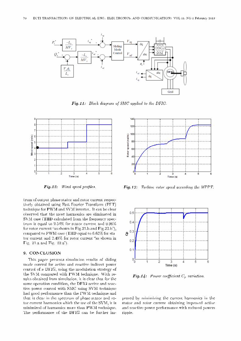
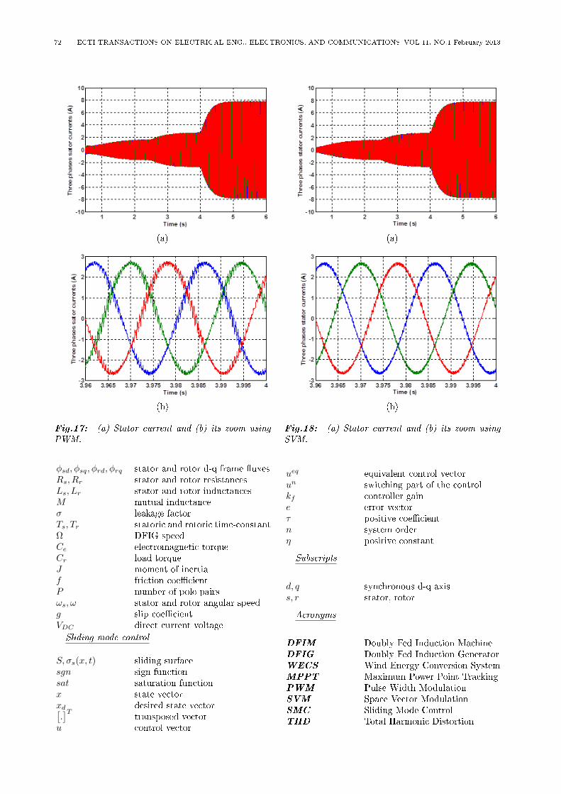
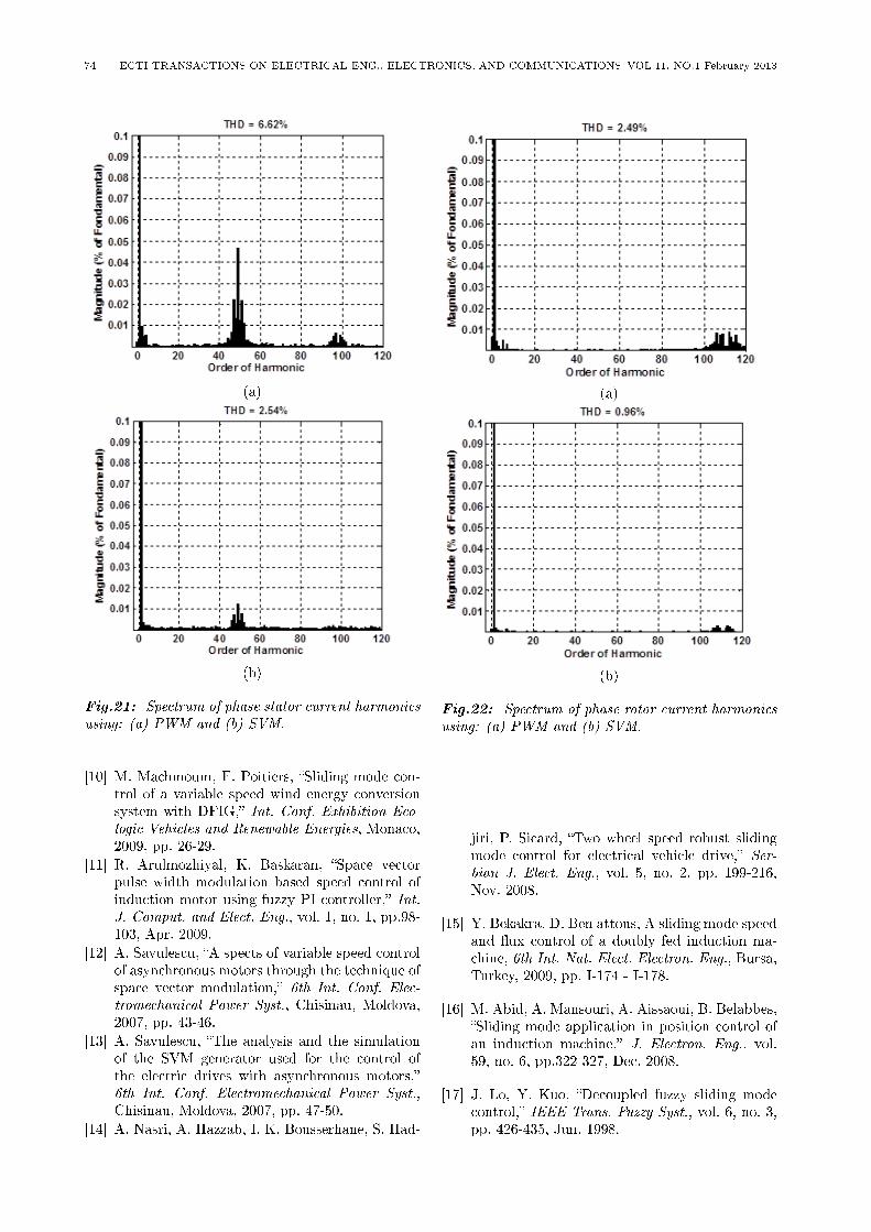
The complete control block diagram employing thesliding mode controller for stator active and reactivepowers control is shown in Fig. 11. It shows theoverall d-q vector control structure using the statorux oriented frame using the sliding mode controller,the blocks represent the proposed sliding mode con-trollers of direct and quadratic rotor current. Theblock `dq/abc' makes the conversion between the syn-chronously rotating and stationary reference frame.The block `abc /dq' makes the inversion `dq/abc'block. The block `SVM' shows the control by tech-nique space vector modulation whose is realized forthe inverter control, which feeds the rotor through aconverter. The block `DFIG' represents the doublyfed induction generator coupled with wind turbine.The DFIG used in this work is a 4 kW, whose nominalparameters are indicated in appendix A. To verify thefeasibility of the proposed control scheme, computersimulations were performed using Matlab/Simulinksoftware. The block diagram was realized and ex-ecuted on Intel Celeron PC having 2.5 GHz CPU,1GB DDR RAM. In this section, simulation resultsare given to illustrate the system performance of theproposed SMC with SVM inverter schemes and com-pared with SMC with PWM inverter. The variationof wind speed is simulated in Fig. 12, the wind speedis start at 4m/s, at 2.5s, it suddenly changing at 5m/s,as 4s, it is 8 m/s. Fig. 13 shows the turbine rotorspeed according the MPPT. After each variation ofwind speed, the turbine rotor speed stables totallywith the theoretical value. During this variation pro-cess, realize the maximum wind energy tracking con-trol. Fig.14 shows the power coecient variation Cp,it is kept around its maximum value Cp = 5. The Fig.15 presents the stator active power and theirs refer-ence proles injected into the grid using two level in-verter controlled by PWM and SVM technique. Thestator reactive power and theirs reference proles us-ing PWM and SVM are presented in Fig.16. After theFig.15 and Fig.16 a very good decoupling between thestator active and reactive powers is obtained in thetwo cases where used PWM and SVM technique. Itis clear that the actual stator active power follows itsdesired values using the proposed controller incorpo-rating PWM and SVM technique, and to guaranteea unity power factor at the stator side, the reactivepower is maintained to zero. Ripples on active andreactive powers are reduced in SVM case where com-pared SVM with PWM as shown clearly in Fig.15and Fig.16. Fig.17 and Fig 18 show stator currentversus time using PWM and SVM respectively withtheirs zoom. Fig.19 and Fig.20 present the rotor cur-rent of the DFIG using PWM and SVM respectivelyand theirs zoom. After Fig.17, Fig.18, Fig.19 andFig.20, we observe that with when the wind speedincreasing the amplitude of stator and rotor currentincreases. Fig.21 and Fig.22 show the harmonic spec-
70 ECTI TRANSACTIONS ON ELECTRICAL ENG., ELECTRONICS, AND COMMUNICATIONS VOL.11, NO.1 February 2013
Fig.11: Block diagram of SMC applied to the DFIG.
Fig.12: Wind speed proles.
trum of output phase stator and rotor current respec-tively obtained using Fast Fourier Transform (FFT)technique for PWM and SVM inverter. It can be clearobserved that the most harmonics are eliminated inSVM case (THD calculated from the frequency spec-trum is equal to 2.54% for stator current and 0.96%for rotor current as shown in Fig.21.b and Fig.22.b),compared to PWM case (THD equal to 6.62% for sta-tor current and 2.49% for rotor current as shown inFig. 21.a and Fig. 22.a).
9. CONCLUSION
This paper presents simulation results of slidingmode control for active and reactive indirect powercontrol of a DFIG, using the modulation strategy ofthe SVM compared with PWM technique. With re-sults obtained from simulation, it is clear that for thesame operation condition, the DFIG active and reac-tive power control with SMC using SVM techniquehad good performance than the PWM technique andthat is clear in the spectrum of phase stator and ro-tor current harmonics which the use of the SVM, it isminimized of harmonics more than PWM technique.The performance of the DFIG can be further im-
Fig.13: Turbine rotor speed according the MPPT.
Fig.14: Power coecient Cp variation.
proved by minimizing the current harmonics in thestator and rotor current obtaining improved activeand reactive power performance with reduced powersripple.

DFIG Sliding Mode Control Driven byWind Turbine with Using a SVM Inverter for Improve the Quality of Energy Injected into the Electrical Grid71
(a)
(b)
Fig.15: Stator active power injected into the gridusing: (a) PWM and (b) SVM.
APPENDIX
Appendix I. System parameters.
DFIG data:
Rated values:4 kW, 220/380 V, 50Hz, 15/8.6 ARated parameters:RS = 1.2ΩRr = 1.8ΩLS = 0.1554HM = 0.15HP = 2Mechanical constants:J = 0.2Kg.m2
f = 0.001N.m.s/rad
Wind turbine data:
R = 3m,G = 5.4, Numberofbleades = 3
Air density value:
ρ = 1.22Kg/m3
(a)
(b)
Fig.16: Stator reactive power using: (a) PWM and(b) SVM.
Appendix II. Nomenclature.
Turbine
Ωmec mechanical speed of the DFIGΩt turbine speedPt turbine aerodynamic powerPm_ref reference mechanical powerCp power coecientCp_max maximum power coecientCt turbine torqueCem_ref reference electromagnetic torquev wind speedvest estimated wind speedλ tip speed ratioλopt optimum tip speed ratioβ pitch angleR blade lengthG gear boxDFIG
Ps, Qs active and reactive stator powerPr, Qr active and reactive rotor powerVsd, Vsq, Vrd, Vrq stator and rotor d-q frame volt-
ages
72 ECTI TRANSACTIONS ON ELECTRICAL ENG., ELECTRONICS, AND COMMUNICATIONS VOL.11, NO.1 February 2013
(a)
(b)
Fig.17: (a) Stator current and (b) its zoom usingPWM.
ϕsd, ϕsq, ϕrd, ϕrq stator and rotor d-q frame uxesRs, Rr stator and rotor resistancesLs, Lr stator and rotor inductancesM mutual inductanceσ leakage factorTs, Tr statoric and rotoric time-constantΩ DFIG speedCe electromagnetic torqueCr load torqueJ moment of inertiaf friction coecientP number of pole pairsωs, ω stator and rotor angular speedg slip coecientVDC direct current voltageSliding mode control
S, σs(x, t) sliding surfacesgn sign functionsat saturation functionx state vectorxd desired state vector[.]T
transposed vectoru control vector
(a)
(b)
Fig.18: (a) Stator current and (b) its zoom usingSVM.
ueq equivalent control vectorun switching part of the controlkf controller gaine error vectorτ positive coecientn system orderη positive constant
Subscripts
d, q synchronous d-q axiss, r stator, rotor
Acronyms
DFIM Doubly Fed Induction MachineDFIG Doubly Fed Induction GeneratorWECS Wind Energy Conversion SystemMPPT Maximum Power Point TrackingPWM Pulse Width ModulationSVM Space Vector ModulationSMC Sliding Mode ControlTHD Total Harmonic Distortion

DFIG Sliding Mode Control Driven byWind Turbine with Using a SVM Inverter for Improve the Quality of Energy Injected into the Electrical Grid73
(a)
(b)
Fig.19: (a) Rotor current and (b) its zoom usingPWM.
References
[1] A. Gaillard, P. Poure, S. Saadate, M. Mach-moum, Variable speed DFIG wind energy sys-tem for power generation and harmonic currentmitigation, Renewable Energy, vol. 34, iss. 6,pp. 1545-1553, Jun. 2009.
[2] M. Verij Kazemi, A. Sadeghi Yazdankhah, H.Madadi Kojabadi, Direct power control ofDFIG based on discrete space vector modula-tion,Renewable Energy, vol. 35, iss. 5, pp. 1033-1042, May 2010.
[3] WU Guo-qing, NI Hong-jun, WU Guo-xiang,ZHOU Jing-ling, Zhu Wei-nan, MAO Jing-feng,CAO Yang, On maximum power point track-ing control strategy for variable speed constantfrequency wind power generation, J. ChongqingUniversity, vol. 9, no. 1, pp. 21-28, Mar. 2010.
[4] A. Hazzab, I. K. Bousserhane, M. Kamli, M.Rahli, Adaptive fuzzy PI-sliding mode con-troller for induction motor speed control, Int.J. Emerging Electric Power Syst., vol. 4, no. 1,pp. 1-13, Nov. 2005.
(a)
(b)
Fig.20: (a) Rotor current and (b) its zoom usingSVM.
[5] V. Katic, D. Graovac, A method of real anal-ysis of AC/DC converter line side harmonics,Electronics and Energetics, vol. 10, no. 1, pp.107-123, month 1997.
[6] A. Jidin, T. Sutikno, Matlab/simulink basedanalysis of voltage source inverter with spacevector modulation, TELKOMNIKA, vol. 7, no.1, pp. 23-30, Apr. 2009.
[7] D. Aouzellag, K. Ghedamsi, E.M. Berkouk, Net-work power ux control of a wind generator,Renewable Energy, vol. 34, iss. 3, pp. 615-622,Mar. 2009.
[8] E. S. Abdin, W. Xu, Control design and dy-namic performance analysis of wind turbine-induction generator unit, IEEE Trans. EnergyConvers., vol. 15, no. 1, pp.91-96, Mar. 2000.
[9] Youcef Bekakra and Djilani Ben attous, Ac-tive and reactive power control of a DFIG withMPPT for Variable Speed wind energy conver-sion using sliding mode control, World AcademySci., Eng. Technology, vol. 60, pp. 1543-1549,Dec. 2011.
74 ECTI TRANSACTIONS ON ELECTRICAL ENG., ELECTRONICS, AND COMMUNICATIONS VOL.11, NO.1 February 2013
(a)
(b)
Fig.21: Spectrum of phase stator current harmonicsusing: (a) PWM and (b) SVM.
[10] M. Machmoum, F. Poitiers, Sliding mode con-trol of a variable speed wind energy conversionsystem with DFIG, Int. Conf. Exhibition Eco-logic Vehicles and Renewable Energies, Monaco,2009, pp. 26-29.
[11] R. Arulmozhiyal, K. Baskaran, Space vectorpulse width modulation based speed control ofinduction motor using fuzzy PI controller, Int.J. Comput. and Elect. Eng., vol. 1, no. 1, pp.98-103, Apr. 2009.
[12] A. Savulescu, A spects of variable speed controlof asynchronous motors through the technique ofspace vector modulation, 6th Int. Conf. Elec-tromechanical Power Syst., Chisinau, Moldova,2007, pp. 43-46.
[13] A. Savulescu, The analysis and the simulationof the SVM generator used for the control ofthe electric drives with asynchronous motors,6th Int. Conf. Electromechanical Power Syst.,Chisinau, Moldova, 2007, pp. 47-50.
[14] A. Nasri, A. Hazzab, I. K. Bousserhane, S. Had-
(a)
(b)
Fig.22: Spectrum of phase rotor current harmonicsusing: (a) PWM and (b) SVM.
jiri, P. Sicard, Two wheel speed robust slidingmode control for electrical vehicle drive, Ser-bian J. Elect. Eng., vol. 5, no. 2, pp. 199-216,Nov. 2008.
[15] Y. Bekakra, D. Ben attous, A sliding mode speedand ux control of a doubly fed induction ma-chine, 6th Int. Nat. Elect. Electron. Eng., Bursa,Turkey, 2009, pp. I-174 - I-178.
[16] M. Abid, A. Mansouri, A. Aissaoui, B. Belabbes,Sliding mode application in position control ofan induction machine, J. Electron. Eng., vol.59, no. 6, pp.322-327, Dec. 2008.
[17] J. Lo, Y. Kuo, Decoupled fuzzy sliding modecontrol, IEEE Trans. Fuzzy Syst., vol. 6, no. 3,pp. 426-435, Jun. 1998.

DFIG Sliding Mode Control Driven byWind Turbine with Using a SVM Inverter for Improve the Quality of Energy Injected into the Electrical Grid75
Youcef BEKAKRA was born in El-Oued, Algeria in 1984. He receivedthe B.Sc degree in Electrical Engineer-ing from El-Oued University, Algeria in2007, his MSc degree from El-Oued Uni-versity in 2010. He is currently work-ing towards his PhD degree in Electri-cal Engineering from Biskra University,Algeria. His areas of interest are renew-able energy, Electrical Drives and Pro-cess Control, application of Articial In-
telligence techniques for control and optimize electric powersystems.
Djilani BEN ATTOUS was born inEl-Oued, Algeria in 1959. He receivedhis Engineer degree in Electrotechnicsfrom Polytechnic National Institute Al-giers, Algeria in 1984. He got MScdegree in Power Systems from UMISTEngland in 1987. In 2000, he receivedhis doctorate of state (PhD degree) fromBatna University, Algeria. He is cur-rently associate professor at El-OuedUniversity, Algeria in Electrical Engi-
neering. His research interests in Planning and Economic ofElectric Energy System, Optimization Theory and its applica-tions and he also investigated questions related with ElectricalDrives and Process Control. He is member of the VTRS re-search Laboratory.