Embed Size (px)
Citation preview
Nor
th A
mer
ica
Onl
y
DFA Series
D10
3809
X01
2
Instruction Manual
January 2016
www.enardo.com
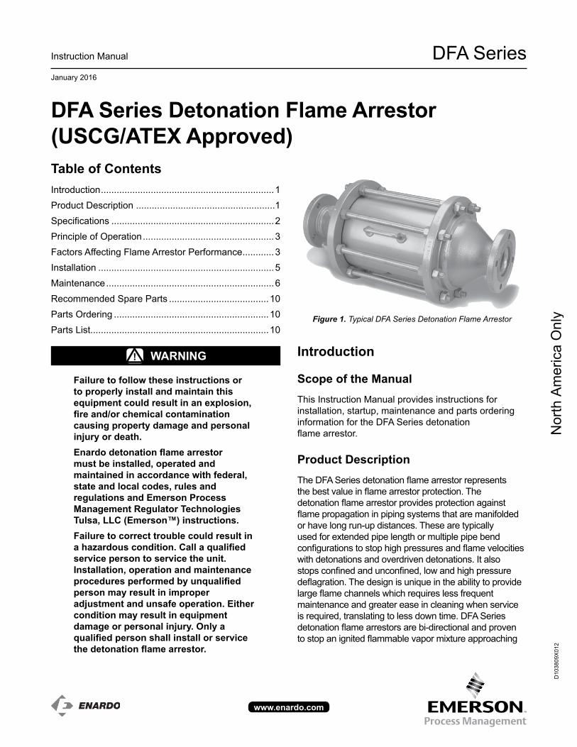
Figure 1. Typical DFA Series Detonation Flame Arrestor
DFA Series Detonation Flame Arrestor (USCG/ATEX Approved)
WArninG!
Failure to follow these instructions or to properly install and maintain this equipment could result in an explosion, fire and/or chemical contamination causing property damage and personal injury or death.Enardo detonation flame arrestor must be installed, operated and maintained in accordance with federal, state and local codes, rules and regulations and Emerson Process Management regulator Technologies Tulsa, LLC (Emerson™) instructions. Failure to correct trouble could result in a hazardous condition. Call a qualified service person to service the unit. installation, operation and maintenance procedures performed by unqualified person may result in improper adjustment and unsafe operation. Either condition may result in equipment damage or personal injury. Only a qualified person shall install or service the detonation flame arrestor.
introduction
Scope of the ManualThis Instruction Manual provides instructions for installation, startup, maintenance and parts ordering information for the DFA Series detonation flame arrestor.
Product DescriptionThe DFA Series detonation flame arrestor represents the best value in flame arrestor protection. The detonation flame arrestor provides protection against flame propagation in piping systems that are manifolded or have long run-up distances. These are typically used for extended pipe length or multiple pipe bend configurations to stop high pressures and flame velocities with detonations and overdriven detonations. It also stops confined and unconfined, low and high pressure deflagration. The design is unique in the ability to provide large flame channels which requires less frequent maintenance and greater ease in cleaning when service is required, translating to less down time. DFA Series detonation flame arrestors are bi-directional and proven to stop an ignited flammable vapor mixture approaching
Table of ContentsIntroduction ..................................................................1Product Description .....................................................1Specifications ..............................................................2Principle of Operation ..................................................3Factors Affecting Flame Arrestor Performance ............3Installation ...................................................................5Maintenance ................................................................6Recommended Spare Parts ......................................10Parts Ordering ...........................................................10Parts List....................................................................10
Nor
th A
mer
ica
Onl
y
DFA Series
2
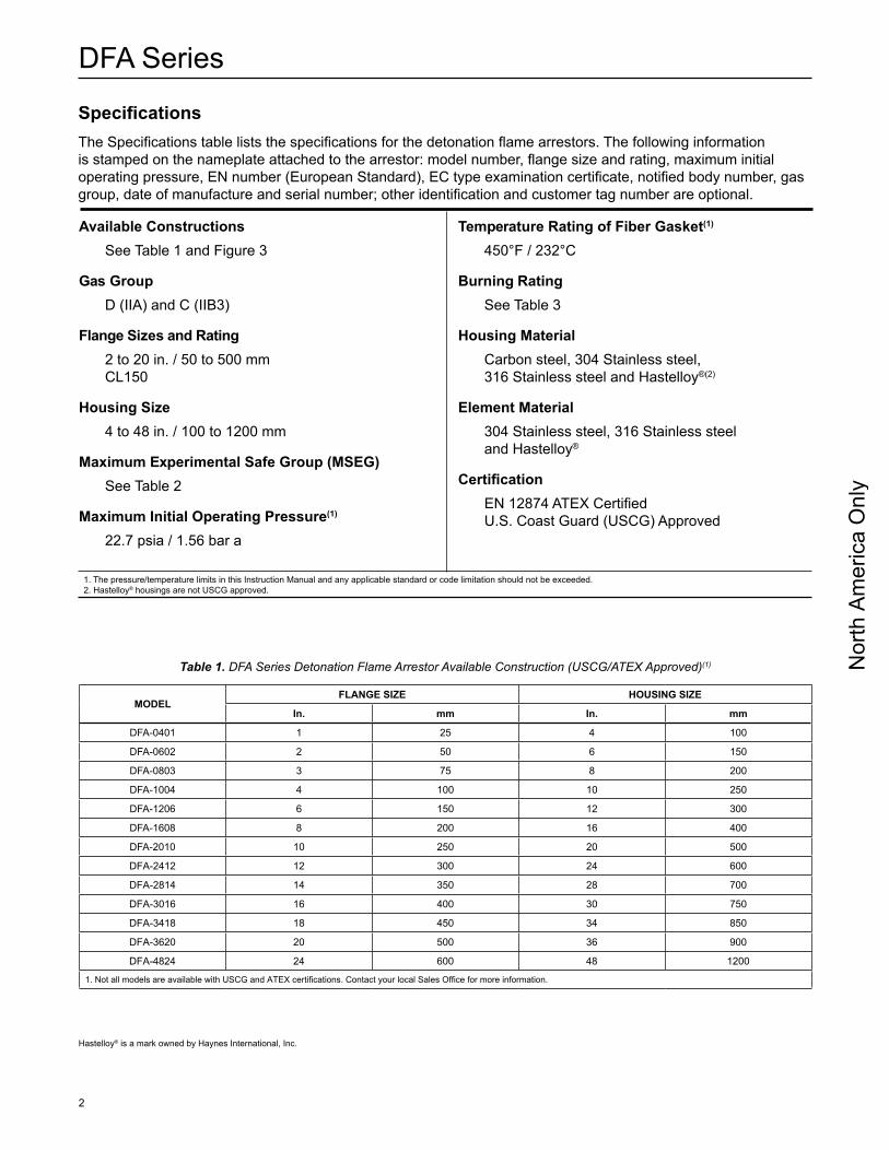
SpecificationsThe Specifications table lists the specifications for the detonation flame arrestors. The following information is stamped on the nameplate attached to the arrestor: model number, flange size and rating, maximum initial operating pressure, EN number (European Standard), EC type examination certificate, notified body number, gas group, date of manufacture and serial number; other identification and customer tag number are optional.
Available ConstructionsSee Table 1 and Figure 3
Gas GroupD (IIA) and C (IIB3)
Flange Sizes and rating2 to 20 in. / 50 to 500 mm CL150
Housing Size4 to 48 in. / 100 to 1200 mm
Maximum Experimental Safe Group (MSEG)See Table 2
Maximum initial Operating Pressure(1)
22.7 psia / 1.56 bar a
Temperature rating of Fiber Gasket(1)
450°F / 232°C
Burning rating See Table 3
Housing MaterialCarbon steel, 304 Stainless steel, 316 Stainless steel and Hastelloy®(2)
Element Material304 Stainless steel, 316 Stainless steel and Hastelloy®
CertificationEN 12874 ATEX CertifiedU.S. Coast Guard (USCG) Approved
1. The pressure/temperature limits in this Instruction Manual and any applicable standard or code limitation should not be exceeded.2. Hastelloy® housings are not USCG approved.
Table 1. DFA Series Detonation Flame Arrestor Available Construction (USCG/ATEX Approved)(1)
MODELFLAnGE SiZE HOUSinG SiZE
in. mm in. mm
DFA-0401 1 25 4 100
DFA-0602 2 50 6 150
DFA-0803 3 75 8 200
DFA-1004 4 100 10 250
DFA-1206 6 150 12 300
DFA-1608 8 200 16 400
DFA-2010 10 250 20 500
DFA-2412 12 300 24 600
DFA-2814 14 350 28 700
DFA-3016 16 400 30 750
DFA-3418 18 450 34 850
DFA-3620 20 500 36 900
DFA-4824 24 600 48 1200
1. Not all models are available with USCG and ATEX certifications. Contact your local Sales Office for more information.
Hastelloy® is a mark owned by Haynes International, Inc.
Nor
th A
mer
ica
Onl
y
DFA Series
3
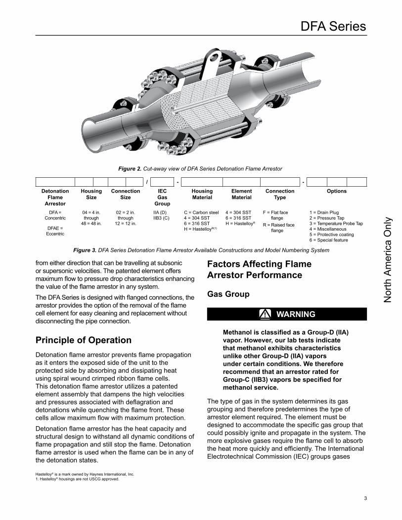
/ - -Detonation
Flame Arrestor
Housing Size
Connection Size
iEC Gas
Group
Housing Material
Element Material
Connection Type
Options
DFA = Concentric
DFAE = Eccentric
04 = 4 in. through
48 = 48 in.
02 = 2 in. through
12 = 12 in.
IIA (D) IIB3 (C)
C = Carbon steel 4 = 304 SST 6 = 316 SST H = Hastelloy®(1)
4 = 304 SST 6 = 316 SST H = Hastelloy®
F = Flat face flange
R = Raised face flange
1 = Drain Plug2 = Pressure Tap 3 = Temperature Probe Tap4 = Miscellaneous5 = Protective coating6 = Special feature
Factors Affecting Flame Arrestor Performance
Gas Group
WArninG!
Methanol is classified as a Group-D (IIA) vapor. However, our lab tests indicate that methanol exhibits characteristics unlike other Group-D (iiA) vapors under certain conditions. We therefore recommend that an arrestor rated for Group-C (IIB3) vapors be specified for methanol service.
The type of gas in the system determines its gas grouping and therefore predetermines the type of arrestor element required. The element must be designed to accommodate the specific gas group that could possibly ignite and propagate in the system. The more explosive gases require the flame cell to absorb the heat more quickly and efficiently. The International Electrotechnical Commission (IEC) groups gases
from either direction that can be travelling at subsonic or supersonic velocities. The patented element offers maximum flow to pressure drop characteristics enhancing the value of the flame arrestor in any system. The DFA Series is designed with flanged connections, the arrestor provides the option of the removal of the flame cell element for easy cleaning and replacement without disconnecting the pipe connection.
Principle of OperationDetonation flame arrestor prevents flame propagation as it enters the exposed side of the unit to the protected side by absorbing and dissipating heat using spiral wound crimped ribbon flame cells. This detonation flame arrestor utilizes a patented element assembly that dampens the high velocities and pressures associated with deflagration and detonations while quenching the flame front. These cells allow maximum flow with maximum protection.Detonation flame arrestor has the heat capacity and structural design to withstand all dynamic conditions of flame propagation and still stop the flame. Detonation flame arrestor is used when the flame can be in any of the detonation states.
Figure 2. Cut-away view of DFA Series Detonation Flame Arrestor
Figure 3. DFA Series Detonation Flame Arrestor Available Constructions and Model Numbering System
Hastelloy® is a mark owned by Haynes International, Inc.1. Hastelloy® housings are not USCG approved.
Nor
th A
mer
ica
Onl
y
DFA Series
4
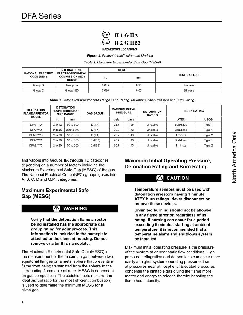
Table 2. Maximum Experimental Safe Gap (MESG)
nATiOnAL ELECTriC CODE (nEC)
inTErnATiOnAL ELECTrOTECHniCAL
COMMiSSiOn (iEC) GrOUP
MESG
TEST GAS LiSTin. mm
Group D Group IIA 0.035 0.90 Propane
Group C Group IIB3 0.026 0.65 Ethylene
HAZArDOUS LOCATiOnS
Figure 4. Product Identification and Marking
and vapors into Groups IIA through IIC categories depending on a number of factors including the Maximum Experimental Safe Gap (MESG) of the gas. The National Electrical Code (NEC) groups gases into A, B, C, D and G.M. categories.
Maximum Experimental Safe Gap (MESG)
WArninG!
Verify that the detonation flame arrestor being installed has the appropriate gas group rating for your process. This information is included in the nameplate attached to the element housing. Do not remove or alter this nameplate.
The Maximum Experimental Safe Gap (MESG) is the measurement of the maximum gap between two equatorial flanges on a metal sphere that prevents a flame from being transmitted from the sphere to the surrounding flammable mixture. MESG is dependent on gas composition. The stoichiometric mixture (the ideal air/fuel ratio for the most efficient combustion) is used to determine the minimum MESG for a given gas.
Maximum initial Operating Pressure, Detonation rating and Burn rating
CAUTiOn
Temperature sensors must be used with detonation arrestors having 1 minute ATEX burn ratings. never disconnect or remove these devices.Unlimited burning should not be allowed in any flame arrestor, regardless of its rating. if burning can occur for a period exceeding 5 minutes starting at ambient temperature, it is recommended that a temperature alarm and shutdown system be installed.
Maximum initial operating pressure is the pressure of the system at or near static flow conditions. High pressure deflagration and detonations can occur more easily at higher system operating pressures than at pressures near atmospheric. Elevated pressures condense the ignitable gas giving the flame more matter and energy to release thereby boosting the flame heat intensity.
DETOnATiOn FLAME ArrESTOr
MODEL
DETOnATiOn FLAME ArrESTOr
SiZE rAnGE GAS GrOUPMAXiMUM iniTiAL
PrESSUrE DETOnATiOn rATinG
BUrn rATinG
in. mm psia bar a ATEX USCG
DFA***/D 2 to 12 50 to 300 D (IIA) 22.7 1.56 Unstable Stabilized Type 1
DFA***/D 14 to 20 350 to 500 D (IIA) 20.7 1.43 Unstable Stabilized Type 1
DFAE***/D 2 to 20 50 to 500 D (IIA) 20.7 1.43 Unstable 1 minute Type 2
DFA***/C 2 to 20 50 to 500 C (IIB3) 20.7 1.43 Unstable Stabilized Type 1
DFAE***/C 2 to 20 50 to 500 C (IIB3) 20.7 1.43 Unstable 1 minute Type 2
Table 3. Detonation Arrestor Size Ranges and Rating, Maximum Initial Pressure and Burn Rating
Nor
th A
mer
ica
Onl
y
DFA Series
5
Unstable (over driven) detonations exist during a deflagration to detonation transition (DDT) before a stable detonation is reached. This is the most severe condition where pressures and velocities are at maximum values. Detonation arrestors rated for unstable detonations may be placed at any location in a piping system, provided that installation is in accordance with all sections of this manual.
Pipe LengthExtended lengths of pipe allow the flame to advance into more severe states of flame propagation such as high pressure deflagration and detonations. Although the Enardo detonation flame arrestor is not limited by pipe length, using a minimum length is a preferred design and installation practice.
Bends and/or Flow Obstructions
CAUTiOn
For maximum safety, avoid bends and flow obstructions within 10 pipe diameters but not less than 10 ft / 3 m on the protected side of the detonation flame arrestor.
Bends in piping, pipe expansions and/or contractions, valves orifice plates or flow obstructing devices of any kind cause turbulent flow. Turbulent flow enhances mixing of the combustible gases, greatly increasing the combustion intensity. This can result in increased flame speeds, higher flame temperatures and higher flame front pressures than would occur in normal flow conditions. Obstructions in protected side piping can cause pressure buildup that might inhibit the effective performance of the DFA Series under certain conditions.
installation
WArninG!
Always make sure that the system is at atmospheric pressure and there is no ignitable gas that could flash when either installing or maintaining the unit.
ConnectionDFA Series are normally provided with CL150 raised or flat faced flanges. Other flanges such as CL300 are sometimes provided on special request. Make sure the companion flanges installed in adjacent piping match the flanges on the detonation flame arrestor.Standard compressed fiber gaskets that withstands temperatures of 450°F / 232°C or higher are normally used, but other materials of equal or higher temperature capability may be used at the customer’s discretion.
Positioning
CAUTiOn
The detonation flame arrestor is fitted with lugs for lifting the element assembly during servicing operations. These lugs are not intended for lifting the entire unit during installation. Damage to the detonation flame arrestor may result from improper lifting. The unit should be lifted using appropriately rated nylon (PA) straps rigged on the outside of the tension studs. Detonation flame arrestors fitted with temperature sensors are directional dependant. The sensor must be located on the unprotected side of the arrestor.
The arrestor should be positioned such that the entire arrestor is accessible for removal. Install the unit such that the flow arrow located on the unit points in the direction travelling with the product flow. Models that have drain plugs are designed for horizontal installation and should be installed with the drain plugs aligned at the bottom of the unit. Models that have pressure taps are designed to allow pressure gauges to be installed on both sides of the flame cell assembly to determine blockage. The pressure taps should be aligned at the top to allow easy viewing of the gauges. Units that are equipped with optional internal cleaning systems should be connected to a source of cleaning media such as water, steam or other suitable solvent. Observe recommended installation practice as detailed bends and/or flow obstruction section.
Nor
th A
mer
ica
Onl
y
DFA Series
6
Flow Direction
The DFA Series is not bi-directional when temperature sensors are required unless a sensor is installed on both sides of the arrestor element assembly. However, detonation arrestors are rated for stabilized burning and bi-directional. All arrestors covered in this manual can be installed either vertically or horizontally. Consideration should be given to non-symmetrical assemblies that include features such as clean-out ports, temperature monitoring device or other options that might have a preferred installation direction to suit the needs of the customer.
Piping Expansions and reductions Adjacent to Detonation Flame Arrestor
WArninG!
no instrument, tubing or other device whatsoever shall circumvent the detonation flame arrestor in such a manner to allow a flame path to exist around the flame element of the arrestor. When instrumentation is installed in such a manner that it creates a path circumventing the flame element of an arrestor, measures must be taken to prevent passage of flame through the instrumentation device and/or system. instrumentation must be capable of withstanding the maximum and minimum pressures and temperatures to which the device may be exposed and at a minimum be capable of withstanding a hydrostatic pressure test of 350 psig / 24 bar.
DFA Series detonation flame arrestor may be installed in any vapor control line that is smaller than or equal to the nominal pipe diameter of the arrestor’s connection flanges. When it is necessary to increase the diameter of the piping on the downstream side (unprotected) of the detonation flame arrestor, a length of pipe at least 120 pipe diameters must be installed between the detonation flame arrestor and the expansion. A pipe diameter is considered as the inside diameter of pipe having a nominal size equal to the detonation flame arrestor’s connecting flanges.
Maintenance
Detonation Flame Arrestor Element Assembly Cleaning1. Keep the element openings clean to prevent
loss of efficiency in absorbing heat. Remove the element assembly and clean the elements to prevent the clogging of particulates and other contaminants on the openings. Clean the element with a suitable cleaning media (solvent, soap, water or steam) then blow dry using compressed air. Be careful not to damage or dent the cell openings as this would hamper the effectiveness of the unit. Do not clean the arrestor elements by rodding with wire or other hard objects to remove blockages. Cleaning the elements with wire or other hard objects could damage the elements and seriously impair the arrestor’s performance. If the arrestor element cannot be cleaned satisfactorily, replace it.
2. For best cleaning results, use a high pressure sprayer with spray wand (1500 psig to 3000 psig / 103 to 207 bar) to clean the entire element surface. Hold the spray nozzle perpendicular to the surface being cleaned to maximize spray media penetration into the element. Alternately spray each side of the element surface until clean.
3. The cleaning interval should be governed by the amount and type of particulate in the system to which it is installed and must be determined by the user. To determine the maintenance interval, the user should check the element in the first few months of operation to find how quickly particulate accumulates in the cells.
4. Thoroughly clean the gasket sealing faces being careful not to damage the sealing surface. For reassembly, use new gaskets and place them in the machined recess of each interior flange on the two conical sections.
5. Replace the flame element assembly with a new assembly or properly cleaned and inspected existing unit.
6. Locate the flame cell assembly such that it seats onto the gaskets.
7. Replace all tensioning studs and tighten the outer nuts hand tight only.
8. Torque the bolts in sequence as shown in the Torquing Instruction section.
Nor
th A
mer
ica
Onl
y
DFA Series
7
note
Cleaning of units equipped with this system may be accomplished in several ways including periodic cleaning using manually operated valves, by use of an automated cycle timing method or by having the cleaning operation initiated whenever the pressure loss across the arrestor element exceeds a predetermined value.
inspecting DFA Element Assembly Following Flame Propagation Event1. Inspect the outboard flame cells for damage
immediately following a deflagration, detonation and/or stabilized burn.
2. Carefully remove the element assembly from the arrestor.
3. Inspect the flame cells and the screens visually for any signs of corrosion or other damage and inspect the flame cells with a calibrated pin gauge to ensure maximum crimp size openings do not exceed the following values for their respective gas group. Use the following pin gauges as no-go gauges:• Model DFA(E)***/D Explosion Group D (IIA) –
0.063 in. / 1.6 mm• Model DFA(E)***/C Explosion Group C (IIB3) –
0.039 in. / 1 mm4. If any damage is noted or crimp openings exceed
maximum size allowable as indicated by the entry of the no-go gauge, replace the element assembly.
note
Under no circumstance shall any element assembly not provided by Emerson™ be used in this assembly. Failure to use the correct screens may lead to arrestor failure.
Element Assembly, Disassembly and reassembly instructions
WArninG!
isolate gas supply and bring system to atmospheric pressure to prevent ignitable gas from flashing while performing maintenance.
CAUTiOn
Element assemblies are heavy and require the use of adequate equipment and manpower to prevent injury.
note
Element assemblies are provided with hinges and jacking nuts to facilitate in-situ cleaning of the flame cells or removal of the element assembly without the need for removal of the end sections from the piping system. This method is intended for use with detonation arrestors installed in horizontal piping configurations where adjacent piping is fully supported such that no loads are applied to the detonation arrestor.
CAUTiOn
removal and installation of the detonation arrestor and associated piping require the use of adequate equipment and manpower to prevent injury. Detonation arrestors installed in inclined or vertical orientations should be entirely removed from the system for servicing.
1. Loosen all outermost nuts on tension studs.2. Tighten the inside jacking nuts on the tension
studs forcing the two conical sections apart. When the two flange faces have separated, remove the tension studs that do not have inside jacking nuts, so that the element assembly can be removed. The inside jacking nuts are installed on all tension studs that facilitate jacking the unit apart. The inside jacking nuts are not installed on tension studs that are taken out, for ease of removal.
3. Thoroughly clean the gasket sealing faces being careful not to damage the sealing surface. For reassembly, lightly grease one side of a new gasket and place it in the machined recess of each interior flange on the two conical sections.
4. Replace the flame element assembly with a new assembly or properly cleaned and inspected existing unit.
5. Loosen the jacking nuts on the tension rods until the flame cell assembly seats onto the gaskets.
6. Replace all tensioning studs and tighten the outer nuts hand tight only. Check to be sure that all the
Nor
th A
mer
ica
Onl
y
DFA Series
8
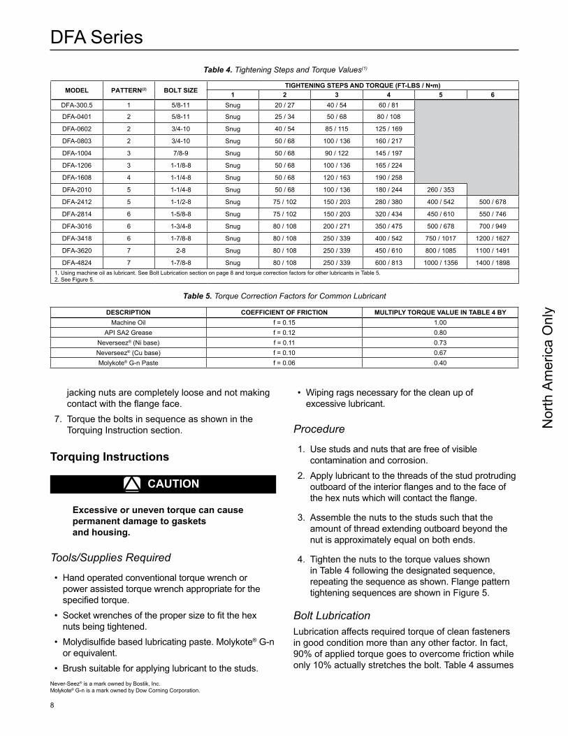
MODEL PATTErn(2) BOLT SiZETiGHTEninG STEPS AnD TOrQUE (FT-LBS / N•m)
1 2 3 4 5 6DFA-300.5 1 5/8-11 Snug 20 / 27 40 / 54 60 / 81
DFA-0401 2 5/8-11 Snug 25 / 34 50 / 68 80 / 108
DFA-0602 2 3/4-10 Snug 40 / 54 85 / 115 125 / 169
DFA-0803 2 3/4-10 Snug 50 / 68 100 / 136 160 / 217
DFA-1004 3 7/8-9 Snug 50 / 68 90 / 122 145 / 197
DFA-1206 3 1-1/8-8 Snug 50 / 68 100 / 136 165 / 224
DFA-1608 4 1-1/4-8 Snug 50 / 68 120 / 163 190 / 258
DFA-2010 5 1-1/4-8 Snug 50 / 68 100 / 136 180 / 244 260 / 353
DFA-2412 5 1-1/2-8 Snug 75 / 102 150 / 203 280 / 380 400 / 542 500 / 678
DFA-2814 6 1-5/8-8 Snug 75 / 102 150 / 203 320 / 434 450 / 610 550 / 746
DFA-3016 6 1-3/4-8 Snug 80 / 108 200 / 271 350 / 475 500 / 678 700 / 949
DFA-3418 6 1-7/8-8 Snug 80 / 108 250 / 339 400 / 542 750 / 1017 1200 / 1627
DFA-3620 7 2-8 Snug 80 / 108 250 / 339 450 / 610 800 / 1085 1100 / 1491
DFA-4824 7 1-7/8-8 Snug 80 / 108 250 / 339 600 / 813 1000 / 1356 1400 / 18981. Using machine oil as lubricant. See Bolt Lubrication section on page 8 and torque correction factors for other lubricants in Table 5.2. See Figure 5.
Table 4. Tightening Steps and Torque Values(1)
DESCriPTiOn COEFFiCiEnT OF FriCTiOn MULTiPLY TOrQUE VALUE in TABLE 4 BYMachine Oil f = 0.15 1.00
API SA2 Grease f = 0.12 0.80Neverseez® (Ni base) f = 0.11 0.73Neverseez® (Cu base) f = 0.10 0.67Molykote® G-n Paste f = 0.06 0.40
Table 5. Torque Correction Factors for Common Lubricant
Never-Seez® is a mark owned by Bostik, Inc.Molykote® G-n is a mark owned by Dow Corning Corporation.
jacking nuts are completely loose and not making contact with the flange face.
7. Torque the bolts in sequence as shown in the Torquing Instruction section.
Torquing instructions
CAUTiOn
Excessive or uneven torque can cause permanent damage to gaskets and housing.
Tools/Supplies Required
• Hand operated conventional torque wrench or power assisted torque wrench appropriate for the specified torque.
• Socket wrenches of the proper size to fit the hex nuts being tightened.
• Molydisulfide based lubricating paste. Molykote® G-n or equivalent.
• Brush suitable for applying lubricant to the studs.
• Wiping rags necessary for the clean up of excessive lubricant.
Procedure
1. Use studs and nuts that are free of visible contamination and corrosion.
2. Apply lubricant to the threads of the stud protruding outboard of the interior flanges and to the face of the hex nuts which will contact the flange.
3. Assemble the nuts to the studs such that the amount of thread extending outboard beyond the nut is approximately equal on both ends.
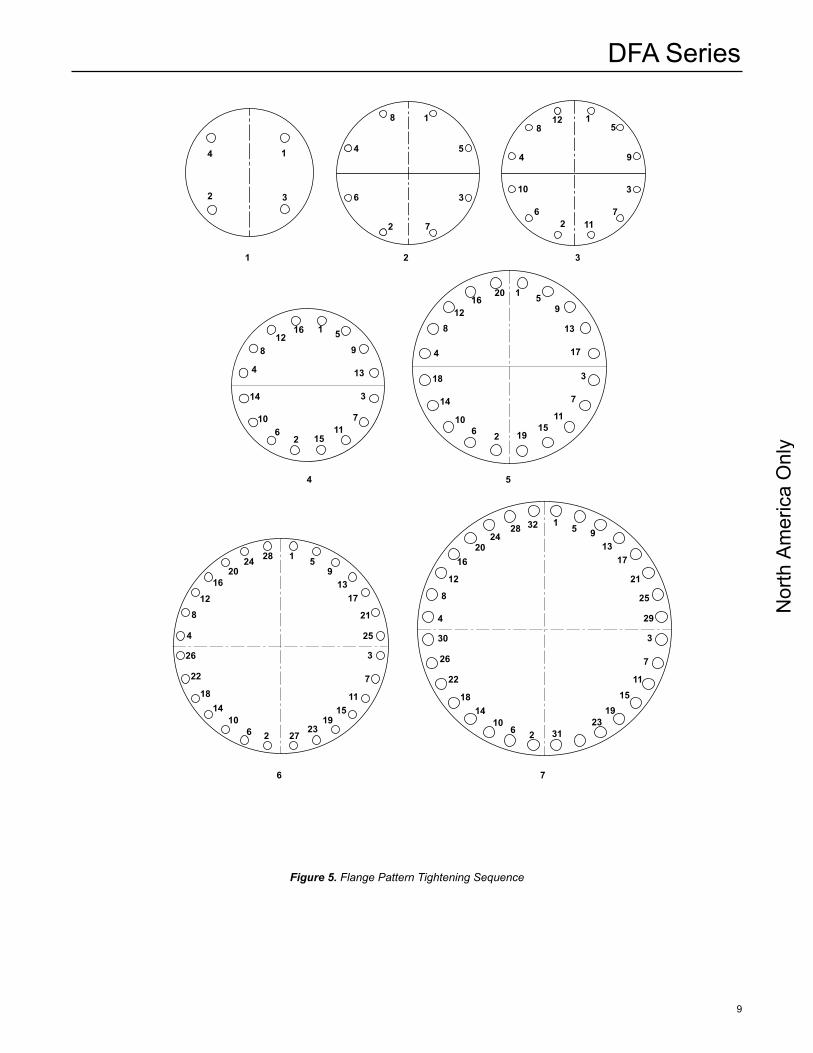
4. Tighten the nuts to the torque values shown in Table 4 following the designated sequence, repeating the sequence as shown. Flange pattern tightening sequences are shown in Figure 5.
Bolt LubricationLubrication affects required torque of clean fasteners in good condition more than any other factor. In fact, 90% of applied torque goes to overcome friction while only 10% actually stretches the bolt. Table 4 assumes
Nor
th A
mer
ica
Onl
y
DFA Series
9
Figure 5. Flange Pattern Tightening Sequence
1 2
54
76
3
1
2 3
4
1
2
3
4 5
6
7
8 1
2
3
4
5
6 7
8
9
10
11
12
1
2
3
4
5
7
8 9
1011
12
13
14
15
16
6
1
3
2
4
5
6
7
8
9
10 11
1213
14
15
16
17
18
19
20
28
28
1
1
5
5
913
17
21
25
913
17
21
25
29
3
3
7
7
11
11
1515
1919
2323
27 316 62 210 10
14 14
18 18
22 22
26 26
30
32
4
4
8
812
1216
1620
2024
24
Nor
th A
mer
ica
Onl
y
DFA Series
10
that only machine oil is used as a lubricant. Table 5 shows a list of several common lubricants and their effect on torque required to stretch bolts to 50% of their yield strength. Most are available from local bearing distributors.
recommended Spare PartsFor installations that require frequent maintenance and minimum downtime, it is recommended that the user purchase a spare element assembly and several spare element gaskets. The spare element assembly can be installed immediately and the dirty assembly can then be cleaned and stored as a spare for the next maintenance interval.
HOUSinG Carbon Steel 304 Stainless Steel Carbon Steel 316 Stainless Steel
FLAME CELL 304 Stainless Steel 304 Stainless Steel 316 Stainless Steel 316 Stainless Steel
MODEL PArT nUMBEr
DFA(E)-0401 9006032 9006069 9006066 9006082
DFA(E)-0602 9006033 9006070 9006040 9006083
DFA(E)-0803 9006038 9006071 9006034 9006084
DFA(E)-1004 9006035 9006072 9006078 9006053
DFA(E)-1206 9006020 9006047 9006037 9006024
DFA(E)-1608 9006012 9006010 9006041 9006085
DFA(E)-2010 9006013 9006073 9006062 9006011
DFA(E)-2412 9006009 9006074 9006065 9006049
DFA(E)-2814 9006021 9006075 9006079 9006086
DFA(E)-3016 9006029 9006076 9006063 9006087
DFA(E)-3418 9006067 9006008 9006080 9006088
DFA(E)-3620 9006068 9006077 9006081 9006089
Table 7. Replacement Element Assembly Part Numbers (Group D (IIA) Gas)
Parts List
MODELPArT nUMBEr
Standard Gasket (Compressed Fiber) High Temperature Gasket (Graphite Base)
DFA(E)-0401 7008122 7049222
DFA(E)-0602 7008123 7049223
DFA(E)-0803 7008135 7049235
DFA(E)-1004 7008105 7049205
DFA(E)-1206 7008106 7049206
DFA(E)-1608 7008137 7049237
DFA(E)-2010 7008138 7049238
DFA(E)-2412 7008139 7049239
DFA(E)-2814 7008140 7049240
DFA(E)-3016 7008141 7049241
DFA(E)-3418 7008142 7049242
DFA(E)-3620 7008143 7049243
1. Two (2) required per assembly.
Table 6. Replacement Element Assembly Gasket Part Numbers(1)
noteElement gaskets must be replaced each time the cell assembly is loosened and removed to ensure a gas tight seal.
Parts OrderingWhen corresponding with your local Sales Office about this equipment, always reference the equipment serial number stamped on the nameplate.
When ordering replacement parts, specify the complete 7-character part number of each required part as found in the following parts list.
Nor
th A
mer
ica
Onl
y
DFA Series
11
Table 8. Replacement Element Assembly Part Numbers(1) (Group C (IIB3) Gas)
HOUSinG Carbon Steel 304 Stainless Steel Carbon Steel 316 Stainless Steel
FLAME CELL 304 Stainless Steel 304 Stainless Steel 316 Stainless Steel 316 Stainless Steel
MODEL PArT nUMBEr
DFA(E)-0401 9032203 9032204 9032205 9032206
DFA(E)-0602 9006058 9032207 9006017 9006022
DFA(E)-0803 9006042 9032208 9006044 9006060
DFA(E)-1004 9006045 9006048 9006016 9032209
DFA(E)-1206 9006036 9032210 9006002 9006043
DFA(E)-1608 9006015 9006004 9032211 9006023
DFA(E)-2010 9006025 9032212 9032213 9006064
DFA(E)-2412 9006026 9032214 9032215 9032216
DFA(E)-2814 9006019 9032217 9032218 9006005
DFA(E)-3016 9032219 9032220 9006006 9032221
DFA(E)-3418 9032222 9032223 9032224 9032225
DFA(E)-3620 9032226 9032227 9032228 9032229
1. These are not ATEX or USCG approved and may not be used for applications requiring these certifications.
Table 9. Replacement Element Assembly Part Numbers(1) (Group B Gas)
HOUSinG Carbon Steel 304 Stainless Steel Carbon Steel 316 Stainless Steel
FLAME CELL 304 Stainless Steel 304 Stainless Steel 316 Stainless Steel 316 Stainless Steel
MODEL PArT nUMBEr
DFA(E)-0300.5 - - - - - - - - - - - - - - - - - - - - - 9031700
DFA(E)-0401 9006090 9006091 9006092 9006014
DFA(E)-0602 9006055 9006093 9006028 9006094
DFA(E)-0803 9006095 9006096 9006097 9006059
DFA(E)-1004 9006007 9006098 9006099 9006027
DFA(E)-1206 9006031 9006057 9032201 9032202
1. These are not ATEX or USCG approved and may not be used for applications requiring these certifications.
Nor
th A
mer
ica
Onl
y
DFA Series
©Emerson Process Management Regulator Technologies Tulsa, LLC, 2015, 2016, Rev. E; All Rights Reserved
The Emerson logo is a trademark and service mark of Emerson Electric Co. All other marks are the property of their prospective owners. Enardo is a mark owned by Regulator Technologies Tulsa, LLC, a business of Emerson Process Management.
The contents of this publication are presented for informational purposes only, and while every effort has been made to ensure their accuracy, they are not to be construed as warranties or guarantees, express or implied, regarding the products or services described herein or their use or applicability. We reserve the right to modify or improve the designs or specifications of such products at any time without notice.
Emerson Process Management Regulator Technologies Tulsa, LLC does not assume responsibility for the selection, use or maintenance of any product. Responsibility for proper selection, use and maintenance of any Emerson Process Management Regulator Technologies Tulsa, LLC product remains solely with the purchaser.
For further information visit www.enardo.com
Emerson Process ManagementRegulator Technologies Tulsa, LLC
9932 East 58th StreetTulsa, Oklahoma 74146 USA
Tel: +1 918 662 6161Fax: +1 918 662 0004