Embed Size (px)
Citation preview

Device: PLT-1003
This document Version: 1.0
Date: October 2010
Description: USB to Serial interface and USB development platform

PLT-1003 datasheet – Page 2
www.embeddedadventures.com
Table of Contents
Introduction......................................................................................................... 3
Features .............................................................................................................. 3
Hackability ........................................................................................................... 3
Construction ........................................................................................................ 3
Connections ......................................................................................................... 4
Power ................................................................................................................. 4
Buttons ............................................................................................................... 4
Indicators ............................................................................................................ 4
Schematic............................................................................................................ 5
Microcontroller.................................................................................................. 5
Connections ..................................................................................................... 6
PCB ..................................................................................................................... 7
Installation .......................................................................................................... 7
Changing the COM port number ...................................................................... 13
Versions ............................................................................................................ 15
PLT-1003 datasheet – Page 3
www.embeddedadventures.com
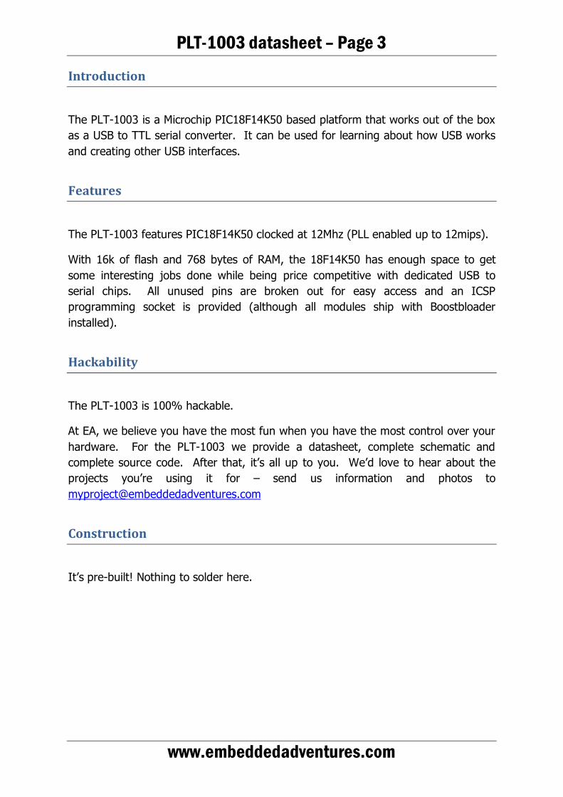
Introduction
The PLT-1003 is a Microchip PIC18F14K50 based platform that works out of the box as a USB to TTL serial converter. It can be used for learning about how USB works and creating other USB interfaces.
Features
The PLT-1003 features PIC18F14K50 clocked at 12Mhz (PLL enabled up to 12mips).
With 16k of flash and 768 bytes of RAM, the 18F14K50 has enough space to get some interesting jobs done while being price competitive with dedicated USB to serial chips. All unused pins are broken out for easy access and an ICSP programming socket is provided (although all modules ship with Boostbloader installed).
Hackability
The PLT-1003 is 100% hackable.
At EA, we believe you have the most fun when you have the most control over your hardware. For the PLT-1003 we provide a datasheet, complete schematic and complete source code. After that, it’s all up to you. We’d love to hear about the projects you’re using it for – send us information and photos to [email protected]
Construction
It’s pre-built! Nothing to solder here.

PLT-1003 datasheet – Page 4
www.embeddedadventures.com
Connections
The PLT-1003 has three connection ports.
SERIAL TTL level serial port ICSP Programming port for PIC
EXPANSION Breakout of all unused pins
Power
The PLT-1003 happy slurps power from the USB port and can provide either 3.3v or 5v depending on the jumper setting.
Buttons
The PLT-1003 has two buttons.
One connected to RC0, the other is connected to RC1. Both include a capacitor to reduce debounce noise, and a pull up resistor. To check for a button press, set the appropriate pin as an input and look for it to go to 0 (press) and then back to 1 (release). RC0 and RC1 pins are also available as interrupt pins.
Indicators
The PLT-1002 has three LEDs connected to RC5, RC6 and RC7 (LED1, LED2 and LED3 respectively). LED 1 (red) will light during Boostbloader initialisation. You can use these for your own nefarious purposes, although predictably the default firmware uses LED2 (green) and LED3 (yellow) for Rx and Tx.

PLT-1003 datasheet – Page 5
www.embeddedadventures.com
Schematic
Microcontroller
C3, C4 and 12Mhz crystal allow the PIC to run at 64Mhz (via the PLL), or 12mips. C1 is a power supply bypass for the PIC.
C2 is required for USB operation (USB data actually runs at 3.3v, despite its 5v power provision).

PLT-1003 datasheet – Page 6
www.embeddedadventures.com
Connections
The Expansion board breaks out all remaining pins that are not used elsewhere. You have access to RC2, RC3, RC4, RB4, and RB6 and an extra handy ground connection. This allows connection to external devices such as humidity or pressure sensors to expand the capability of the board, or to provide other serial pin outs such as RTS/DTS and DCD/DTR.
USB is provided as standard micro-USB.
The Serial port provides TX-O (out from the board) and RX-I (in to the board), along with ground and Vcc connections if required. Note that if you are connecting a serial connection to the board, you will typically connect TX on the PLT-1003 to RX on your external serial connection, as well is TX on the PLT-1003 to RX externally. That is, you swap TX and RX between the PLT-1003 and another device. That other device may even be another PLT-1003 (yes, you can reprogram a PLT-1003 using another one!)
The ICSP port allows access to PGC (RA1), PGD (RA0) and MCLR (RA3). If you’re not actually using the USB connection, these pins are available for other uses. Due to the fact these pins are also shared with USB D+/D- it’s important to unplug your ICSP programmer, if you use one, while using USB.
ICSP allows you to program the 18F14K50 using the Pickit or ICD compilers from Microchip. Typically, this is only necessary in order to get a bootloader on the microcontroller, and the Boostbloader is supplied preloaded on all modules.

PLT-1003 datasheet – Page 7
www.embeddedadventures.com
PCB
The board is provided pre-assembled, but we may provide it in a kit form in future if there is demand for it.
Installation
These instructions will get you up and running in about 30 seconds with Windows 7 or Vista.
PLT-1003 datasheet – Page 8
www.embeddedadventures.com
The first time you install your USB2Serial board, it will flash the three LEDs in a hypnotic pattern, giving a clear indication of the happiness the board feels at being powered up and ready to do its thing.
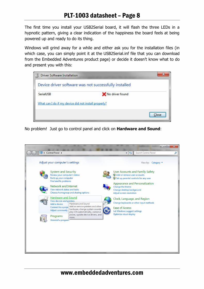
Windows will grind away for a while and either ask you for the installation files (in which case, you can simply point it at the USB2Serial.inf file that you can download from the Embedded Adventures product page) or decide it doesn’t know what to do and present you with this:
No problem! Just go to control panel and click on Hardware and Sound:

PLT-1003 datasheet – Page 9
www.embeddedadventures.com
You’ll now see the following screen. Click on Device Manager.
Windows will ask you if you want to allow this program to make changes to your computer. Say yes, and then you should see this list of devices.

PLT-1003 datasheet – Page 10
www.embeddedadventures.com
Serial2USB device will be listed there under Other Devices for the moment, since windows doesn’t know what it is yet.
Just right click on Serial2USB and choose Update Driver Software

PLT-1003 datasheet – Page 11
www.embeddedadventures.com
You want to Browse my computer for driver software
Now you can enter directory of wherever you’ve put the USB2Serial.inf file (or press browse to find it).
PLT-1003 datasheet – Page 12
www.embeddedadventures.com
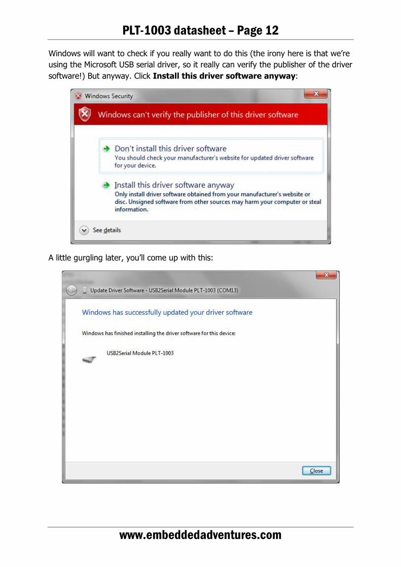
Windows will want to check if you really want to do this (the irony here is that we’re using the Microsoft USB serial driver, so it really can verify the publisher of the driver software!) But anyway. Click Install this driver software anyway:
A little gurgling later, you’ll come up with this:

PLT-1003 datasheet – Page 13
www.embeddedadventures.com
Whoohoo! We’re done. Wasn’t that hard, was it? Please note that once you’ve installed it, the flashing will stop and unless you’ve connected it to something, the green “RX” LED will be continuously lit.
Changing the COM port number
If you want to change the COM port number used by the USB2Serial board, simply go back into Device manager:
(You can see here I have two COM ports on my computer, one is a boring Prolific USB 2 serial port and the other is the PLT-1003).
PLT-1003 datasheet – Page 14
www.embeddedadventures.com
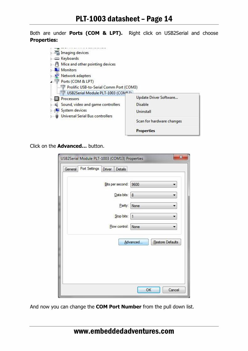
Both are under Ports (COM & LPT). Right click on USB2Serial and choose Properties:
Click on the Advanced… button.
And now you can change the COM Port Number from the pull down list.

PLT-1003 datasheet – Page 15
www.embeddedadventures.com
Don’t worry if it says (in use) after the COM port number. That just means that some other device, at some time, has used that COM port number. You can duplicate them, quite happily. If you actually do have (for example) a COM 1 already on your system, then obviously you can’t open both of them. Often Bluetooth drivers etc create bunches of COM ports.
Versions
Version Date Comments Version 1.0 10 Oct 2010 Initial Version for board v1.1AB