Embed Size (px)
Citation preview
Mitsubishi Heavy Industries Technical Review Vol. 47 No. 4 (December 2010) 1
*1 Turbocharger Engineering Department, General Machinery & Special Vehicle Headquarters
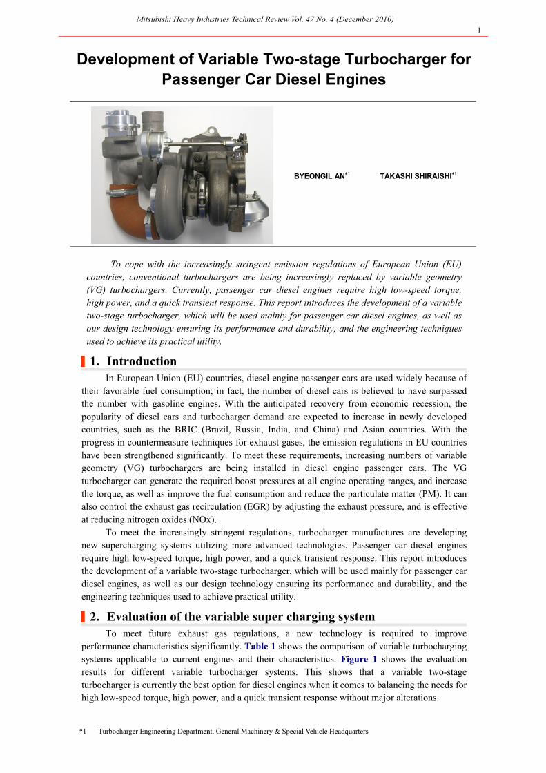
Development of Variable Two-stage Turbocharger for Passenger Car Diesel Engines
BYEONGIL AN*1 TAKASHI SHIRAISHI*1
To cope with the increasingly stringent emission regulations of European Union (EU) countries, conventional turbochargers are being increasingly replaced by variable geometry (VG) turbochargers. Currently, passenger car diesel engines require high low-speed torque, high power, and a quick transient response. This report introduces the development of a variable two-stage turbocharger, which will be used mainly for passenger car diesel engines, as well as our design technology ensuring its performance and durability, and the engineering techniques used to achieve its practical utility.
|1. Introduction
In European Union (EU) countries, diesel engine passenger cars are used widely because of their favorable fuel consumption; in fact, the number of diesel cars is believed to have surpassed the number with gasoline engines. With the anticipated recovery from economic recession, the popularity of diesel cars and turbocharger demand are expected to increase in newly developed countries, such as the BRIC (Brazil, Russia, India, and China) and Asian countries. With the progress in countermeasure techniques for exhaust gases, the emission regulations in EU countries have been strengthened significantly. To meet these requirements, increasing numbers of variable geometry (VG) turbochargers are being installed in diesel engine passenger cars. The VG turbocharger can generate the required boost pressures at all engine operating ranges, and increase the torque, as well as improve the fuel consumption and reduce the particulate matter (PM). It can also control the exhaust gas recirculation (EGR) by adjusting the exhaust pressure, and is effective at reducing nitrogen oxides (NOx).
To meet the increasingly stringent regulations, turbocharger manufactures are developing new supercharging systems utilizing more advanced technologies. Passenger car diesel engines require high low-speed torque, high power, and a quick transient response. This report introduces the development of a variable two-stage turbocharger, which will be used mainly for passenger car diesel engines, as well as our design technology ensuring its performance and durability, and the engineering techniques used to achieve practical utility.
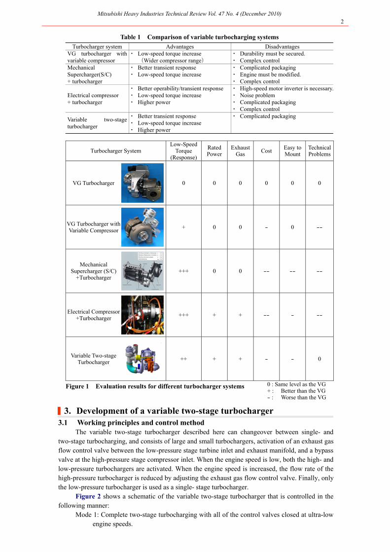
|2. Evaluation of the variable super charging system To meet future exhaust gas regulations, a new technology is required to improve
performance characteristics significantly. Table 1 shows the comparison of variable turbocharging systems applicable to current engines and their characteristics. Figure 1 shows the evaluation results for different variable turbocharger systems. This shows that a variable two-stage turbocharger is currently the best option for diesel engines when it comes to balancing the needs for high low-speed torque, high power, and a quick transient response without major alterations.
Mitsubishi Heavy Industries Technical Review Vol. 47 No. 4 (December 2010) 2
Table 1 Comparison of variable turbocharging systems Turbocharger system Advantages Disadvantages VG turbocharger with
variable compressor ・ Low-speed torque increase (Wider compressor range)
・ Durability must be secured. ・ Complex control
Mechanical Supercharger(S/C) + turbocharger
・ Better transient response ・ Low-speed torque increase
・ Complicated packaging ・ Engine must be modified. ・ Complex control
Electrical compressor + turbocharger
・ Better operability/transient response ・ Low-speed torque increase ・ Higher power
・ High-speed motor inverter is necessary.・ Noise problem ・ Complicated packaging ・ Complex control
Variable two-stage turbocharger
・ Better transient response ・ Low-speed torque increase ・ Higher power
・ Complicated packaging
Turbocharger System Low-Speed
Torque (Response)
Rated Power
Exhaust Gas
Cost Easy to Mount
Technical Problems
VG Turbocharger 0 0 0 0 0 0
VG Turbocharger with Variable Compressor
+ 0 0 - 0 --
Mechanical Supercharger (S/C)
+Turbocharger +++ 0 0 -- -- --
Electrical Compressor+Turbocharger
+++ + + -- - --
Variable Two-stage Turbocharger ++ + + - - 0
Figure 1 Evaluation results for different turbocharger systems 0 : Same level as the VG + : Better than the VG - : Worse than the VG
|3. Development of a variable two-stage turbocharger 3.1 Working principles and control method
The variable two-stage turbocharger described here can changeover between single- and two-stage turbocharging, and consists of large and small turbochargers, activation of an exhaust gas flow control valve between the low-pressure stage turbine inlet and exhaust manifold, and a bypass valve at the high-pressure stage compressor inlet. When the engine speed is low, both the high- and low-pressure turbochargers are activated. When the engine speed is increased, the flow rate of the high-pressure turbocharger is reduced by adjusting the exhaust gas flow control valve. Finally, only the low-pressure turbocharger is used as a single- stage turbocharger.
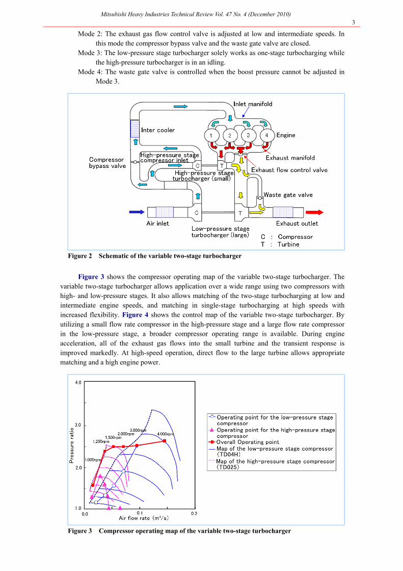
Figure 2 shows a schematic of the variable two-stage turbocharger that is controlled in the following manner:
Mode 1: Complete two-stage turbocharging with all of the control valves closed at ultra-low engine speeds.
Mitsubishi Heavy Industries Technical Review Vol. 47 No. 4 (December 2010) 3
Mode 2: The exhaust gas flow control valve is adjusted at low and intermediate speeds. In this mode the compressor bypass valve and the waste gate valve are closed.
Mode 3: The low-pressure stage turbocharger solely works as one-stage turbocharging while the high-pressure turbocharger is in an idling.
Mode 4: The waste gate valve is controlled when the boost pressure cannot be adjusted in Mode 3.
Figure 2 Schematic of the variable two-stage turbocharger
Figure 3 shows the compressor operating map of the variable two-stage turbocharger. The variable two-stage turbocharger allows application over a wide range using two compressors with high- and low-pressure stages. It also allows matching of the two-stage turbocharging at low and intermediate engine speeds, and matching in single-stage turbocharging at high speeds with increased flexibility. Figure 4 shows the control map of the variable two-stage turbocharger. By utilizing a small flow rate compressor in the high-pressure stage and a large flow rate compressor in the low-pressure stage, a broader compressor operating range is available. During engine acceleration, all of the exhaust gas flows into the small turbine and the transient response is improved markedly. At high-speed operation, direct flow to the large turbine allows appropriate matching and a high engine power.
Figure 3 Compressor operating map of the variable two-stage turbocharger
Mitsubishi Heavy Industries Technical Review Vol. 47 No. 4 (December 2010) 4
Operating
area
Exhaust flow control
valve
Compressor bypass valve
Waste gate valve
Mode 1 Closed Closed Closed
Mode 2 Controlled Closed Closed
Mode 3 Open Open Closed
Mode 4 Open Open Controlled
Figure 4 Control map of the variable two-stage turbocharger
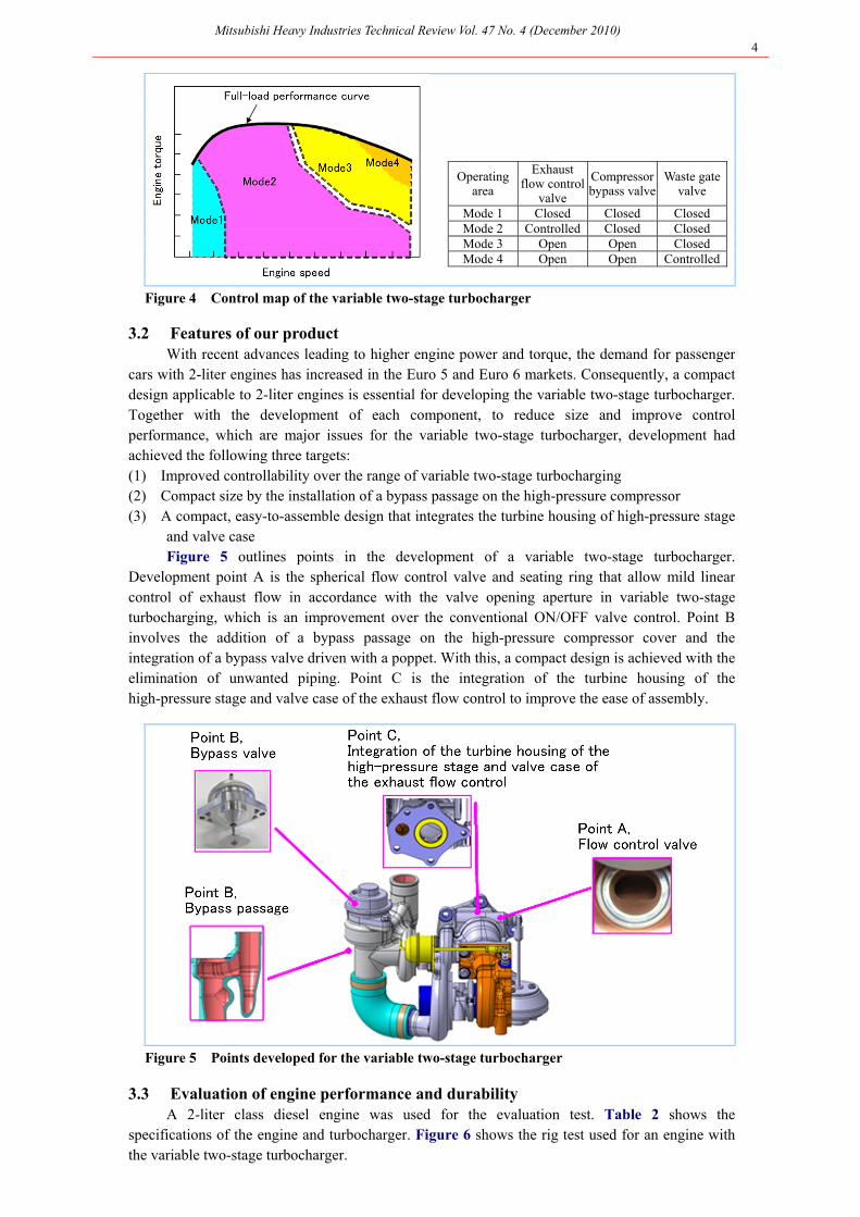
3.2 Features of our product With recent advances leading to higher engine power and torque, the demand for passenger
cars with 2-liter engines has increased in the Euro 5 and Euro 6 markets. Consequently, a compact design applicable to 2-liter engines is essential for developing the variable two-stage turbocharger. Together with the development of each component, to reduce size and improve control performance, which are major issues for the variable two-stage turbocharger, development had achieved the following three targets: (1) Improved controllability over the range of variable two-stage turbocharging (2) Compact size by the installation of a bypass passage on the high-pressure compressor (3) A compact, easy-to-assemble design that integrates the turbine housing of high-pressure stage
and valve case Figure 5 outlines points in the development of a variable two-stage turbocharger.
Development point A is the spherical flow control valve and seating ring that allow mild linear control of exhaust flow in accordance with the valve opening aperture in variable two-stage turbocharging, which is an improvement over the conventional ON/OFF valve control. Point B involves the addition of a bypass passage on the high-pressure compressor cover and the integration of a bypass valve driven with a poppet. With this, a compact design is achieved with the elimination of unwanted piping. Point C is the integration of the turbine housing of the high-pressure stage and valve case of the exhaust flow control to improve the ease of assembly.
Figure 5 Points developed for the variable two-stage turbocharger
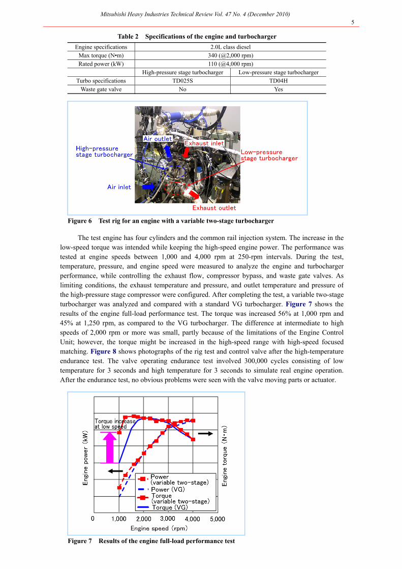
3.3 Evaluation of engine performance and durability A 2-liter class diesel engine was used for the evaluation test. Table 2 shows the
specifications of the engine and turbocharger. Figure 6 shows the rig test used for an engine with the variable two-stage turbocharger.
Mitsubishi Heavy Industries Technical Review Vol. 47 No. 4 (December 2010) 5
Table 2 Specifications of the engine and turbocharger
Engine specifications 2.0L class diesel
Max torque (N•m) 340 (@2,000 rpm)
Rated power (kW) 110 (@4,000 rpm)
High-pressure stage turbocharger Low-pressure stage turbocharger
Turbo specifications TD025S TD04H
Waste gate valve No Yes
Figure 6 Test rig for an engine with a variable two-stage turbocharger
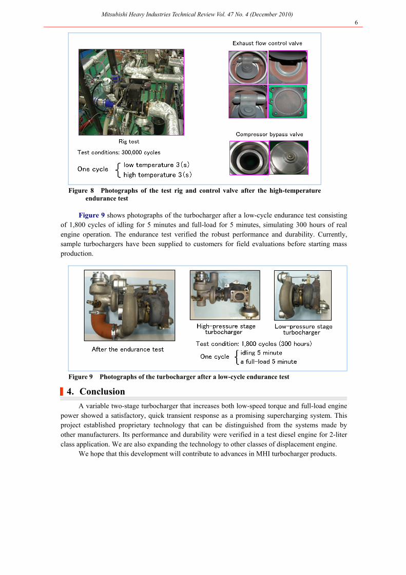
The test engine has four cylinders and the common rail injection system. The increase in the low-speed torque was intended while keeping the high-speed engine power. The performance was tested at engine speeds between 1,000 and 4,000 rpm at 250-rpm intervals. During the test, temperature, pressure, and engine speed were measured to analyze the engine and turbocharger performance, while controlling the exhaust flow, compressor bypass, and waste gate valves. As limiting conditions, the exhaust temperature and pressure, and outlet temperature and pressure of the high-pressure stage compressor were configured. After completing the test, a variable two-stage turbocharger was analyzed and compared with a standard VG turbocharger. Figure 7 shows the results of the engine full-load performance test. The torque was increased 56% at 1,000 rpm and 45% at 1,250 rpm, as compared to the VG turbocharger. The difference at intermediate to high speeds of 2,000 rpm or more was small, partly because of the limitations of the Engine Control Unit; however, the torque might be increased in the high-speed range with high-speed focused matching. Figure 8 shows photographs of the rig test and control valve after the high-temperature endurance test. The valve operating endurance test involved 300,000 cycles consisting of low temperature for 3 seconds and high temperature for 3 seconds to simulate real engine operation. After the endurance test, no obvious problems were seen with the valve moving parts or actuator.
Figure 7 Results of the engine full-load performance test
Mitsubishi Heavy Industries Technical Review Vol. 47 No. 4 (December 2010) 6
Figure 8 Photographs of the test rig and control valve after the high-temperature
endurance test
Figure 9 shows photographs of the turbocharger after a low-cycle endurance test consisting of 1,800 cycles of idling for 5 minutes and full-load for 5 minutes, simulating 300 hours of real engine operation. The endurance test verified the robust performance and durability. Currently, sample turbochargers have been supplied to customers for field evaluations before starting mass production.
Figure 9 Photographs of the turbocharger after a low-cycle endurance test
|4. Conclusion
A variable two-stage turbocharger that increases both low-speed torque and full-load engine power showed a satisfactory, quick transient response as a promising supercharging system. This project established proprietary technology that can be distinguished from the systems made by other manufacturers. Its performance and durability were verified in a test diesel engine for 2-liter class application. We are also expanding the technology to other classes of displacement engine.
We hope that this development will contribute to advances in MHI turbocharger products.