Embed Size (px)
Citation preview
Development of the high heat flux component for a fusion reactor
M Tokitani a Y Hamaji a Y Hiraoka b S Masuzaki a H Tamura a H Noto a T Tanaka a T Muroga a A Sagara a
and FFHR Design Group a
a National Institute for Fusion Scienceb Okayama University of Science
4th meeting of the Radiation Damage In Accelerator Target Environments (4th RaDIATE)
125
Contents
225
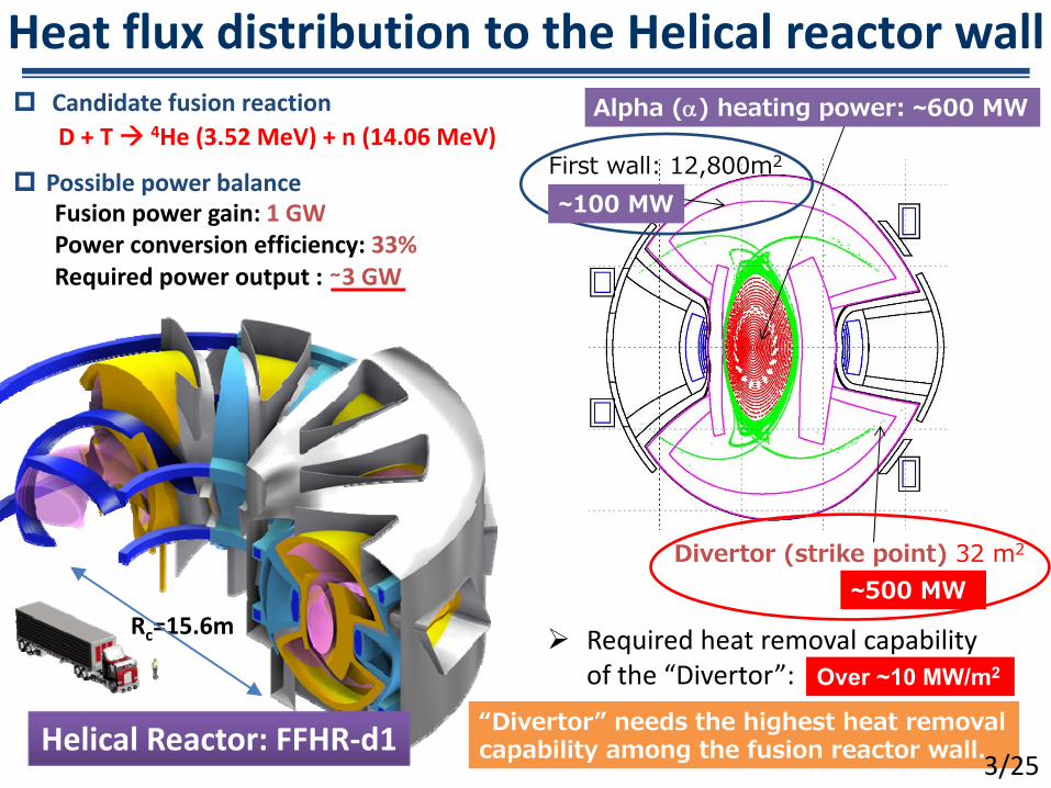
Heat flux distribution to the Helical reactor wall
Required heat removal capability of the ldquoDivertorrdquo
Alpha () heating power ~600 MW
Divertor (strike point) 32 m2
Possible power balance
ldquoDivertorrdquo needs the highest heat removal capability among the fusion reactor wall
~500 MW
Over ~10 MWm2
Fusion power gain 1 GWPower conversion efficiency 33Required power output sim3 GW
D + T 4He (352 MeV) + n (1406 MeV) Candidate fusion reaction
Helical Reactor FFHR‐d1
First wall 12800m2
~100 MW
325
Rc=156m
Contents
425
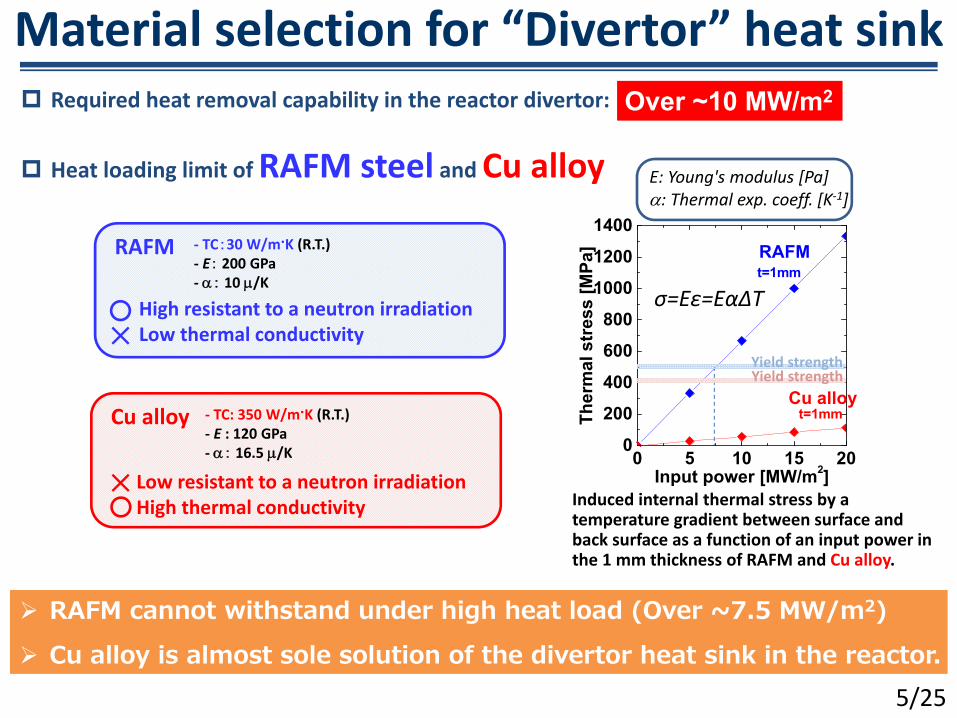
Material selection for ldquoDivertorrdquo heat sink Required heat removal capability in the reactor divertor
0 5 10 15 200
200400600800
100012001400
Cu alloy
RAFM
t=1mm
Ther
mal
str
ess
[MPa
]
Input power [MWm2]
t=1mm
Induced internal thermal stress by a temperature gradient between surface and back surface as a function of an input power in the 1 mm thickness of RAFM and Cu alloy
σ=Eε=EαΔT
Heat loading limit of RAFM steel and Cu alloy
RAFM cannot withstand under high heat load (Over ~75 MWm2) Cu alloy is almost sole solution of the divertor heat sink in the reactor
‐ TC30 WmK (RT)‐ E 200 GPa‐ 10 K
‐ TC 350 WmK (RT)‐ E 120 GPa‐ 165 K
E Youngs modulus [Pa] Thermal exp coeff [K‐1]
525
Over ~10 MWm2
Yield strengthYield strength
RAFM
High resistant to a neutron irradiationLow thermal conductivity
Cu alloy
Low resistant to a neutron irradiationHigh thermal conductivity
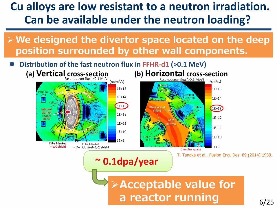
Cu alloys are low resistant to a neutron irradiation Can be available under the neutron loading
(a) Vertical cross‐section (b) Horizontal cross‐section Distribution of the fast neutron flux in FFHR‐d1 (gt01 MeV)
T Tanaka et al Fusion Eng Des 89 (2014) 1939
Acceptable value for a reactor running 625
We designed the divertor space located on the deep position surrounded by other wall components
~ 01dpayear
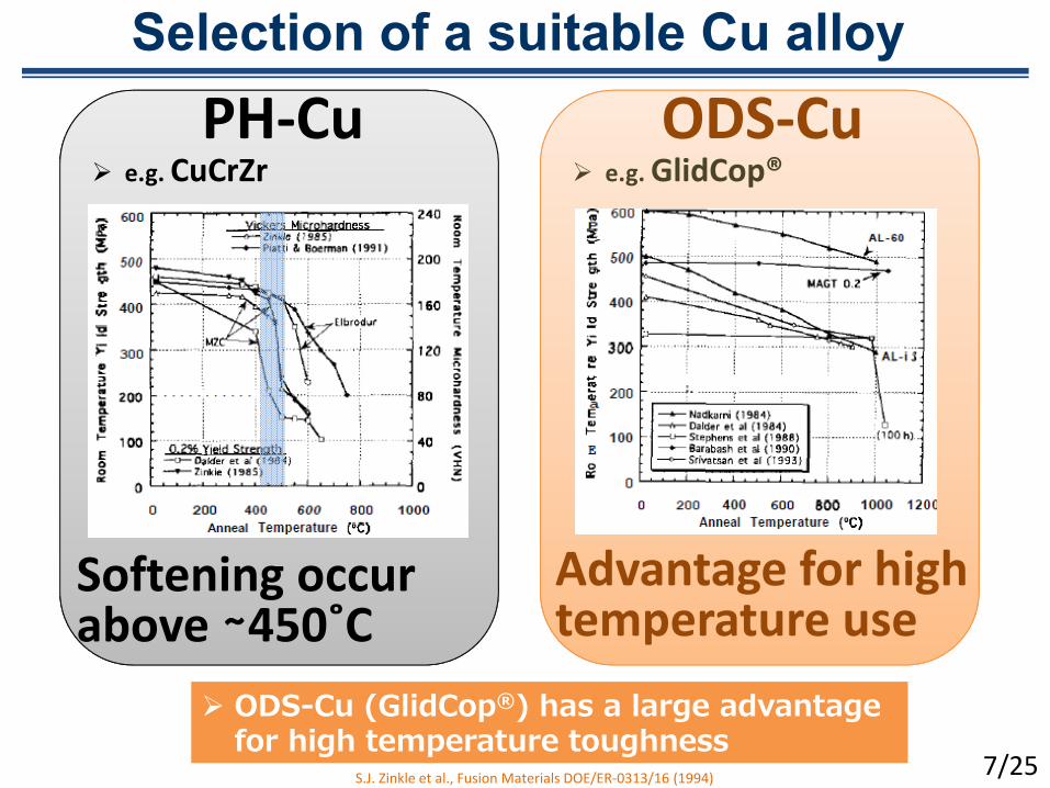
Selection of a suitable Cu alloy
SJ Zinkle et al Fusion Materials DOEER‐031316 (1994)
ODS-Cu (GlidCopreg) has a large advantage for high temperature toughness
eg GlidCopregODS‐Cu
eg CuCrZrPH‐Cu
Advantage for high temperature use
Softening occur above sim450˚C
725
Divertor plasma
Divertor armour
HeatParticle
Divertor plasma
ODS‐Cu(GlidCopreg)
W
Candidate armour structure
Coolant
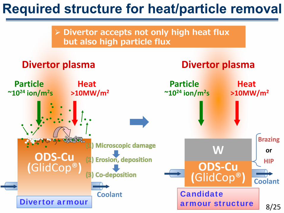
Required structure for heatparticle removal Divertor accepts not only high heat flux
but also high particle flux
~1024 ionm2s gt10MWm2HeatParticle
~1024 ionm2s gt10MWm2
BrazingorHIPODS‐Cu
(GlidCopreg)
825
Coolant
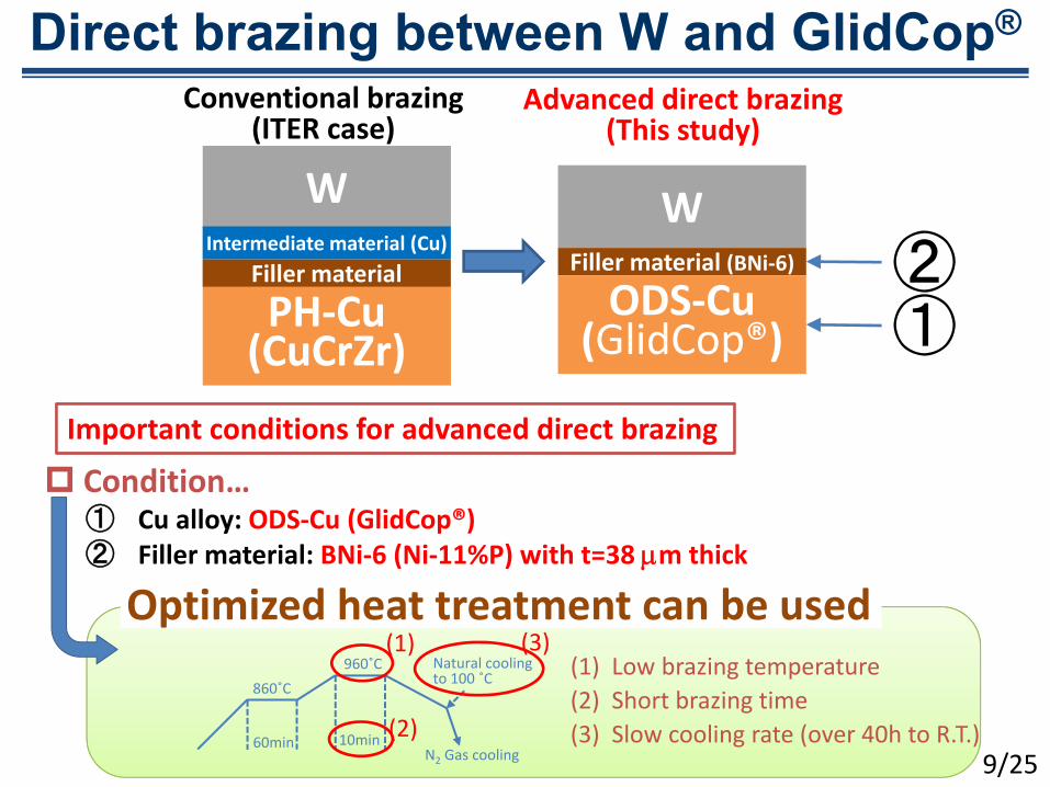
Direct brazing between W and GlidCopreg
PH‐Cu(CuCrZr)
WIntermediate material (Cu)
Filler material
W
Conventional brazing(ITER case)
Advanced direct brazing(This study)
Filler material (BNi‐6)
ODS‐Cu(GlidCopreg)
Conditionhellip① Cu alloy ODS‐Cu (GlidCopreg)② Filler material BNi‐6 (Ni‐11P) with t=38 m thick
Important conditions for advanced direct brazing
60min 10min
960˚C860˚C
N2 Gas cooling
Natural cooling to 100 ˚C
(1)
(2)
(3)(1) Low brazing temperature(2) Short brazing time(3) Slow cooling rate (over 40h to RT)
①②
Optimized heat treatment can be used
925
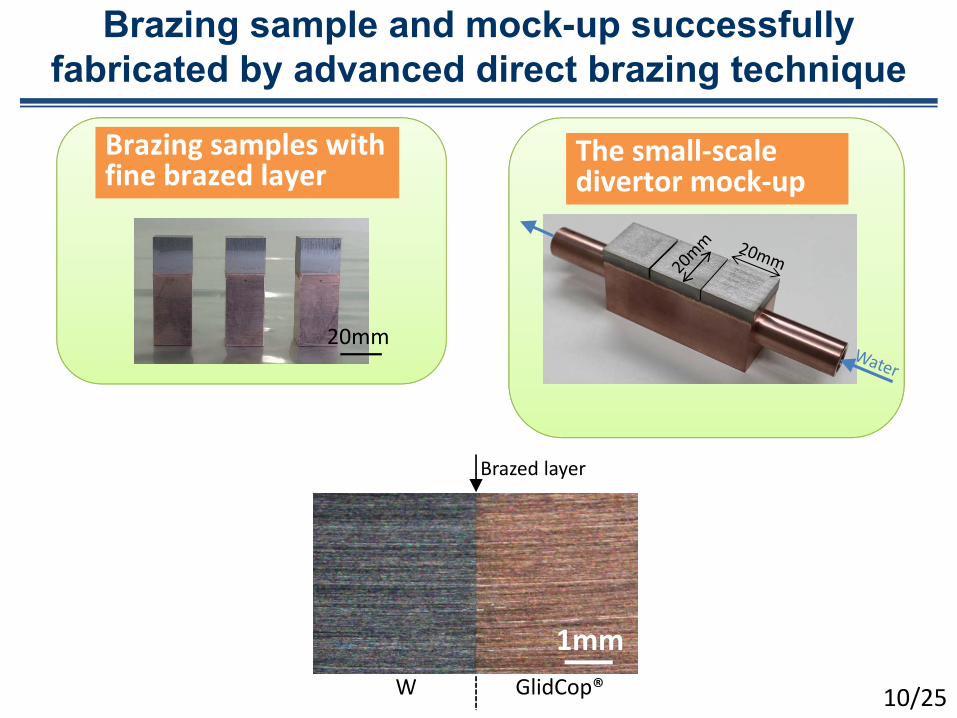
Brazing sample and mock-up successfully fabricated by advanced direct brazing technique
The small‐scale divertor mock‐up
Brazing samples with fine brazed layer
20mm
1mm
Brazed layer
GlidCopregW 1025
Bonding layer has an enough toughness
Ductile fracture properties was able to be obtained Bonding layer obtained a toughness
GlidCopreg W
Bonding layer
Schematic view of the deformation
Before
After0
50
100
150
200
Stre
ss [M
Pa]
Strain []
No 1No2
No3No4 No5
No6
025
(a) Room temperature
Results of the three point bending test
1125
Bonding strength at high temperature
Strength does not decrease so much even at a high temperatureDuctility and toughness are increased
0
50
100
150
200
Stre
ss [M
Pa]
Strain []
No 1No2
No3No4 No5
No6
025
(a)
0
50
100
150
200
Stre
ss [M
Pa]
Strain []
(b)
025
Room temperature
Toughness increased
1225
WBNi‐6GlidCopreg interlayer
Microstructural observation
20m
Fabricated by FIB
5m
Bonding layer
GlidCopregW
GlidCopregW
Extremely thin boding layer was successfully obtained
1325
0 3 6 9 12 150
100200300400500600700
Tem
pera
ture
[deg
]
Heat load [MWm2]
CH1 CH2 CH3 CH4 CH5 CH6 CH7 CH8 water out water in
Heat removal capability of the divertor mock-up Heat loading test in ACT2
ANSYS simulation at 15MWm2 steady state
The design of the WBNi‐6GlidCopreg showed an excellent heat removal capability for using in the FFHR‐d1 divertor
CH2CH5CH7
Simulation
˚C
Parameters‐ Filler material 60 WmK (50m thick)‐ Water 25˚C (Thermal transferred from Cu)‐ W 03
ACT2
CH1CH2
CH3
CH4CH5
CH6CH7
CH8
1425
Water cooling parameters‐ Pressure 03 MPa‐ Flow rate 52 Lmin‐ Temperature 25˚C
E‐gun
Chamber
specificationsparameters value unitmax output power 300 (100) kWacceleration voltage 40 kV DCmax current 75 Amax scanning area 300 x 300 mmspot size of e‐beam 〜10 mm
Developed for evaluation of heat removal capability of actively cooled components
Focused electron beam was scanned desired area by deflection lenses
The device can apply steady state reactor relevant heat flux (~20 MWm2 50 x 50 mm2)
Electron gun JEBG‐3000UB manufactured by JEOL Ltd
High heat flux facilityACT2 Active Cooling Test-stand 2
1525
bull Accelerated electron beam is focused as a Gaussian‐like profile (40 keV up to 75 A FWHM ~12 mm)
bull Target area is scanned by electro‐magnetic coils
(scan range 60 x 60 mm X 500 Hz Y 7143 Hz absorbed current 25 A on W)
(275‐28 MWm2 inside of the blue square)
Heat Flux distribution Temperature rise in scanning (calculation)
The beam profile(top) A melted spot of W irradiated for 01 s with 20 kW absorbed power (~200 MWm2 peak)(bottom)
Properties of the E-beam
1625By Y Hamaji
By Y Hamaji
Tested surface is heated homogeneously Equipped diagnostics
thermocouples (x 8) pyrometer 400‐2000 calorimetry temperature difference between inlet and outlet water absorbed beam current
side view top view
heated area
spot sizetested unit
e‐ beam
thermocouples
Example of an Experimental Set-up
1725
Contents
1825
Large Helical Device LHD
Divertor Carbon
First wallStainless Steel (SUS316L)
External diameter 135 mPlasma major radius 39 mPlasma minor radius 06 mPlasma volume 30 m3
Magnetic field 3 T
Plasma facing componentsTotal area of PFCs 780m2
First wall panels SUS316L (~730m2) 95Divertor plates Graphite (~50m2) 5 1925
1m
(d)
Replacement position
(a)
Flaking dusts accumulated near the C divertor
(b)
5mm
(c)
000 100 200 300 400 500 600 700 800 900 1000
keV
1000
0
150
300
450
600
750
900
1050
1200
1350
Counts
CO
Fe
FeK
esc
FeFe
Mixed‐material of C and Fe
Dust formation issues C divertor
Cross‐sectional microstructure of the dust by TEM
Very fine stratified mixed‐material structure with C and Fe 2025
Divertor tile(Isotropic graphite)
VPS‐W layer t=125m
The VPS-W with 125m thickness was coated on the IG tile
W‐Re multi layer
Replacement position
(a)
Flaky surface by C dust
(b)
Before campaign
ドーム下
W coated graphite divertor was installed
2125
(a)
(b)
Drastic improveldquoNo depositionrdquo
(c)
W coated graphite divertor
W coated divertor well worked for reduction of the flaking dust 2225
1cm
Melting and crack formation
Heat removal capability is not enough this structure 2325
Direct brazing component of WGlidCopreg
has been currently developing
WGlidCopreg divertor is expected for
1 Excellent heat removal capability2 Reduction of the dust formation3 Low retention of the H isotope
2425
Summary1 Development of the high heat flux component ldquoDivertorrdquo in fusion
reactor is one of the critical issues for realizing a fusion energy
2 The small divertor mock‐up of the WBNi‐6GlidCopreg was successfully developed in NIFS It showed an excellent heat removal capability Very thin bonding layer seems to contribute the excellent mechanical properties and heat removal capabilities
3 W coated graphite divertor tile was applied for demonstrating a reduction of the dust generation and a feasibility of the W coated surface Advantages of the W surface was demonstrated as a reduction of the dust formation
4 WGlidCopreg divertor has been developed to apply to the LHD experiment and towards a helical reactor
2525

Contents
225
Heat flux distribution to the Helical reactor wall
Required heat removal capability of the ldquoDivertorrdquo
Alpha () heating power ~600 MW
Divertor (strike point) 32 m2
Possible power balance
ldquoDivertorrdquo needs the highest heat removal capability among the fusion reactor wall
~500 MW
Over ~10 MWm2
Fusion power gain 1 GWPower conversion efficiency 33Required power output sim3 GW
D + T 4He (352 MeV) + n (1406 MeV) Candidate fusion reaction
Helical Reactor FFHR‐d1
First wall 12800m2
~100 MW
325
Rc=156m
Contents
425
Material selection for ldquoDivertorrdquo heat sink Required heat removal capability in the reactor divertor
0 5 10 15 200
200400600800
100012001400
Cu alloy
RAFM
t=1mm
Ther
mal
str
ess
[MPa
]
Input power [MWm2]
t=1mm
Induced internal thermal stress by a temperature gradient between surface and back surface as a function of an input power in the 1 mm thickness of RAFM and Cu alloy
σ=Eε=EαΔT
Heat loading limit of RAFM steel and Cu alloy
RAFM cannot withstand under high heat load (Over ~75 MWm2) Cu alloy is almost sole solution of the divertor heat sink in the reactor
‐ TC30 WmK (RT)‐ E 200 GPa‐ 10 K
‐ TC 350 WmK (RT)‐ E 120 GPa‐ 165 K
E Youngs modulus [Pa] Thermal exp coeff [K‐1]
525
Over ~10 MWm2
Yield strengthYield strength
RAFM
High resistant to a neutron irradiationLow thermal conductivity
Cu alloy
Low resistant to a neutron irradiationHigh thermal conductivity
Cu alloys are low resistant to a neutron irradiation Can be available under the neutron loading
(a) Vertical cross‐section (b) Horizontal cross‐section Distribution of the fast neutron flux in FFHR‐d1 (gt01 MeV)
T Tanaka et al Fusion Eng Des 89 (2014) 1939
Acceptable value for a reactor running 625
We designed the divertor space located on the deep position surrounded by other wall components
~ 01dpayear
Selection of a suitable Cu alloy
SJ Zinkle et al Fusion Materials DOEER‐031316 (1994)
ODS-Cu (GlidCopreg) has a large advantage for high temperature toughness
eg GlidCopregODS‐Cu
eg CuCrZrPH‐Cu
Advantage for high temperature use
Softening occur above sim450˚C
725
Divertor plasma
Divertor armour
HeatParticle
Divertor plasma
ODS‐Cu(GlidCopreg)
W
Candidate armour structure
Coolant
Required structure for heatparticle removal Divertor accepts not only high heat flux
but also high particle flux
~1024 ionm2s gt10MWm2HeatParticle
~1024 ionm2s gt10MWm2
BrazingorHIPODS‐Cu
(GlidCopreg)
825
Coolant
Direct brazing between W and GlidCopreg
PH‐Cu(CuCrZr)
WIntermediate material (Cu)
Filler material
W
Conventional brazing(ITER case)
Advanced direct brazing(This study)
Filler material (BNi‐6)
ODS‐Cu(GlidCopreg)
Conditionhellip① Cu alloy ODS‐Cu (GlidCopreg)② Filler material BNi‐6 (Ni‐11P) with t=38 m thick
Important conditions for advanced direct brazing
60min 10min
960˚C860˚C
N2 Gas cooling
Natural cooling to 100 ˚C
(1)
(2)
(3)(1) Low brazing temperature(2) Short brazing time(3) Slow cooling rate (over 40h to RT)
①②
Optimized heat treatment can be used
925
Brazing sample and mock-up successfully fabricated by advanced direct brazing technique
The small‐scale divertor mock‐up
Brazing samples with fine brazed layer
20mm
1mm
Brazed layer
GlidCopregW 1025
Bonding layer has an enough toughness
Ductile fracture properties was able to be obtained Bonding layer obtained a toughness
GlidCopreg W
Bonding layer
Schematic view of the deformation
Before
After0
50
100
150
200
Stre
ss [M
Pa]
Strain []
No 1No2
No3No4 No5
No6
025
(a) Room temperature
Results of the three point bending test
1125
Bonding strength at high temperature
Strength does not decrease so much even at a high temperatureDuctility and toughness are increased
0
50
100
150
200
Stre
ss [M
Pa]
Strain []
No 1No2
No3No4 No5
No6
025
(a)
0
50
100
150
200
Stre
ss [M
Pa]
Strain []
(b)
025
Room temperature
Toughness increased
1225
WBNi‐6GlidCopreg interlayer
Microstructural observation
20m
Fabricated by FIB
5m
Bonding layer
GlidCopregW
GlidCopregW
Extremely thin boding layer was successfully obtained
1325
0 3 6 9 12 150
100200300400500600700
Tem
pera
ture
[deg
]
Heat load [MWm2]
CH1 CH2 CH3 CH4 CH5 CH6 CH7 CH8 water out water in
Heat removal capability of the divertor mock-up Heat loading test in ACT2
ANSYS simulation at 15MWm2 steady state
The design of the WBNi‐6GlidCopreg showed an excellent heat removal capability for using in the FFHR‐d1 divertor
CH2CH5CH7
Simulation
˚C
Parameters‐ Filler material 60 WmK (50m thick)‐ Water 25˚C (Thermal transferred from Cu)‐ W 03
ACT2
CH1CH2
CH3
CH4CH5
CH6CH7
CH8
1425
Water cooling parameters‐ Pressure 03 MPa‐ Flow rate 52 Lmin‐ Temperature 25˚C
E‐gun
Chamber
specificationsparameters value unitmax output power 300 (100) kWacceleration voltage 40 kV DCmax current 75 Amax scanning area 300 x 300 mmspot size of e‐beam 〜10 mm
Developed for evaluation of heat removal capability of actively cooled components
Focused electron beam was scanned desired area by deflection lenses
The device can apply steady state reactor relevant heat flux (~20 MWm2 50 x 50 mm2)
Electron gun JEBG‐3000UB manufactured by JEOL Ltd
High heat flux facilityACT2 Active Cooling Test-stand 2
1525
bull Accelerated electron beam is focused as a Gaussian‐like profile (40 keV up to 75 A FWHM ~12 mm)
bull Target area is scanned by electro‐magnetic coils
(scan range 60 x 60 mm X 500 Hz Y 7143 Hz absorbed current 25 A on W)
(275‐28 MWm2 inside of the blue square)
Heat Flux distribution Temperature rise in scanning (calculation)
The beam profile(top) A melted spot of W irradiated for 01 s with 20 kW absorbed power (~200 MWm2 peak)(bottom)
Properties of the E-beam
1625By Y Hamaji
By Y Hamaji
Tested surface is heated homogeneously Equipped diagnostics
thermocouples (x 8) pyrometer 400‐2000 calorimetry temperature difference between inlet and outlet water absorbed beam current
side view top view
heated area
spot sizetested unit
e‐ beam
thermocouples
Example of an Experimental Set-up
1725
Contents
1825
Large Helical Device LHD
Divertor Carbon
First wallStainless Steel (SUS316L)
External diameter 135 mPlasma major radius 39 mPlasma minor radius 06 mPlasma volume 30 m3
Magnetic field 3 T
Plasma facing componentsTotal area of PFCs 780m2
First wall panels SUS316L (~730m2) 95Divertor plates Graphite (~50m2) 5 1925
1m
(d)
Replacement position
(a)
Flaking dusts accumulated near the C divertor
(b)
5mm
(c)
000 100 200 300 400 500 600 700 800 900 1000
keV
1000
0
150
300
450
600
750
900
1050
1200
1350
Counts
CO
Fe
FeK
esc
FeFe
Mixed‐material of C and Fe
Dust formation issues C divertor
Cross‐sectional microstructure of the dust by TEM
Very fine stratified mixed‐material structure with C and Fe 2025
Divertor tile(Isotropic graphite)
VPS‐W layer t=125m
The VPS-W with 125m thickness was coated on the IG tile
W‐Re multi layer
Replacement position
(a)
Flaky surface by C dust
(b)
Before campaign
ドーム下
W coated graphite divertor was installed
2125
(a)
(b)
Drastic improveldquoNo depositionrdquo
(c)
W coated graphite divertor
W coated divertor well worked for reduction of the flaking dust 2225
1cm
Melting and crack formation
Heat removal capability is not enough this structure 2325
Direct brazing component of WGlidCopreg
has been currently developing
WGlidCopreg divertor is expected for
1 Excellent heat removal capability2 Reduction of the dust formation3 Low retention of the H isotope
2425
Summary1 Development of the high heat flux component ldquoDivertorrdquo in fusion
reactor is one of the critical issues for realizing a fusion energy
2 The small divertor mock‐up of the WBNi‐6GlidCopreg was successfully developed in NIFS It showed an excellent heat removal capability Very thin bonding layer seems to contribute the excellent mechanical properties and heat removal capabilities
3 W coated graphite divertor tile was applied for demonstrating a reduction of the dust generation and a feasibility of the W coated surface Advantages of the W surface was demonstrated as a reduction of the dust formation
4 WGlidCopreg divertor has been developed to apply to the LHD experiment and towards a helical reactor
2525
Contents
425
Material selection for ldquoDivertorrdquo heat sink Required heat removal capability in the reactor divertor
0 5 10 15 200
200400600800
100012001400
Cu alloy
RAFM
t=1mm
Ther
mal
str
ess
[MPa
]
Input power [MWm2]
t=1mm
Induced internal thermal stress by a temperature gradient between surface and back surface as a function of an input power in the 1 mm thickness of RAFM and Cu alloy
σ=Eε=EαΔT
Heat loading limit of RAFM steel and Cu alloy
RAFM cannot withstand under high heat load (Over ~75 MWm2) Cu alloy is almost sole solution of the divertor heat sink in the reactor
‐ TC30 WmK (RT)‐ E 200 GPa‐ 10 K
‐ TC 350 WmK (RT)‐ E 120 GPa‐ 165 K
E Youngs modulus [Pa] Thermal exp coeff [K‐1]
525
Over ~10 MWm2
Yield strengthYield strength
RAFM
High resistant to a neutron irradiationLow thermal conductivity
Cu alloy
Low resistant to a neutron irradiationHigh thermal conductivity
Cu alloys are low resistant to a neutron irradiation Can be available under the neutron loading
(a) Vertical cross‐section (b) Horizontal cross‐section Distribution of the fast neutron flux in FFHR‐d1 (gt01 MeV)
T Tanaka et al Fusion Eng Des 89 (2014) 1939
Acceptable value for a reactor running 625
We designed the divertor space located on the deep position surrounded by other wall components
~ 01dpayear
Selection of a suitable Cu alloy
SJ Zinkle et al Fusion Materials DOEER‐031316 (1994)
ODS-Cu (GlidCopreg) has a large advantage for high temperature toughness
eg GlidCopregODS‐Cu
eg CuCrZrPH‐Cu
Advantage for high temperature use
Softening occur above sim450˚C
725
Divertor plasma
Divertor armour
HeatParticle
Divertor plasma
ODS‐Cu(GlidCopreg)
W
Candidate armour structure
Coolant
Required structure for heatparticle removal Divertor accepts not only high heat flux
but also high particle flux
~1024 ionm2s gt10MWm2HeatParticle
~1024 ionm2s gt10MWm2
BrazingorHIPODS‐Cu
(GlidCopreg)
825
Coolant
Direct brazing between W and GlidCopreg
PH‐Cu(CuCrZr)
WIntermediate material (Cu)
Filler material
W
Conventional brazing(ITER case)
Advanced direct brazing(This study)
Filler material (BNi‐6)
ODS‐Cu(GlidCopreg)
Conditionhellip① Cu alloy ODS‐Cu (GlidCopreg)② Filler material BNi‐6 (Ni‐11P) with t=38 m thick
Important conditions for advanced direct brazing
60min 10min
960˚C860˚C
N2 Gas cooling
Natural cooling to 100 ˚C
(1)
(2)
(3)(1) Low brazing temperature(2) Short brazing time(3) Slow cooling rate (over 40h to RT)
①②
Optimized heat treatment can be used
925
Brazing sample and mock-up successfully fabricated by advanced direct brazing technique
The small‐scale divertor mock‐up
Brazing samples with fine brazed layer
20mm
1mm
Brazed layer
GlidCopregW 1025
Bonding layer has an enough toughness
Ductile fracture properties was able to be obtained Bonding layer obtained a toughness
GlidCopreg W
Bonding layer
Schematic view of the deformation
Before
After0
50
100
150
200
Stre
ss [M
Pa]
Strain []
No 1No2
No3No4 No5
No6
025
(a) Room temperature
Results of the three point bending test
1125
Bonding strength at high temperature
Strength does not decrease so much even at a high temperatureDuctility and toughness are increased
0
50
100
150
200
Stre
ss [M
Pa]
Strain []
No 1No2
No3No4 No5
No6
025
(a)
0
50
100
150
200
Stre
ss [M
Pa]
Strain []
(b)
025
Room temperature
Toughness increased
1225
WBNi‐6GlidCopreg interlayer
Microstructural observation
20m
Fabricated by FIB
5m
Bonding layer
GlidCopregW
GlidCopregW
Extremely thin boding layer was successfully obtained
1325
0 3 6 9 12 150
100200300400500600700
Tem
pera
ture
[deg
]
Heat load [MWm2]
CH1 CH2 CH3 CH4 CH5 CH6 CH7 CH8 water out water in
Heat removal capability of the divertor mock-up Heat loading test in ACT2
ANSYS simulation at 15MWm2 steady state
The design of the WBNi‐6GlidCopreg showed an excellent heat removal capability for using in the FFHR‐d1 divertor
CH2CH5CH7
Simulation
˚C
Parameters‐ Filler material 60 WmK (50m thick)‐ Water 25˚C (Thermal transferred from Cu)‐ W 03
ACT2
CH1CH2
CH3
CH4CH5
CH6CH7
CH8
1425
Water cooling parameters‐ Pressure 03 MPa‐ Flow rate 52 Lmin‐ Temperature 25˚C
E‐gun
Chamber
specificationsparameters value unitmax output power 300 (100) kWacceleration voltage 40 kV DCmax current 75 Amax scanning area 300 x 300 mmspot size of e‐beam 〜10 mm
Developed for evaluation of heat removal capability of actively cooled components
Focused electron beam was scanned desired area by deflection lenses
The device can apply steady state reactor relevant heat flux (~20 MWm2 50 x 50 mm2)
Electron gun JEBG‐3000UB manufactured by JEOL Ltd
High heat flux facilityACT2 Active Cooling Test-stand 2
1525
bull Accelerated electron beam is focused as a Gaussian‐like profile (40 keV up to 75 A FWHM ~12 mm)
bull Target area is scanned by electro‐magnetic coils
(scan range 60 x 60 mm X 500 Hz Y 7143 Hz absorbed current 25 A on W)
(275‐28 MWm2 inside of the blue square)
Heat Flux distribution Temperature rise in scanning (calculation)
The beam profile(top) A melted spot of W irradiated for 01 s with 20 kW absorbed power (~200 MWm2 peak)(bottom)
Properties of the E-beam
1625By Y Hamaji
By Y Hamaji
Tested surface is heated homogeneously Equipped diagnostics
thermocouples (x 8) pyrometer 400‐2000 calorimetry temperature difference between inlet and outlet water absorbed beam current
side view top view
heated area
spot sizetested unit
e‐ beam
thermocouples
Example of an Experimental Set-up
1725
Contents
1825
Large Helical Device LHD
Divertor Carbon
First wallStainless Steel (SUS316L)
External diameter 135 mPlasma major radius 39 mPlasma minor radius 06 mPlasma volume 30 m3
Magnetic field 3 T
Plasma facing componentsTotal area of PFCs 780m2
First wall panels SUS316L (~730m2) 95Divertor plates Graphite (~50m2) 5 1925
1m
(d)
Replacement position
(a)
Flaking dusts accumulated near the C divertor
(b)
5mm
(c)
000 100 200 300 400 500 600 700 800 900 1000
keV
1000
0
150
300
450
600
750
900
1050
1200
1350
Counts
CO
Fe
FeK
esc
FeFe
Mixed‐material of C and Fe
Dust formation issues C divertor
Cross‐sectional microstructure of the dust by TEM
Very fine stratified mixed‐material structure with C and Fe 2025
Divertor tile(Isotropic graphite)
VPS‐W layer t=125m
The VPS-W with 125m thickness was coated on the IG tile
W‐Re multi layer
Replacement position
(a)
Flaky surface by C dust
(b)
Before campaign
ドーム下
W coated graphite divertor was installed
2125
(a)
(b)
Drastic improveldquoNo depositionrdquo
(c)
W coated graphite divertor
W coated divertor well worked for reduction of the flaking dust 2225
1cm
Melting and crack formation
Heat removal capability is not enough this structure 2325
Direct brazing component of WGlidCopreg
has been currently developing
WGlidCopreg divertor is expected for
1 Excellent heat removal capability2 Reduction of the dust formation3 Low retention of the H isotope
2425
Summary1 Development of the high heat flux component ldquoDivertorrdquo in fusion
reactor is one of the critical issues for realizing a fusion energy
2 The small divertor mock‐up of the WBNi‐6GlidCopreg was successfully developed in NIFS It showed an excellent heat removal capability Very thin bonding layer seems to contribute the excellent mechanical properties and heat removal capabilities
3 W coated graphite divertor tile was applied for demonstrating a reduction of the dust generation and a feasibility of the W coated surface Advantages of the W surface was demonstrated as a reduction of the dust formation
4 WGlidCopreg divertor has been developed to apply to the LHD experiment and towards a helical reactor
2525
Divertor plasma
Divertor armour
HeatParticle
Divertor plasma
ODS‐Cu(GlidCopreg)
W
Candidate armour structure
Coolant
Required structure for heatparticle removal Divertor accepts not only high heat flux
but also high particle flux
~1024 ionm2s gt10MWm2HeatParticle
~1024 ionm2s gt10MWm2
BrazingorHIPODS‐Cu
(GlidCopreg)
825
Coolant
Direct brazing between W and GlidCopreg
PH‐Cu(CuCrZr)
WIntermediate material (Cu)
Filler material
W
Conventional brazing(ITER case)
Advanced direct brazing(This study)
Filler material (BNi‐6)
ODS‐Cu(GlidCopreg)
Conditionhellip① Cu alloy ODS‐Cu (GlidCopreg)② Filler material BNi‐6 (Ni‐11P) with t=38 m thick
Important conditions for advanced direct brazing
60min 10min
960˚C860˚C
N2 Gas cooling
Natural cooling to 100 ˚C
(1)
(2)
(3)(1) Low brazing temperature(2) Short brazing time(3) Slow cooling rate (over 40h to RT)
①②
Optimized heat treatment can be used
925
Brazing sample and mock-up successfully fabricated by advanced direct brazing technique
The small‐scale divertor mock‐up
Brazing samples with fine brazed layer
20mm
1mm
Brazed layer
GlidCopregW 1025
Bonding layer has an enough toughness
Ductile fracture properties was able to be obtained Bonding layer obtained a toughness
GlidCopreg W
Bonding layer
Schematic view of the deformation
Before
After0
50
100
150
200
Stre
ss [M
Pa]
Strain []
No 1No2
No3No4 No5
No6
025
(a) Room temperature
Results of the three point bending test
1125
Bonding strength at high temperature
Strength does not decrease so much even at a high temperatureDuctility and toughness are increased
0
50
100
150
200
Stre
ss [M
Pa]
Strain []
No 1No2
No3No4 No5
No6
025
(a)
0
50
100
150
200
Stre
ss [M
Pa]
Strain []
(b)
025
Room temperature
Toughness increased
1225
WBNi‐6GlidCopreg interlayer
Microstructural observation
20m
Fabricated by FIB
5m
Bonding layer
GlidCopregW
GlidCopregW
Extremely thin boding layer was successfully obtained
1325
0 3 6 9 12 150
100200300400500600700
Tem
pera
ture
[deg
]
Heat load [MWm2]
CH1 CH2 CH3 CH4 CH5 CH6 CH7 CH8 water out water in
Heat removal capability of the divertor mock-up Heat loading test in ACT2
ANSYS simulation at 15MWm2 steady state
The design of the WBNi‐6GlidCopreg showed an excellent heat removal capability for using in the FFHR‐d1 divertor
CH2CH5CH7
Simulation
˚C
Parameters‐ Filler material 60 WmK (50m thick)‐ Water 25˚C (Thermal transferred from Cu)‐ W 03
ACT2
CH1CH2
CH3
CH4CH5
CH6CH7
CH8
1425
Water cooling parameters‐ Pressure 03 MPa‐ Flow rate 52 Lmin‐ Temperature 25˚C
E‐gun
Chamber
specificationsparameters value unitmax output power 300 (100) kWacceleration voltage 40 kV DCmax current 75 Amax scanning area 300 x 300 mmspot size of e‐beam 〜10 mm
Developed for evaluation of heat removal capability of actively cooled components
Focused electron beam was scanned desired area by deflection lenses
The device can apply steady state reactor relevant heat flux (~20 MWm2 50 x 50 mm2)
Electron gun JEBG‐3000UB manufactured by JEOL Ltd
High heat flux facilityACT2 Active Cooling Test-stand 2
1525
bull Accelerated electron beam is focused as a Gaussian‐like profile (40 keV up to 75 A FWHM ~12 mm)
bull Target area is scanned by electro‐magnetic coils
(scan range 60 x 60 mm X 500 Hz Y 7143 Hz absorbed current 25 A on W)
(275‐28 MWm2 inside of the blue square)
Heat Flux distribution Temperature rise in scanning (calculation)
The beam profile(top) A melted spot of W irradiated for 01 s with 20 kW absorbed power (~200 MWm2 peak)(bottom)
Properties of the E-beam
1625By Y Hamaji
By Y Hamaji
Tested surface is heated homogeneously Equipped diagnostics
thermocouples (x 8) pyrometer 400‐2000 calorimetry temperature difference between inlet and outlet water absorbed beam current
side view top view
heated area
spot sizetested unit
e‐ beam
thermocouples
Example of an Experimental Set-up
1725
Contents
1825
Large Helical Device LHD
Divertor Carbon
First wallStainless Steel (SUS316L)
External diameter 135 mPlasma major radius 39 mPlasma minor radius 06 mPlasma volume 30 m3
Magnetic field 3 T
Plasma facing componentsTotal area of PFCs 780m2
First wall panels SUS316L (~730m2) 95Divertor plates Graphite (~50m2) 5 1925
1m
(d)
Replacement position
(a)
Flaking dusts accumulated near the C divertor
(b)
5mm
(c)
000 100 200 300 400 500 600 700 800 900 1000
keV
1000
0
150
300
450
600
750
900
1050
1200
1350
Counts
CO
Fe
FeK
esc
FeFe
Mixed‐material of C and Fe
Dust formation issues C divertor
Cross‐sectional microstructure of the dust by TEM
Very fine stratified mixed‐material structure with C and Fe 2025
Divertor tile(Isotropic graphite)
VPS‐W layer t=125m
The VPS-W with 125m thickness was coated on the IG tile
W‐Re multi layer
Replacement position
(a)
Flaky surface by C dust
(b)
Before campaign
ドーム下
W coated graphite divertor was installed
2125
(a)
(b)
Drastic improveldquoNo depositionrdquo
(c)
W coated graphite divertor
W coated divertor well worked for reduction of the flaking dust 2225
1cm
Melting and crack formation
Heat removal capability is not enough this structure 2325
Direct brazing component of WGlidCopreg
has been currently developing
WGlidCopreg divertor is expected for
1 Excellent heat removal capability2 Reduction of the dust formation3 Low retention of the H isotope
2425
Summary1 Development of the high heat flux component ldquoDivertorrdquo in fusion
reactor is one of the critical issues for realizing a fusion energy
2 The small divertor mock‐up of the WBNi‐6GlidCopreg was successfully developed in NIFS It showed an excellent heat removal capability Very thin bonding layer seems to contribute the excellent mechanical properties and heat removal capabilities
3 W coated graphite divertor tile was applied for demonstrating a reduction of the dust generation and a feasibility of the W coated surface Advantages of the W surface was demonstrated as a reduction of the dust formation
4 WGlidCopreg divertor has been developed to apply to the LHD experiment and towards a helical reactor
2525
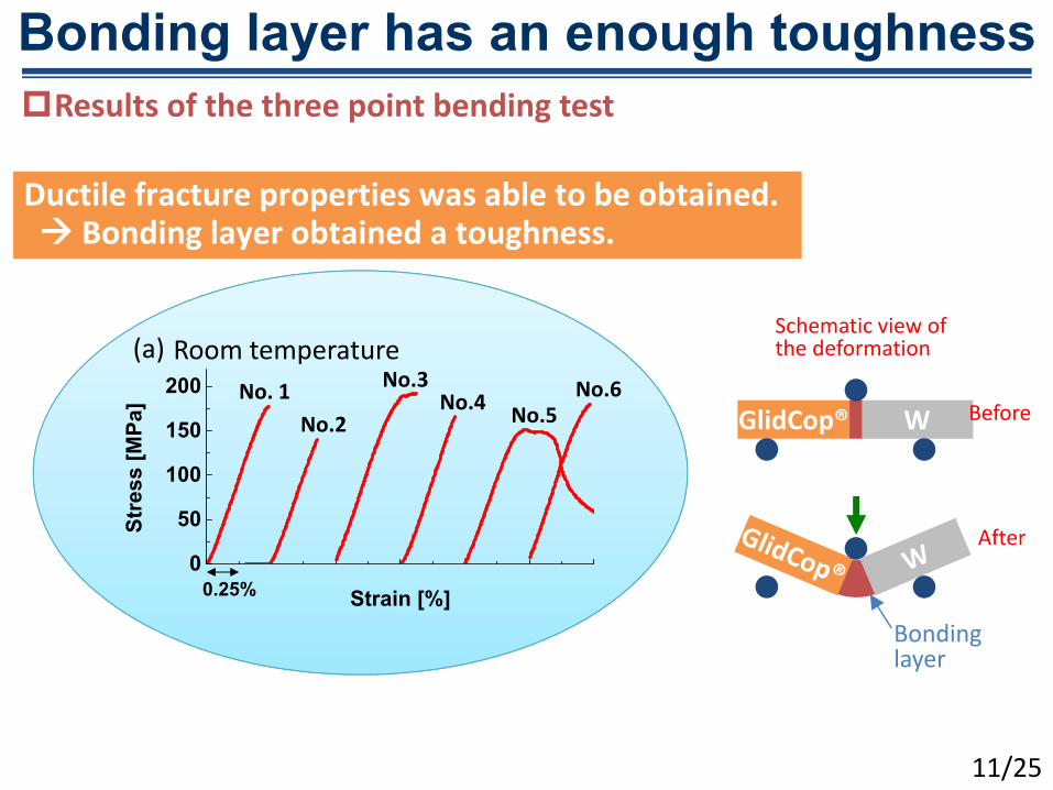
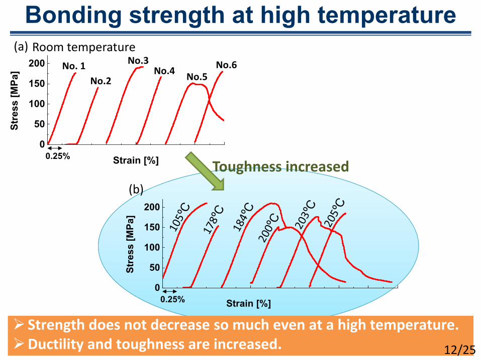
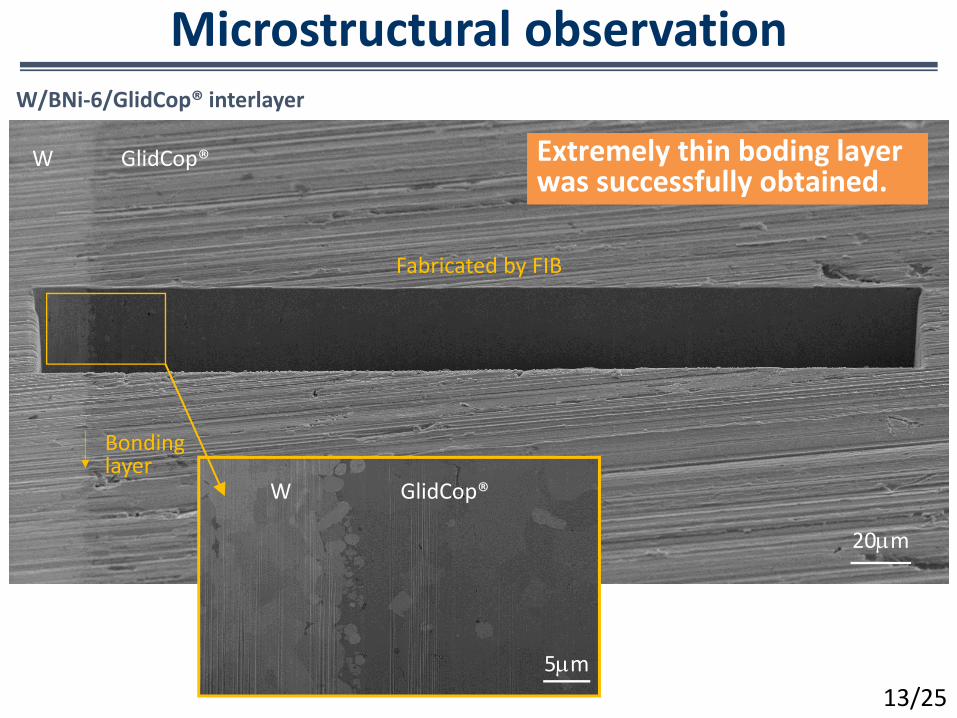
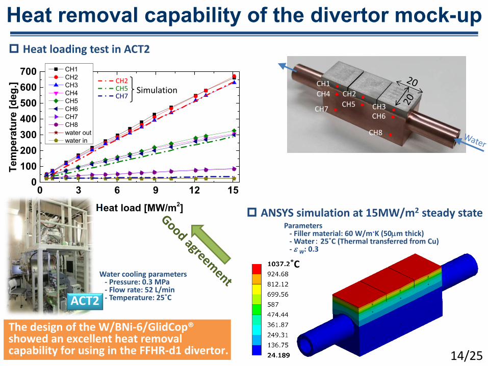
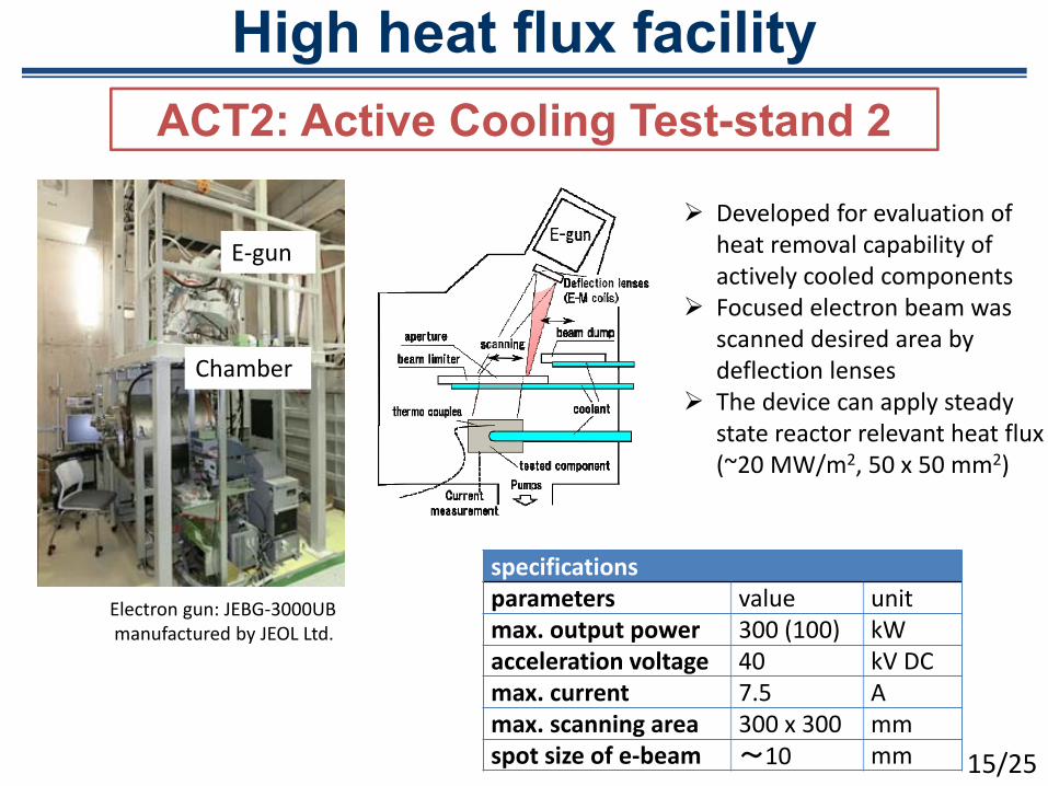
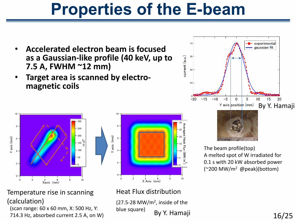
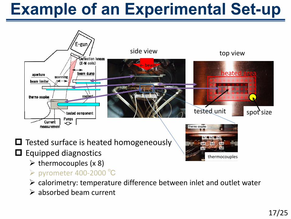
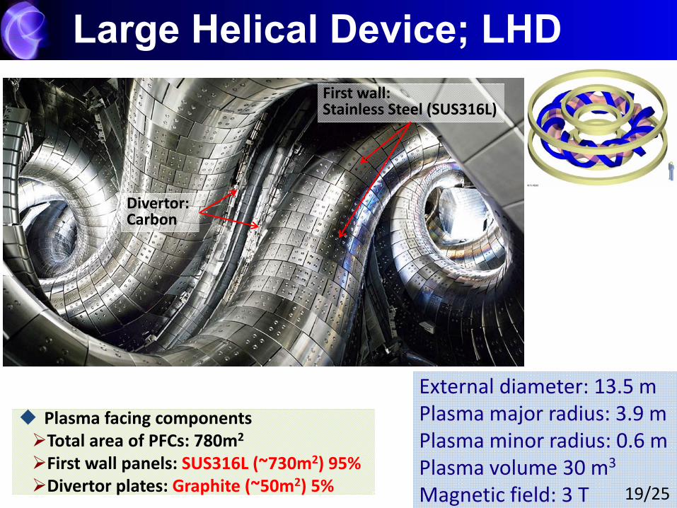
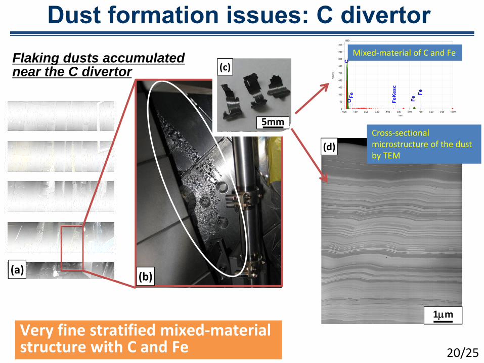
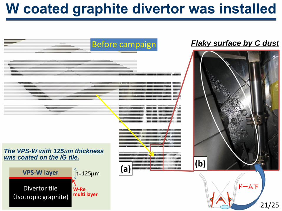
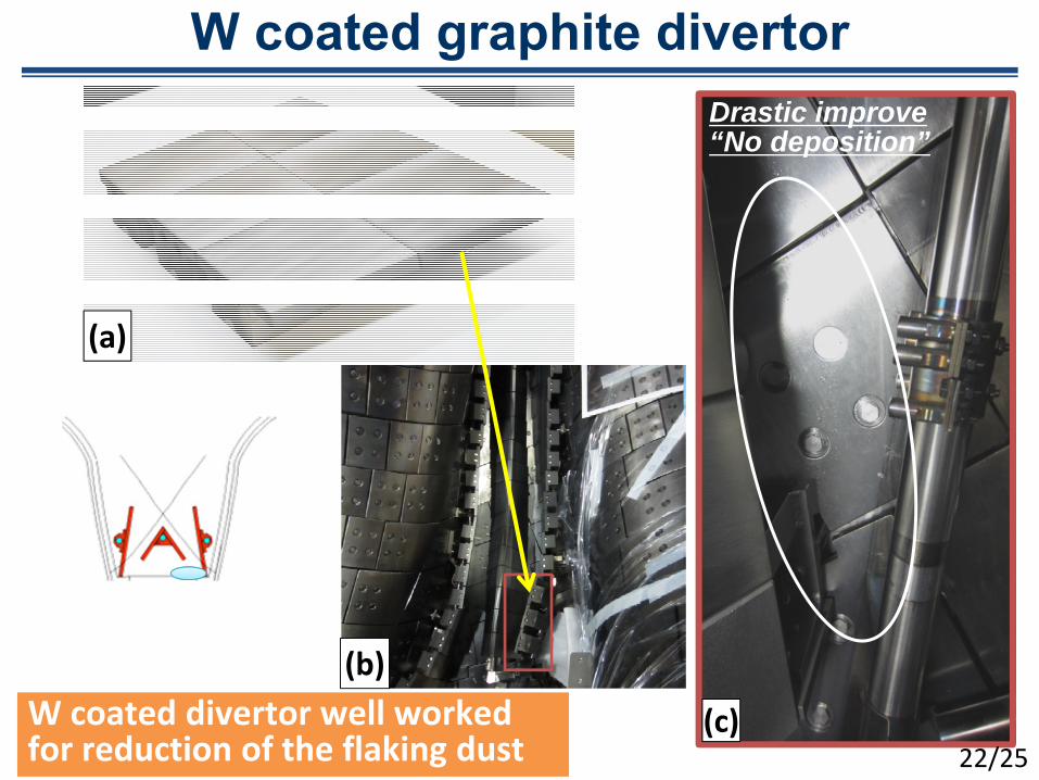
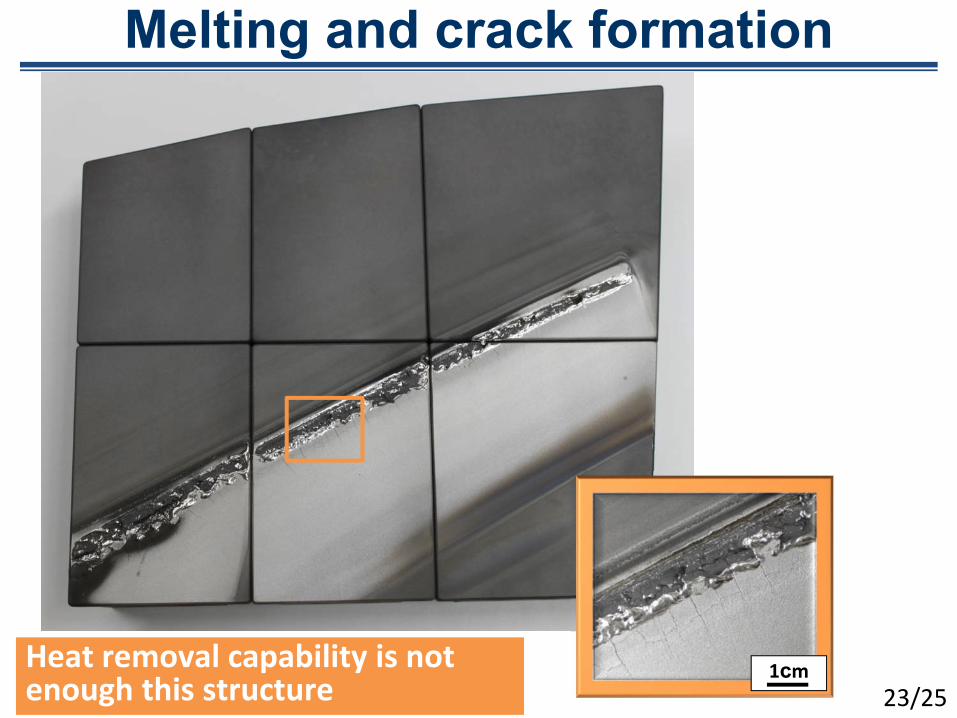
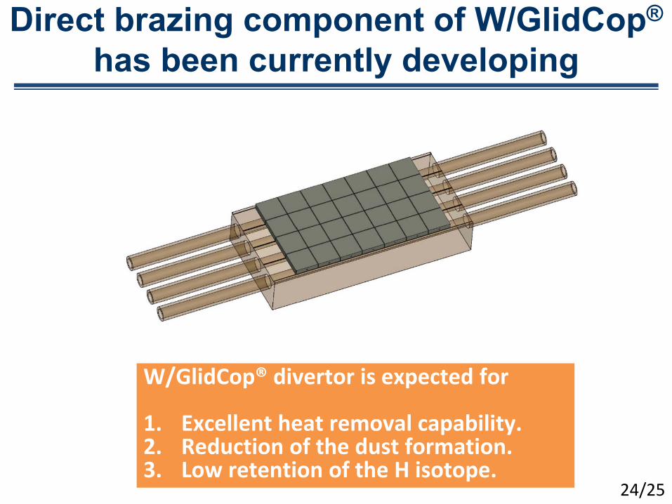