Embed Size (px)
Citation preview

115
Development of Software Package for Automated Scanning ofMultiple Surface Fuel Pellets Using Ultrasonic Imaging System
R.K. Jain1, A.A. Agashe1, T.S. Ananthakrishnan1, V.M. Joshi 1, K.L.N. Chinababu 2 and S. Muralidhar2
1 Electronics Division, 2 Metallic Fuels Division, Bhabha Atomic Research Centre, Mumbai, India - 400085
Email: [email protected]
AbstractElectronics Division, BARC in association with Metallic Fuels Division has developed an Ultrasonic Imaging System suitable for automatedinspection of metallic objects with multiple surface geometry. The electronics hardware and application software for this system has beendeveloped by Electronics Division and the design and development of the mechanical scanner was done by Metallic Fuels Division, BARC.The scanner has been successfully interfaced with the high-resolution ultrasonic imaging system (ULTIMA-200SP). A very significant featureof the ULTIMA-200SP system is the application software which performs various tasks of controlling various motors of scanner in additionto data acquisition, processing, analysis and information display. All these tasks must be carried out in a well synchronized manner for generatinghigh resolution B Scan and C Scan images of test objects. In order to meet stringent requirements of the user, ULTIMA software has beenextensively upgraded with new advanced features viz. Fast (coarse) and Slow (fine) scan for the speed optimization, Scanning of Cuboids andCylindrical objects in the user defined region of interest, 3D view of the C-Scan, gray level, dual or multiple color plot in B-Scan, C-Scanand 3D views. This paper describes the advanced Windows based application software package developed at ED, BARC and highlights its salientfeatures along with a brief description of the system hardware and relevant information.
2. Ultrasonic Imaging System
Main components of the ultrasonic imaging system are:
l Mechanical system for manipulating the probe-head toscan different objects
l Electrical system for drive-motors and their control forautomation
l Electronic system for ultrasonic generation and itsreception i.e. ULTIMA200SP
l Application software for integrating the mechanicalsystems and ultrasonic detection system to obtain thedesired ultrasonic images
2.1 The Mechanical system
The immersion ultrasonic testing is carried out in a tank750mm(L) X 500mm(W) X 300mm(D). The positioning of theprobe-head at a precise location is achieved through a five-axes movement. A sturdy bridge is used on which X, Y, Zmotors are mounted to locate the probe precisely alongCartesian co-ordinates. A Gimbal mechanism is used to anglethe probe θ degrees (+90º to -90º) with respect toperpendicular and swivel mechanism to rotate the probethrough Φ (360º) degrees. Proximity sensors and limitingswitches for all the axes movements have been provided ateach end of all the axes providing Cartesian and Polarmovements. Shaft position encoders serve as feedback
1. Introduction
Ultrasonics Imaging Techniques are now well establishedin Nondestructive Testing and Evaluation (NDT/E) ofmaterials. However, automated ultrasonic inspection ofobjects having multiple surface geometry is yet a challengingtask. This challenge is primarily due to the difficulty inmaintaining the probe normal or occasionally at a desiredangle to the surface of the object during ultrasonicinspection. The only viable option for automating theinspection is the immersion testing as it enables moving theprobe over the object while ensuring proper acousticcoupling. The scanner-manipulator for inspection of acomplex surface needs to have multiple-axes movement ofthe probe. A six axes precision mechanical scanner-manipulator has been fabricated by Nuclear Fuels Group,BARC. This scanner functions under the control of ULTIMA-200SP, an Ultrasonic Imaging System developed at ElectronicsDivision BARC. ULTIMA-200SP system consists of PCIcompatible cards for Ultrasonic Pulser/ Receiver and a 200MSPS Digitizer. The dedicated software developed for thissystem controls all tasks, including transducer positioningusing all the six axes, data acquisition, processing, analysisand information display that are necessary for generatinghigh resolution B & C Scan images of test object. This paperhighlights salient features of the application software alongwith a brief description of the system hardware and relevantinformation.
Proceedings of the National Seminar & Exhibitionon Non-Destructive Evaluation
NDE 2009, December 10-12, 2009

116 Jain et al. : Proceedings of the National Seminar & Exhibition on Non-Destructive Evaluation
motion sensors and Digital Read Outs (DRO’s) display theposition value for all axes.
2.2 Electrical system
All the drives, Cartesian and Polar, are motorized and usestepper-motors to move the probe-head. These arecontrollable using a PC through an appropriate motioncontroller interface card. The encoders and limit switcheshave been mounted at the extremities of all the axes to ensuresafety of the drive mechanism and the system. A pendantmode has also been provided for manual control andmovement of an individual axis. An emergency stop buttonthat over-rides all commands and brings the system to a halthas been provided on the pendant. All the drives, powersupplies and computer interfaces have been provided in astandard 19" electronic rack mount.
2.3 Electronic system
This consists of two parts. First one controls the motionof the drives to position the probe-head accurately. Themotors for all the axes are controlled through respectivecontroller and all the encoders are connected to Digital ReadOuts which display the co-ordinate location of each axis. Themotors move through motion controller cards which arecontrolled by the application software. The second unit isthe ULTIMA200SP whose hardware contains (i) PCI busbased pulser-receiver and (ii) a high speed digitizer card. ThePulser section generates the high voltage transmit pulseneeded for the excitation of the ultrasonic transducer and theRF echo signals sensed by the same transducer are routed
to the receiver section for amplification. The processed signalis fed to the digitizer card which is capable of samplingultrasonic echo signals (i.e. A-Scan waveforms) at a maximumsampling rate of 200 MSPS. The digitizer also provides triggersignal to the Pulser receiver card as per the selected PulseRepetition Frequency (PRF) ranging from 100Hz to 6KHz. Forimmersion scanning mode, first echo detection circuit, whichinitiates the acquisition on receiving the first echo (from topsurface of the specimen) has also been incorporated. Blockdiagram of this system is given in Fig.1.
2.4 Application Software
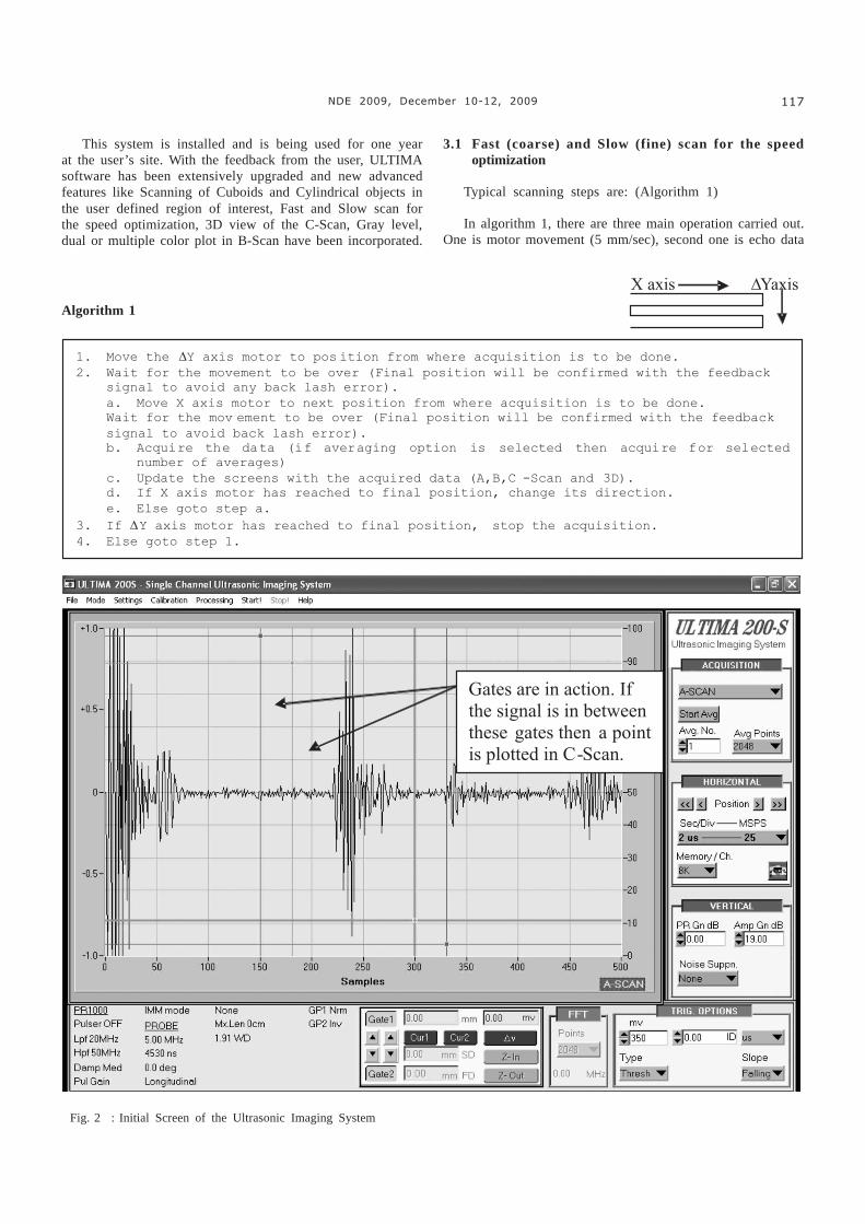
A powerful, Windows based software has been developedfor this system. This software enables the operator toposition the transducer suitably and select appropriate foracquiring optimum data for presenting the information in ameaningful way. Besides digitized A-Scan data, all theassociated parameters (such as sampling rate, pulser receiversettings, Amplifier gain etc.) are also stored. This is extremelyuseful for future referencing. Provision has been made todisplay the A-scan data & amplitude spectrum (FFT) of aselected portion (of the A-Scan) simultaneously. The echosignals can thus be analyzed in frequency domain online. Astatus window indicating the major parameters selected bythe user is always available on the screen. Another usefulfeature of the system is the provision of two independentuser selectable “gates”. User can define and locate each gateat the desired portion of the A-Scan and also specify thedesired amplitude threshold. If this threshold is crossedwithin the gate interval an audible beep is generated. Fig. 2shows a typical display of the software.
3. Software Features
Fig. 1 : Simplified block diagram of the Ultrasonic Imaging System
117NDE 2009, December 10-12, 2009
This system is installed and is being used for one yearat the user’s site. With the feedback from the user, ULTIMAsoftware has been extensively upgraded and new advancedfeatures like Scanning of Cuboids and Cylindrical objects inthe user defined region of interest, Fast and Slow scan forthe speed optimization, 3D view of the C-Scan, Gray level,dual or multiple color plot in B-Scan have been incorporated.
3.1 Fast (coarse) and Slow (fine) scan for the speedoptimization
Typical scanning steps are: (Algorithm 1)
In algorithm 1, there are three main operation carried out.One is motor movement (5 mm/sec), second one is echo data
Fig. 2 : Initial Screen of the Ultrasonic Imaging System
Algorithm 1

118 Jain et al. : Proceedings of the National Seminar & Exhibition on Non-Destructive Evaluation
acquisition with the sampling rate of 0.781 MSPS to 200MSPS (» 1280 to 5 nano seconds per sample) and third oneis GUI updation (»mSec). It can be seen that time is mainlytaken up by motor movement and GUI updation. In theexperimental setup we are using 25MSPS, 8K data and Noaverages for each channel. Dimension for the Test object isof the order of 200mm X 60mm and steps of 0.5 mm were usedin both directions. Total time required for this acquisition isapprox. 11 hrs. This scanning is termed as slow scan whichcan be adopted to obtain very fine details.
Another way of acquiring the data is by using followingalgorithm: (Algorithm 2)
In algorithm 2, motor movement and data acquisition isindependent but both operation is synchronized with thetimer interrupt. Our aim is to acquire data after every 0.5 mmin each direction and motor speed is 5 mm/sec so we requireacquisition after every 50msec. Total time required for thisacquisition is approx. 1 hrs giving an effective saving of timeof the order of 11. This scanning is termed as fast scan. Asshown in Fig. 3, display appears somewhat coarse, but theinformation content is more or less same as in the case ofslow scan.
3.2 Scanning of Cuboids and Cylindrical objects in the userdefined region of interest
Object may have different shapes viz. Cuboids orCylindrical. For Cuboidal object, we require to move themotor in X and ∆Y direction. For Cylindrical objects, thetaand DZ motors movement is required. Facility is provided inC-Scan panel to select which type of object is used forscanning. Accordingly, motors are initialized and moved forgetting B-Scan, C-Scan and 3-D image. Fig. 4 shows the C-Scan panel which provides facility for selecting differentgeometry.
3.3 3D view of the echo from Cylindrical Object
When we scan a cylindrical object, we want to visualizeechoes within cylindrical region. To incorporate this feature,we used 3D graph activeX control. One can see the objectfrom any angle. Zooming/Panning feature to see the defectin details is also provided. Fig. 4 also shows the C-Scanpanel with 3D view of cylindrical objects.
Fig. 4 : C-Scan panel for selecting different geometry, Motion, Gray or color display, Dual color display, Invert color display.
Fig. 3 : C-Scan with (a) Slow movement (b) Fast movement.(c) Experimental setup.

119NDE 2009, December 10-12, 2009
3.4 Gray level, dual or multiple color plot in B-Scan
In B-Scan view, facility is provided to see the ultrasonicimages either in gray scale or in dual color or in multiplecolors. The input signal (0-255) is mapped in gray level of 0-255 and is plotted in different gray intensity. For dual colordisplay, slider is provided which decides the threshold value(between 0-255), below which every pixel is displayed aswhite and above pixels are displayed as black color. Formultiple color display, color palette of 8 colors (with a windowof 32) is provided. All the pixels in the same window aredisplayed in same color. Fig. 4 shows this feature.
4. Conclusion
As shown in Fig. 3, there is no major change in theinformation display. It must be noted that no defect is missedin fast scan. Ability of detection of small defects and theirqualitative as well as quantitative characterization by fastscan gives immense confidence in this methodology of NDT.Other features like Scanning of Cuboids and Cylindricalobjects in the user defined region of interest, 3D view of theC-Scan, gray level, dual or multiple color plot in B-Scan, C-Scan and 3D views etc. are required for enhancing the user’sexperience, ease of operation and simplicity in understandingthe ultrasonic images. So we can say that Ultrasonics hasvery bright prospects in the detection of small flaws withreliability and repeatability in reduced scanning time.
Acknowledgments
The authors place on record their thanks to Shri P.K.Mukhopadhyay, Head, ED; Dr. G.J. Prasad, Head, MFD; Shri
G.P. Srivastava, Director EIG and Shri H.S. Kamath, DirectorNFG for their encouragement and support. This work involvesthe contribution of many colleagues in MFD and ED and theauthors would like to place on record their appreciation tothem. In particular the authors gratefully acknowledge theefforts and contributions made by Ms. Bhagyashree Saradein interfacing the motor drive with the PC and Shri HarishBadgujar for performing test trials.
References
1. Agashe A A, Badgujar H D, Chinnababu K L N, Jain R K, MittalR K, Muralidhar S, Randale G D, Sivakumar U, Tamhane A B,Ananthakrishnan TS, Joshi V M, Mahule K N and Prasad G J,An Ultrasonic Imaging System for Inspection of Objects with aMultiple Surface Geometry, Proc. Of the National Sminar onChallenges and Innovations in NDT (NDE 2009) held atLonavala, Mumbai (Dec. 1999)
2. Joshi V M, More S R, Patankar V H, Jyoti P, Kataria S K,ULTIMA 100+: An Ultrasonic imaging system for non destructivetesting of materials, BARC news letter No. 204, (Jan 2001)
3. Motiwala P D, Agashe A A, More S R, Joshi V M and KatariaS K, PCI bus based high speed digitizer for capture and analysisof Ultrasonic signals, Proc. Of the International conference andExhibition on Ultrasonics (ICEU 99) held at New Delhi (Dec.1999)
4. Joshi V M, More S R, Motiwala P D, Agashe A A, Lalwani S K,Ananthakrishnan T S and Kataria S K, Development of PCI busbased PC add-on cards for waveform analysis & video imagecapture, B.A.R.C. news letter No. 196, May 2000.