Embed Size (px)
Citation preview
Development of Self-Installing Deepwater Spar
Ashit Jadav
February 2017
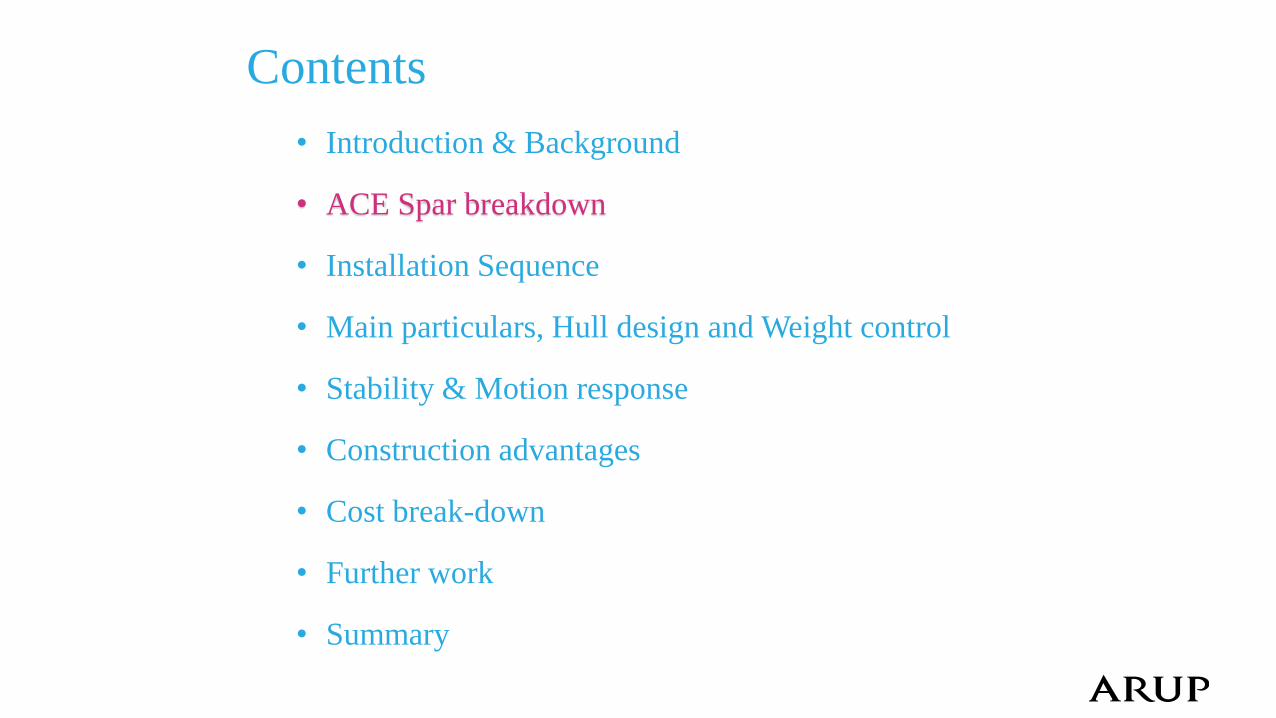
Contents
• Introduction & Background
• ACE Spar breakdown
• Installation Sequence
• Main particulars, Hull design and Weight control
• Stability & Motion response
• Construction advantages
• Cost break-down
• Further work
• Summary
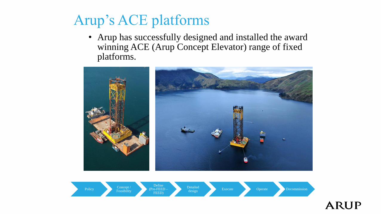
Arup’s ACE platforms • Arup has successfully designed and installed the award
winning ACE (Arup Concept Elevator) range of fixed platforms.
Policy Concept / Feasibility
Define (Pre-FEED –
FEED)
Detailed design
Execute Operate Decommission
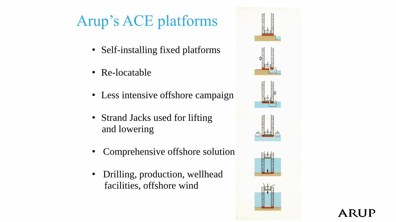
Arup’s ACE platforms
• Self-installing fixed platforms
• Re-locatable
• Less intensive offshore campaign
• Strand Jacks used for lifting
and lowering
• Comprehensive offshore solution
• Drilling, production, wellhead
facilities, offshore wind
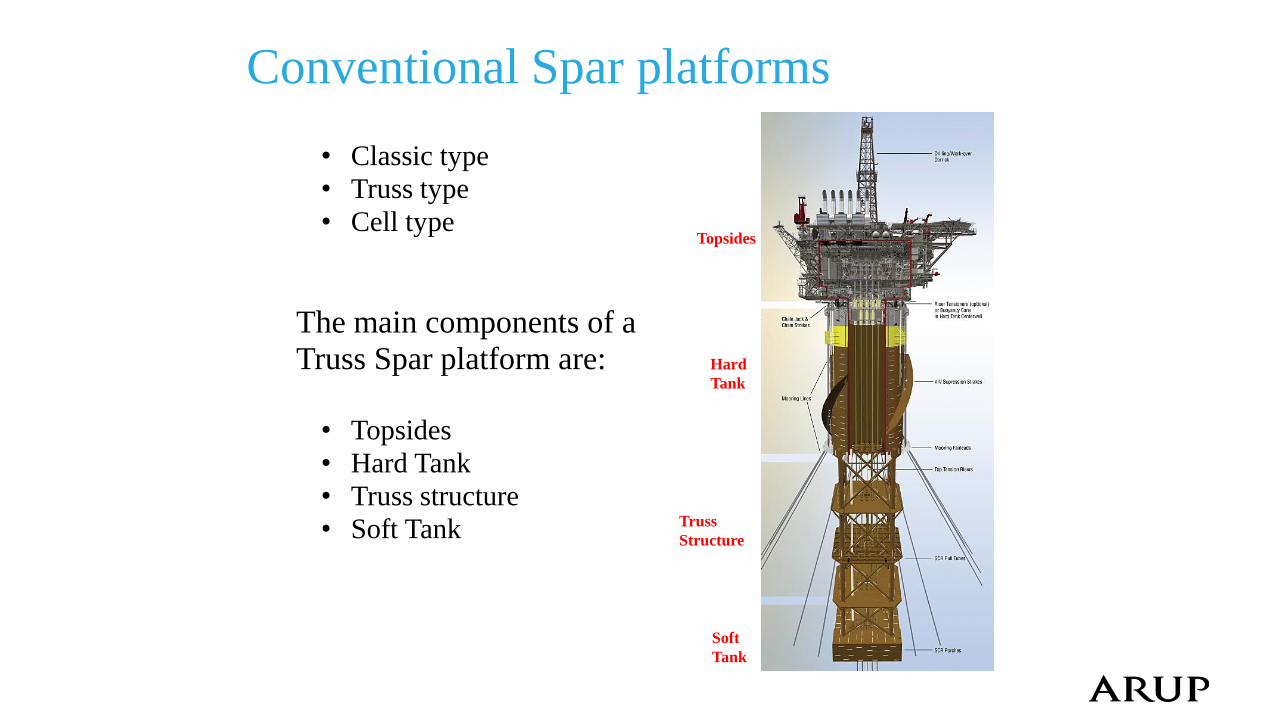
Conventional Spar platforms
• Classic type
• Truss type
• Cell type
The main components of a
Truss Spar platform are:
• Topsides
• Hard Tank
• Truss structure
• Soft Tank
Hard
Tank
Topsides
Soft
Tank
Truss
Structure
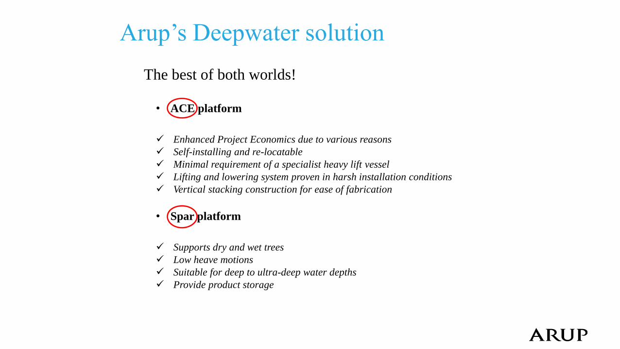
Arup’s Deepwater solution
The best of both worlds!
• ACE platform
Enhanced Project Economics due to various reasons
Self-installing and re-locatable
Minimal requirement of a specialist heavy lift vessel
Lifting and lowering system proven in harsh installation conditions
Vertical stacking construction for ease of fabrication
• Spar platform
Supports dry and wet trees
Low heave motions
Suitable for deep to ultra-deep water depths
Provide product storage
Contents
• Introduction & Background
• ACE Spar breakdown
• Installation Sequence
• Main particulars, Hull design and Weight control
• Stability & Motion response
• Construction advantages
• Cost break-down
• Further work
• Summary
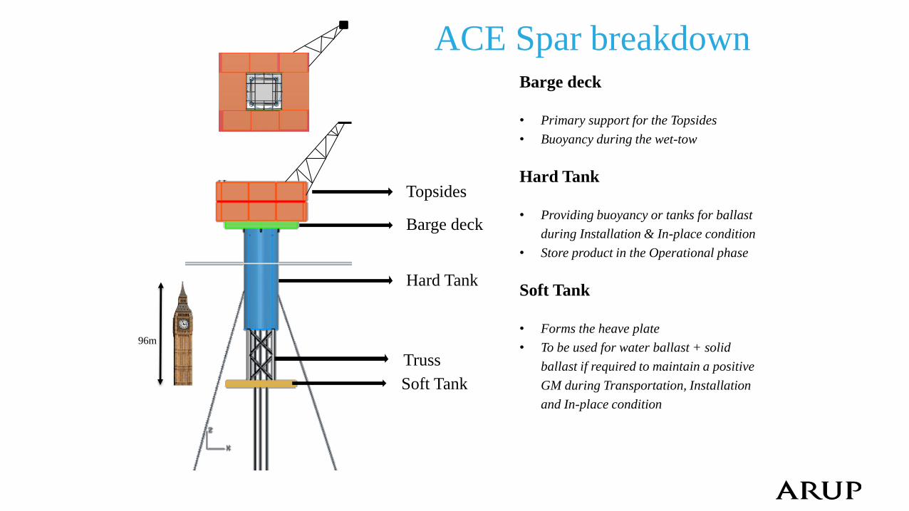
ACE Spar breakdown
Barge deck
Hard Tank
Truss
Soft Tank
Barge deck • Primary support for the Topsides
• Buoyancy during the wet-tow
Hard Tank
• Providing buoyancy or tanks for ballast
during Installation & In-place condition
• Store product in the Operational phase
Soft Tank
• Forms the heave plate
• To be used for water ballast + solid
ballast if required to maintain a positive
GM during Transportation, Installation
and In-place condition
Topsides
96m
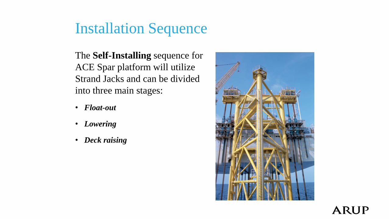
Installation Sequence
The Self-Installing sequence for
ACE Spar platform will utilize
Strand Jacks and can be divided
into three main stages: • Float-out
• Lowering
• Deck raising
Float-out
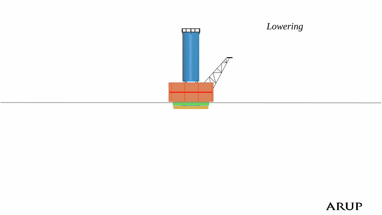
Lowering
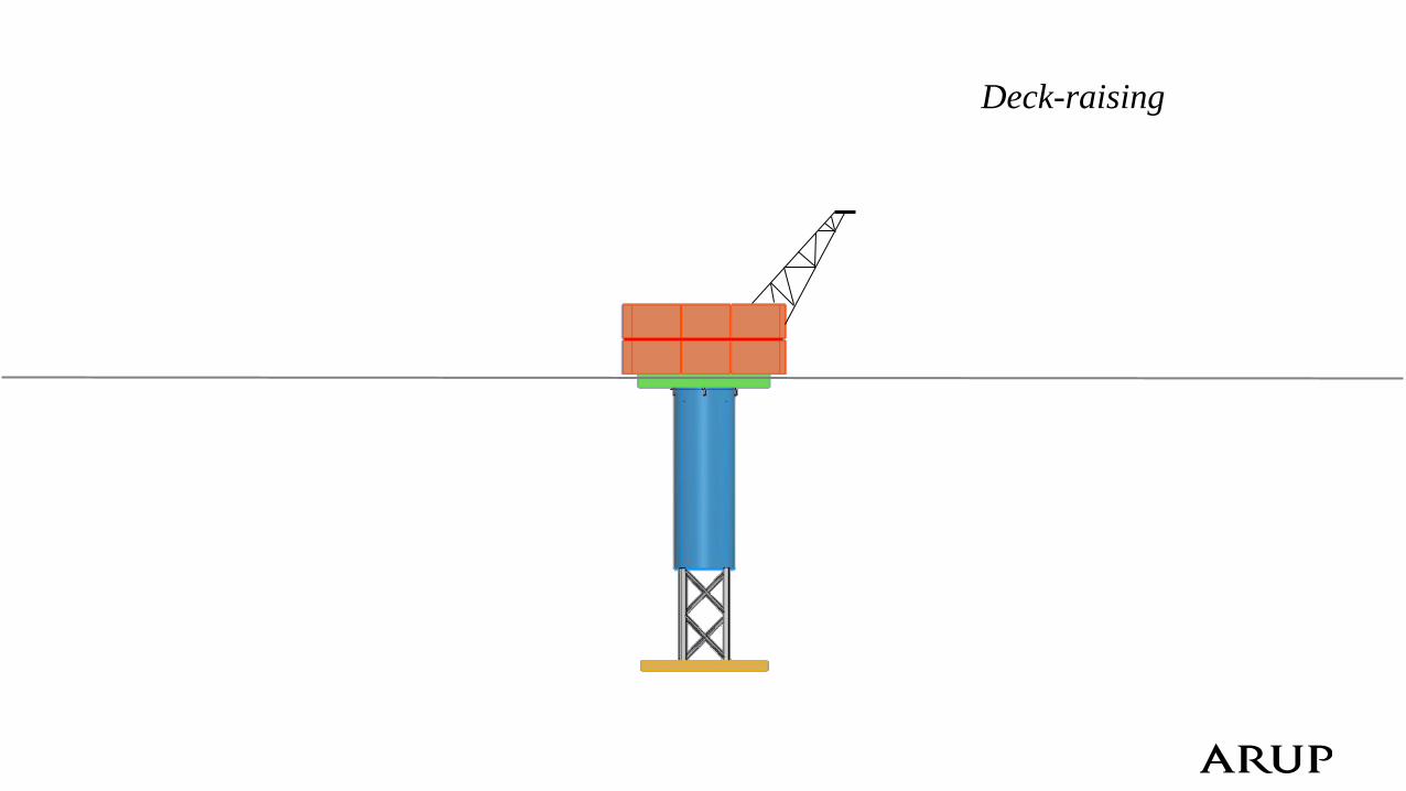
Deck-raising
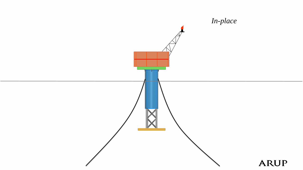
In-place
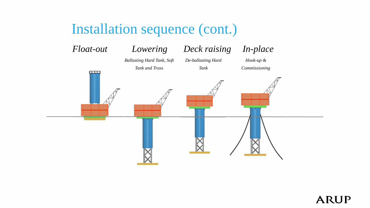
Installation sequence (cont.)
Float-out Lowering Deck raising In-place Ballasting Hard Tank, Soft
Tank and Truss
De-ballasting Hard
Tank
Hook-up &
Commissioning
Contents
• Introduction & Background
• ACE Spar breakdown
• Installation Sequence
• Main particulars, Hull design and Weight control
• Stability & Motion response
• Construction advantages
• Cost break-down
• Further work
• Summary
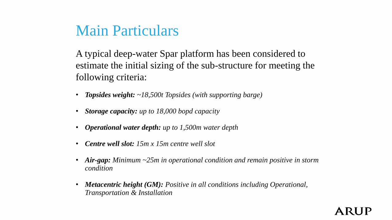
Main Particulars
A typical deep-water Spar platform has been considered to
estimate the initial sizing of the sub-structure for meeting the
following criteria: • Topsides weight: ~18,500t Topsides (with supporting barge)
• Storage capacity: up to 18,000 bopd capacity
• Operational water depth: up to 1,500m water depth
• Centre well slot: 15m x 15m centre well slot
• Air-gap: Minimum ~25m in operational condition and remain positive in storm
condition
• Metacentric height (GM): Positive in all conditions including Operational, Transportation & Installation
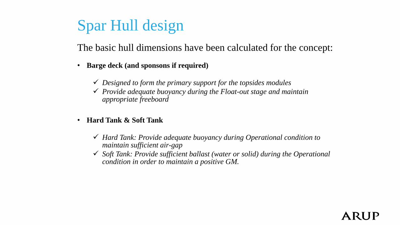
Spar Hull design
The basic hull dimensions have been calculated for the concept: • Barge deck (and sponsons if required)
Designed to form the primary support for the topsides modules
Provide adequate buoyancy during the Float-out stage and maintain appropriate freeboard
• Hard Tank & Soft Tank
Hard Tank: Provide adequate buoyancy during Operational condition to maintain sufficient air-gap
Soft Tank: Provide sufficient ballast (water or solid) during the Operational condition in order to maintain a positive GM.
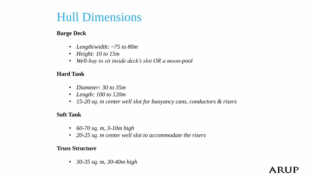
Hull Dimensions Barge Deck
• Length/width: ~75 to 80m
• Height: 10 to 15m
• Well-bay to sit inside deck’s slot OR a moon-pool Hard Tank
• Diameter: 30 to 35m
• Length: 100 to 120m
• 15-20 sq. m center well slot for buoyancy cans, conductors & risers
Soft Tank
• 60-70 sq. m, 3-10m high
• 20-25 sq. m center well slot to accommodate the risers
Truss Structure
• 30-35 sq. m, 30-40m high
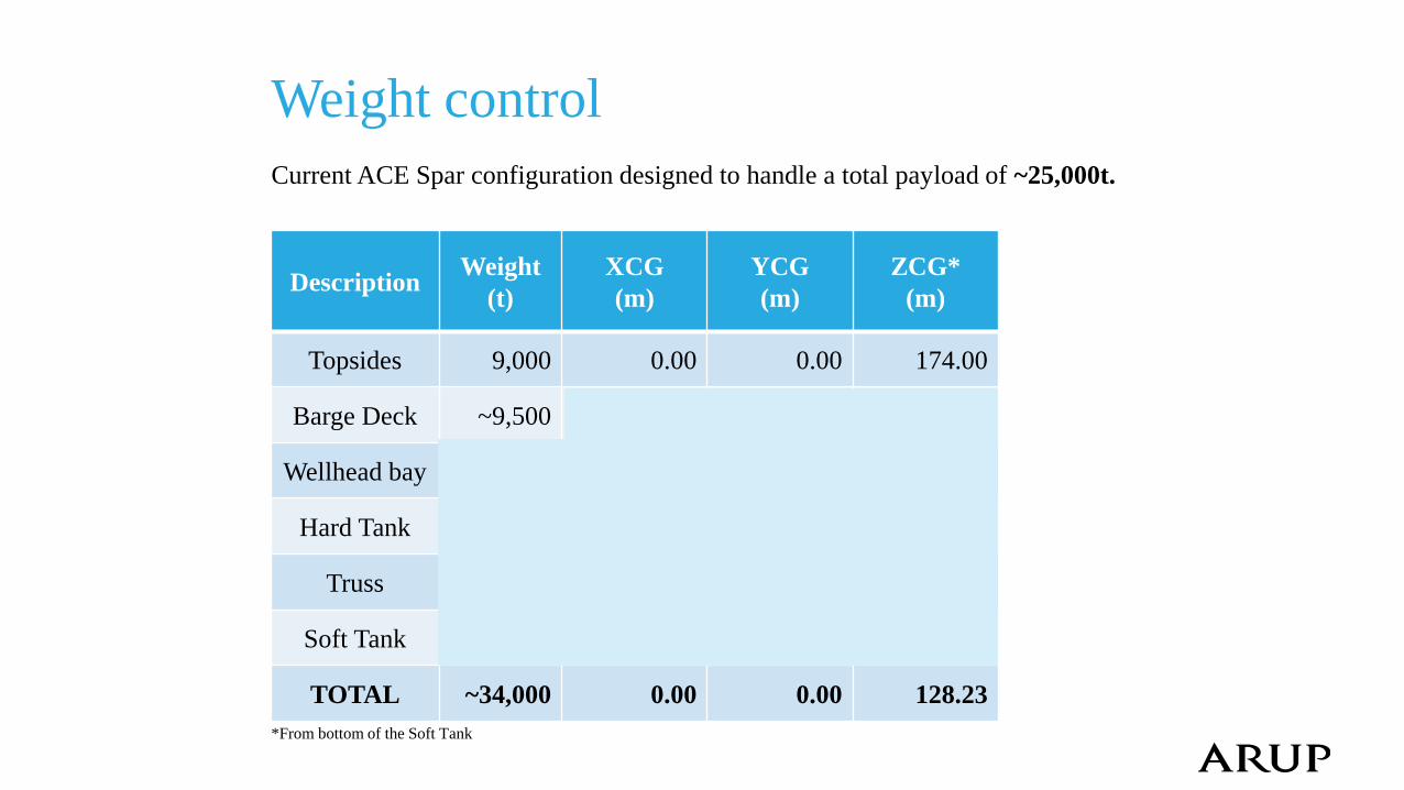
Weight control
Current ACE Spar configuration designed to handle a total payload of ~25,000t.
*From bottom of the Soft Tank
Description Weight
(t)
XCG
(m)
YCG
(m)
ZCG*
(m)
Topsides 9,000 0.00 0.00 174.00
Barge Deck ~9,500
Wellhead bay
Hard Tank
Truss
Soft Tank
TOTAL ~34,000 0.00 0.00 128.23
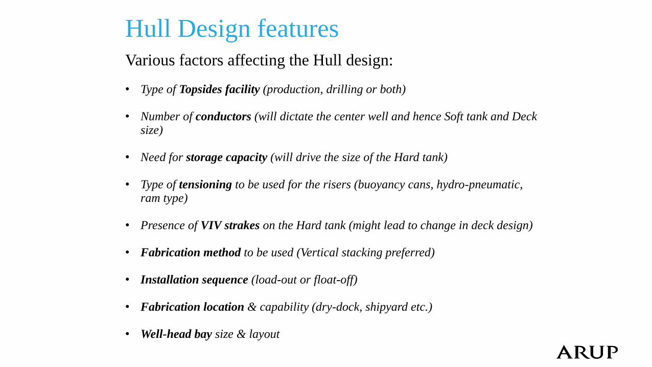
Hull Design features Various factors affecting the Hull design: • Type of Topsides facility (production, drilling or both)
• Number of conductors (will dictate the center well and hence Soft tank and Deck
size)
• Need for storage capacity (will drive the size of the Hard tank)
• Type of tensioning to be used for the risers (buoyancy cans, hydro-pneumatic, ram type)
• Presence of VIV strakes on the Hard tank (might lead to change in deck design)
• Fabrication method to be used (Vertical stacking preferred)
• Installation sequence (load-out or float-off)
• Fabrication location & capability (dry-dock, shipyard etc.)
• Well-head bay size & layout
Contents
• Introduction & Background
• ACE Spar breakdown
• Installation Sequence
• Main particulars, Hull design and Weight control
• Stability & Motion response
• Construction advantages
• Cost break-down
• Further work
• Summary
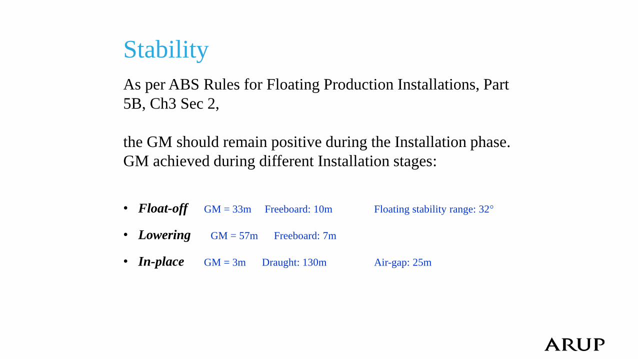
Stability
As per ABS Rules for Floating Production Installations, Part
5B, Ch3 Sec 2,
the GM should remain positive during the Installation phase.
GM achieved during different Installation stages:
• Float-off GM = 33m Freeboard: 10m Floating stability range: 32°
• Lowering GM = 57m Freeboard: 7m
• In-place GM = 3m Draught: 130m Air-gap: 25m
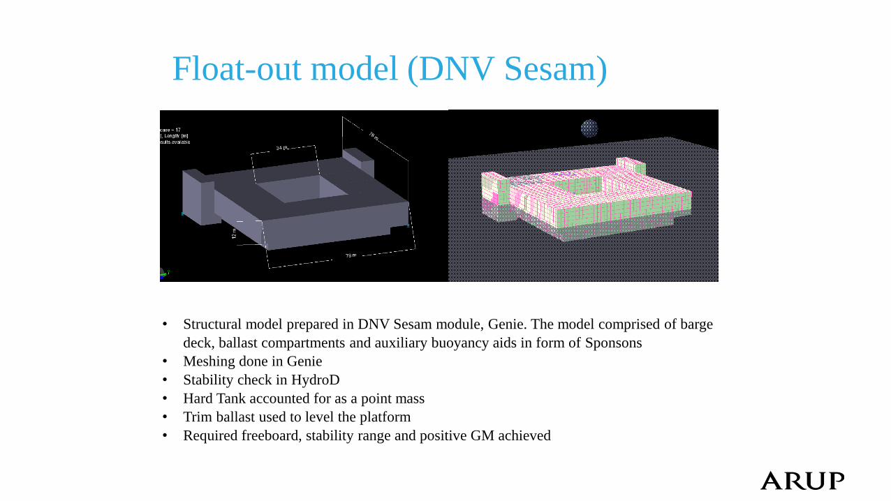
Float-out model (DNV Sesam)
• Structural model prepared in DNV Sesam module, Genie. The model comprised of barge
deck, ballast compartments and auxiliary buoyancy aids in form of Sponsons
• Meshing done in Genie
• Stability check in HydroD
• Hard Tank accounted for as a point mass
• Trim ballast used to level the platform
• Required freeboard, stability range and positive GM achieved
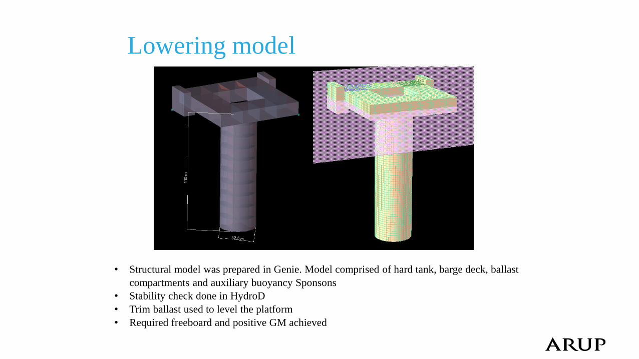
Lowering model
• Structural model was prepared in Genie. Model comprised of hard tank, barge deck, ballast
compartments and auxiliary buoyancy Sponsons
• Stability check done in HydroD
• Trim ballast used to level the platform
• Required freeboard and positive GM achieved
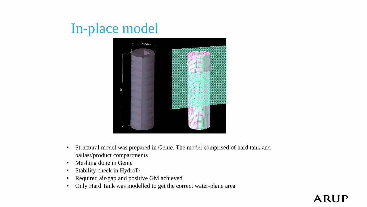
In-place model
• Structural model was prepared in Genie. The model comprised of hard tank and
ballast/product compartments
• Meshing done in Genie
• Stability check in HydroD
• Required air-gap and positive GM achieved
• Only Hard Tank was modelled to get the correct water-plane area
Motion Response
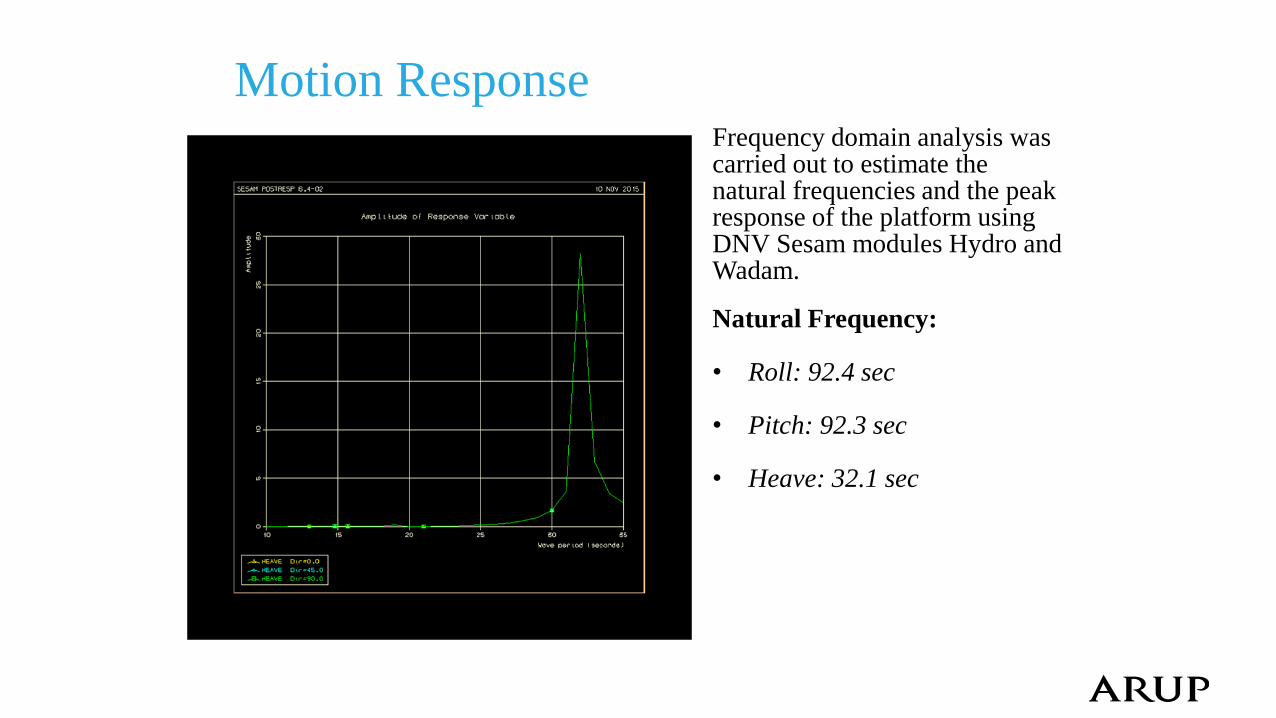
Natural Frequency: • Roll: 92.4 sec • Pitch: 92.3 sec • Heave: 32.1 sec
Frequency domain analysis was carried out to estimate the natural frequencies and the peak response of the platform using DNV Sesam modules Hydro and Wadam.
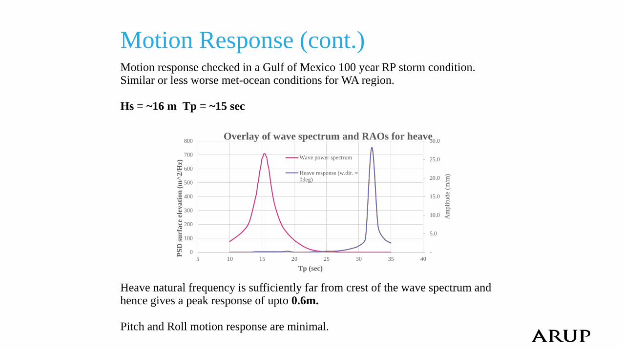
Motion Response (cont.)
Heave natural frequency is sufficiently far from crest of the wave spectrum and hence gives a peak response of upto 0.6m. Pitch and Roll motion response are minimal.
-
5.0
10.0
15.0
20.0
25.0
30.0
0
100
200
300
400
500
600
700
800
5 10 15 20 25 30 35 40
Am
pli
tud
e (m
/m)
PS
D s
urf
ace
ele
va
tio
n (
m^
2/H
z)
Tp (sec)
Overlay of wave spectrum and RAOs for heave
Wave power spectrum
Heave response (w.dir. =
0deg)
Motion response checked in a Gulf of Mexico 100 year RP storm condition. Similar or less worse met-ocean conditions for WA region. Hs = ~16 m Tp = ~15 sec
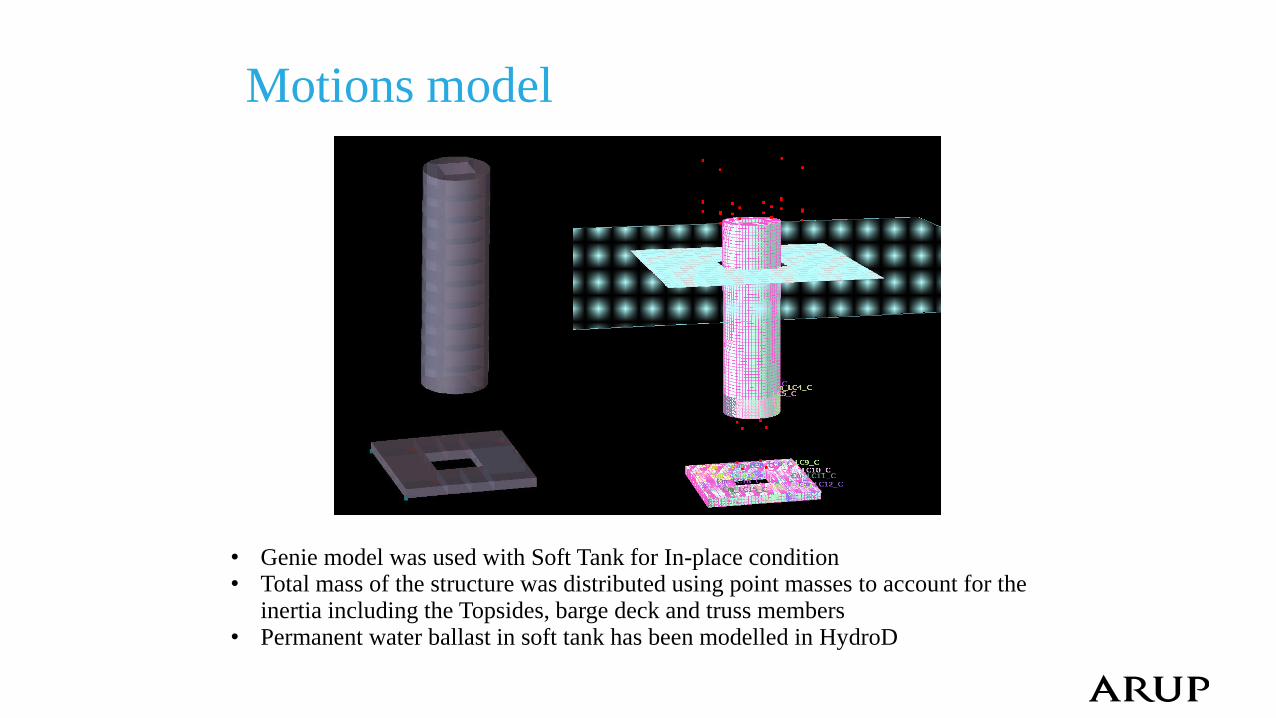
Motions model
• Genie model was used with Soft Tank for In-place condition • Total mass of the structure was distributed using point masses to account for the
inertia including the Topsides, barge deck and truss members • Permanent water ballast in soft tank has been modelled in HydroD
Contents
• Introduction & Background
• ACE Spar breakdown
• Installation Sequence
• Main particulars, Hull design and Weight control
• Stability & Motion response
• Construction advantages
• Cost break-down
• Further work
• Summary
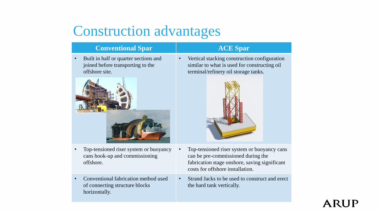
Construction advantages Conventional Spar ACE Spar
• Built in half or quarter sections and
joined before transporting to the
offshore site.
• Vertical stacking construction configuration
similar to what is used for constructing oil
terminal/refinery oil storage tanks.
• Top-tensioned riser system or buoyancy
cans hook-up and commissioning
offshore.
• Top-tensioned riser system or buoyancy cans
can be pre-commissioned during the
fabrication stage onshore, saving significant
costs for offshore installation.
• Conventional fabrication method used
of connecting structure blocks
horizontally.
• Strand Jacks to be used to construct and erect
the hard tank vertically.
Contents
• Introduction & Background
• ACE Spar breakdown
• Installation Sequence
• Main particulars, Hull design and Weight control
• Stability & Motion response
• Construction advantages
• Cost break-down
• Further work
• Summary
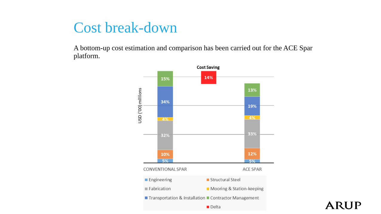
Cost break-down
A bottom-up cost estimation and comparison has been carried out for the ACE Spar platform.
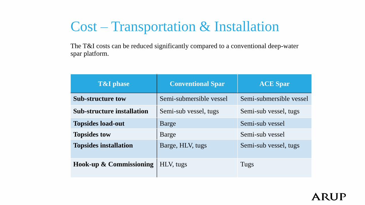
Cost – Transportation & Installation
The T&I costs can be reduced significantly compared to a conventional deep-water spar platform.
T&I phase Conventional Spar ACE Spar
Sub-structure tow Semi-submersible vessel Semi-submersible vessel
Sub-structure installation Semi-sub vessel, tugs Semi-sub vessel, tugs
Topsides load-out Barge Semi-sub vessel
Topsides tow Barge Semi-sub vessel
Topsides installation Barge, HLV, tugs Semi-sub vessel, tugs
Hook-up & Commissioning HLV, tugs Tugs
Contents
• Introduction & Background
• ACE Spar breakdown
• Installation Sequence
• Main particulars, Hull design and Weight control
• Stability & Motion response
• Construction advantages
• Cost break-down
• Further work
• Summary
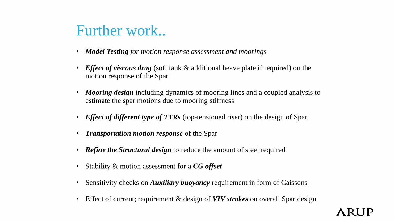
Further work..
• Model Testing for motion response assessment and moorings
• Effect of viscous drag (soft tank & additional heave plate if required) on the motion response of the Spar
• Mooring design including dynamics of mooring lines and a coupled analysis to estimate the spar motions due to mooring stiffness
• Effect of different type of TTRs (top-tensioned riser) on the design of Spar
• Transportation motion response of the Spar
• Refine the Structural design to reduce the amount of steel required
• Stability & motion assessment for a CG offset
• Sensitivity checks on Auxiliary buoyancy requirement in form of Caissons
• Effect of current; requirement & design of VIV strakes on overall Spar design
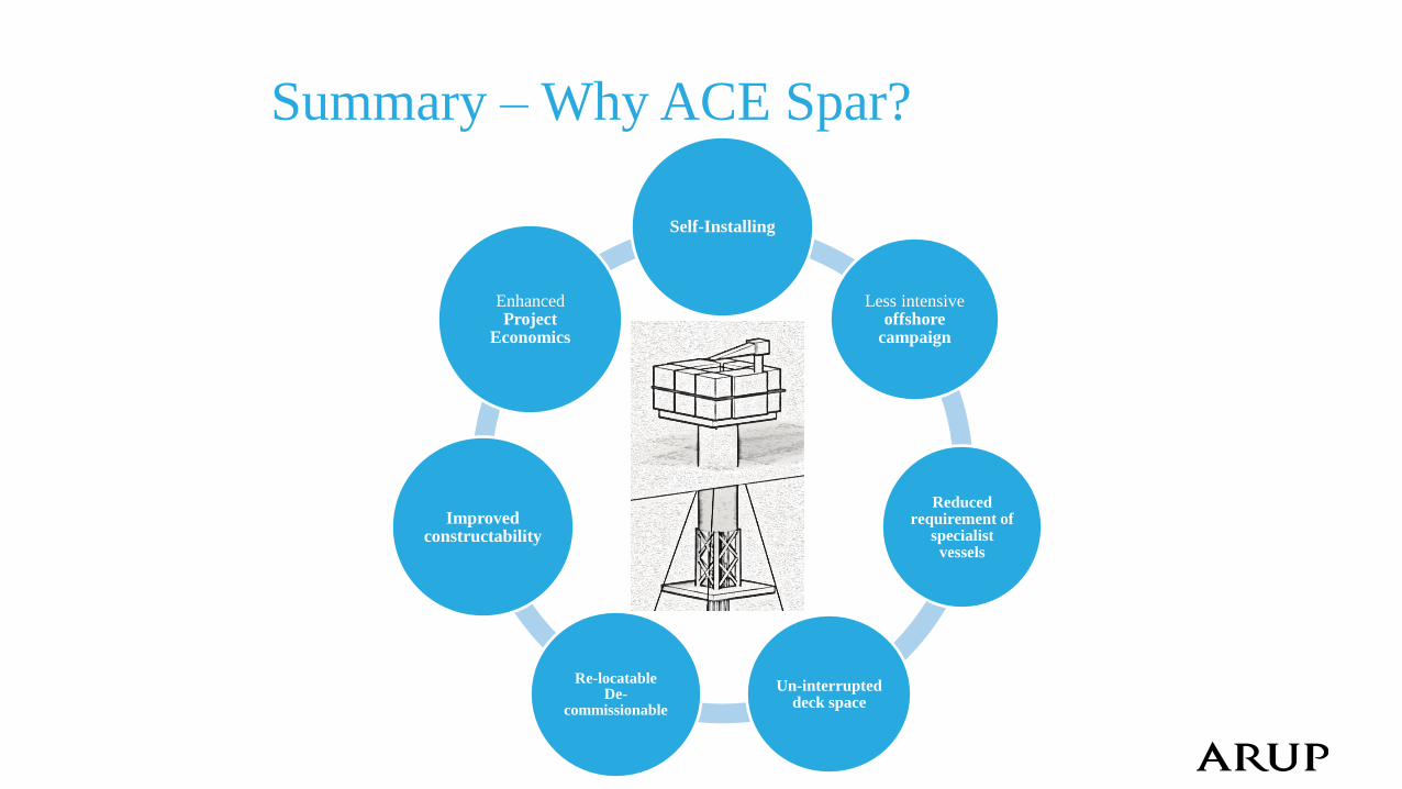
Summary – Why ACE Spar?
Self-Installing
Less intensive offshore
campaign
Reduced requirement of
specialist vessels
Un-interrupted deck space
Re-locatable De-
commissionable
Improved constructability
Enhanced Project
Economics
Thank you
Questions?