Embed Size (px)
Citation preview
Development of RF Undulator-Based Insertion Devices for Storage Rings and Free Electron lasers
Sami Tantawi, Jeff Neilson, Robert Hettel, Gordon Bowden

Outline
• Background• Motivation• Approach• Work Plan
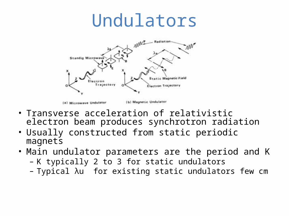
Undulators
• Transverse acceleration of relativistic electron beam produces synchrotron radiation
• Usually constructed from static periodic magnets• Main undulator parameters are the period and K
– K typically 2 to 3 for static undulators– Typical λu for existing static undulators few cm
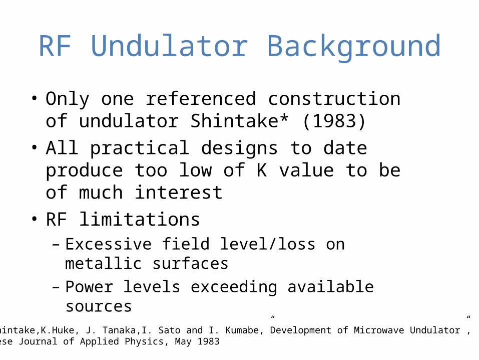
RF Undulator Background
• Only one referenced construction of undulator Shintake* (1983)
• All practical designs to date produce too low of K value to be of much interest
• RF limitations– Excessive field level/loss on metallic
surfaces– Power levels exceeding available
sources*T. Shintake,K.Huke, J. Tanaka,I. Sato and I. Kumabe,”Development of Microwave Undulator”,Japanese Journal of Applied Physics, May 1983
Why RF Undulator?
• Many desirable features– Fast dynamic control of
• Polarization• Wavelength• K
– Large aperture (cm vs mm for static undulator)
– No issue with permanent magnet damage by radiation
– Economic considerations– Potential use as LCLS “After Burner”– Dynamic undulator for storage ring
04/18/23 Page 6
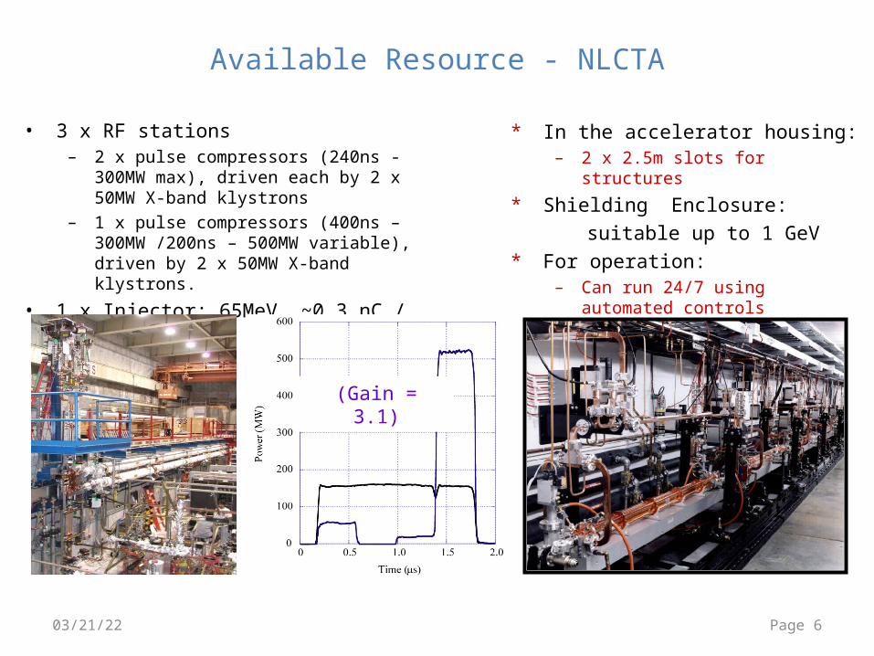
Available Resource - NLCTA
• 3 x RF stations– 2 x pulse compressors (240ns -
300MW max), driven each by 2 x 50MW X-band klystrons
– 1 x pulse compressors (400ns – 300MW /200ns – 500MW variable), driven by 2 x 50MW X-band klystrons.
• 1 x Injector: 65MeV, ~0.3 nC / bunch
* In the accelerator housing:– 2 x 2.5m slots for structures
* Shielding Enclosure: suitable up to 1 GeV
* For operation:– Can run 24/7 using automated
controls
(Gain = 3.1)
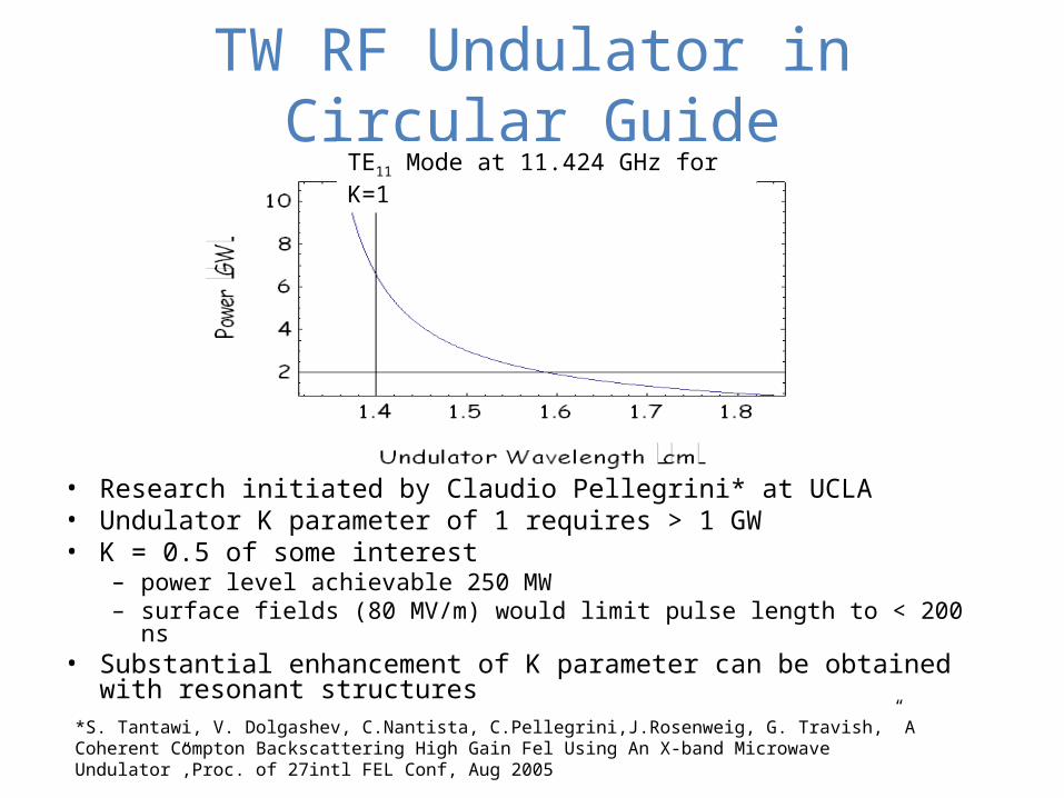
TW RF Undulator in Circular Guide
• Research initiated by Claudio Pellegrini* at UCLA • Undulator K parameter of 1 requires > 1 GW• K = 0.5 of some interest
– power level achievable 250 MW – surface fields (80 MV/m) would limit pulse length to < 200 ns
• Substantial enhancement of K parameter can be obtained with resonant structures
TE11 Mode at 11.424 GHz for K=1
*S. Tantawi, V. Dolgashev, C.Nantista, C.Pellegrini,J.Rosenweig, G. Travish,” A Coherent Compton Backscattering High Gain Fel Using An X-band Microwave Undulator”,Proc. of 27intl FEL Conf, Aug 2005
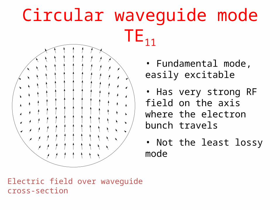
Circular waveguide mode TE11
• Fundamental mode, easily excitable
• Has very strong RF field on the axis where the electron bunch travels
• Not the least lossy mode
Electric field over waveguide cross-section
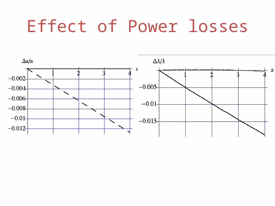
Effect of Power losses
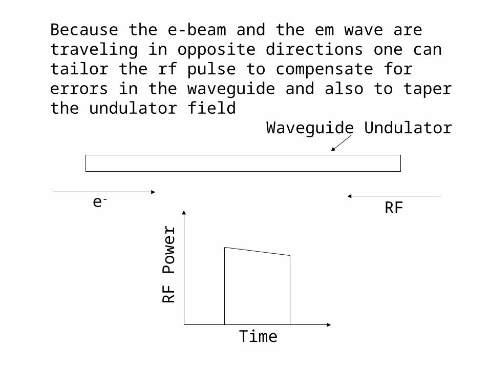
Because the e-beam and the em wave are traveling in opposite directions one can tailor the rf pulse to compensate for errors in the waveguide and also to taper the undulator field
e-RF
Time
RF
Pow
er
Waveguide Undulator
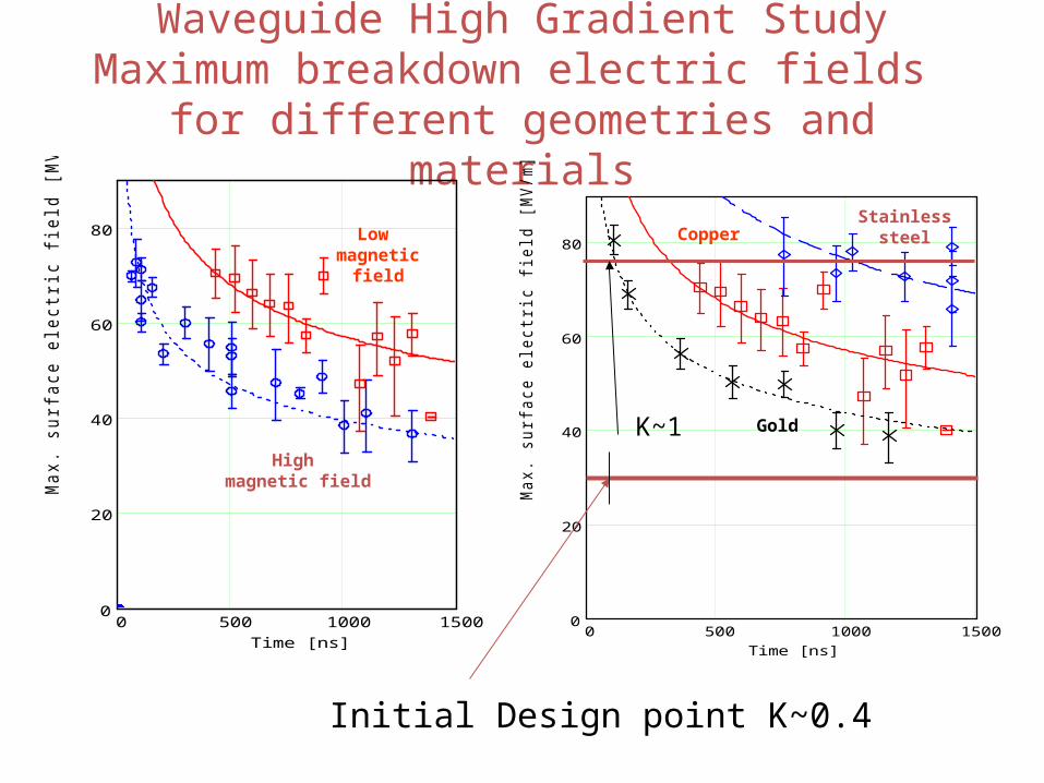
Waveguide High Gradient StudyMaximum breakdown electric fields
for different geometries and materialsM2sort
0 500 1000 15000
20
40
60
80
Time [ns]
Max
. su
rfac
e el
ectr
ic f
ield
[M
V/m
]
0 500 1000 15000
20
40
60
80
Time [ns]
Max
. su
rfac
e el
ectr
ic f
ield
[M
V/m
]
Low magnetic field
High magnetic field
Gold
CopperStainless
steel
Initial Design point K~0.4
K~1
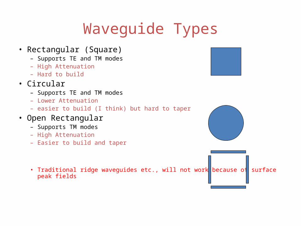
Waveguide Types• Rectangular (Square)
– Supports TE and TM modes– High Attenuation– Hard to build
• Circular – Supports TE and TM modes– Lower Attenuation– easier to build (I think) but hard to taper
• Open Rectangular– Supports TM modes– High Attenuation– Easier to build and taper
• Traditional ridge waveguides etc., will not work because of surface peak fields
10 5 0 5 1010
5
0
5
10
1 0.5 0 0.5 1
0.6
0.4
0.2
0
0.2
0.4
0.6
1.5 1 0.5 0 0.5 1 1.50
1
2
3
4
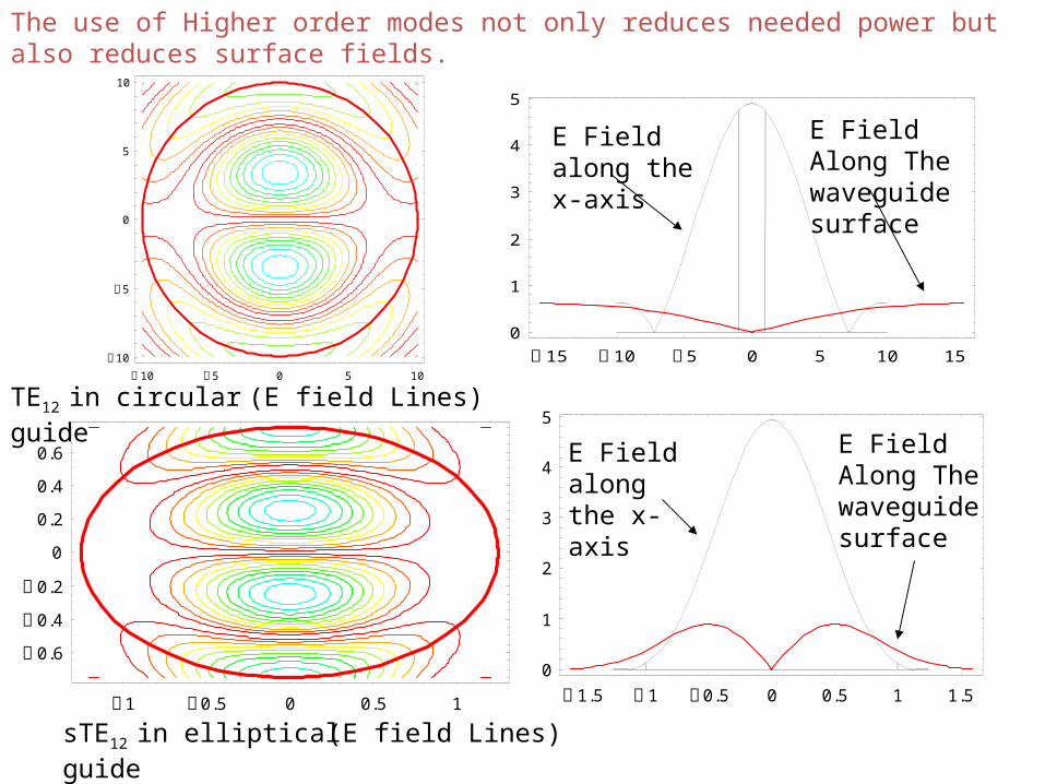
5TE12 in circular guide (E field Lines)
15 10 5 0 5 10 150
1
2
3
4
5
E Field along the x-axis
E Field Along The waveguide surface
E Field along the x-axis
E Field Along The waveguide surface
sTE12 in elliptical guide (E field Lines)
The use of Higher order modes not only reduces needed power but also reduces surface fields.
1 0.5 0 0.5 1
0.60.40.2
00.20.40.6
1.5 1 0.5 0 0.5 1 1.50
1
2
3
4
25 50 75 100 125 150 175
0.2
0.4
0.6
0.8
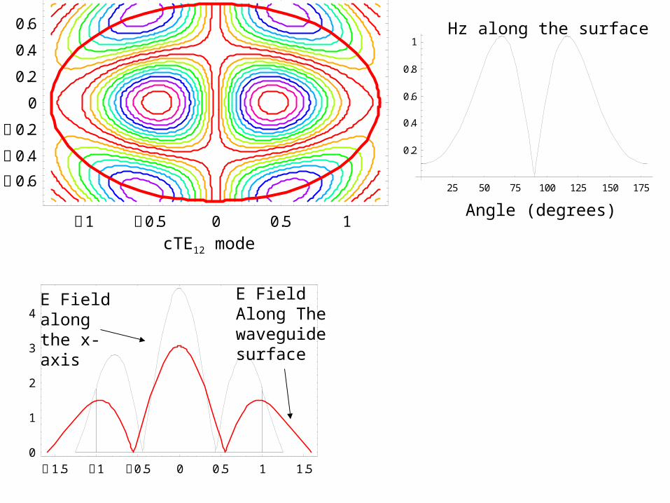
1Hz along the surface
cTE12 mode
E Field along the x-axis
E Field Along The waveguide surface
Angle (degrees)
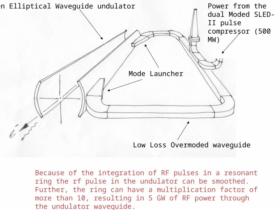
Power from the dual Moded SLED-II pulse compressor (500 MW)
Open Elliptical Waveguide undulator
Low Loss Overmoded waveguide
Mode Launcher
Because of the integration of RF pulses in a resonant ring the rf pulse in the undulator can be smoothed. Further, the ring can have a multiplication factor of more than 10, resulting in 5 GW of RF power through the undulator waveguide.
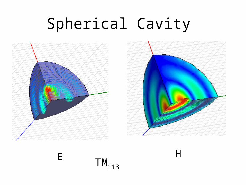
Spherical Cavity
E HTM113
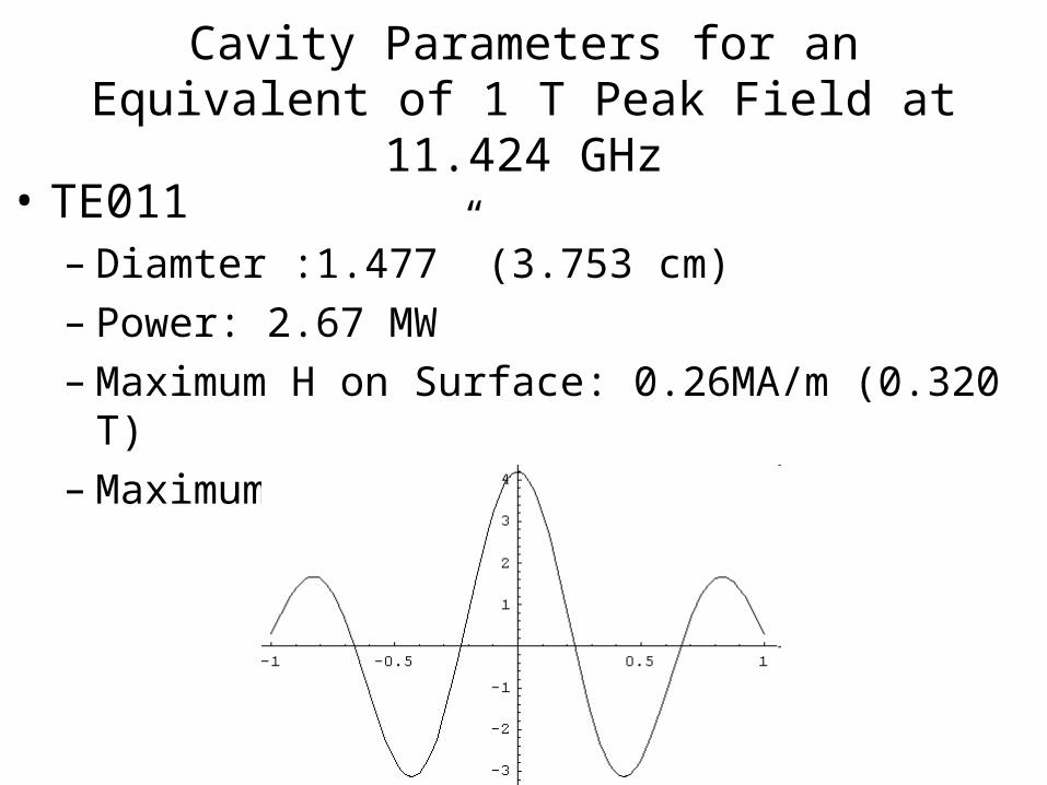
Cavity Parameters for an Equivalent of 1 T Peak Field at 11.424 GHz
• TE011– Diamter :1.477” (3.753 cm)– Power: 2.67 MW– Maximum H on Surface: 0.26MA/m (0.320 T)– Maximum E on surface: 0 MV/m
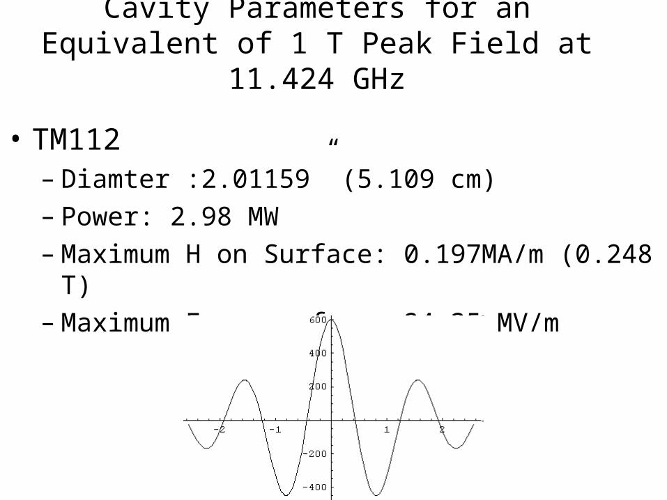
Cavity Parameters for an Equivalent of 1 T Peak Field at 11.424 GHz
• TM112– Diamter :2.01159” (5.109 cm)– Power: 2.98 MW– Maximum H on Surface: 0.197MA/m (0.248 T)– Maximum E on surface: 24.35 MV/m
The Perl String Undulator
• Even with optimized diamter and operating frequency, For a waveguide resonators, the end is a problem. Its losses dominates
• Also We need to reduce the average power for a near CW undulator operation. (However, it could be done as superconducting device)
• Spherical cavities offer about 35% increase in Q factor over circular cylindrical ones.
• Also highly overmoded spherical cavities can have a very low surface fields in comparison with the center field.
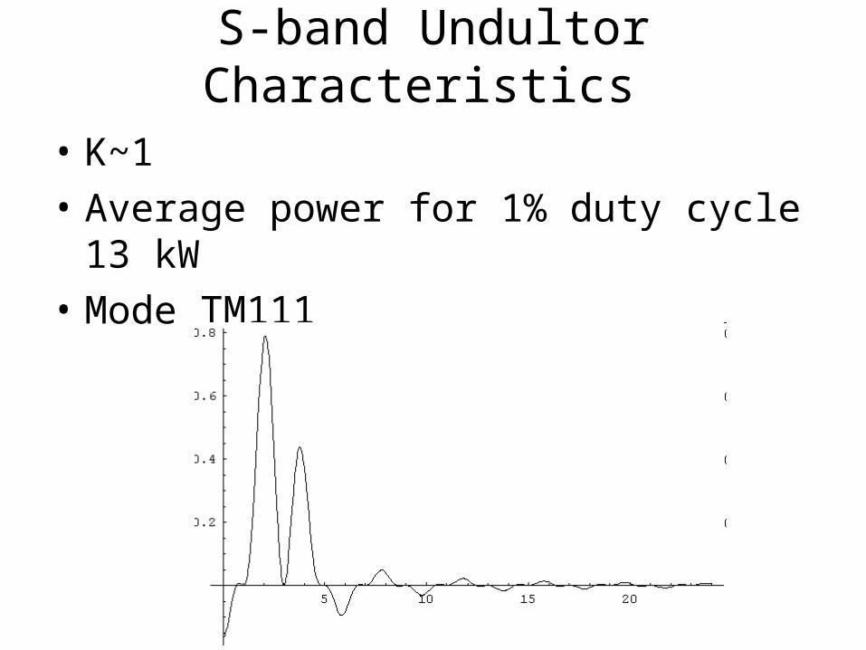
S-band Undultor Characteristics
• K~1• Average power for 1% duty cycle 13 kW• Mode TM111
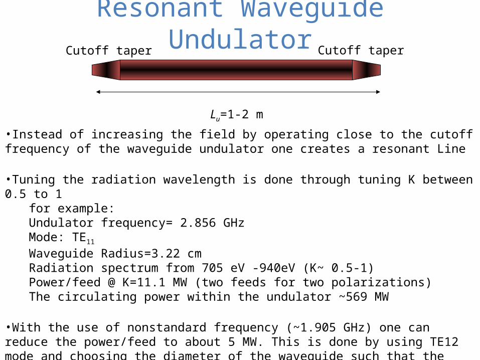
Resonant Waveguide UndulatorCutoff taper Cutoff taper
Lu=1-2 m
•Instead of increasing the field by operating close to the cutoff frequency of the waveguide undulator one creates a resonant Line
•Tuning the radiation wavelength is done through tuning K between 0.5 to 1for example:Undulator frequency= 2.856 GHzMode: TE11 Waveguide Radius=3.22 cmRadiation spectrum from 705 eV -940eV (K~ 0.5-1)Power/feed @ K=11.1 MW (two feeds for two polarizations)The circulating power within the undulator ~569 MW
•With the use of nonstandard frequency (~1.905 GHz) one can reduce the power/feed to about 5 MW. This is done by using TE12 mode and choosing the diameter of the waveguide such that the line losses is much smaller than the end losses
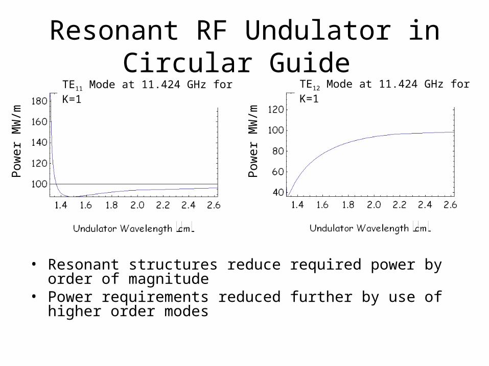
Resonant RF Undulator in Circular Guide
• Resonant structures reduce required power by order of magnitude
• Power requirements reduced further by use of higher order modes
Pow
er M
W/m
Pow
er M
W/m
TE11 Mode at 11.424 GHz for K=1 TE12 Mode at 11.424 GHz for K=1
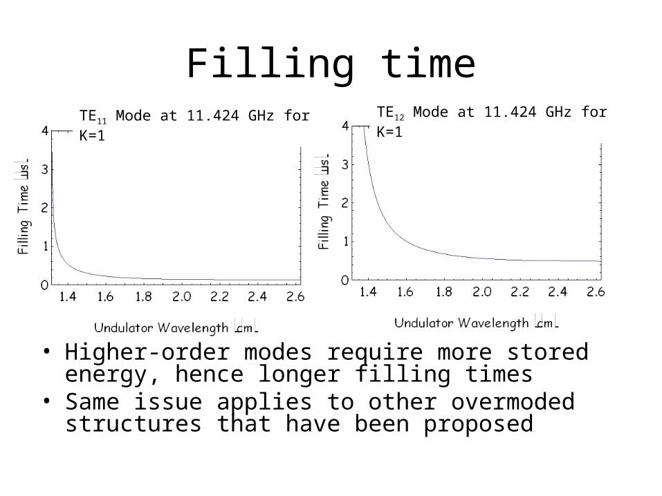
Filling time
• Higher-order modes require more stored energy, hence longer filling times
• Same issue applies to other overmoded structures that have been proposed
TE11 Mode at 11.424 GHz for K=1 TE12 Mode at 11.424 GHz for K=1
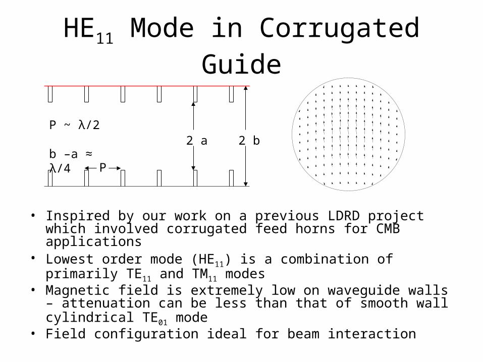
HE11 Mode in Corrugated Guide
• Inspired by our work on a previous LDRD project which involved corrugated feed horns for CMB applications
• Lowest order mode (HE11) is a combination of primarily TE11 and TM11 modes
• Magnetic field is extremely low on waveguide walls – attenuation can be less than that of smooth wall cylindrical TE01 mode
• Field configuration ideal for beam interaction
P
2 a 2 bP ~ λ/2 b –a ≈ λ/4
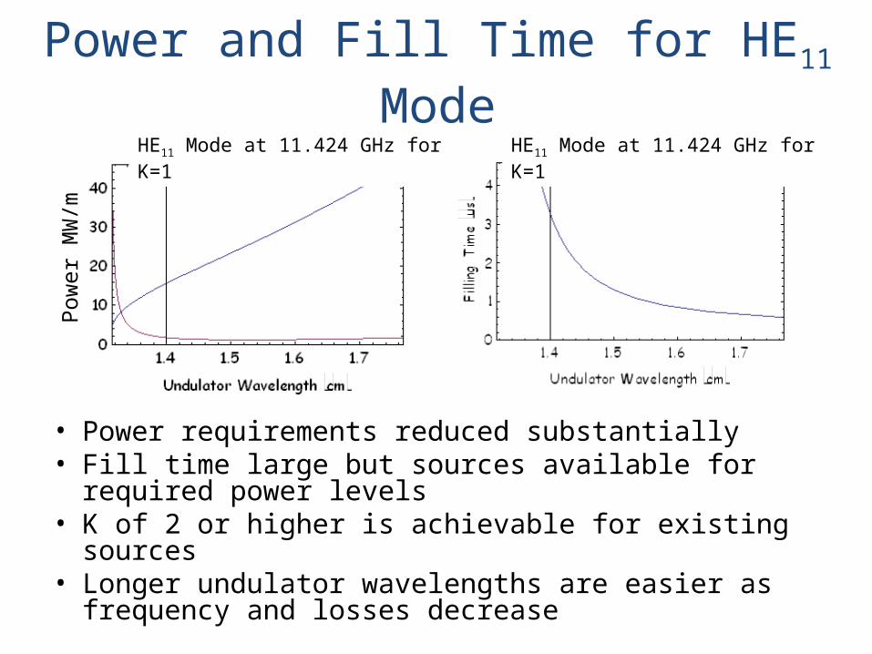
Power and Fill Time for HE11 Mode
• Power requirements reduced substantially• Fill time large but sources available for required
power levels• K of 2 or higher is achievable for existing sources• Longer undulator wavelengths are easier as
frequency and losses decrease
Pow
er M
W/m
HE11 Mode at 11.424 GHz for K=1 HE11 Mode at 11.424 GHz for K=1
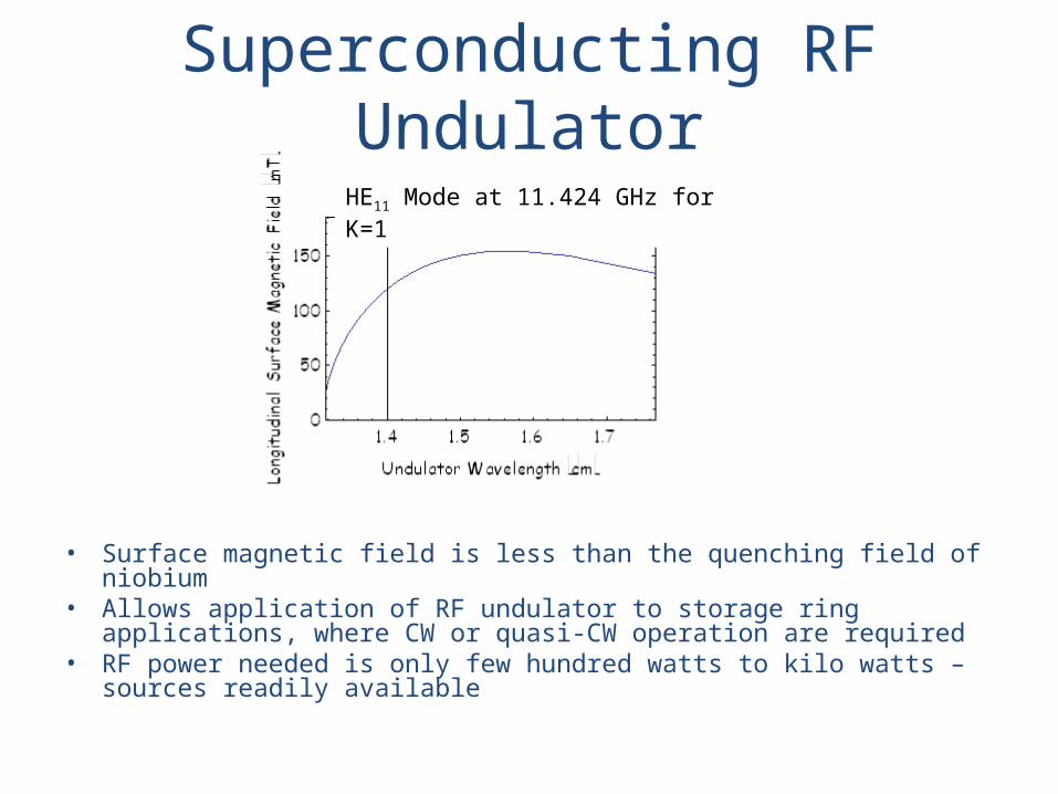
Superconducting RF Undulator
• Surface magnetic field is less than the quenching field of niobium • Allows application of RF undulator to storage ring applications,
where CW or quasi-CW operation are required• RF power needed is only few hundred watts to kilo watts – sources
readily available
HE11 Mode at 11.424 GHz for K=1
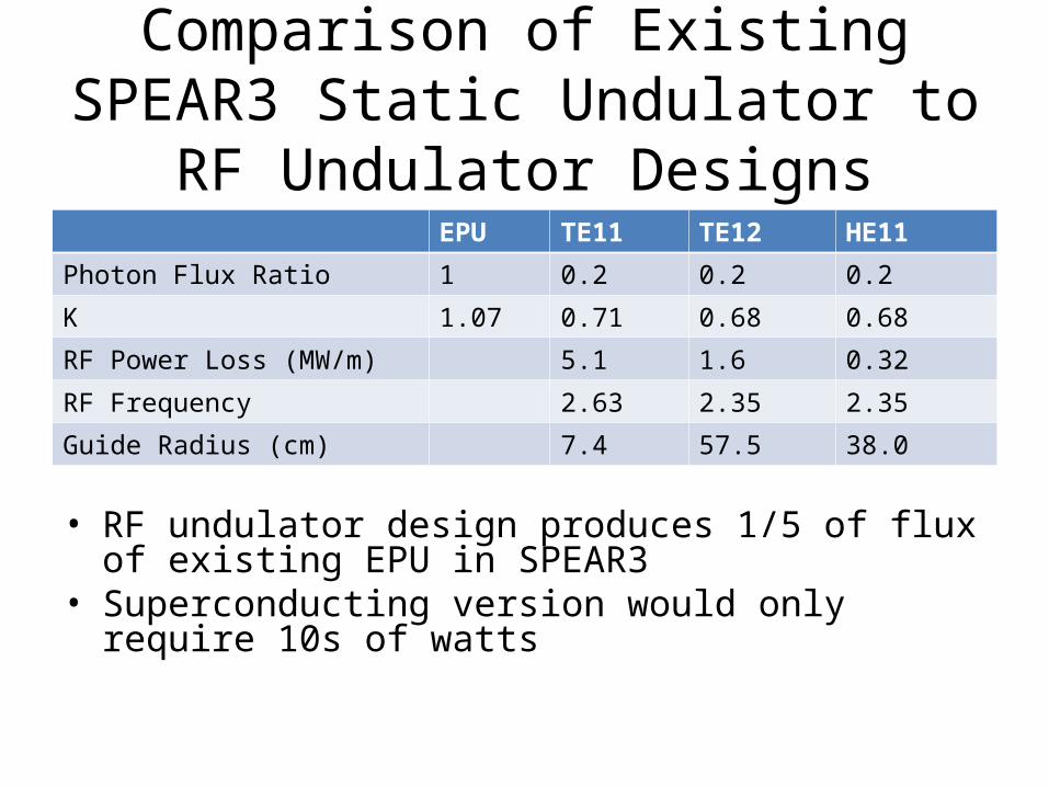
Comparison of Existing SPEAR3 Static Undulator to RF Undulator Designs
EPU TE11 TE12 HE11
Photon Flux Ratio 1 0.2 0.2 0.2
K 1.07 0.71 0.68 0.68
RF Power Loss (MW/m) 5.1 1.6 0.32
RF Frequency 2.63 2.35 2.35
Guide Radius (cm) 7.4 57.5 38.0
• RF undulator design produces 1/5 of flux of existing EPU in SPEAR3
• Superconducting version would only require 10s of watts
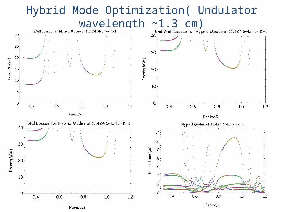
Hybrid Mode Optimization( Undulator wavelength ~1.3 cm)
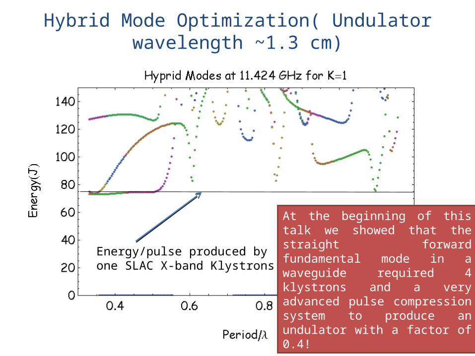
Energy/pulse produced by one SLAC X-band Klystrons
At the beginning of this talk we showed that the straight forward fundamental mode in a waveguide required 4 klystrons and a very advanced pulse compression system to produce an undulator with a factor of 0.4!
Hybrid Mode Optimization( Undulator wavelength ~1.3 cm)
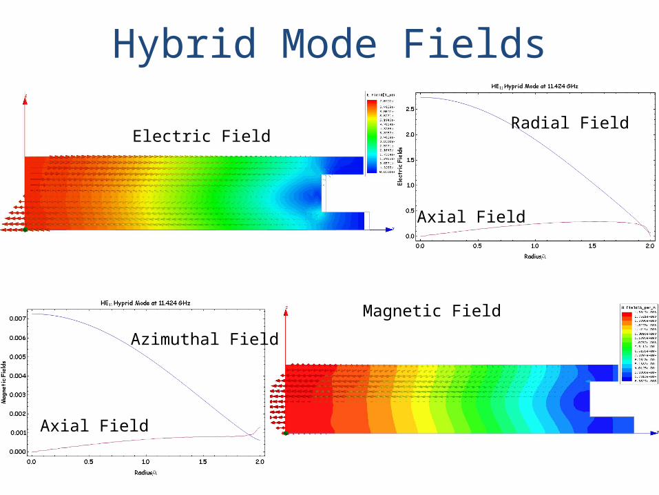
Hybrid Mode Fields
Electric Field
Magnetic Field
Radial Field
Axial Field
Azimuthal Field
Axial Field
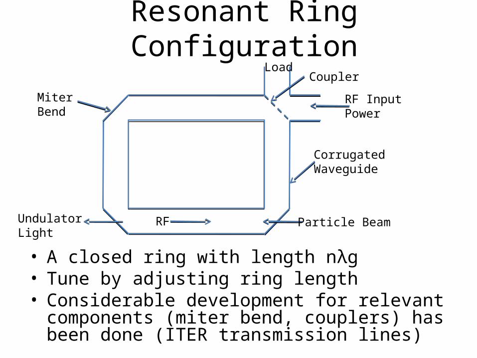
Resonant Ring Configuration
• A closed ring with length nλg• Tune by adjusting ring length• Considerable development for relevant components
(miter bend, couplers) has been done (ITER transmission lines)
Particle Beam
RF Input Power
Undulator Light
RF
CorrugatedWaveguide
Miter Bend
CouplerLoad

Future Work• Prototype design
– Refine corrugated waveguide parameters for optimal performance – Beam impedance calculations– Resonant ring / resonator design
• RF feed• Particle beam port• Low power testing of critical components
• Construction and test of undulator– HOM damping design as necessary for storage ring applications– Mechanical design– Construct and test at NLCTA– If successful apply for more funds for testing either with LCLS or SSRL
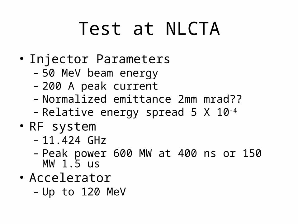
Test at NLCTA• Injector Parameters
– 50 MeV beam energy– 200 A peak current– Normalized emittance 2mm mrad??– Relative energy spread 5 X 10⁻⁴
• RF system– 11.424 GHz– Peak power 600 MW at 400 ns or 150 MW 1.5 us
• Accelerator– Up to 120 MeV
Conclusions
• Use of HE11 mode provides key to first practical application of RF undulators
• Successful development will enable design of undulators with capabilities not possible with current static undulators
• Could lead to a new class of FEL and storage ring undulators