Embed Size (px)
Citation preview

Development of RationalOverlay Design
Procedures for FlexiblePavementsSPR# 0092-00-05
Wis
cons
in H
ighw
ay R
esea
rch
Prog
ram
WHRP 05-12
James A. CrovettiDepartment of Civil and Environmental Engineering
Marquette University
September 2005

WISCONSIN HIGHWAY RESEARCH PROGRAM #0092-00-05 DEVELOPMENT OF RATIONAL OVERLAY DESIGN PROCEDURES FOR FLEXIBLE PAVEMENTS FINAL REPORT by James Crovetti, Ph.D., Principal Investigator Marquette University Department of Civil & Environmental Engineering P.O. Box 1881 Milwaukee, WI 53201-1881 Submitted to: WISCONSIN DEPARTMENT OF TRANSPORTATION September 2005

ii
DISCLAIMER
This research was funded through the Wisconsin Highway Research Program by the Wisconsin
Department of Transportation and the Federal Highway Administration under Project # 0092-00-
05. The contents of this report reflect the views of the authors who are responsible for the facts
and the accuracy of the data presented herein. The contents do not necessarily reflect the official
views of the Wisconsin Department of Transportation or the Federal Highway Administration at
the time of publication.
This document is disseminated under the sponsorship of the Department of
Transportation in the interest of information exchange. The United States Government assumes
no liability for its contents or use thereof. This report does not constitute a standard,
specification or regulation.
The United States Government does not endorse products or manufacturers. Trade and
manufacturers’ names appear in this report only because they are considered essential to the object
of the document.
ACKNOWLEDGEMENTS
The authors greatly appreciate the support, advice, and technical contributions received
from members of the WHRP Flexible Pavement Technical Oversight Committee during the
conduct of this study.

iii
Technical Report Documentation Page
1. Report No. WHRP 05-12
2. Government Accession No
3. Recipient’s Catalog No
4. Title and Subtitle Development of Rational Overlay Design Procedures for Flexible Pavements
5. Report Date September 2005 6. Performing Organization Code
7. Authors James A. Crovetti
8. Performing Organization Report No.
9. Performing Organization Name and Address Marquette University P.O. Box 1881 Milwaukee, WI 53201-1881
10. Work Unit No. (TRAIS) 11. Contract or Grant No. WHRP Project 0092-00-05
12. Sponsoring Agency Name and Address Wisconsin Department of Transportation Division of Transportation Infrastructure Development Research Coordination Section 4802 Sheboygan Avenue Madison, WI 53707
13. Type of Report and Period Covered
Final Report, Jan 2000 – Sep 2005 14. Sponsoring Agency Code
15. Supplementary Notes 16. Abstract This report presents the findings of a research study conducted to develop procedures for the design of structural HMA overlays over existing flexible pavements in Wisconsin. The recommended procedures are presented in a hierarchal approach to allow the user the flexibility of estimating the effective structural number of an in-place HMA pavement based on visual and/or nondestructive deflection testing data and to develop overlay thickness requirements based on the structural deficiency approach. Techniques for estimating the effective structural number of an existing pavement based on surface deflection are presented. The equations presented in the 1993 AASHTO Design Guide were modified to enhance their applicability. Alternate deflection-based techniques were also developed to allow for the estimation of effective structural number without pavement thickness information. The overlay design procedures were developed to maintain consistency with the current WisDOT practice of new flexible pavement design based on the 1972 AASHO design equation. 17. Key Words HMA Pavements, Falling Weight Deflectometer,
Effective Structural Number, Overlay Design
18. Distribution Statement No restriction. This document is available to the public through the National Technical Information Service,5285 Port Royal Road, Springfield VA 22161
19. Security Classif.(of this report) Unclassified
19. Security Classif. (of this page) Unclassified
20. No. of Pages 59
21. Price
Form DOT F 1700.7 (8-72) Reproduction of completed page authorized

iv
EXECUTIVE SUMMARY
Project Summary
This research study consists of developing rational overlay design procedures for flexible
pavements that are consistent with current procedures utilized by the Wisconsin Department of
Transportation for the design of new Hot Mix Asphalt (HMA) pavements. The recommended
procedures are presented in a hierarchal approach to allow the user the flexibility of estimating
the effective structural number of an in-place HMA pavement based on visual and/or
nondestructive deflection testing data and to develop overlay thickness requirements based on
the structural deficiency approach. The procedures are recommended for the design of structural
HMA overlays on existing flexible pavement systems.
Project Background
The current WisDOT practice for the design of structural asphalt concrete overlays on
existing flexible pavements pavement is largely empirical. Little guidance is provided in Procedure
14-10-30 of the WisDOT Facilities Development Manual (FDM) for quantifying the structural
integrity of existing flexible pavement systems. This results in overlay thicknesses which can vary
from project to project even when other pavement design parameters are the same, potentially
resulting in rehabilitated pavement sections that do not perform as desired or a less than optimum
use of valuable resources. This research was conducted to provide a consistent, objective
methodology for determining the required thickness of structural HMA overlays to prolong the
service life of existing flexible pavement systems.

v
Process
Literature was reviewed from various national sources detailing the best practices for
design structural HMA overlays of existing flexible pavements. Overlay design methodologies
utilized by surrounding states were also investigated. Literature relating to the conduct of visual
and nondestructive deflection testing surveys was also reviewed to develop protocol beneficial to
the study objectives. After considering all factors, it was deemed appropriate to develop overlay
design methodologies that would be consistent with the current WisDOT practice for the design
of new flexible pavements based on the structural number concept. A significant effort was
expended on the development and analysis of deflection data generated by computer modeling of
a factorial of flexible pavement structures. Statistical analyses of all generated data were
conducted to develop predictive equations for estimating the effective structural number of
existing HMA pavements.
Findings
The analyses conducted as part of this research resulted in the following findings:
(1) The design of structural HMA overlays of existing flexible pavements can be integrated
within current WisDOT procedure for the design of new flexible pavements by utilizing the
structural deficiency approach. This process establishes the required overlay thickness based on the
difference between the effective structural number, SNeff, of the existing pavement existing and the
structural number required for a new flexible pavement design.
(2) The SNeff of existing flexible pavements can be established based on deflections,
distress, or ride quality. The use of deflection data is considered appropriate for pavements with

vi
design traffic loadings in excess of 1 million ESALs. For lightly trafficked pavements the SNeff may
be developed without the use of deflection data. The accuracy of SNeff estimations can be improved
by including pavement layer thickness data obtained through selective coring; however, all analysis
techniques have associated errors.
(3) Modified deflection-based SNeff analysis procedures were developed based techniques
presented in the 1993 AASHTO Guide for the Design of Pavement Structures. These procedures
provided the best correlations between SNeff and input SN using deflection data generated during
computer modeling of a large pavement factorial. These procedures are somewhat cumbersome to
apply and are best suited for analysis when pavement layer thicknesses are known. Based on the
results presented, these procedures were shown to provide overlay thickness recommendations
which were within ½ inch of “truth”, as represented by exact component analysis of the pavement
structures investigated during computer modeling, for 90% of the structures investigated.
(4) Alternative deflection-based analysis techniques developed as part of this research were
also shown to provide reasonable correlations between SNeff and input SN using deflection data
generated during computer modeling of the large pavement factorial. These procedures are easier to
apply and do not require knowledge of the in-place pavement layer thicknesses. Based on the results
presented, these procedures were shown to provide overlay thickness recommendations which were
within ½ inch of “truth” for 40% of the pavement structures investigated and within 1 inch of truth
for 84% of the structures. These values were shown to be comparable to the modified AASHTO
approach if the assumed pavement thickness is in error by 10%.

vii
Recommendations
Based on the findings from this research, it is recommended that the structural deficiency
approach be implemented for the design of structural HMA overlay thickness requirements for
existing flexible pavements. The procedures presented in this report are considered appropriate for
establishing thickness requirement for structural HMA overlays. Thickness requirements resulting
from the application of these methods are not intended to supersede minimum/maximum HMA layer
thickness guidelines as detailed in the WisDOT Standard Specifications, Section 460.3.2.
The structural deficiency approach utilizes both the effective structural number, SNeff, of the
existing pavement and the structural number required for new design. It is recommended that the
deflection-based analysis procedures presented in Section 2.4.5 of this report be promoted to
estimate the effective structural number, SNeff, of the existing flexible pavement that are projected to
carry at least 1 million ESALs after overlay. During initial implementations, both the modified
AASHTO and revised AUPP-Eri should be utilized to establish SNeff and asses the impacts of
analyses with and without available coring data.
For lightly trafficked pavements with less than 1 million design ESALs, it is recommended
that the SNeff be established based on the deflection based-analysis techniques or a component
analysis based on layer thickness and existing pavement distress. The guidelines presented by
AASHTO for the selection of structural layer coefficients based on existing distress are
recommended for use when deflection data is unavailable and the component analysis is selected.
The recommended overlay thickness design procedures are compatible with the current
WisDOT procedures for the design of new flexible pavements, as published within Procedure 14-10-

viii
5 of the Facilities Development Manual (FDM). When deflection data are utilized, the field
subgrade modulus is determined directly from deflections. This value may require seasonal
adjustments depending on the time of deflection testing as well as conversion to a representative soil
support value following standard WisDOT procedures.
The overlay design procedures presented in this report may be utilized to develop thickness
requirements for any user-supplied design life. The practical limitation for these procedures is a 20-
year design life which is consistent with the maximum design life currently assumed for the design
of traditional HMA pavements in Wisconsin following FDM Procedure 14-10-5. Shorter design
lives can be considered by developing new pavement SN requirements using projected traffic levels
within the 1972 AASHTO equation currently used by WisDOT.

ix
TABLE OF CONTENTS DISCLAIMER .............................................................................................................................. ii ACKNOWLDEGEMENTS ........................................................................................................ ii TECHNICAL REPORT DOCUMENTATION PAGE ........................................................... iii EXECUTIVE SUMMARY ........................................................................................................ iv 1.0 INTRODUCTION...................................................................................................................1
1.1 Background and Problem Statement.........................................................................1 1.2 Overlay Design Methodologies ...................................................................................2
1.2.1 Structural Deficiency Approach....................................................................3 1.2.2 Visual Pavement Assessments .......................................................................4 1.2.3 Nondestructive Deflection Testing Assessments...........................................8 1.2.4 Remaining Life Assessments .......................................................................10 1.2.5 Maximum Deflection Approach .................................................................13
1.3 Overlay Design Methods Used in Surrounding States ..........................................14 1.3.1 Illinois Department of Transportation........................................................14 1.3.2 Indiana Department of Transportation.......................................................15 1.3.3 Iowa Department of Transportation ...........................................................16 1.3.4 Michigan Department of Transportation....................................................17 1.3.5 Minnesota Department of Transportation ..................................................17 1.3.6 Summary of Surrounding States .................................................................18
2.0 RECOMMENDED DATA ELEMENTS.............................................................................20
2.1 Introduction................................................................................................................20 2.2 Effective Structural Number of Existing Pavement ...............................................20 2.3 Pavement Condition Measures .................................................................................22 2.4 Pavement Deflection Measures.................................................................................24
2.4.1 SNeff Predictions Based on AASHTO Equations........................................27 2.4.2 SNeff Predictions Based on Deflection Algorithms.....................................30 2.4.3 SNeff Predictions Based on Asphalt Institute Procedures ..........................35 2.4.4 Combined Overlay Design Approach..........................................................37 2.4.5 Preferred Deflection-Based Methods ..........................................................40
3.0 OVERLAY DESIGN CONSIDERATIONS........................................................................49
3.1 Introduction................................................................................................................49 3.2 Deflection Testing Procedures ..................................................................................50 3.3 Project Analysis..........................................................................................................53

x
TABLE OF CONTENTS (Cont.) 4.0 FINDINGS AND RECOMMENDATIONS ........................................................................55
4.1 Summary of Findings ................................................................................................55 4.2 Recommendations ......................................................................................................57
5.0 REFERENCES.......................................................................................................................59

xi
LIST OF FIGURES Figure 1.2.1 Remaining Life Based on PSI and SNo ...................................................................12 Figure 2.3.1 PDI versus Age for WisDOT Performance Data .....................................................23 Figure 2.3.2 SDI versus Age for WisDOT Performance Data .....................................................23 Figure 2.3.3 SDI versus PDI Values .............................................................................................25 Figure 2.3.4 IRI versus Age for WisDOT Performance Data .......................................................25 Figure 2.4.1 Effective SN versus Input SN Based on Current AASHTO Equation......................28 Figure 2.4.2 Effective SN versus Input SN Based on Revised AASHTO ....................................31 Figure 2.4.3 Effective SN versus Input SN Based on Modified AASHTO...................................31 Figure 2.4.4 Effective SN versus Input SN Based on Preliminary Eri-AUPP ..............................34 Figure 2.4.5 Effective SN versus Input SN Based on Modified Eri-AUPP ..................................34 Figure 2.4.6 Effective SN versus Input SN Based on AI ..............................................................36 Figure 2.4.7 Allowable ESALs versus Maximum Deflection .......................................................38 Figure 2.4.8 Allowable ESALs versus Maximum Deflection .......................................................38 Figure 2.4.9 Effective SN Based on AI Analysis versus Input SN ...............................................41 Figure 2.4.10 Overlay Thickness Estimation Error Based on AI Analysis versus Input SN ........41 Figure 2.4.11 SNeff Estimation Errors Based on Modified AASHTO .........................................42 Figure 2.4.12 SNeff Estimation Errors Based on Modified AASHTO .........................................42 Figure 2.4.13 Overlay Thickness Estimation Errors Based on Modified AASHTO.....................43 Figure 2.4.14 Overlay Thickness Estimation Errors Based on Modified AASHTO.....................43 Figure 2.4.15 SN Estimation Errors Based on Modified AASHTO with Decreased Thickness...45 Figure 2.4.16 Overlay Thickness Errors Based on Modified AASHTO with Decreased Thickness........45 Figure 2.4.17 SN Estimation Errors Based on Modified Eri-AUPP .............................................47 Figure 2.4.18 SN Estimation Errors Based on Modified Eri-AUPP .............................................47 Figure 2.4.19 Overlay Thickness Errors Based on Modified Eri-AUPP.......................................48 Figure 2.4.20 Overlay Thickness Errors Based on Modified Eri-AUPP.......................................48 Figure 3.2.1 Maximum Deflection Temperature Adjustment Factor ............................................52

xii
LIST OF TABLES Table 1.2.1 AI Conversion Factors for Determining Effective Thickness .....................................6 Table 1.2.2 Suggested AASHTO Layer Coefficients .....................................................................7 Table 1.3.1 Summary of Overlay Design Procedures Used in Surrounding States ......................19 Table 2.2.1 Example Decision Matrix for Establishing SNeff .....................................................21 Table 2.4.1 KENLAYER Pavement Factorial ..............................................................................26 Table 2.4.2 Coefficients and Exponents for Equation 2.16 ...........................................................39

1
CHAPTER 1 INTRODUCTION
1.1 Background and Problem Statement
The current WisDOT practice for the design of structural asphalt concrete overlays on
existing flexible pavements pavement is largely empirical. Little guidance is provided in Procedure
14-10-30 of the WisDOT Facilities Development Manual for quantifying the structural integrity of
existing flexible pavement systems. This results in overlay thicknesses which can vary from project
to project even when other pavement design parameters are the same, potentially resulting in
rehabilitated pavement sections that do not perform as desired or a less than optimum use of
valuable resources.
The primary objectives of this research are to (1) develop a rational procedure for
quantifying the effective structural capacity of existing flexible pavements, (2) recommend
guidelines for the collection and use of data to determine the effective structural capacity of existing
flexible pavements, (3) recommend procedures for designing structural asphalt concrete overlays on
existing flexible pavement systems, and (4) recommend guidelines for implementing these
procedures throughout the State of Wisconsin. These products will provide a consistent, objective
methodology for determining the required thickness of asphalt concrete overlays to increase the
structural capacity of existing flexible pavement systems.
This report presents the findings of a literature review of published flexible pavement overlay
design procedures as well as the results of a survey of overlay design procedures used in States
surrounding Wisconsin. Based on these findings, recommendations for key data elements to be
included in the WisDOT overlay design procedures are presented.

2
1.2 Overlay Design Methodologies
HMA overlays are predominantly used to improve the structural capacity and/or functional
requirements (i.e., skid resistance or ride quality) of existing pavements. Overlays may be required
due to excessive deterioration of the existing pavement or because current or revised traffic
projections indicate the existing pavement is deficient in structural capacity to provide adequate
performance. Overlay thicknesses may be specified based on simple engineering judgment or policy
decisions or designed based on structural deficiency, limiting deflection, or limiting fatigue damage
approaches.
The most commonly used overlay design approach is the structural deficiency approach,
whereby the overlay must satisfy a deficiency between the required traffic capacity of an existing
pavement over some future time period and the actual traffic capacity of that pavement over the
same time period. The current AASHTO overlay design procedures (1) are based on the structural
deficiency concept, as are other overlay design procedures developed by agencies such as the Corps
of Engineers (2) and the Asphalt Institute (3). Structural deficiency approaches have dominated
overlay design to date because widely accepted performance models (such as the AASHTO models)
are available for asphalt pavements but generally acceptable performance models are not available
for overlaid pavements.
The second most commonly used overlay design method is based on the maximum deflection
approach developed by the Asphalt Institute (3). In this method, total pavement deflection is related
to the pavement=s service life, expressed in terms of allowable 18-kip ESALs. Overlay thickness
designs are developed to reduce total pavement deflections to tolerable levels based on the projected
ESALs over the design analysis period.

3
A third overlay design method which is gaining wide acceptance is based on the limiting
fatigue damage concept using mechanistic principles. In this approach, a stress-strain analysis of the
existing pavement structure is conducted and the remaining service life, in terms of fatigue cracking
and/or subgrade rutting, is estimated based on empirical transfer functions. Overlay thickness
designs are developed to limit fatigue cracking and/or rutting of the overlaid pavement to tolerable
levels based on the projected traffic over the design analysis period.
The focus of this research is the development of objective procedures for designing structural
HMA overlays on existing flexible pavements which are 1) compatible with current WisDOT
pavement design methods, and 2) utilize pavement performance data (i.e., IRI PSI, PDI, and
deflections) commonly collected in Wisconsin. A framework for these procedures, based on
published design methods, is presented in the following sections.
1.2.1 Structural Deficiency Approach
The basic concept of the structural deficiency approach is that the HMA overlay represents
the difference between the structure required for a new pavement and the existing pavement
structure. Inherent in this approach is the establishment of the in situ pavement=s structural capacity,
commonly termed the effective structural capacity of the existing pavement. This effective
structural capacity must be established within the context of the design method used for determining
the required new pavement structure. In other words, if the new pavement design is expressed in
terms of a full-depth HMA layer thickness, then the effective structural capacity must be converted
to an equivalent HMA layer thickness. On the other hand, if a new pavement structure is expressed
in terms of a required structural number (SN), the in situ structural capacity must be converted to an
effective SN.

4
The 1993 AASHTO Design Guide (1) provides three approaches for estimating the effective
structural capacity of in situ flexible pavements, provided in terms of the effective structural number,
SNeff. These methods are based on visual assessment, nondestructive deflection testing, and/or
remaining life analyses. Each analysis method is compatible with the SN pavement design concept
promoted by AASHTO and used by WisDOT. Deflection testing is strongly recommended for this
analysis.
The Asphalt Institute (3) provides two methods for estimating the effective structural
capacity of in situ flexible pavements, provided in terms of the effective HMA thickness of the in
situ pavement. These methods are based on the Present Serviceability Index (PSI) of the existing
pavement or a component analysis based on visual distress.
The U.S. Army Corps of Engineers (2) utilizes the existing HMA pavement thickness
without alteration for condition assessments when determining overlay thickness requirements.
1.2.2 Visual Pavement Assessments
A visual pavement assessment requires a detailed condition survey of pavement distress to
identify the type, amount, severity, and location of key distress types. Subdrainage surveys and
materials coring and testing are also recommended as part of this assessment. The results of the
condition survey are used by AASHTO to conduct a component analysis of the existing pavement
using the structural number equation:
SNeff = ai Di mi Eq. 1.1
where: Di = thickness of in situ pavement layer i ai = corresponding structural coefficient of layer i mi, = drainage coefficient for layer i

5
The Asphalt Institute utilizes condition information to compute the effective thickness of the
in situ pavement using the equation:
he = Σ hi Ci Eq. 1.2
where: he = total effective HMA thickness of existing pavement hi = thickness of pavement layer i Ci = HMA conversion factor for pavement layer i
Limited guidance is provided for selecting appropriate structural layer coefficients or layer
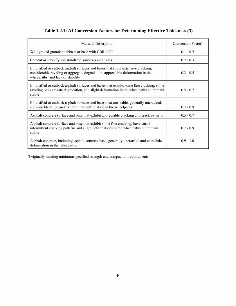
conversion factors. Tables 1.2.1 and 1.2.2 provide appropriate layer coefficients suggested by AI
(3) and AASHTO (1).
Procedures for determining conversion factors for full-depth HMA pavements, based on the
PSI of the existing pavement, are also provided by AI. For conservative analysis, this conversion
factor can be computed for existing PSI values between 1.5 and 3.9 using the equation:
CF = 0.166 + 0.213 PSI Eq. 1.3
where: CF = full-depth HMA conversion factor PSI = existing PSI
6
Table 1.2.1: AI Conversion Factors for Determining Effective Thickness (3)
Material Description
Conversion Factora Well graded granular subbase or base with CBR > 20
0.1 - 0.2
Cement or lime-fly ash stabilized subbases and bases
0.2 - 0.3
Emulsified or cutback asphalt surfaces and bases that show extensive cracking, considerable raveling or aggregate degradation, appreciable deformation in the wheelpaths, and lack of stability
0.3 - 0.5
Emulsified or cutback asphalt surfaces and bases that exhibit some fine cracking, some raveling or aggregate degradation, and slight deformation in the wheelpaths but remain stable
0.5 - 0.7
Emulsified or cutback asphalt surfaces and bases that are stable, generally uncracked, show no bleeding, and exhibit little deformation in the wheelpaths
0.7 - 0.9 Asphalt concrete surface and base that exhibit appreciable cracking and crack patterns
0.5 - 0.7
Asphalt concrete surface and base that exhibit some fine cracking, have small intermittent cracking patterns and slight deformations in the wheelpaths but remain stable
0.7 - 0.9
Asphalt concrete, including asphalt concrete base, generally uncracked and with little deformation in the wheelpaths
0.9 - 1.0
aOriginally meeting minimum specified strength and compaction requirements

7
Table 1.2.2: Suggested AASHTO Layer Coefficients (1)
Material
Surface Condition
Coefficient Little or no alligator cracking and/or only low severity transverse cracking
0.35 - 0.40 <10% low severity alligator cracking and/or <5% medium and high severity transverse cracking
0.25 - 0.35 >10% low severity alligator cracking and/or <10% medium and high severity alligator cracking and/or >5-10% medium and high severity transverse cracking
0.20 - 0.30
>10% medium severity alligator cracking and/or <10% high severity alligator cracking and/or >10% medium and high severity transverse cracking
0.14 - 0.20
AC Surface
>10% high severity alligator cracking and/or >10% high severity transverse cracking
0.08 - 0.15 Little or no alligator cracking and/or only low severity transverse cracking
0.20 - 0.35 <10% low severity alligator cracking and/or <5% medium and high severity transverse cracking
0.15 - 0.25 >10% low severity alligator cracking and/or <10% medium and high severity alligator cracking and/or >5-10% medium and high severity transverse cracking
0.15 - 0.20
>10% medium severity alligator cracking and/or <10% high severity alligator cracking and/or >10% medium and high severity transverse cracking
0.10 - 0.20
Stabilized Base
>10% high severity alligator cracking and/or >10% high severity transverse cracking
0.08 - 0.15 No evidence of pumping, degradation, or contamination by fines
0.10 - 0.14
Granular Base or Subbase
Some evidence of pumping, degradation, or contamination by fines
0.0 - 0.10
8
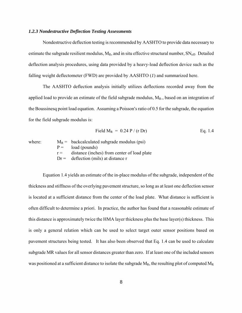
1.2.3 Nondestructive Deflection Testing Assessments
Nondestructive deflection testing is recommended by AASHTO to provide data necessary to
estimate the subgrade resilient modulus, MR, and in situ effective structural number, SNeff. Detailed
deflection analysis procedures, using data provided by a heavy-load deflection device such as the
falling weight deflectometer (FWD) are provided by AASHTO (1) and summarized here.
The AASHTO deflection analysis initially utilizes deflections recorded away from the
applied load to provide an estimate of the field subgrade modulus, MR., based on an integration of
the Boussinesq point load equation. Assuming a Poisson=s ratio of 0.5 for the subgrade, the equation
for the field subgrade modulus is:
Field MR = 0.24 P / (r Dr) Eq. 1.4
where: MR = backcalculated subgrade modulus (psi) P = load (pounds) r = distance (inches) from center of load plate Dr = deflection (mils) at distance r
Equation 1.4 yields an estimate of the in-place modulus of the subgrade, independent of the
thickness and stiffness of the overlying pavement structure, so long as at least one deflection sensor
is located at a sufficient distance from the center of the load plate. What distance is sufficient is
often difficult to determine a priori. In practice, the author has found that a reasonable estimate of
this distance is approximately twice the HMA layer thickness plus the base layer(s) thickness. This
is only a general relation which can be used to select target outer sensor positions based on
pavement structures being tested. It has also been observed that Eq. 1.4 can be used to calculate
subgrade MR values for all sensor distances greater than zero. If at least one of the included sensors
was positioned at a sufficient distance to isolate the subgrade MR, the resulting plot of computed MR

9
vs sensor position is typically concave upwards, and the minimum value of MR can be determined by
inspection and used as a reasonable estimate of the field MR. When the outer sensor yields the
minimum calculated MR value, it may be assumed that this sensor was not positioned sufficiently far
from the load plate to isolate the subgrade MR and analysis results should then be viewed with
caution.
It should also be noted that the concave upwards trend of most subgade MR vs sensor
location plots indicates the subgrade materials are stress-dependent, which is typically expected for
fine-grained, stress-softening subgrade materials. For this reason, computed MR values for sensor
placements greater than that required to isolate the subgrade MR are higher due to lower stress states
at deeper levels in the subgrade.
The 1993 AASHTO Guide also presents the following equation for D0, the deflection
measured at the center of the FWD load plate:
D0 = 1.5 pa {[1/(MR ((1+((Tp/a)(Ep/MR)1/3)2))2)] + [(1-(1/((1 + (Tp/a)2 )2 )))/Ep ]} Eq. 1.5
Where: D0 = maximum deflection (at center of load plate) (mils) p = FWD plate pressure (psi) a = FWD plate radius (in) MR = in-place subgrade modulus (psi) Tp = total thickness of pavement structure above subgrade (in) Ep = effective elastic modulus of the pavement structure (psi)
With the maximum measured deflection, D0, the FWD plate pressure and radius, and the
pavement thickness known, Eq. 1.5 can be used to solve for the effective pavement modulus Ep.
Thus, combined use of Eqs. 1.4 and 1.5 can provide the solution to the backcalculation of elastic
moduli for a two-layer system, using two deflection measurements (D0 and Dr) to solve for two
unknowns, namely MR and Ep. Such a solution can be implemented in a computer spreadsheet

10
program; however, Eq. 1.5 cannot be rearranged to solve for Ep directly. Ep can, however, be
determined by iteration, that is, varying Ep until the calculated D0 matches the measured D0. This
can also be accomplished using goal seeking functions available within spreadsheet applications.
The effective pavement modulus can then be used to estimate the effective structural number
of the in-place pavement, SNeff, using the equation:
SNeff = 0.0045 Ep1/3Tp Eq. 1.6
where: SNeff = effective structural number of existing pavement Tp = total pavement thickness, inches Ep = effective pavement modulus, psi
Once SNeff is established, the required SN for the overlay, and hence the required overlay
thickness is simply computed as:
SNOL = aOL * DOL = SNf - SNeff Eq. 1. 7
where: SNOL = structural number required for new pavement aOL = structural coefficient for the HMA overlay DOL = HMA overlay thickness SNf = structural number required for new pavement SNeff = effective structural number of in situ pavement
1.2.4 Remaining Life Assessments
Techniques for estimating the effective structural capacity of an existing pavement based on
remaining life estimates are provided by AASHTO and AI. The AASHTO procedures (1,4) utilize a
past traffic analysis or an existing PSI analysis for this purpose while the AI procedures (3) utilize
only deflection testing.
The AASHTO remaining life assessment procedures based on past traffic are most

11
appropriate for estimating the remaining life of an original flexible pavement, i.e., no overlay has
been applied. Where available, historic traffic data is used to compute ESAL applications to date.
The designer must also determine the total ESALs to failure (PSI = 1.5) for the original pavement.
Together, these two ESAL values are used to compute the percent remaining life using the equation
(1):
RL = 100 [ 1 - Np / N1.5 ] Eq. 1.8
where: RL = percent remaining life NP = total ESALs to date N1.5 = total ESALs to PSI=1.5
The effective structural number, SNeff, of the existing pavement is computed based on the
original pavement structural number, SNO, and a condition factor, CF, using the equation:
SNeff = CF * SNO Eq. 1.9
The condition factor may be computed using the equation:
. CF = 0.5 + 0.09 Log RL + 0.08 (Log RL)2 Eq. 1.10
The previous edition of the AASHTO Design Guide (4) also provided a method for
estimating the remaining life of a pavement based on the Present Serviceability Index (PSI) and
initial Structural Number, SNo, of the pavement, as shown in Figure 1.2.1.

12
Figure 1.2.1: Remaining Life Based on PSI and SNo (4)
Surface deflections are also used within the AI design method to provide an estimate of the
remaining life of a pavement. The AI method was originally developed for use with the Benkelman
beam using a rebound deflection test procedure. In this process, at least 10 deflection tests are
required within a given design section and the design rebound deflection is calculated as the average
plus two standard deviations, corrected for temperature and seasonal effects. The remaining life of
the pavement is then computed by the equation:
ESALr = (1.0363 / δrd)4.1017 Eq. 1.11
where: ESALr = remaining life ESALs δrd = design rebound deflection, inches

13
1.2.5 Maximum Deflection Approach
The maximum deflection approach, which is promoted by the Asphalt Institute (AI), is based
on the concept that structural overlays are required to strengthen weak pavement systems to reduce
pavement deflections to tolerable limits based on projected future traffic applications. This method
was originally developed for use with the Benkelman beam using the rebound deflection test
procedure discussed previously. The design rebound deflection is first used to estimate an
equivalent pavement modulus for the in-place pavement system using the equation (3):
Ep = 1.5 pa / δrd Eq 1.12
where: Ep = equivalent pavement modulus, psi p = contact pressure of load, psi a = radius of load, inches δrd = design rebound deflection, inches
Equation 1.12 is based on the assumption that the in-place pavement system can be modeled
as an equivalent homogeneous half-space with a Poisson=s ratio of 0.5. Based on the projected
ESALs after overlay, the allowable pavement deflection is computed using the alternate form of
Equation 1.11 (3):
δall = 1.0363 (ESALOL)-0.2438 Eq. 1.13
where: δall = allowable pavement deflection, inches ESALOL = projected ESALs after overlay
Based on an assumed modulus and thickness for the HMA overlay, the expected deflection
after overlay can be calculated using the previously determined Ep value using the equation (3):

14
δOL = (1.5pa/Ep)*[{1-(1+.8(hOL/a)2)-0.5}(Ep/EOL) + {1+(.8(hOL/a)(EOL/Ep)1/3)2}-0.5] Eq. 1.14
where: δOL = expected deflection after overlay, inches Ep = equivalent modulus of in-place pavement, psi hOL = assumed overlay thickness, inches a = radius of applied load, inches EOL = assumed modulus of HMA overlay, psi
Equation 1.14 can be solved iteratively to determine the required overlay thickness, hOL, to
limit the expected post-overlay deflection, δOL, to the allowable deflection, δall, computed by
Equation 1.13.
1.3 Overlay Design Methods Used in Surrounding States
A survey was conducted during the early phase of this project to identify key design
engineers in States surrounding Wisconsin and to determine their current procedures utilized for
overlay design. Prior to the initiation of this survey, a questionnaire was prepared to catalogue
overlay design procedures utilized and to identify key data elements used for the characterizing the
existing pavement structure. This questionnaire was discussed during initial phone contacts with the
key design engineers and responses entered by the Marquette research staff. The completed
questionnaires were then forwarded to the respective design engineers for verification and revision,
as required. Revised questionnaires were returned by all design engineers contacted. This section
presents a summary of the responses received.
1.3.1 Illinois Department of Transportation
Information relevant to the Illinois Department of Transportation (IDOT) procedures was
provided by Mr. David Lippert. IDOT promotes the use of the Asphalt Institute=s (AI) maximum
deflection approach for establishing structural overlay thickness requirements. Based on projected

15
traffic levels, overlay thicknesses are selected to reduce maximum surface deflections to tolerable
levels using standard AI nomographs.
Surface deflections are obtained using a falling weight deflectometer. Deflection tests are
conducted within the outer wheelpath of each travel lane using an applied load of approximately
9,000 lbs. A minimum of 30 tests per direction of travel are obtained, with a maximum test interval
of 0.1 miles. Recorded maximum deflections are normalized to a 9,000 lb load and adjusted to
represent critical season Benkelman beam rebound deflections at a standard pavement temperature
of 70 oF using the formula:
BBD = 1.6 FWD x TAF x CSAF Eq. 1.15
where: BBD = Benkelman beam rebound deflection, inches FWD = normalized maximum FWD deflection, inches @ 9,000 lb load TAF = temperature adjustment factor CSAF = critical season adjustment factor
The deflection adjustment factors are established following standard AI procedures.
Temperature adjustment factors are established based on the pavement thickness, the air and
pavement surface temperatures recorded during testing, and the previous 5-day mean air
temperature. Critical season adjustment factors are established based on soil type, pavement
location, and time of testing using IDOT correlations.
The adjusted Benkelman beam deflections are utilized to compute the average deflection and
standard deviation within the design section. These values are used to compute the representative
rebound deflection, RRD, following standard AI procedures.
1.3.2 Indiana Department of Transportation
Information relevant to the Indiana Department of Transportation (InDOT) procedures was

16
provided by Mr. Kumar Dave. InDOT promotes the use of the 1993 AASHTO procedures for
determining overlay thickness requirements. However, for most applications, a visual assessment of
distress data is used to indicate the need for an overlay and overlay thicknesses are specified based
on engineering judgment. Surface deflections obtained with a falling weight deflectometer are
utilized on a limited basis to establish both the design subgrade resilient modulus and the effective
structural number of the existing pavement following standard AASHTO procedures. Visual
observations of pavement condition are also used to validate the calculated effective structural
number.
The required structural number after overlay is established based on a 20-year design
scenario. The remaining life factor for the existing pavement, Frl, is computed following AASHTO
procedures. A standard HMA layer coefficient of 0.38 is used for overlay thickness calculations.
1.3.3 Iowa Department of Transportation
Information relevant to the Iowa Department of Transportation (IaDOT) procedures was
provided by Mr. Chris Brakke, Pavement Design Specialist. IaDOT promotes the use of the 1993
AASHTO structural deficiency approach for establishing structural overlay requirements. Surface
deflections obtained with a Road Rater are utilized to compute the design subgrade resilient modulus
and the effective structural number of the existing pavement using an internal IaDOT method
developed in the mid 1980s. A minimum of 10 deflection tests per project are obtained in the outer
wheelpath at approximately 0.1 mile intervals.
The required structural number after overlay is established based on a 20-year design
scenario. The remaining life factor for the existing pavement, Frl, is set to 1.0 and a standard HMA
layer coefficient of 0.44 is used for overlay thickness calculations

17
1.3.4 Michigan Department of Transportation
Information relevant to the Michigan Department of Transportation (MiDOT) procedures
was provided by Mr. Steve Bower, Pavement Design Engineer. MiDOT promotes the use of the
1993 AASHTO procedures establishing structural overlay requirements. However, policy decisions
are primarily used to establish structural overlay thickness designs. In most cases preventive
maintenance, including a maximum 1-1/2 inch HMA overlay, is applied prior to significant
structural deterioration.
A visual assessment of surface condition is used to indicate the need for an overlay. When
required, a policy overlay thickness of 3 to 4 inches is applied based on regional decisions including
an analysis of soil type, anticipated traffic, and existing pavement condition. Policy overlays have
typically prolonged the pavement=s service life in the range of 8 - 12 years. Policy overlays are used
only once during the service life of a pavement. Subsequent improvements will typically include
cold-in-place recycling or complete reconstruction.
1.3.5 Minnesota Department of Transportation
Information relevant to the Minnesota Department of Transportation (MnDOT) procedures
was provided by Mr. Duane Young, Pavement Design Engineer. MnDOT utilizes a maximum
deflection approach for establishing structural overlay thickness requirements. MnDOT uses an
internal computer program (TONN) to determine the overlay thickness required to increase the load
carrying capacity of the pavement to a desired level.
Surface deflections are obtained using a falling weight deflectometer. Deflection tests are
conducted within the outer wheelpath of each travel lane using an applied load of approximately
9,000 lbs with a test interval of approximately 0.1 miles. Recorded maximum deflections are

18
normalized to a 9,000 lb load and adjusted to represent critical season deflections at a standard
pavement temperature of 70 oF. The representative deflection for a given design section is computed
as the average plus two standard deviations.
Based on the computed representative deflection, the TONN program computes the
Springtime single axle load carrying capacity of the existing pavement. Overlay thickness
requirements necessary to increase the Springtime capacity to 9 or 10 tons (single axle loading) are
also computed. Final overlay thickness recommendations are based on budget constraints.
1.3.6 Summary of Surrounding States
The results of the surrounding State survey are summarized in Table 3.1. Shown are the key
data elements utilized for characterizing the existing pavement and for establishing structural
overlay thickness requirements.

19
Table 1.3.1 - Summary of Overlay Design Procedures Used in Surrounding States
State
Promoted Overlay
Design Procedures
Key Data Used to Characterize Existing Pavement
Methods Used to Determine
Overlay Thickness Requirements
Illinois
Asphalt Institute
Maximum surface deflection obtained with a falling weight deflectometer
Asphalt Institute nomograph of overlay thickness vs representative rebound deflection.
Indiana
1993 AASHTO
Visual observations and surface deflections obtained with a falling weight deflectometer
1993 AASHTO structural deficiency approach
Iowa
1993 AASHTO
Surface deflections obtained with a Road Rater
Structural deficiency approach using internal IaDOT method for computing effective structural number of existing pavement
Michigan
Policy Decisions
Visual assessment of surface condition
Policy overlay thicknesses used for first structural overlay. Subsequent improvements utilize cold-in-place recycling or reconstruction.
Minnesota
Internal Methods
Surface deflections obtained with a falling weight deflectometer
Internal TONN program used to compute overlay thickness required to increase single axle load carrying capacity to desired level.

20
CHAPTER 2 RECOMMENDED DATA ELEMENTS
2.1 Introduction
Based on the review of published overlay design procedures and the survey of surrounding
State DOTs, it is recommended that the WisDOT flexible pavement overlay design procedures
include measures of both pavement condition and surface deflections and allow for independent as
well as integrated usage.
The WisDOT flexible pavement overlay design procedures must be compatible with current
WisDOT design procedures for new pavements and must be flexible enough to be integrated into
revised pavement design procedures which may include items such as the subgrade resilient modulus
and design reliability. The overlay design procedures should be applicable to deteriorated
pavements in need of repair as well as newer pavements which require structural improvements to
handle increased traffic demands, such as detour routes. The following sections describe the
framework for key data elements recommended for inclusion into the WisDOT flexible pavement
overlay design procedures.
2.2 Effective Structural Number of Existing Pavement
The current WisDOT flexible pavement design procedures are based on the structural
number (SN) concept developed as a result of the original AASHTO Road Test. At this time, the
procedures are based on 1972 AASHO design equation. Discussions with WisDOT design
engineers have indicated that the current design procedures may be updated within the next 3-5
years, depending on the applicability of the Mechanistic-Empirical AASHTO design procedures

21
currently under review. In the interim, it is recommended that the overlay design procedures
developed through this research be based on the existing SN concept, which requires the
determination of the effective structural number, SNeff, of an existing pavement.
It is highly recommended that deflection testing be required for establishing SNeff for all but
lightly trafficked routes. Recommended procedures for this analysis are provided in Section 2.4.
For those cases where deflection data is unavailable, procedures are provided for establishing SNeff
based on pavement condition measures (ride quality, distress) and the original pavement structural
number. Recommended procedures for this analysis are provided in Section 2.3.
It is further recommended that multi-level procedures that allow for the determination SNeff
using distress, ride quality, and/or deflection data based on design ESALs be considered. An
example of a decision matrix for this purpose is provided in Table 2.2.1.
Table 2.2.1: Example Decision Matrix for Establishing SNeff
Data Recommended to Establish SNeff
Design ESALs
(millions) Deflections
Distress
Ride Quality
Original SN
< 0.3
2
1
2
2
0.3 to < 1.0
2
1
2
2
1.0 to < 3.0
1
2
2
2
3.0 to < 10
1
2
2
2
> 10
1
2
2
2
1. Strongly recommend for consideration in design 2. Recommended for consideration, if available
22
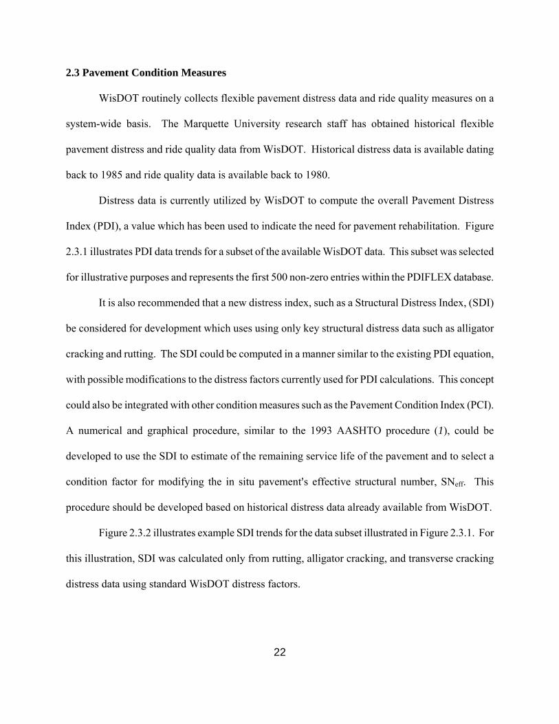
2.3 Pavement Condition Measures
WisDOT routinely collects flexible pavement distress data and ride quality measures on a
system-wide basis. The Marquette University research staff has obtained historical flexible
pavement distress and ride quality data from WisDOT. Historical distress data is available dating
back to 1985 and ride quality data is available back to 1980.
Distress data is currently utilized by WisDOT to compute the overall Pavement Distress
Index (PDI), a value which has been used to indicate the need for pavement rehabilitation. Figure
2.3.1 illustrates PDI data trends for a subset of the available WisDOT data. This subset was selected
for illustrative purposes and represents the first 500 non-zero entries within the PDIFLEX database.
It is also recommended that a new distress index, such as a Structural Distress Index, (SDI)
be considered for development which uses using only key structural distress data such as alligator
cracking and rutting. The SDI could be computed in a manner similar to the existing PDI equation,
with possible modifications to the distress factors currently used for PDI calculations. This concept
could also be integrated with other condition measures such as the Pavement Condition Index (PCI).
A numerical and graphical procedure, similar to the 1993 AASHTO procedure (1), could be
developed to use the SDI to estimate of the remaining service life of the pavement and to select a
condition factor for modifying the in situ pavement=s effective structural number, SNeff. This
procedure should be developed based on historical distress data already available from WisDOT.
Figure 2.3.2 illustrates example SDI trends for the data subset illustrated in Figure 2.3.1. For
this illustration, SDI was calculated only from rutting, alligator cracking, and transverse cracking
distress data using standard WisDOT distress factors.

Figure 2.3.1: PDI versus Age for WisDOT Performance Data
Figure 2.3.2: SDI versus Age for WisDOT Performance Data
PDI = 5.4933 x AgeR2 = 0.4699
0
10
20
30
40
50
60
70
80
90
100
0 5 10 15 20 25 30
Pavement Age, yrs
PD
I
SDI = 3.2464 x AgeR2 = 0.2598
0
10
20
30
40
50
60
70
80
90
100
0 5 10 15 20 25 30
Pavement Age, years
SD
I
24
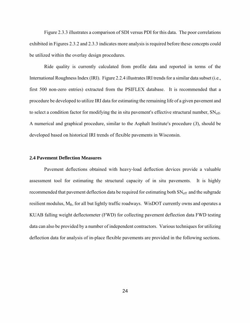
Figure 2.3.3 illustrates a comparison of SDI versus PDI for this data. The poor correlations
exhibited in Figures 2.3.2 and 2.3.3 indicates more analysis is required before these concepts could
be utilized within the overlay design procedures.
Ride quality is currently calculated from profile data and reported in terms of the
International Roughness Index (IRI). Figure 2.2.4 illustrates IRI trends for a similar data subset (i.e.,
first 500 non-zero entries) extracted from the PSIFLEX database. It is recommended that a
procedure be developed to utilize IRI data for estimating the remaining life of a given pavement and
to select a condition factor for modifying the in situ pavement=s effective structural number, SNeff.
A numerical and graphical procedure, similar to the Asphalt Institute=s procedure (3), should be
developed based on historical IRI trends of flexible pavements in Wisconsin.
2.4 Pavement Deflection Measures
Pavement deflections obtained with heavy-load deflection devices provide a valuable
assessment tool for estimating the structural capacity of in situ pavements. It is highly
recommended that pavement deflection data be required for estimating both SNeff and the subgrade
resilient modulus, MR, for all but lightly traffic roadways. WisDOT currently owns and operates a
KUAB falling weight deflectometer (FWD) for collecting pavement deflection data FWD testing
data can also be provided by a number of independent contractors. Various techniques for utilizing
deflection data for analysis of in-place flexible pavements are provided in the following sections.

Figure 2.3.3: SDI versus PDI Values
Figure 2.3.4: IRI versus Age for WisDOT Performance Data
SDI = 0.5946 x PDIR2 = 0.7133
0
10
20
30
40
50
60
70
80
90
100
0 20 40 60 80 100 120
PDI
SDI
IRI = 79.2 + 3.443 x AgeR2 = 0.2125
0
50
100
150
200
250
300
0 5 10 15 20 25 30 35
Pavement Age, years
IRI

26
A research factorial of pavement response data was generated to provide response data to test
the validity of available analysis procedures as well as to develop new equations, where appropriate.
The KENLAYER (5) computer program, which allows for stress-dependent base and subgrade layer
analyses, was utilized for this effort. Table 2.4.1 provides the range of pavement structures
investigated. A circular surface loading of 9,000 lb at 82.14 psi (radius = 5.9055 in) was applied in
all cases to represent a standard FWD loading. Surface deflections were calculated at offset
locations similar to those used during FWD testing.
Table 2.4.1 KENLAYER Pavement Factorial
Layer
Thickness Range
Modulus Range
HMA (8x8)
2" to 9 A (1" inc.)
Eac = 250 - 950 ksi (100 ksi inc.)
Aggregate Base (8x3)
6" - 15" (1" inc.)
MR = 4000 � .6 MR= 5000 � .5 MR = 8000 � �
Subgrade (1x4)
240"
ERI = 1 - 12.34 ksi
Bedrock
semi-infinite
E = 4,000 ksi
The complete factorial of KENLAYER runs included 7,680 separate pavement structures
(8x8x8x3x4) with base to HMA thickness ratios varying from 0.67 to 7.5. The output results were
parsed to include only those pavement structures where the ratio of base to HMA layer thickness
was in the range of 1.8 to 3.25, which is more in line with pavement design practices in Wisconsin,
resulting in a total of 2,592 separate pavement structures. The input SN of each pavement structure
was computed based on the input thickness and modulus values for each layer. The computed SN
values for the parsed factorial ranged from 2.09 to 6.73. These values, along with the surface

27
deflections generated by the program were used to test the validity of available models and to
developed improved equations, where warranted, to estimate key structural pavement parameters.
2.4.1 SNeff Predictions Based on AASHTO Equations
The deflection-based AASHTO equations (Eqns. 1.4 - 1.6) presented in Section 1.2.3 were
investigated to test their validity in predicting the input structural number used during the
KENLAYER factorial analysis. The three-step AASHTO process for estimating the in situ SNeff is
summarized as:
1. Estimate subgrade modulus based on surface deflections at all offset distances greater than 0, and consider the minimum computed modulus as the estimated in-place modulus.
2. Estimate Ep by iterative process based on total pavement thickness and estimated
subgrade modulus. 3. Estimate SNeff based on the estimated Ep and total pavement thickness using the
published AASHTO equation SNeff = 0.0045 Ep1/3T.
The above analysis process was applied to all pavement structures included in the parsed
KENLAYER output file. Figure 2.4.1 illustrates a comparison of estimated SNeff versus input SN
values based on this standard AASHTO process. As shown, SN values are consistently under-
predicted. When used in the context of an overlay design procedure based on structural deficiencies,
this under-estimation of SNeff would result in an increased overlay thickness requirement. Based on
standard HMA layer coefficients, the increased overlay thickness can be directly computed as:
HMAOL-inc = (Input SN - SNeff) / 0.44 Eq. 2.1
where: HMAOL-inc = increased HMA overlay thickness requirement, inches
Based on the data provided in Figure 2.4.1, the median increased overlay thickness is 2.7
inches (maximum = 3.9 inches).

Figuire 2.4.1: Effective SN versus Input SN Based on Current AASHTO Equation
0
1
2
3
4
5
6
7
2 3 4 5 6 7
Input SN
Estim
ated
SN
eff
29
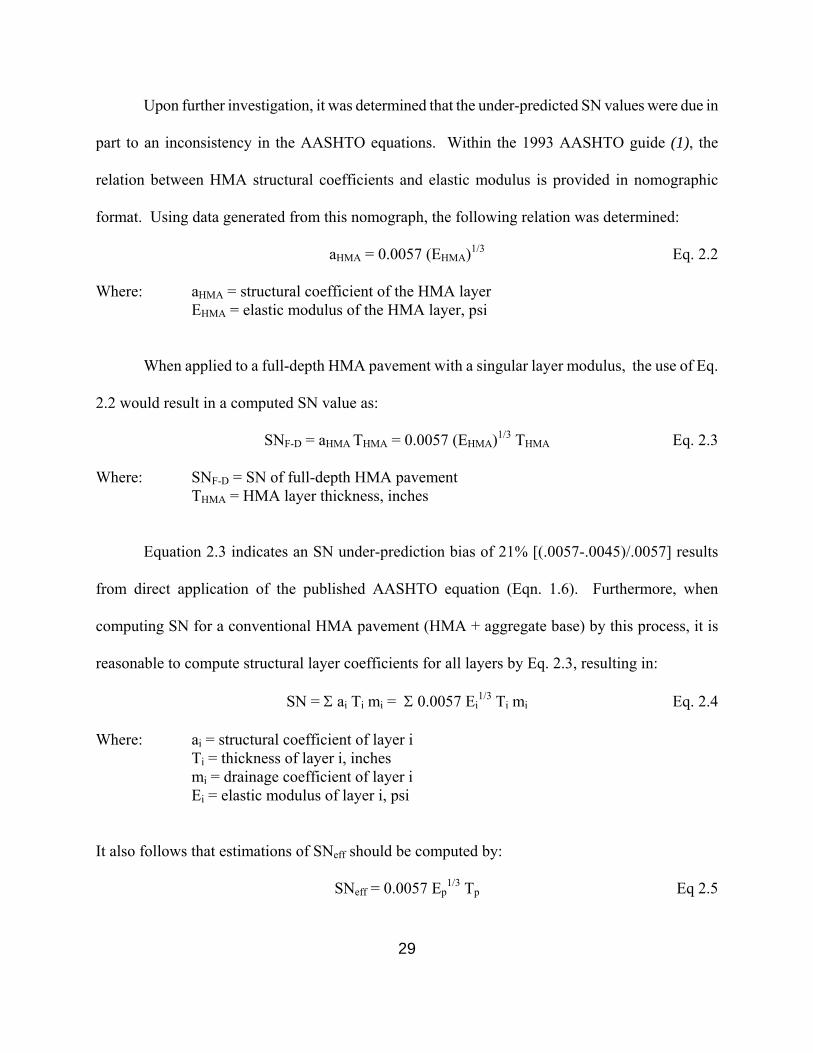
Upon further investigation, it was determined that the under-predicted SN values were due in
part to an inconsistency in the AASHTO equations. Within the 1993 AASHTO guide (1), the
relation between HMA structural coefficients and elastic modulus is provided in nomographic
format. Using data generated from this nomograph, the following relation was determined:
aHMA = 0.0057 (EHMA)1/3 Eq. 2.2
Where: aHMA = structural coefficient of the HMA layer EHMA = elastic modulus of the HMA layer, psi
When applied to a full-depth HMA pavement with a singular layer modulus, the use of Eq.
2.2 would result in a computed SN value as:
SNF-D = aHMA THMA = 0.0057 (EHMA)1/3 THMA Eq. 2.3
Where: SNF-D = SN of full-depth HMA pavement THMA = HMA layer thickness, inches
Equation 2.3 indicates an SN under-prediction bias of 21% [(.0057-.0045)/.0057] results
from direct application of the published AASHTO equation (Eqn. 1.6). Furthermore, when
computing SN for a conventional HMA pavement (HMA + aggregate base) by this process, it is
reasonable to compute structural layer coefficients for all layers by Eq. 2.3, resulting in:
SN = Σ ai Ti mi = Σ 0.0057 Ei1/3 Ti mi Eq. 2.4
Where: ai = structural coefficient of layer i Ti = thickness of layer i, inches mi = drainage coefficient of layer i Ei = elastic modulus of layer i, psi
It also follows that estimations of SNeff should be computed by:
SNeff = 0.0057 Ep1/3 Tp Eq 2.5

30
where: SNeff = effective structural number of the in-place pavement Ep = equivalent modulus of the in-place pavement Tp = total pavement thickness above subgrade, inches
Effective structural numbers for each pavement structure were computed using these revised
equations. Figure 2.4.2 provides predicted (Eq. 2.5) versus actual (Eq. 2.4) SN values for this same
data set. As shown, SN values are still consistently under-predicted, resulting in a median increased
overlay thickness requirement of 1.6 inches (maximum = 2.4 inches).
Based on a regression analysis of the parsed KENLAYER data, better agreement is achieved
using a modified form of the SNeff equation as:
SNeff = 1.055 + 0.0051 Ep1/3 T R2 = 0.9805 Eq. 2.6
Figure 2.4.3 provides predicted (Eq. 2.6) versus actual (Eq. 2.4) SN values. As shown, the
SN under-prediction bias is eliminated and the maximum increased overlay thickness requirement is
reduced to +/- 0.9 inches, with 89% of the errors less than +/- 0.5 inches. While this represents a
marked reduction in overlay thickness errors resulting from SNeff predictions, further attempts were
made to find alternate deflection-based strategies which may further reduce the associated overlay
thickness error.
2.4.2 SNeff Predictions Based on Deflection Algorithms
Previous research (5,6) has shown that the subgrade modulus and pavement flexural rigidity
can be directly back-calculated from deflection data. Thompson (5) provides the following equation
for estimating the breakpoint resilient modulus of the subgrade:
Eri = 26.45 - 5.12 D36 + 0.2586 D362 Eq. 2.7
where: Eri = subgrade breakpoint resilient modulus, ksi D36 = surface deflection at 36 inches from load, mils @ 9,000 lb
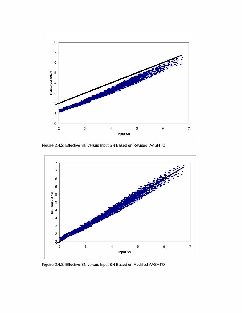
Figuire 2.4.2: Effective SN versus Input SN Based on Revised AASHTO
Figuire 2.4.3: Effective SN versus Input SN Based on Modified AASHTO
0
1
2
3
4
5
6
7
8
2 3 4 5 6 7Input SN
Estim
ated
SN
eff
2
3
3
4
4
5
5
6
6
7
7
2 3 4 5 6 7Input SN
Estim
ated
SN
eff

32
The backcalculated Eri values determined by Eq., 2.7 are reported to provide reasonable
estimates of the design MR value which is required for new pavement design within the AASHTO
process.
Thompson (5) also introduced an additional deflection term known as the Area Under the
Pavement Profile, AUPP. AUPP is simply calculated from multi-sensor deflection data commonly
obtained during FWD testing using the equation:
AUPP = 2 ( 5 D0 - 2 D12 - 2 D24 - D36) Eq. 2.8
where: AUPP = Area Under the Pavement Profile Di = surface deflection at i inches from the center of
loading, mils @ 9,000 lb
Preliminary models for estimating ET3 and SNeff from AUPP (Eq. 2.8) and Eri (Eq. 2.7) were
developed by Maguire (6):
Log ET3 = 6.21 - 0.49 Log AUPP + 0.0023 Log Eri Eq. 2.9
SNeff = 0.1477 (ET3)1/3 - 0.014 Eri - 6.43 Eq. 2.10
where: ET3 = flexural rigidity of entire pavement system, kip-inches
Equations 2.9 and 2.10 were developed based on a limited factorial analysis of flexible
pavement response using stress-dependent elastic layer computer modeling. It is important to note
that pavement layer thicknesses, commonly obtained by coring, are not required for the deflection
analysis using these equations.

33
Figure 2.4.4 illustrates a comparison of predicted versus actual SN values using the
preliminary models applied to the parsed output results from the KENLAYER factorial analysis. As
shown, the preliminary equations result in a consistent under-prediction of the SNeff values, which
correlates to a median increased overlay thickness requirement of 2.0 inches (maximum = 4.1
inches).
Using regression analysis on the larger parsed KENLAYER output file, revised predictive
equations were developed during this research. These equations, which should be applied
sequentially, are as follows:
eEri = 22.04 - 3.645 D36 + 0.158 D362 R2 = 0.9188 Eq. 2.11
Log eE1/3T = 3.574 - 0.437 Log AUPP - 0.066 Log eEri R2=0.9045 Eq. 2.12
SNeff = 0.0055 eE1/3T - 0.0012 eEri + 0.144 R2=0.9058 Eq. 2.13
Where: eEri = estimated breakpoint subgrade resilient modulus, ksi D36 = surface deflection at 36 inches from the center of loading, mils@9k
eE1/3T = estimated overall pavement flexural rigidity term, lb-in1/3
Figure 2.4.5 illustrates predicted versus input SN values resulting from the application of the
revised equations. As shown, the predicted SN values are unbiased and clustered along the line of
equality. However, the scatter in the predicted SN values correlates to an overall range in the
overlay thickness estimation error of approximately +/- 1.9 inches, with 84% of the values within +/-
1.0 inches and 49% within +/-0.5 inches. While equations such as these offer the benefit of not
having to obtain in situ pavement layer thicknesses from coring, the associated overlay estimation
errors may render them impractical to apply.

Figuire 2.4.4: Effective SN versus Input SN Based on Preliminary Eri-AUPP
Figuire 2.4.5: Effective SN versus Input SN Based on Modified Eri-AUPP
0
1
2
3
4
5
6
7
8
2 3 4 5 6 7
Input SN
Estim
ated
SN
ef
2
3
4
5
6
7
2 3 4 5 6 7
Input SN
Estim
ated
SN
eff

35
2.4.3 SNeff Predictions Based on Asphalt Institute Procedures
The Asphalt Institute (AI) deflection-based analysis procedures presented in Section 1.2.6
were further investigated to determine if applicable analysis strategies could be developed for
predicting SNeff without knowledge of in-place pavement thickness. As developed, the AI
procedures estimate allowable ESALs based only on maximum surface deflection. Knowledge of
the subgrade modulus, which significantly contributes to overall pavement deflection, is necessary to
provide estimates of the SNeff.
Based on a regression analysis of the parsed KENLAYER data, the best models for
estimating SNeff from only maximum deflection and subgrade modulus are:
THMA > 2 inches: SNeff = 17.4 - 0.263 Esg - 7.56 Log D0 R2 = 0.881 Eq. 2.14
THMA = 2 inches: SNeff = 5.2 - 0.074 Esg - 1.44 Log D0 R2 = 0.547 Eq. 2.15
Where: Esg = Minimum subgrade modulus computed by AASHTO (Eq. 1.4), ksi D0 = Maximum deflection, mils at 9,000 lb
Figure 2.4.6 provides an illustration of the predicted versus actual SN values determined by
the above equations. As shown, the data are clustered along the line of equality but the range of
errors for the required overlay thickness is approximately +/- 2 inches, with 81% of the values less
than +/- 1 inch and 49% less than +/- 0.5 inches. These errors are very similar to those associated
with the Eri-AUPP approach and again may be considered excessive for practical applications.

Figuire 2.4.6: Effective SN versus Input SN Based on AI
2
3
3
4
4
5
5
6
6
7
7
2 3 4 5 6 7
Input SN
Estim
ated
SN
eff

37
2.4.4 Combined Overlay Design Approach
An overlay design approach which combines aspects of both the AASHTO and AI analysis
procedures was investigated to determine if practical guidelines could be established. Using the data
from the parsed KENLAYER analysis, the allowable ESALs for each pavement system were
computed following current AASHTO and AI procedures. While the AI procedure computes
allowable ESALs based solely on maximum deflection, the current AASHTO procedures require
inputs of subgrade modulus, pavement structural number, terminal serviceability, and design
reliability. It is recognized that the current WisDOT design procedures do not require inputs of
design reliability; however, it was deemed appropriate to include this factor to expand the
applicability of the results.
During the AASHTO analysis, deflection data contained in the parsed KENLAYER results
were first used to estimate the field subgrade modulus using AASHTO procedures (Eq. 1.4).
Allowable ESALs were then computed based on the input SN and arbitrary selections of design
reliability and terminal serviceability. The calculated allowable ESALs were then plotted against
maximum surface deflection to examine the appropriateness of the current AI relation. Figure 2.4.7
illustrates an example plot based on AASHTO allowable ESALs computed using a design reliability
of 90% and a terminal serviceability of 2.5 (ΔPSI = 1.7). Also shown are data trend lines based on the
AASHTO data and the AI equation, which can be seen to be in general agreement for this data set.
However, changes to inputs values of design reliability and/or terminal serviceability can result in
significant discrepancies between the AASHTO and AI results, as shown in Figure 2.4.8 which was
developed based on a design reliability of 50% and a terminal serviceability of 2.0 (ΔPSI = 2.2).

Figuire 2.4.7: Allowable ESALs versus Maximum Deflection
Figuire 2.4.8: Allowable ESALs versus Maximum Deflection
AASHTO: ESAL = 0.1386Do-4.7504
R=90%, ∆psi=1.7
AI: ESAL = 1.1575D0-4.1017
1.E+02
1.E+03
1.E+04
1.E+05
1.E+06
1.E+07
1.E+08
1.E+09
0.01 0.1 1
Maximum Deflection, inches @ 9k
Allo
wab
le E
SA
Ls
AASHTO: ESAL = 0.3101Do-5.0081
R=50%, ∆psi=2.2
AI: ESAL = 1.1575D0-4.1017
1.E+02
1.E+03
1.E+04
1.E+05
1.E+06
1.E+07
1.E+08
1.E+09
1.E+10
0.01 0.1 1
Maximum Deflection, inches @ 9k
Allo
wab
le E
SA
Ls

39
Based on an analysis of AASHTO allowable ESALs computed for a range of design
reliability and terminal serviceability values, the following general model form was consistently
applicable for estimating allowable ESALs from maximum deflection, D0:
Allowable ESALs = A D0B Eq 2.16
Table 2.4.2 provides specific coefficients and exponents for varying levels of design
reliability and terminal serviceability. The use of Equation 2.16 with appropriate terms selected
from Table 2.4.2 allows for a direct analysis of the allowable ESALs based on maximum deflection
only.
Table 2.4.2 Coefficients and Exponents for Equation 2.16
Reliability
%
Terminal
Serviceability
A
B
Terminal
Serviceability
A
B
50
2.5
0.5232
-4.7504
2.0
0.3101
-5.0081
75
2.5
0.2602
-4.7504
2.0
0.1542
-5.0081
85
2.5
0.1786
-4.7504
2.0
0.1059
-5.0081
90
2.5
0.1386
-4.7504
2.0
0.0821
-5.0081
95
2.5
0.0951
-4.7504
2.0
0.0564
-5.0081
99
2.5
0.0469
-4.7504
2.0
0.0278
-5.0081
A secondary analysis was completed which utilized the allowable ESALs computed by the
AI equation to compute a related SNeff value based on AASHTO criteria. During this analysis, the
in-place subgrade modulus was estimated based on the AASHTO equation and inputs for design
reliability and terminal serviceability were set to 90% and 2.5, respectively. The SNeff of the
pavement was varied until agreement was reached between calculated AI and AASHTO ESALs.
40
Figure 2.4.9 provides a comparison equivalent AI SN values versus input SN values. As shown, the
equivalent AI SN values tends to under-estimate the SN values as input SN values increase.
The equivalent AI SN values were also compared to input SN values to determine the impact
on overlay thickness requirements. Figure 2.4.10 provides a plot of the associated overlay thickness
estimation error versus the input pavement structural number, with positive values indicating a
thicker overlay would be required due to an under-prediction of the input SN (SNeff < SNinput), and
vice versa. As shown, the overlay thickness estimation error tends to increase as the input structural
number increases. Furthermore, the overlay thickness estimation error ranges from -1.5 inches to
+2.8 inches, with only 57% of the values within +/- 1.0 inches. making this method impractical.
2.4.5 Preferred Deflection-Based Methods
To maintain consistency with the current WisDOT flexible pavement design procedures
which are based on the SN concept, the analysis results presented in the previous sections indicate
the preferred deflection-based method which provides the best estimate of SNeff for in-place HMA
pavements is the modified AASHTO method. Based on the results of the factorial analysis, this
method provided estimations of SNeff values which were within 5% of the input values for 85% of
the pavement structures investigated, as illustrated in Figures 2.4.11 and 2.4.12. Furthermore,
application of this method is projected to provide overlay thickness requirements which are within
+/- 0.9 inches of those required based on perfect assessment of SNeff, with 90% of the values being
within +/- 0.5 inches, as illustrated in Figures 2.4.13 and 2.4.14. This appears to be the practical
limit of deflection-based approaches for developing overlay thickness requirements based on the
structural deficiency approach.

Figuire 2.4.9: Effective SN Based on AI Analysis versus Input SN
Figuire 2.4.10: Overlay Thickness Estimation Error Based on AI Analysis versus Input SN
2
3
4
5
6
7
2 3 4 5 6 7Input SN Value
Equi
vale
nt S
N B
ased
on
AI A
naly
sis
-2.0
-1.0
0.0
1.0
2.0
3.0
4.0
2 3 4 5 6 7
Input SN Value
Ove
rlay
Thic
knes
s Er
ror (
AI),
inch
es

Figuire 2.4.11: SNeff Estimation Errors Based on Modified AASHTO
Figuire 2.4.12: SNeff Estimation Errors Based on Modified AASHTO
0
10
20
30
40
50
60
70
80
90
100
-10 -5 0 5 10 15 20SNeff Estimation Error, %
Cum
ulat
ive
Freq
uenc
y, %
-10
-5
0
5
10
15
20
2 3 4 5 6 7
Input SN
SNef
f Est
imat
ion
Erro
r, %

Figuire 2.4.13: Overlay Thickness Estimation Errors Based on Modified AASHTO
Figuire 2.4.14: Overlay Thickness Estimation Errors Based on Modified AASHTO
0102030405060708090
100
-1 -0.5 0 0.5 1Overlay Thickness Estimation Error, inches
Cum
ulat
ive
Freq
uenc
y, %
-1.0
-0.5
0.0
0.5
1.0
2 3 4 5 6 7Input SN
Ove
rlay
Thic
knes
s Es
timat
ion
Erro
r, in
ches

44
The preferred deflection-based analysis method is summarized by the following steps:
1. Surface deflections at all sensor locations outside the center of loading are used to estimate the field subgrade modulus by Eq. 1.4.
2. The effective pavement modulus is estimated by an iterative process using the previously
estimated subgrade modulus (Step 1), measured load and maximum deflection, and known total pavement thickness by Eq 1.5.
3. The effective SN of the pavement is estimated based on the previously estimated effective
pavement modulus (Step 2) and known total pavement thickness by Eq 2.6.
This modified AASHTO deflection-based analysis method is somewhat cumbersome to
apply and requires the use of iterative analysis in Step 2. This can be accomplished manually or
with goal seeking functions available in current spreadsheet programs. Additionally, accurate
measures of the total in-place pavement thickness are required to obtain reasonable estimates of the
in situ SNeff. While these measures can be readily obtained by selective pavement coring, variations
in pavement layer thicknesses along a given project may invalidate many deflection test results
where cores are not obtained and total pavement thickness must be estimated.
To illustrate the impacts of pavement thickness on the modified AASHTO approach, the
parsed data set was re-analyzed using adjusted total pavement thicknesses equal to 90% of the actual
input values. Figures 2.4.15 and 2.4.16 illustrate the impacts of associated pavement thickness
errors on estimated SNeff and overlay thickness requirements. As shown, SNeff tends to be
increasingly under-predicted as the input SN increases and the percentage of estimated overlay
thickness errors less than +/- 0.5 inches drops to approximately 54%, which is essentially equal to
results obtained with alternative methods which do not require pavement thickness as an input.

Figuire 2.4.15: SN Estimation Errors Based on Modified AASHTO with Decreased Thickness
Figuire 2.4.16: Overlay Thickness Errors Based on Modified AASHTO with Decreased Thickness
2
3
4
5
6
7
2 3 4 5 6 7
Input SN
Estim
ated
SN
eff
0
10
20
30
40
50
60
70
80
90
100
-1 -0.5 0 0.5 1 1.5 2
Overlay Thickness Estimation Error, inches
Cum
ulat
ive
Freq
uenc
y, %

46
Considering the implications of pavement thickness errors within the preferred AASHTO
approach, it appears reasonable to consider the Eri-AUPP analysis method as a practical alternative
to the modified AASHTO approach. While this method introduces greater error, the removal of
pavement coring requirements may offset this deficiency. Based on the results of the factorial
analysis, this method provided estimations of SNeff values which were within 10% of the input
values for 77% of the pavement structures investigated as illustrated in Figures 2.4.17 and 2.4.18.
Furthermore, this method is projected to have associated overlay thickness errors of less than +/- 1.0
inches 84% of the time, with errors within +/- 0.5 inches occurring for 49% of the trials, as
illustrated in Figures 2.4.19 and 2.4.20.
The Eri-AUPP analysis method is summarized as follows:
1. Surface deflections obtained at 36 inches from the center of loading are used to estimate the breakpoint subgrade resilient modulus, Eri by Eq 2.11.
2. Surface deflections measured at 0, 12, 24 and 36 inches from the center of loading are used
to compute the Area Under the Pavement Profile, AUPP by Eq 2.8. 3. The pavement flexural rigidity term E1/3T is estimated based on the previously estimated Eri
(Step 1) and calculated AUPP by Eq 2.12. 4. The estimated SNeff is determined based on the estimated Eri and E1/3T values by Eq 2.13.
The Eri-AUPP analysis is relatively simple to apply and can be easily implemented in
spreadsheet format. Because no pavement coring is required in this method, the process offers an
attractive alternative to the modified AASHTO method.
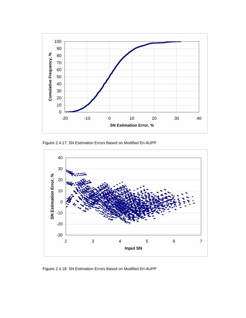
Figuire 2.4.17: SN Estimation Errors Based on Modified Eri-AUPP
Figuire 2.4.18: SN Estimation Errors Based on Modified Eri-AUPP
0102030405060708090
100
-20 -10 0 10 20 30 40SN Estimation Error, %
Cum
ulat
ive
Freq
uenc
y, %
-30
-20
-10
0
10
20
30
40
2 3 4 5 6 7
Input SN
SN E
stim
atio
n Er
ror,
%

Figuire 2.4.19: Overlay Thickness Errors Based on Modified Eri-AUPP
Figuire 2.4.20: Overlay Thickness Errors Based on Modified Eri-AUPP
0102030405060708090
100
-2 -1.5 -1 -0.5 0 0.5 1 1.5 2 2.5Overlay Thickness Estimation Error, inches
Cum
ulat
ive
Freq
uenc
y, %
-2
-1.5
-1
-0.5
0
0.5
1
1.5
2
2.5
2 3 4 5 6 7
Input SN
Ove
rlay
Thic
knes
s Es
timat
ion
Erro
r, in
ches

49
CHAPTER 3 OVERLAY DESIGN CONSIDERATIONS
3.1 Introduction
The current WisDOT flexible pavement design procedures published in Procedure 14-10-5 of
the Facilities Development Manual (FDM) provide for the determination of the required SN for a
new pavement based on provided soils and traffic data. FDM Procedure 14-10-30 provides little
guidance for the design of a structural HMA overlay over an existing flexible pavement. Guidelines
44.15 and 44.20 of the Highway Maintenance Manual provide criteria for the selection of candidate
projects for maintenance overlays. These overlays are limited to a maximum thickness of 2.5 inches
and have an expected service life of 2 – 18 years depending on existing pavement condition and
repair process.
The overlay design procedures developed during this research represent an extension to
current maintenance policies, allowing the designer to target HMA overlay thickness to the
structural capacity of the existing flexible pavement as defined by its effective structural number,
SNeff. Within this context, maximum overlay thickness requirements resulting from the application
of these procedures are not constrained. Furthermore, overlays may be designed by these procedures
to serve any desired service life; however a practical maximum of 20 years may be considered
appropriate for the AASHTO based structural deficiency approach.
It is recognized that the design of structural overlays based on surface deflections and
pavement coring may not be economically justifiable for all pavements. For lightly trafficked
pavements with design ESAL values less than 1 million, structural overlay thickness requirements
may be developed based on surface distress evident within the existing pavement. It is

50
recommended that the guidelines provided by AASHTO and presented in Table 1.2.2 be utilized to
estimate the SNeff for these pavements.
For heavier trafficked roadways with design ESAL values greater than 1 million, it is
recommended that the deflection-based procedures presented in Section 2.4.5 of this report be used
to establish the SNeff of the in-place pavement and ultimately the overlay thickness requirement
based on the structural deficiency approach. This approach is summarized by the following:
TOL = (SNnew - SNeff) / 0.44 Eq. 3.1
Where: TOL = overlay thickness, inches SNnew = Required SN for a new flexible pavement based on current WisDOT
design procedures SNeff = effective SN of the in situ pavement determined from procedures
presented in Section 2.4.5
The SNeff analysis procedures presented in Section 2.4.5 provide guidance on the analysis of
collected deflection data with or without coring data. During initial implementations, it is
recommended that comparative overlay thickness design be developed using both analysis paths
(with and without coring data). The following provides further information relating to the conduct
of the deflection testing program which is integral to each analysis method.
3.2 Deflection Testing Procedures
For use in the overlay design process, deflection testing should be conducted with a falling
weight deflectometer (FWD). The FWD has been shown to provide data which closely simulates
the effects of moving wheel loads and is considered the current state-of-practice for deflection
testing. WisDOT currently owns and operates an FWD and numerous private agencies also
own/operate equipment of this type and can provide data collection services as needed. The major

51
drawback to the use of the FWD is its requirement for traffic control during testing which can
significantly increase project costs. High-speed deflection test equipment is currently under
development to eliminate this need for traffic control, but at the time of this report it is too soon to
know if data collected by these devices will be directly transferable.
Test loads of approximately 9,000 lbs are recommended to provide data which simulates the
action of a standard 18,000 single axle load. At least one 9,000 lb seating load should be applied at
each test location prior to data collection. Deflection testing should be conducted along the outer
wheel path to obtain representative data from this critical pavement area. Test spacings should be
selected at 100 - 250 ft intervals to provide sufficient data to characterize the variations in pavement
quality along the entire project length, with a minimum of 10 deflection tests collected from any
given project. Deflection testing may conducted in sound (uncracked) and unsound locations. As a
general rule, deflections should not be collected within six feet of isolated transverse cracks.
Deflections may be obtained in areas of fatigue cracking; however these locations should be
identified such that the effects on SNeff may be considered during the overlay thickness analysis.
Deflection testing should be conducted during warmer periods when there is no chance of
frost or frozen layers within the pavement structure. Pavement temperatures should be recorded
during testing and used to adjust the maximum measured deflection to a reference pavement
temperature of 68oF. It is recommended that direct measurement of the mid-depth HMA pavement
temperatures be made during testing. Procedures for correcting maximum deflection to the reference
temperature of 68oF (20oC) are provided by FHWA (8). Figure 3.2.1 provides a figure extracted
from this report which illustrates the temperature correction factor as a function of HMA thickness.

52
Figure 3.2.1 Maximum Deflection Temperature Adjustment Factor (from FHWA-RD-98-085)

53
3.3 Project Analysis
The deflection-based analysis procedures presented in section 2.4.5 should be applied to the
data from each test location to establish a profile of structural overlay thickness requirements along
the entire project limits. Examination of this profile may indicate that sub-sectioning is warranted,
with variable overlay thickness requirements established within each subsection. Whether or not
sub-sectioning is warranted, a statistical analysis of overlay thickness requirements should be
conducted to establish the mean and standard deviation for each design section. These values may
then be utilized to develop reliability-based overlay thickness designs.
It should be noted that any outliers in the data set, resulting from atypical overlay thickness
requirements for unusually weak or strong pavement locations, should be considered for exclusion
prior to the calculation of the section mean and standard deviation, especially for smaller data sets.
Unusually strong pavement outliers will result in a reduced mean and an increased standard
deviation, with the magnitude of the change dependent on sample size. Depending on the level of
design reliability selected, these changes could result in a decreased or increased overlay thickness
requirement. For example, consider a small data set of 10 test locations with location-specific
overlay thickness requirements of 3.5, 3.7, 3.5, 4.0, 3.9, 4.2, 3.6, 4.0, 4.2, 2.0 inches. For this data
set, one may consider the 2.0 inch overlay thickness as an outlier due to a strong pavement location.
Including this outlier results in a mean overlay thickness requirement of 3.66 inches and a standard
deviation of 0.640 inches while excluding the outlier results in a mean overlay thickness requirement
of 3.84 inches and a standard deviation of 0.279 inches. For a design reliability of 50%, setting the
overlay thickness requirement equal to the mean value obviously results in a reduced requirement if
the strong outlier is included in the calculations (3.66 vs 3.84 inch design overlay). If, however, the
54
design reliability is increased to 68% (mean + 1 standard deviation), the data set including the outlier
would result in a design overlay thickness of 4.30 inches compared to 4.12 inches if the outlier was
excluded. While this is a simplified example, it serves to highlight the unexpected impacts of
outliers.
Unusually weak pavement locations should also be considered for exclusion during the
selection of overlay thickness requirements if it is anticipated that these locations will be repaired by
base patching prior to overlay. However, if no pre-overlay repairs are considered then it may be
logical to include the outlier in the statistical analysis. It may also be warranted to conduct an
economic analysis of overlay requirements and associated costs both with and without the pre-
overlay repair of weakened sections to establish the most cost-effective overlay design scenario.

55
CHAPTER 4 FINDINGS AND RECOMMENDATIONS
This report presents the results of a review of published procedures for the design of HMA
overlays of existing flexible pavements. Overlay design procedures utilized by surrounding States
were also examined and summarized. Based on these reviews, a number of key data elements have
been identified for consideration within the proposed WisDOT overlay design procedures for
flexible pavements, including surface distress, ride quality, and pavement deflections.
The overlay design procedures developed as part of this research are appropriate for the
design of structural HMA overlays which are intended to significantly increase the load-carrying
capacity of existing flexible pavements. These procedures are intended to extend the current options
available to designers as published within the WisDOT Facilities Development Manual (FDM) and
the Highway Maintenance Manual (HMM).
4.1 Summary of Findings
The analyses conducted as part of this research resulted in the following findings:
(1) The design of structural HMA overlays of existing flexible pavements can be integrated
within current WisDOT procedure for the design of new flexible pavements by utilizing the
structural deficiency approach. This process establishes the required overlay thickness based on the
difference between the effective structural number, SNeff, of the existing pavement existing and the
structural number required for a new flexible pavement design.
(2) The SNeff of existing flexible pavements can be established based on deflections,
distress, or ride quality. The use of deflection data is considered appropriate for pavements with

56
design traffic loadings in excess of 1 million ESALs. For lightly trafficked pavements the SNeff may
be developed without the use of deflection data. The accuracy of SNeff estimations can be improved
by including pavement layer thickness data obtained through selective coring; however, all analysis
techniques have associated errors.
(3) Modified deflection-based SNeff analysis procedures were developed based techniques
presented in the 1993 AASHTO Guide for the Design of Pavement Structures. These procedures
provided the best correlations between SNeff and input SN using deflection data generated during
computer modeling of a large pavement factorial. These procedures are somewhat cumbersome to
apply and are best suited for analysis when pavement layer thicknesses are known. Based on the
results presented, these procedures were shown to provide overlay thickness recommendations
which were within ½ inch of “truth”, as represented by exact component analysis of the pavement
structures investigated during computer modeling, for 90% of the structures investigated.
(4) Alternative deflection-based analysis techniques developed as part of this research were
also shown to provide reasonable correlations between SNeff and input SN using deflection data
generated during computer modeling of the large pavement factorial. These procedures are easier to
apply and do not require knowledge of the in-place pavement layer thicknesses. Based on the results
presented, these procedures were shown to provide overlay thickness recommendations which were
within ½ inch of “truth” for 40% of the pavement structures investigated and within 1 inch of truth
for 84% of the structures. These values were shown to be comparable to the modified AASHTO
approach if the assumed pavement thickness is in error by 10%.

57
4.2 Recommendations
Based on the findings from this research, it is recommended that the structural deficiency
approach be implemented for the design of structural HMA overlay thickness requirements for
existing flexible pavements. The procedures presented in this report are considered appropriate for
establishing thickness requirement for structural HMA overlays. Thickness requirements resulting
from the application of these methods are not intended to supersede minimum/maximum HMA layer
thickness guidelines as detailed in the WisDOT Standard Specifications, Section 460.3.2.
The structural deficiency approach utilizes both the effective structural number, SNeff, of the
existing pavement and the structural number required for new design. It is recommended that the
deflection-based analysis procedures presented in Section 2.4.5 of this report be promoted to
estimate the effective structural number, SNeff, of the existing flexible pavement that are projected to
carry at least 1 million ESALs after overlay. During initial implementations, both the modified
AASHTO and revised AUPP-Eri should be utilized to establish SNeff and asses the impacts of
analyses with and without available coring data.
For lightly trafficked pavements with less than 1 million design ESALs, it is recommended
that the SNeff be established based on the deflection based-analysis techniques or a component
analysis based on layer thickness and existing pavement distress. The guidelines presented by
AASHTO for the selection of structural layer coefficients based on existing distress are
recommended for use when deflection data is unavailable and the component analysis is selected.
The recommended overlay thickness design procedures are compatible with the current
WisDOT procedures for the design of new flexible pavements, as published within Procedure 14-10-
5 of the Facilities Development Manual (FDM). When deflection data are utilized, the field

58
subgrade modulus is determined directly from deflections. This value may require seasonal
adjustments depending on the time of deflection testing as well as conversion to a representative soil
support value following standard WisDOT procedures.
The overlay design procedures presented in this report may be utilized to develop thickness
requirements for any user-supplied design life. The practical limitation for these procedures is a 20-
year design life which is consistent with the maximum design life currently assumed for the design
of traditional HMA pavements in Wisconsin following FDM Procedure 14-10-5. Shorter design
lives can be considered by developing new pavement SN requirements using projected traffic levels
within the 1972 AASHTO equation currently used by WisDOT.

59
5.0 REFERENCES
1. AASHTO Guide for Design of Pavement Structures, American Association of State
Highway and Transportation Officials, 1993. 2. Pavement Design for Roads, Streets, Walks, and Open Storage Areas, Army TM 5-822-5,
Air Force AFM 88-7, Chap.1, Departments of the Army and the Air force, June, 1992. 3. Asphalt Overlays for Highway and Street Rehabilitation, The Asphalt Institute, 1983. 4. AASHTO Guide for Design of Pavement Structures, American Association of State
Highway and Transportation Officials, 1986. 5. KENLAYER Pavement Analysis and Design Software, Y.H. Huang, Prentice Hall, 1993. 6. Hot Mix Asphalt Overlay Design Concepts for Rubblized Portland Cement Concrete
Pavements, M.R. Thompson, Transportation Research Record No. 1684, Transportation Research Board, Washington, D.C., 1999.
7. Development of a Deflection-Based Algorithm for Estimating In Situ Structural Capacity
of HMA Pavement Systems, J.P. Maguire, Master=s Essay, Marquette University, August 1999.
8. Temperature Predictions and Adjustment Factors for Asphalt Pavement, Publication No.
FHWA-RD-98-085, June 2000.