Embed Size (px)
Citation preview
Development of PMMA-Precoating Metal Prostheses via InjectionMolding: Residual Stresses
Wenping Zhao,1 Stephan Barsun,1 Karthik Ramani,1 Todd Johnson,2 Richard King,2 Steve Lin2
1 Composites and Polymer Processing Laboratory (CPPL), School of Mechanical Engineering, Purdue University,West Lafayette, Indiana 47907-1288
2 Zimmer, Inc., Warsaw, Indiana 46581
Received 9 September 2000; revised 15 December 2000; accepted 10 January 2001Published online XX Month 2001
Abstract: Injection molding polymethylmethacrylate (PMMA ) was developed as apotentialmetal prosthesis precoating method for surgical implantation. However, residual stressesgenerated in the injection-molded PMM A affect the mechanical performance of the coatingpolymer. This study used plane polariscope testing to demonstrate the residual stress distri-bution in the injection-molded polymer. Slittin g and strain gages were combined with finiteelement analysis to give a quantitativ e measure of the residual stresses. The residual stresstesting indicated that the highest circumferential residual stress in the injection-moldedPMM A was '5 MPa in tension. Two methods, water soaking and slitting, were developed forreducing residual stresses. A series of four surgical implantation simulation processes weredesigned. The two methods for reducing residual stress were used in the simulations. © 2001John Wiley & Sons, Inc. J Biomed Mater Res (Appl Biomater) 58: 456–462, 2001
Keywords: residual stress; polariscope; strain gage; FEA; implantation
INTRODUCTION
Polymethylmethacrylate (PMMA) is used as a cement be-tween an implant and bone. Traditionally the use of PMMAinvolves manual mixing of liquid and powder. The mixingresults in air entrapment, creating pores.1 Several attemptshave been made to improve the mechanical properties of thePMMA cement layer, including the recent attempts to useinjection molding to apply PMMA coating on themetal insertprior to surgical implantation.2,3 Creation of premanufacturedPMMA coating is intended to improve the metal–cementinterface as well as the implant seating into bone. By elimi-nating thepores in cement, injection molding isalso aimed toincrease the mechanical performance of the cement layer.
In Moriarty and Ramani’sstudy, aPMMA injection mold-ing process was investigated.3 However, the present studydemonstrated that the residual stresses in the PMMA ringdeveloped during the injection molding process were signif-icant and could cause cracks of the PMMA during implanta-tion. In this study, a slitting technique combined with finiteelement analysiswasdeveloped to test the residual stresses inthe PMMA ring. Two methods, water soaking and slitting ofthe PMMA ring, were developed to reduce the residualstresses.
Because the metal prostheses precoated with PMMA areto be implanted into human bodiesusing PMMA cement, it isimportant to examine the interface performance of the injec-tion-molded PMMA/cemented PMMA. In this study, wedeveloped a cementing process to simulate surgical implan-tation. A ring shearing test was used to characterize theinterface strength. The two methods for reducing residualstress were used in the surgical implantation simulation.
INJECTION MOLDING
The injection-molded specimen is illustrated in Figure 1. Thethickness of the injection-molded PMMA coating is 5.0 mm.CP-1000 impact grade (IG) PMMA from ICI Plastics is usedin this study. The metal insert is Bio-Dur™ Carpenter CCMtcobalt chromium molybdenum (CoCr) alloy. The CoCr sur-face is a smooth and warm worked surface and its surfaceroughness is 0.82 mm. Table I shows the basic mechanicaland thermal properties of the materials. Processing tempera-ture and pressure, packing/holding time and pressure, andcooling time were all considered in the injection moldingprocess development. Table II lists the injection moldingprocess parameters,3 which were used in this study.
RESIDUAL STRESS TESTING
A plane polariscope was used to demonstrate the residualstress distribution in the injection-molded PMMA ring. For a
Correspondence to: Karthik Ramani, Composites and Polymer Processing Labo-ratory (CPPL), School of Mechanical Engineering, Purdue University, West Lafayette,IN 47907–1288
Contract grant sponsor: Zimmer, Inc.
456
quantitative measurement of the residual stresses, a techniquecombining radial slitting and strain gages was developed. Afinite element model was developed to analyze the strain gagemeasurements. The finite element analysis also provided in-sight into the injection-molded PMMA-metal interface be-havior during slitting of the PMMA ring.
Plane Polariscope
Plane polariscope was used to study the residual stress dis-tribution in the amorphous PMMA. The polariscope wasplaced in the order of light source, polarizer, sample, ana-lyzer, and camera. The intensity of the emerging light fromthe analyzer was
I 5 K sin22a sin2D
2(1)
D 52phc
l~s1 2 s2!, (2)
wherea is the angle between the principle stress directionand the polarization direction of the polarizer;h is height ofthe specimen;c is stress-optic coefficient;l is the wave-length; s1 is the circumferential stress; ands2 is the radialstress.
When 2a 5 np, where n 5 0, 1, 2, . . ., sin22a 5 0,extinction occurs. The fringe pattern produced by thea termis known as an isoclinic fringe pattern. WhenD/2 5 np,extinction also occurs. The fringe pattern produced by theD
term is called an isochromatic fringe pattern. Our specimenswere viewed with white light, and the isochromatic fringepattern appeared as a series of colored bands.
Figure 2 shows a picture of the PMMA ring around theCoCr rod from plane polariscope testing. Three major isoch-romatic bands are noticed in the picture. The inner-most oneis the narrowest, approximately 0.4 mm wide. The interme-diate one is 2.3 mm, and the outer one is 2.3 mm wide. Theinner-most narrow band indicates the high gradient of theresidual stress difference (s1 2 s2). The wide outer bandindicates the small gradient of the residual stress difference(s1 2 s2).
Slitting and Strain Gages (SSG)
Because of the difficulty in obtaining quantitative results witha polariscope, a technique combining radial slitting of thePMMA ring with strain gages was developed. Strain gageswere attached at three different positions around the outsidesurface of the PMMA ring. A slit was cut near one gage, asseen in Figure 3. The strain gage near the slit (0.76 mm wide)is located 5.25 mm away from the slit. Figure 4 shows thestrain gage test result of the PMMA ring. The highest strainread from the near-slit strain gage was 1665me. Because aclosed form solution does not exist for this problem of slittinga ring, a Finite Element Model was developed to interpret thestrain gage measurement results.
Finite Element Analysis of the Slitting
Slitting of the PMMA ring leads to the residual stress redis-tribution in the ring. The PMMA ring may or may not slide
TABLE II. Injection Molding Parameters
Processing temperature 260 °CPacking/holding pressure and time 129 MPa and 8 sCooling time 40 sMold temperature 60 °C
Figure 1. Injection-molded PMMA coating around the CoCr rod in-sert.
TABLE I. Material Properties
ElasticModulus
(GPa)Poisson’s
Ratio
ThermalExpansionCoefficient(31026/°C)
CP-1000 IG PMMA 1.7 0.42 72.5CoCr 200.0 0.33 13.2 Figure 2. Polariscope analysis picture of the injection molded PMMA
ring around the CoCr ring.
457DEVELOPMENT OF PMMA-PRECOATING METAL PROSTHESES
circumferentially over the CoCr rod. The sliding depends onthe stress state in the ring and the PMMA–CoCr interfacefriction. It is widely accepted that there is no chemical inter-action between PMMA and CoCr.4,5 In our FEA model, twoextreme boundary conditions were assumed at the inner sur-face of the PMMA ring: free circumferential sliding and nocircumferential sliding. ANSYS model I assumed a free cir-cumferential sliding of the PMMA ring at the PMMA-CoCrinterface in slitting, and ANSYS model II assumed no cir-cumferential sliding.
The finite element analysis software, ANSYS 5.3, wasused to model this problem. Eight-node quadratic elementswere used. Due to the geometric symmetry, only the right halfin Figure 3 is modeled. The linear elastic material propertiesshown in Table I are used in the model. The finite elementanalysis for simulating the strain change in the ring duringslitting is described below:
1. In the injection molding, the inner rigid CoCr rod restrictsthe shrinking of the PMMA ring in cooling. At roomtemperature, if we force the CoCr rod out of the PMMAring, the PMMA ring is free to shrink. In our FEA model,
we applied a uniform radial displacement on the innersurface of the PMMA ring to simulate the PMMA radialshrinkage restriction from CoCr rod. The first step was tofind out the radial displacement of the PMMA ring innersurface based on the strain gage measurement. The higheststrain from the strain gage testing was assumed to be thecircumferential strain at the outside surface of the PMMAring before slitting. In the FEA, we applied radial dis-placement to the inner surface of the PMMA ring withoutslit and calculated the circumferential strain at the outsidesurface of the ring. The radial displacement of the innersurface of the PMMA ring was found to be 0.031 mm,when the calculated strain matched the measured higheststrain at the outside surface of the PMMA ring.
2. For the PMMA ring with a slit of a certain depth, weapplied the radial displacement found in the first step tothe inside surface of the ring. The corresponding circum-ferential strains were calculated at the strain gage loca-tions.
3. The strain changes were found by subtracting the strainscalculated in the second step from the initial stain in thefirst step. These strain changes were compared with thestrain gage testing results.
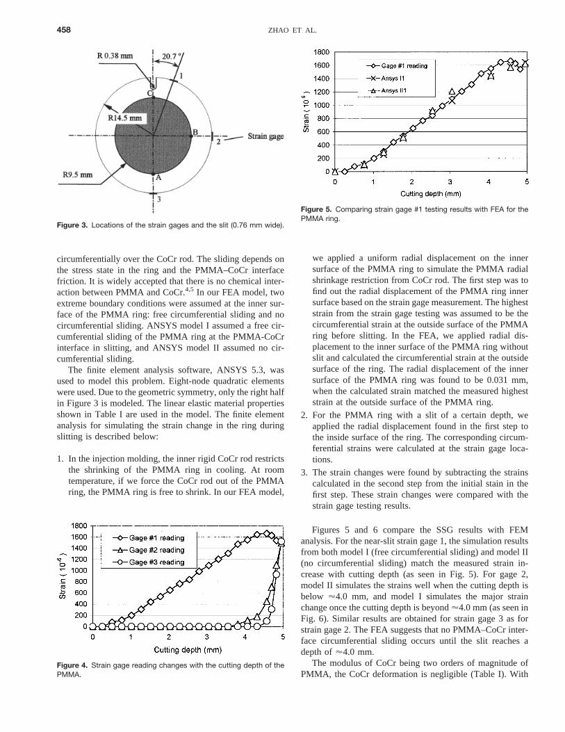
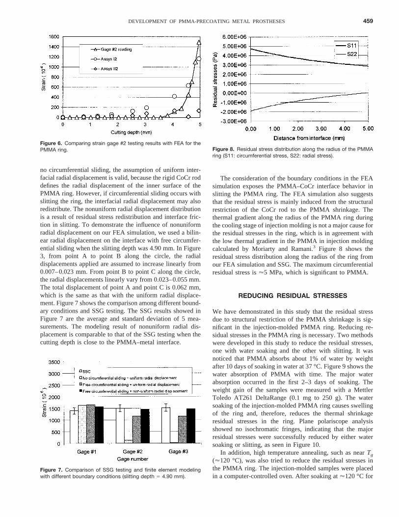
Figures 5 and 6 compare the SSG results with FEManalysis. For the near-slit strain gage 1, the simulation resultsfrom both model I (free circumferential sliding) and model II(no circumferential sliding) match the measured strain in-crease with cutting depth (as seen in Fig. 5). For gage 2,model II simulates the strains well when the cutting depth isbelow '4.0 mm, and model I simulates the major strainchange once the cutting depth is beyond'4.0 mm (as seen inFig. 6). Similar results are obtained for strain gage 3 as forstrain gage 2. The FEA suggests that no PMMA–CoCr inter-face circumferential sliding occurs until the slit reaches adepth of'4.0 mm.
The modulus of CoCr being two orders of magnitude ofPMMA, the CoCr deformation is negligible (Table I). With
Figure 3. Locations of the strain gages and the slit (0.76 mm wide).
Figure 4. Strain gage reading changes with the cutting depth of thePMMA.
Figure 5. Comparing strain gage #1 testing results with FEA for thePMMA ring.
458 ZHAO ET AL.
no circumferential sliding, the assumption of uniform inter-facial radial displacement is valid, because the rigid CoCr roddefines the radial displacement of the inner surface of thePMMA ring. However, if circumferential sliding occurs withslitting the ring, the interfacial radial displacement may alsoredistribute. The nonuniform radial displacement distributionis a result of residual stress redistribution and interface fric-tion in slitting. To demonstrate the influence of nonuniformradial displacement on our FEA simulation, we used a bilin-ear radial displacement on the interface with free circumfer-ential sliding when the slitting depth was 4.90 mm. In Figure3, from point A to point B along the circle, the radialdisplacements applied are assumed to increase linearly from0.007–0.023 mm. From point B to point C along the circle,the radial displacements linearly vary from 0.023–0.055 mm.The total displacement of point A and point C is 0.062 mm,which is the same as that with the uniform radial displace-ment. Figure 7 shows the comparison among different bound-ary conditions and SSG testing. The SSG results showed inFigure 7 are the average and standard deviation of 5 mea-surements. The modeling result of nonuniform radial dis-placement is comparable to that of the SSG testing when thecutting depth is close to the PMMA–metal interface.
The consideration of the boundary conditions in the FEAsimulation exposes the PMMA–CoCr interface behavior inslitting the PMMA ring. The FEA simulation also suggeststhat the residual stress is mainly induced from the structuralrestriction of the CoCr rod to the PMMA shrinkage. Thethermal gradient along the radius of the PMMA ring duringthe cooling stage of injection molding is not a major cause forthe residual stresses in the ring, which is in agreement withthe low thermal gradient in the PMMA in injection moldingcalculated by Moriarty and Ramani.3 Figure 8 shows theresidual stress distribution along the radius of the ring fromour FEA simulation and SSG. The maximum circumferentialresidual stress is'5 MPa, which is significant to PMMA.
REDUCING RESIDUAL STRESSES
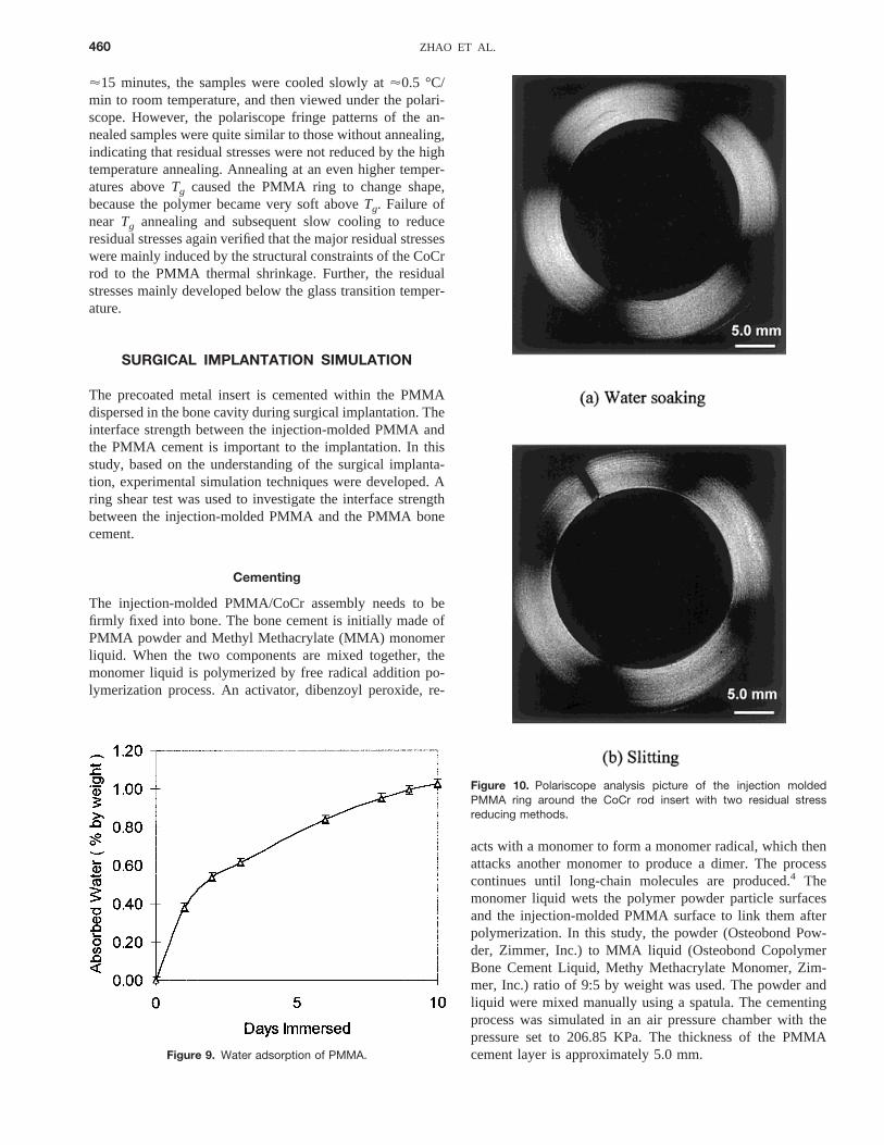
We have demonstrated in this study that the residual stressdue to structural restriction of the PMMA shrinkage is sig-nificant in the injection-molded PMMA ring. Reducing re-sidual stresses in the PMMA ring is necessary. Two methodswere developed in this study to reduce the residual stresses,one with water soaking and the other with slitting. It wasnoticed that PMMA absorbs about 1% of water by weightafter 10 days of soaking in water at 37 °C. Figure 9 shows thewater absorption of PMMA with time. The major waterabsorption occurred in the first 2–3 days of soaking. Theweight gain of the samples were measured with a MettlerToledo AT261 DeltaRange (0.1 mg to 250 g). The watersoaking of the injection-molded PMMA ring causes swellingof the ring and, therefore, reduces the thermal shrinkageresidual stresses in the ring. Plane polariscope analysisshowed no isochromatic fringes, indicating that the majorresidual stresses were successfully reduced by either watersoaking or slitting, as seen in Figure 10.
In addition, high temperature annealing, such as nearTg
('120 °C), was also tried to reduce the residual stresses inthe PMMA ring. The injection-molded samples were placedin a computer-controlled oven. After soaking at'120 °C for
Figure 6. Comparing strain gage #2 testing results with FEA for thePMMA ring.
Figure 7. Comparison of SSG testing and finite element modelingwith different boundary conditions (slitting depth 5 4.90 mm).
Figure 8. Residual stress distribution along the radius of the PMMAring (S11: circumferential stress, S22: radial stress).
459DEVELOPMENT OF PMMA-PRECOATING METAL PROSTHESES
'15 minutes, the samples were cooled slowly at'0.5 °C/min to room temperature, and then viewed under the polari-scope. However, the polariscope fringe patterns of the an-nealed samples were quite similar to those without annealing,indicating that residual stresses were not reduced by the hightemperature annealing. Annealing at an even higher temper-atures aboveTg caused the PMMA ring to change shape,because the polymer became very soft aboveTg. Failure ofnear Tg annealing and subsequent slow cooling to reduceresidual stresses again verified that the major residual stresseswere mainly induced by the structural constraints of the CoCrrod to the PMMA thermal shrinkage. Further, the residualstresses mainly developed below the glass transition temper-ature.
SURGICAL IMPLANTATION SIMULATION
The precoated metal insert is cemented within the PMMAdispersed in the bone cavity during surgical implantation. Theinterface strength between the injection-molded PMMA andthe PMMA cement is important to the implantation. In thisstudy, based on the understanding of the surgical implanta-tion, experimental simulation techniques were developed. Aring shear test was used to investigate the interface strengthbetween the injection-molded PMMA and the PMMA bonecement.
Cementing
The injection-molded PMMA/CoCr assembly needs to befirmly fixed into bone. The bone cement is initially made ofPMMA powder and Methyl Methacrylate (MMA) monomerliquid. When the two components are mixed together, themonomer liquid is polymerized by free radical addition po-lymerization process. An activator, dibenzoyl peroxide, re-
acts with a monomer to form a monomer radical, which thenattacks another monomer to produce a dimer. The processcontinues until long-chain molecules are produced.4 Themonomer liquid wets the polymer powder particle surfacesand the injection-molded PMMA surface to link them afterpolymerization. In this study, the powder (Osteobond Pow-der, Zimmer, Inc.) to MMA liquid (Osteobond CopolymerBone Cement Liquid, Methy Methacrylate Monomer, Zim-mer, Inc.) ratio of 9:5 by weight was used. The powder andliquid were mixed manually using a spatula. The cementingprocess was simulated in an air pressure chamber with thepressure set to 206.85 KPa. The thickness of the PMMAcement layer is approximately 5.0 mm.Figure 9. Water adsorption of PMMA.
Figure 10. Polariscope analysis picture of the injection moldedPMMA ring around the CoCr rod insert with two residual stressreducing methods.
460 ZHAO ET AL.
MMA Dipping
It was found that the injection-molded PMMA ring surface,as is, would form shallow cracks ('1 mm) if put into MMAliquid for a few minutes (3 min were used in this study).However, if the residual stresses in the ring were significantlyreduced by water soaking or slitting, cracks did not form.Dipping the PMMA-precoated CoCr insert into MMA liquidis another way used in this study to check the residual stressesin the injection-molded PMMA.
After water soaking and MMA dipping, the injection-molded PMMA rings were dried for about two weeks, andthen the dried samples were dipped into the MMA liquidagain. Cracks were not seen on the surface of the driedinjection-molded PMMA rings. Surface Optical Profilometeranalysis indicated that a thin layer ('30 mm) formed aroundthe injection-molded ring during the MMA dipping afterwater soaking. A slight circumferential compressive stresswas expected in the thin layer when the water in the ring wasdried out and the injection-molded PMMA shrunk. The com-pressive stress in the thin layer was thought to prevent thePMMA ring surface from cracking in the second MMAdipping.
Design of Implantation Simulation Processes
The following implantation simulation processes were de-signed and tested using ring shear method3:
Process #1: Injection molding — Cementing
Process #2: Injection molding — Water soaking — Ce-menting
Process #3: Injection molding — Water soaking — MMAdipping — Cementing
Process #4: Injection molding — Slitting — Cementing.
The ring shear test was performed in a Qtest tensile testingmachine at a speed of 5.08 mm/min. For each process, 5specimens were made and tested.
Implantation Simulation Results and Discussion
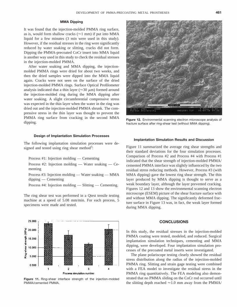
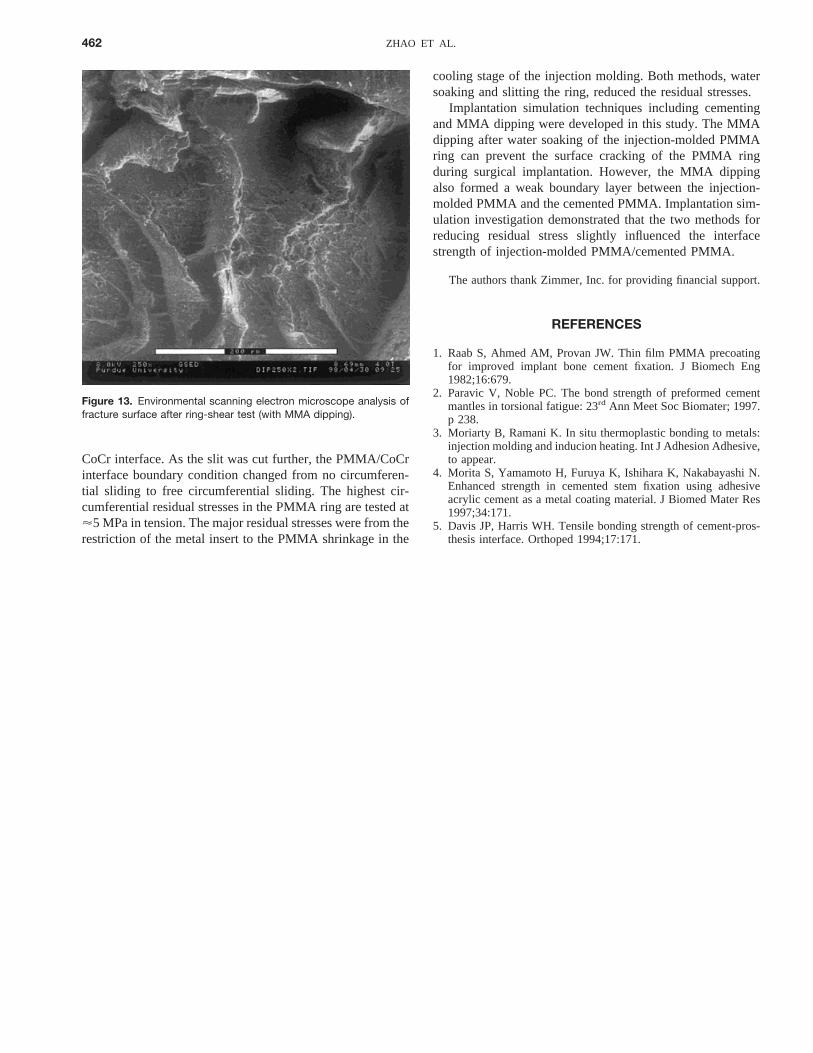
Figure 11 summarized the average ring shear strengths andtheir standard deviations for the four simulation processes.Comparison of Process #2 and Process #4 with Process #1indicated that the shear strength of injection-molded PMMA/cemented PMMA interface was slightly influenced by the tworesidual stress reducing methods. However, Process #3 (withMMA dipping) gave the lowest ring shear strength. The thinlayer produced by MMA dipping is thought to serve as aweak boundary layer, although the layer prevented cracking.Figures 12 and 13 show the environmental scanning electronmicroscope (ESEM) picture of the shear fracture surface withand without MMA dipping. The significantly deformed frac-ture surface in Figure 13 was, in fact, the weak layer formedduring MMA dipping.
CONCLUSIONS
In this study, the residual stresses in the injection-moldedPMMA coating were tested, modeled, and reduced. Surgicalimplantation simulation techniques, cementing and MMAdipping, were developed. Four implantation simulation pro-cesses of the precoated metal inserts were investigated.
The plane polariscope testing clearly showed the residualstress distribution along the radius of the injection-moldedPMMA ring. Slitting and strain gage testing were combinedwith a FEA model to investigate the residual stress in thePMMA ring quantitatively. The FEA modeling also demon-strated that no PMMA sliding on the CoCr rod occurred untilthe slitting depth reached'1.0 mm away from the PMMA/
Figure 11. Ring-shear interface strength of the injection-moldedPMMA/cemented PMMA.
Figure 12. Environmental scanning electron microscope analysis offracture surface after ring-shear test (without MMA dipping).
461DEVELOPMENT OF PMMA-PRECOATING METAL PROSTHESES
CoCr interface. As the slit was cut further, the PMMA/CoCrinterface boundary condition changed from no circumferen-tial sliding to free circumferential sliding. The highest cir-cumferential residual stresses in the PMMA ring are tested at'5 MPa in tension. The major residual stresses were from therestriction of the metal insert to the PMMA shrinkage in the
cooling stage of the injection molding. Both methods, watersoaking and slitting the ring, reduced the residual stresses.
Implantation simulation techniques including cementingand MMA dipping were developed in this study. The MMAdipping after water soaking of the injection-molded PMMAring can prevent the surface cracking of the PMMA ringduring surgical implantation. However, the MMA dippingalso formed a weak boundary layer between the injection-molded PMMA and the cemented PMMA. Implantation sim-ulation investigation demonstrated that the two methods forreducing residual stress slightly influenced the interfacestrength of injection-molded PMMA/cemented PMMA.
The authors thank Zimmer, Inc. for providing financial support.
REFERENCES
1. Raab S, Ahmed AM, Provan JW. Thin film PMMA precoatingfor improved implant bone cement fixation. J Biomech Eng1982;16:679.
2. Paravic V, Noble PC. The bond strength of preformed cementmantles in torsional fatigue: 23rd Ann Meet Soc Biomater; 1997.p 238.
3. Moriarty B, Ramani K. In situ thermoplastic bonding to metals:injection molding and inducion heating. Int J Adhesion Adhesive,to appear.
4. Morita S, Yamamoto H, Furuya K, Ishihara K, Nakabayashi N.Enhanced strength in cemented stem fixation using adhesiveacrylic cement as a metal coating material. J Biomed Mater Res1997;34:171.
5. Davis JP, Harris WH. Tensile bonding strength of cement-pros-thesis interface. Orthoped 1994;17:171.
Figure 13. Environmental scanning electron microscope analysis offracture surface after ring-shear test (with MMA dipping).
462 ZHAO ET AL.