Embed Size (px)
Citation preview
1
DEVELOPMENT OF NEXT-GENERATION ORNITHOPTER PROTOTYPES
John Wood, Daniel Jensen, Peter Leetsma, Christopher Gurrola, Daniel
Zheng, Matthew Sparta and Richard Culver,*
Timothy Philpot†
Michael VanOverloop, Kris Wood**
An “Ornithopter” is flying machine that uses an insect or bird type flapping
wing motion to develop required lift and thrust. In comparison with fixed-wing
or rotary-wing machines, ornithopters offer potential advantages that include in-
creased maneuverability, lower power consumption, higher adaptability to vary-
ing situations, and the ability to hover. The simple flapping motion used in exist-
ing commercial ornithopter micro air vehicles occurs only in the plane that is
perpendicular to the vehicle fuselage; however, birds and insects flap their wings
in a more complicated pattern. For example, a hummingbird is able to hover by
flapping its wings up and down, sweeping its wings forward and backward, and
twisting its wings to vary their angle of attack. This paper describes a project to
develop ornithopter flapping mechanisms that produce wing motions approach-
ing those of the hummingbird. The feasibility and effectiveness of several me-
chanisms are evaluated. This paper will also describe prototypes of the ornithop-
ter mechanism and present the results of testing.
INTRODUCTION
The research goal for this project was to investigate the use of both virtual and physical proto-
types that could be used for the study of ornithopter wing motion. A biological ornithopter (bird)
is a flying system that uses complex 3-axis wing rotational motion to produce both lift and thrust.
The project involved research into the design requirements necessary to produce an accurate si-
mulation of the 3D motion followed by development of virtual prototypes and concluding with
physical bench testing of two mechanisms developed to produce the bird-like wing motion. The
goal was to build a prototype mechanism that could move in two or three degrees of freedom ac-
tively, in order to more effectively mimic a bird’s flapping motion, in this case, a hummingbird’s.
The project was funded by Air Force Research Labs (AFRL) at Wright-Patterson Air Force Base
* Dept of Engineering Mechanics, US Air Force Academy, 2354 Fairchild Drive USAF Academy CO 80840, 719-333-
2531, [email protected] † Visiting Professor, Dept of Engineering Mechanics, US Air Force Academy.
** Dept. of Mechanical Engineering, Univ. of Texas, Austin, TX
(AFB), Ohio. The goal of the project was to d
models that simulate a hummingbird’s wing beat.
DERIVING PROTOTYPE REQUIREMENTS
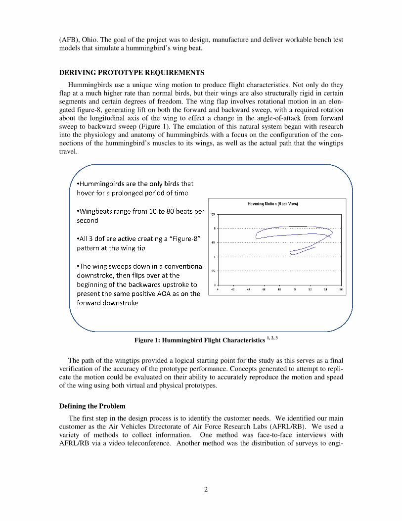
Hummingbirds use a unique wing motion to produce flight characteristics
flap at a much higher rate than normal birds
segments and certain degrees of freedom
gated figure-8, generating lift on
about the longitudinal axis of the wing to effect a change in the angle
sweep to backward sweep (Figure
into the physiology and anatomy of hummingbirds
nections of the hummingbird’s muscles to its wings, as well as the actual path that the wingtips
travel.
Figure
The path of the wingtips provided a logical starting point for the study as thi
verification of the accuracy of the prototype performance. Concepts generated to
cate the motion could be evaluated on their ability to accurately reproduce the motion and speed
of the wing using both virtual and physica
Defining the Problem
The first step in the design process
customer as the Air Vehicles Directorate of Air Force Research Labs (AFRL/RB).
variety of methods to collect inf
AFRL/RB via a video teleconference. Another method was the d
2
he goal of the project was to design, manufacture and deliver worka
mmingbird’s wing beat.
REQUIREMENTS
use a unique wing motion to produce flight characteristics. Not only do they
than normal birds, but their wings are also structurally rigid
and certain degrees of freedom. The wing flap involves rotational motion
8, generating lift on both the forward and backward sweep, with a required rotation
about the longitudinal axis of the wing to effect a change in the angle-of-attack from forward
Figure 1). The emulation of this natural system began with research
into the physiology and anatomy of hummingbirds with a focus on the configuration of the co
f the hummingbird’s muscles to its wings, as well as the actual path that the wingtips
Figure 1: Hummingbird Flight Characteristics 1, 2, 3
provided a logical starting point for the study as this serves as a final
verification of the accuracy of the prototype performance. Concepts generated to attempt to repl
otion could be evaluated on their ability to accurately reproduce the motion and speed
of the wing using both virtual and physical prototypes.
The first step in the design process is to identify the customer needs. We identified our main
customer as the Air Vehicles Directorate of Air Force Research Labs (AFRL/RB).
variety of methods to collect information. One method was face-to-face interviews with
AFRL/RB via a video teleconference. Another method was the distribution of surveys to
able bench test
. Not only do they
rigid in certain
flap involves rotational motion in an elon-
with a required rotation
ttack from forward
). The emulation of this natural system began with research
configuration of the con-
f the hummingbird’s muscles to its wings, as well as the actual path that the wingtips
s serves as a final
attempt to repli-
otion could be evaluated on their ability to accurately reproduce the motion and speed
to identify the customer needs. We identified our main
customer as the Air Vehicles Directorate of Air Force Research Labs (AFRL/RB). We used a
face interviews with
istribution of surveys to engi-
3
neers at AFRL/RB. From these different methods, we developed the customer needs (design re-
quirements) which would guide our project. The first customer needs relate to each of the three
DOFs; 120° (+/- 600) of flapping motion, 80°(+/- 40
0) of sweeping motion, and 60° (+/- 30
0) of
either active or passive twisting motion. The final customer need we determined is that the me-
chanism would need to be capable of maintaining a constant frequency of at least 15 Hz while
being able to vary the amplitude. Table 1 below summarizes these customer needs.
Table 1: Design Requirements
Customer Needs
Flap 120°
Sweep 80°
Twist 60°
Frequency 15 Hz
Generating Concepts to Satisfy the Design Requirements
After developing the customer needs (design requirements) for the project, we focused on ge-
nerating concepts. We investigated other universities’ and individuals’ research into developing
ornithopters 1,2, 4
. Because very few solutions have been proposed for 2 or 3 degree of freedom
motion for these systems, we also employed a variety of techniques for generating completely
new solutions for the problem. One of these techniques is called functional decomposition.
Functional decomposition is a method that helps designers describe what a product will be re-
quired to do (functions), not how it will accomplish these tasks (embodiment). There are a num-
ber of different ways to accomplish this functional decomposition with common methods includ-
ing function trees and function structures5. Functional decomposition combines with morpholog-
ical analysis to provide a method for organizing potential embodiments for each function.
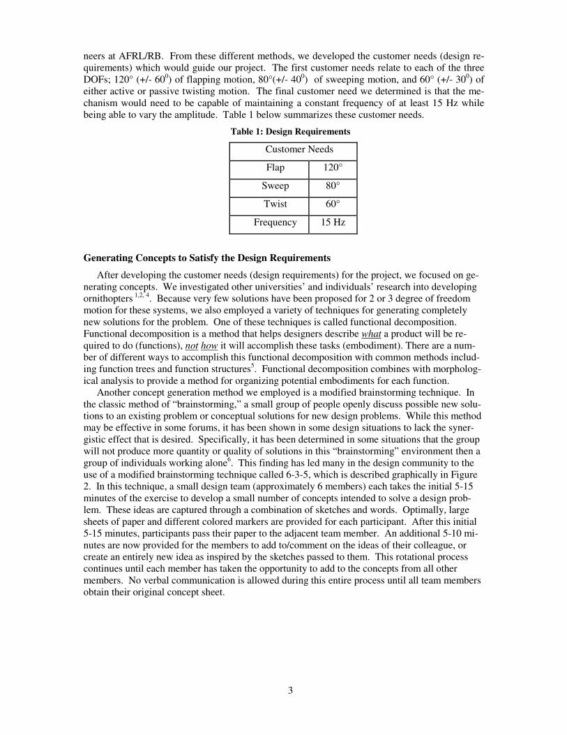
Another concept generation method we employed is a modified brainstorming technique. In
the classic method of “brainstorming,” a small group of people openly discuss possible new solu-
tions to an existing problem or conceptual solutions for new design problems. While this method
may be effective in some forums, it has been shown in some design situations to lack the syner-
gistic effect that is desired. Specifically, it has been determined in some situations that the group
will not produce more quantity or quality of solutions in this “brainstorming” environment then a
group of individuals working alone6. This finding has led many in the design community to the
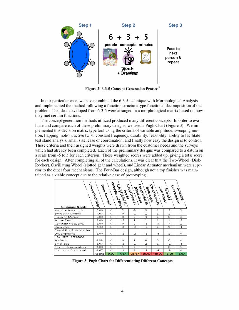
use of a modified brainstorming technique called 6-3-5, which is described graphically in Figure
2. In this technique, a small design team (approximately 6 members) each takes the initial 5-15
minutes of the exercise to develop a small number of concepts intended to solve a design prob-
lem. These ideas are captured through a combination of sketches and words. Optimally, large
sheets of paper and different colored markers are provided for each participant. After this initial
5-15 minutes, participants pass their paper to the adjacent team member. An additional 5-10 mi-
nutes are now provided for the members to add to/comment on the ideas of their colleague, or
create an entirely new idea as inspired by the sketches passed to them. This rotational process
continues until each member has taken the opportunity to add to the concepts from all other
members. No verbal communication is allowed during this entire process until all team members
obtain their original concept sheet.
4
Figure 2: 6-3-5 Concept Generation Process5
In our particular case, we have combined the 6-3-5 technique with Morphological Analysis
and implemented the method following a function structure type functional decomposition of the
problem. The ideas developed from 6-3-5 were arranged in a morphological matrix based on how
they met certain functions.
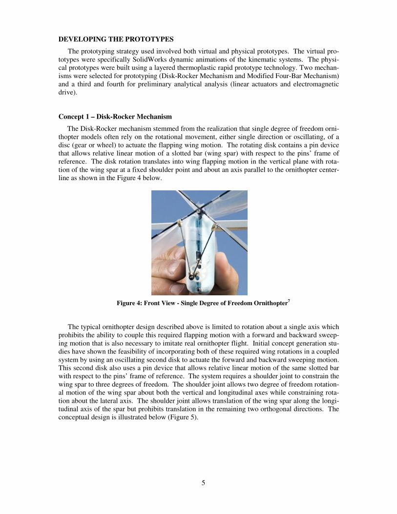
The concept generation methods utilized produced many different concepts. In order to eva-
luate and compare each of these preliminary designs, we used a Pugh Chart (Figure 3). We im-
plemented this decision matrix type tool using the criteria of variable amplitude, sweeping mo-
tion, flapping motion, active twist, constant frequency, durability, feasibility, ability to facilitate
test stand analysis, small size, ease of coordination, and finally how easy the design is to control.
These criteria and their assigned weights were drawn from the customer needs and the surveys
which had already been completed. Each of the preliminary designs was compared to a datum on
a scale from -5 to 5 for each criterion. These weighted scores were added up, giving a total score
for each design. After completing all of the calculations, it was clear that the Two-Wheel (Disk-
Rocker), Oscillating Wheel (slotted gear and wheel), and Linear Actuator mechanism were supe-
rior to the other four mechanisms. The Four-Bar design, although not a top finisher was main-
tained as a viable concept due to the relative ease of prototyping.
Figure 3: Pugh Chart for Differentiating Different Concepts
Step 1 Step 2 Step 3
people concepts minutes
6 + 3 + 56 + 3 + 56 + 3 + 56 + 3 + 5
Words Words Words Words + Drawings+ Drawings+ Drawings+ Drawings
Pass to next
person & repeat
5
DEVELOPING THE PROTOTYPES
The prototyping strategy used involved both virtual and physical prototypes. The virtual pro-
totypes were specifically SolidWorks dynamic animations of the kinematic systems. The physi-
cal prototypes were built using a layered thermoplastic rapid prototype technology. Two mechan-
isms were selected for prototyping (Disk-Rocker Mechanism and Modified Four-Bar Mechanism)
and a third and fourth for preliminary analytical analysis (linear actuators and electromagnetic
drive).
Concept 1 – Disk-Rocker Mechanism
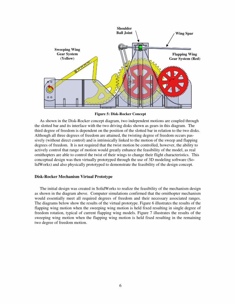
The Disk-Rocker mechanism stemmed from the realization that single degree of freedom orni-
thopter models often rely on the rotational movement, either single direction or oscillating, of a
disc (gear or wheel) to actuate the flapping wing motion. The rotating disk contains a pin device
that allows relative linear motion of a slotted bar (wing spar) with respect to the pins’ frame of
reference. The disk rotation translates into wing flapping motion in the vertical plane with rota-
tion of the wing spar at a fixed shoulder point and about an axis parallel to the ornithopter center-
line as shown in the Figure 4 below.
Figure 4: Front View - Single Degree of Freedom Ornithopter7
The typical ornithopter design described above is limited to rotation about a single axis which
prohibits the ability to couple this required flapping motion with a forward and backward sweep-
ing motion that is also necessary to imitate real ornithopter flight. Initial concept generation stu-
dies have shown the feasibility of incorporating both of these required wing rotations in a coupled
system by using an oscillating second disk to actuate the forward and backward sweeping motion.
This second disk also uses a pin device that allows relative linear motion of the same slotted bar
with respect to the pins’ frame of reference. The system requires a shoulder joint to constrain the
wing spar to three degrees of freedom. The shoulder joint allows two degree of freedom rotation-
al motion of the wing spar about both the vertical and longitudinal axes while constraining rota-
tion about the lateral axis. The shoulder joint allows translation of the wing spar along the longi-
tudinal axis of the spar but prohibits translation in the remaining two orthogonal directions. The
conceptual design is illustrated below (Figure 5).
6
Figure 5: Disk-Rocker Concept
As shown in the Disk-Rocker concept diagram, two independent motions are coupled through
the slotted bar and its interface with the two driving disks shown as gears in this diagram. The
third degree of freedom is dependent on the position of the slotted bar in relation to the two disks.
Although all three degrees of freedom are attained, the twisting degree of freedom occurs pas-
sively (without direct control) and is intrinsically linked to the motion of the sweep and flapping
degrees of freedom. It is not required that the twist motion be controlled, however, the ability to
actively control that range of motion would greatly enhance the feasibility of the model, as real
ornithopters are able to control the twist of their wings to change their flight characteristics. This
conceptual design was then virtually prototyped through the use of 3D modeling software (So-
lidWorks) and also physically prototyped to demonstrate the feasibility of the design concept.
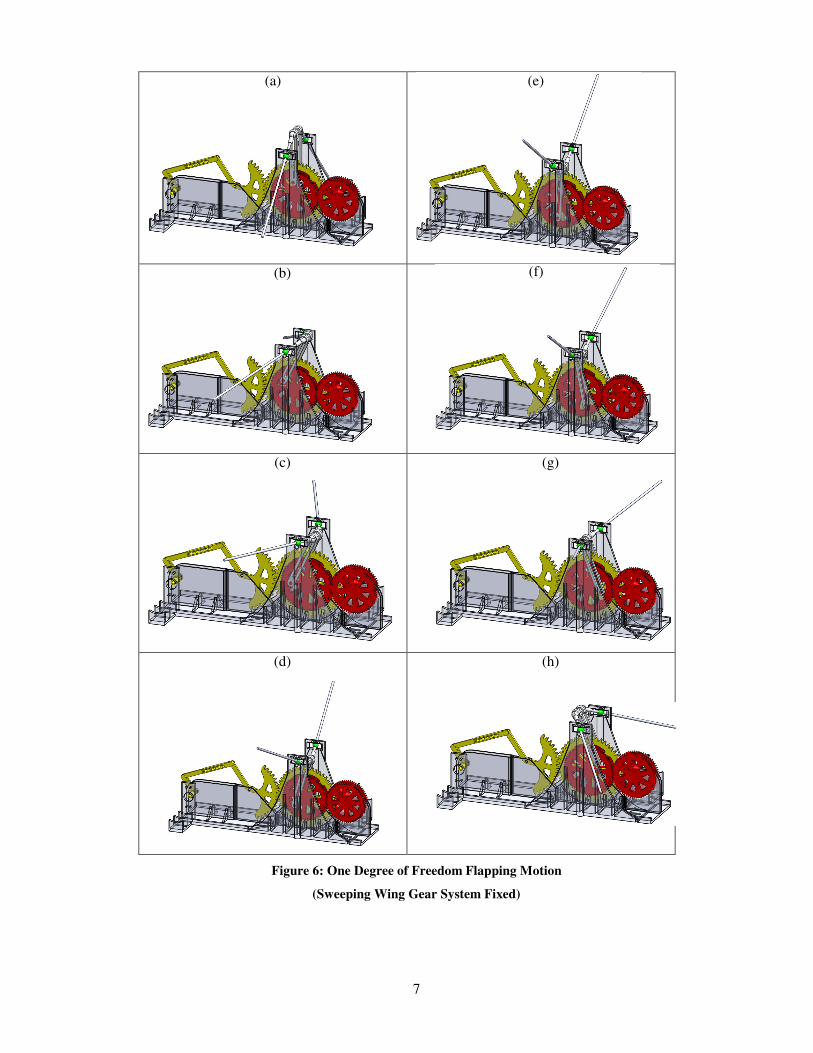
Disk-Rocker Mechanism Virtual Prototype
The initial design was created in SolidWorks to realize the feasibility of the mechanism design
as shown in the diagram above. Computer simulations confirmed that the ornithopter mechanism
would essentially meet all required degrees of freedom and their necessary associated ranges.
The diagrams below show the results of the virtual prototype. Figure 6 illustrates the results of the
flapping wing motion when the sweeping wing motion is held fixed resulting in single degree of
freedom rotation, typical of current flapping wing models. Figure 7 illustrates the results of the
sweeping wing motion when the flapping wing motion is held fixed resulting in the remaining
two degree of freedom motion.
Flapping Wing
Gear System (Red)
Sweeping Wing
Gear System
(Yellow)
Wing Spar
Shoulder
Ball Joint
7
(a)
(b)
(c)
(g)
(d)
(h)
Figure 6: One Degree of Freedom Flapping Motion
(Sweeping Wing Gear System Fixed)
(e)
(f)
8
(a)
(e)
(b)
(f)
(c)
(g)
(d)
(h)
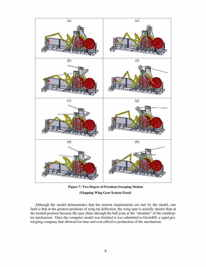
Figure 7: Two Degree of Freedom Sweeping Motion
(Flapping Wing Gear System Fixed)
Although the model demonstrates that the motion requirements are met by the model, one
fault is that at the greatest positions of wing tip deflection, the wing spar is actually shorter than at
the neutral position because the spar slides through the ball joint at the “shoulder” of the ornithop-
ter mechanism. Once the computer model was finished it was submitted to GrowIt®, a rapid pro-
totyping company that allowed for time and cost-effective production of the mechanism.
9
Disk-Rocker Mechanism Physical Prototype
Physical prototyping plays a critical role in the development of conceptual designs. The ability
to produce prototypes quickly (rapid prototyping) and cost effectively provides an additional tool
for the visualization, modification and refinement of mechanisms involving relative motion be-
tween components. In the case of the Disk-Rocker concept, the virtual prototype worked essen-
tially as expected. However, practical aspects such as gravity, momentum, friction, and other
phenomena affect the system while it is operating.
The first prototype we fabricated quickly demonstrated the need to pursue subtle design
changes. The rapid-prototyped model was modified to accept a small 9V DC electric motor to
drive both the flapping wing gear system and the sweeping wing gear system. Because of the low
strength properties of the gear teeth, repeated failures occurred due to the difficulty of overcom-
ing friction between the mechanism components. Key changes were made to reduce the load on
the structure, primarily by removing mass from the moving parts in ways that would not greatly
affect their structural integrity. After the final design changes were made the mechanism was able
to sustain flapping and sweeping motions up to 4.5 Hz. This demonstrated that plastic prototypes
were feasible for demonstrating the physical motion necessary to meet design requirements, how-
ever the material selection process would be essential in producing a mechanism that can sustain
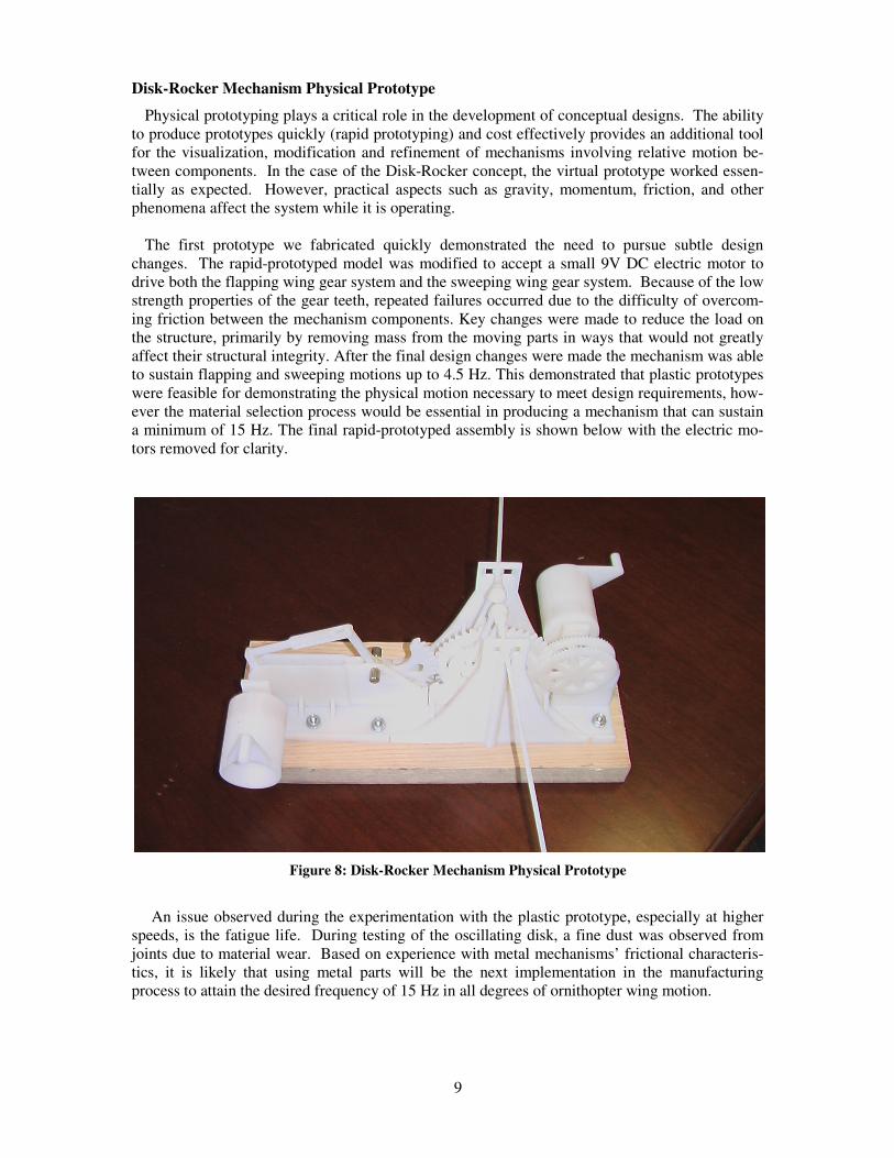
a minimum of 15 Hz. The final rapid-prototyped assembly is shown below with the electric mo-
tors removed for clarity.
Figure 8: Disk-Rocker Mechanism Physical Prototype
An issue observed during the experimentation with the plastic prototype, especially at higher
speeds, is the fatigue life. During testing of the oscillating disk, a fine dust was observed from
joints due to material wear. Based on experience with metal mechanisms’ frictional characteris-
tics, it is likely that using metal parts will be the next implementation in the manufacturing
process to attain the desired frequency of 15 Hz in all degrees of ornithopter wing motion.
10
Concept 2 – Modified Four-Bar Mechanism
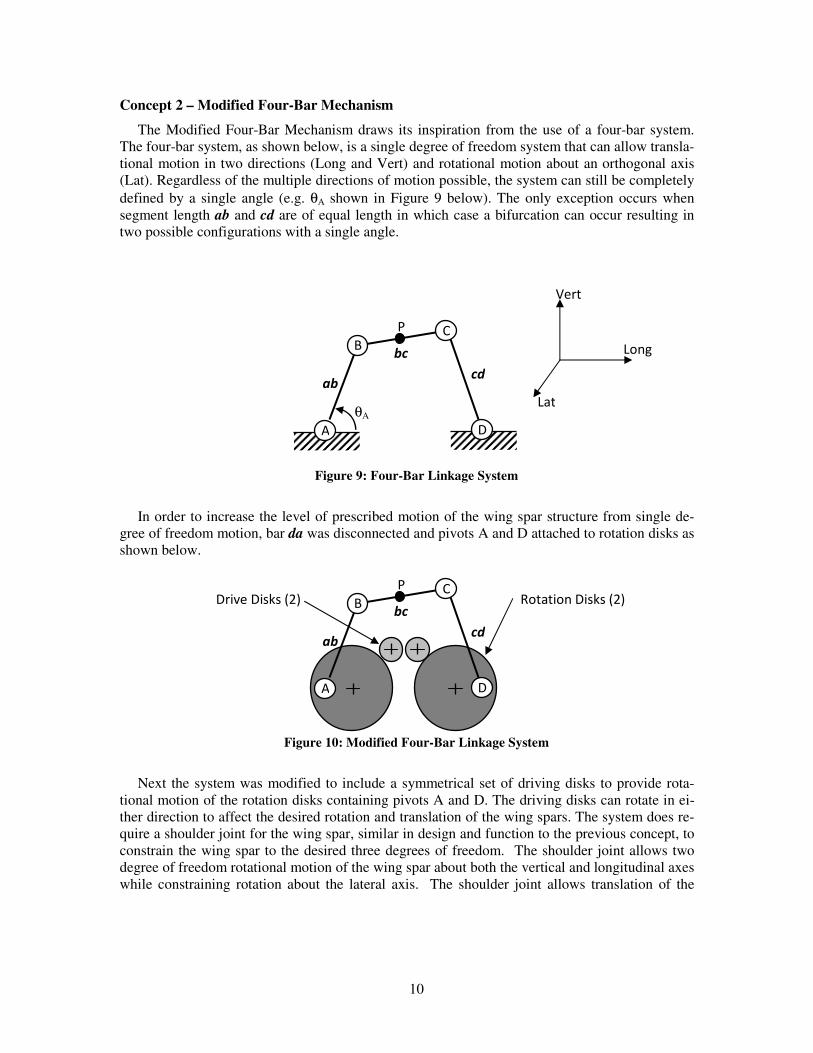
The Modified Four-Bar Mechanism draws its inspiration from the use of a four-bar system.
The four-bar system, as shown below, is a single degree of freedom system that can allow transla-
tional motion in two directions (Long and Vert) and rotational motion about an orthogonal axis
(Lat). Regardless of the multiple directions of motion possible, the system can still be completely
defined by a single angle (e.g. θA shown in Figure 9 below). The only exception occurs when
segment length ab and cd are of equal length in which case a bifurcation can occur resulting in
two possible configurations with a single angle.
Figure 9: Four-Bar Linkage System
In order to increase the level of prescribed motion of the wing spar structure from single de-
gree of freedom motion, bar da was disconnected and pivots A and D attached to rotation disks as
shown below.
Figure 10: Modified Four-Bar Linkage System
Next the system was modified to include a symmetrical set of driving disks to provide rota-
tional motion of the rotation disks containing pivots A and D. The driving disks can rotate in ei-
ther direction to affect the desired rotation and translation of the wing spars. The system does re-
quire a shoulder joint for the wing spar, similar in design and function to the previous concept, to
constrain the wing spar to the desired three degrees of freedom. The shoulder joint allows two
degree of freedom rotational motion of the wing spar about both the vertical and longitudinal axes
while constraining rotation about the lateral axis. The shoulder joint allows translation of the
A D
B C
θA
P
ab cd
bc Long
Lat
Vert
A D
B C P
ab cd
bc Drive Disks (2) Rotation Disks (2)
11
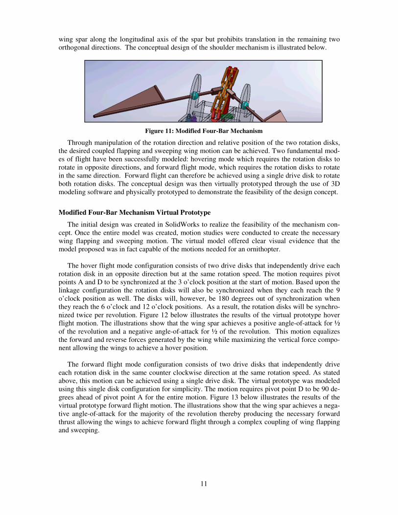
wing spar along the longitudinal axis of the spar but prohibits translation in the remaining two
orthogonal directions. The conceptual design of the shoulder mechanism is illustrated below.
Figure 11: Modified Four-Bar Mechanism
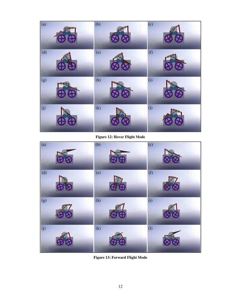
Through manipulation of the rotation direction and relative position of the two rotation disks,
the desired coupled flapping and sweeping wing motion can be achieved. Two fundamental mod-
es of flight have been successfully modeled: hovering mode which requires the rotation disks to
rotate in opposite directions, and forward flight mode, which requires the rotation disks to rotate
in the same direction. Forward flight can therefore be achieved using a single drive disk to rotate
both rotation disks. The conceptual design was then virtually prototyped through the use of 3D
modeling software and physically prototyped to demonstrate the feasibility of the design concept.
Modified Four-Bar Mechanism Virtual Prototype
The initial design was created in SolidWorks to realize the feasibility of the mechanism con-
cept. Once the entire model was created, motion studies were conducted to create the necessary
wing flapping and sweeping motion. The virtual model offered clear visual evidence that the
model proposed was in fact capable of the motions needed for an ornithopter.
The hover flight mode configuration consists of two drive disks that independently drive each
rotation disk in an opposite direction but at the same rotation speed. The motion requires pivot
points A and D to be synchronized at the 3 o’clock position at the start of motion. Based upon the
linkage configuration the rotation disks will also be synchronized when they each reach the 9
o’clock position as well. The disks will, however, be 180 degrees out of synchronization when
they reach the 6 o’clock and 12 o’clock positions. As a result, the rotation disks will be synchro-
nized twice per revolution. Figure 12 below illustrates the results of the virtual prototype hover
flight motion. The illustrations show that the wing spar achieves a positive angle-of-attack for ½
of the revolution and a negative angle-of-attack for ½ of the revolution. This motion equalizes
the forward and reverse forces generated by the wing while maximizing the vertical force compo-
nent allowing the wings to achieve a hover position.
The forward flight mode configuration consists of two drive disks that independently drive
each rotation disk in the same counter clockwise direction at the same rotation speed. As stated
above, this motion can be achieved using a single drive disk. The virtual prototype was modeled
using this single disk configuration for simplicity. The motion requires pivot point D to be 90 de-
grees ahead of pivot point A for the entire motion. Figure 13 below illustrates the results of the
virtual prototype forward flight motion. The illustrations show that the wing spar achieves a nega-
tive angle-of-attack for the majority of the revolution thereby producing the necessary forward
thrust allowing the wings to achieve forward flight through a complex coupling of wing flapping
and sweeping.
12
Figure 12: Hover Flight Mode
Figure 13: Forward Flight Mode
(a) (b) (c)
(d) (e) (f)
(g) (h) (i)
(j) (k) (l)
(a) (b) (c)
(d) (e) (f)
(g) (h) (i)
(j) (k) (l)
13
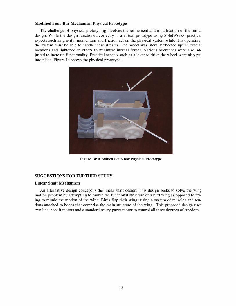
Modified Four-Bar Mechanism Physical Prototype
The challenge of physical prototyping involves the refinement and modification of the initial
design. While the design functioned correctly in a virtual prototype using SolidWorks, practical
aspects such as gravity, momentum and friction act on the physical system while it is operating;
the system must be able to handle these stresses. The model was literally “beefed up” in crucial
locations and lightened in others to minimize inertial forces. Various tolerances were also ad-
justed to increase functionality. Practical aspects such as a lever to drive the wheel were also put
into place. Figure 14 shows the physical prototype.
Figure 14: Modified Four-Bar Physical Prototype
SUGGESTIONS FOR FURTHER STUDY
Linear Shaft Mechanism
An alternative design concept is the linear shaft design. This design seeks to solve the wing
motion problem by attempting to mimic the functional structure of a bird wing as opposed to try-
ing to mimic the motion of the wing. Birds flap their wings using a system of muscles and ten-
dons attached to bones that comprise the main structure of the wing. This proposed design uses
two linear shaft motors and a standard rotary pager motor to control all three degrees of freedom.
14
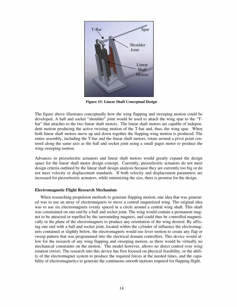
Figure 15: Linear Shaft Conceptual Design
The figure above illustrates conceptually how the wing flapping and sweeping motion could be
developed. A ball and socket “shoulder” joint would be used to attach the wing spar to the “T-
bar” that attaches to the two linear shaft motors. The linear shaft motors are capable of indepen-
dent motion producing the active twisting motion of the T-bar and, thus, the wing spar. When
both linear shaft motors move up and down together the flapping wing motion is produced. The
entire assembly, including the T-bar and the linear shaft motors, rotate around a pivot point cen-
tered along the same axis as the ball and socket joint using a small pager motor to produce the
wing sweeping motion.
Advances in piezoelectric actuators and linear shaft motors would greatly expand the design
space for the linear shaft motor design concept. Currently, piezoelectric actuators do not meet
design criteria outlined by the linear shaft design analysis because they are currently too big or do
not meet velocity or displacement standards. If both velocity and displacement parameters are
increased for piezoelectric actuators, while minimizing the size, there is promise for the design.
Electromagnetic Flight Research Mechanism
When researching propulsion methods to generate flapping motion, one idea that was generat-
ed was to use an array of electromagnets to move a central magnetized wing. The original idea
was to use six electromagnets evenly spaced in a circle around a central wing shaft. This shaft
was constrained on one end by a ball and socket joint. The wing would contain a permanent mag-
net to be attracted or repelled by the surrounding magnets, and could thus be controlled magneti-
cally in the plane of the electromagnets to produce any orientation of the wing desired. By affix-
ing one end with a ball and socket joint, located within the cylinder of influence the electromag-
nets contained or slightly below, the electromagnets would use lever motion to create any flap or
sweep pattern that was programmed into the electrical domain controllers. This device would al-
low for the research of any wing flapping and sweeping motion, as there would be virtually no
mechanical constraints on the motion. The model however, allows no direct control over wing
rotation (twist). The research into this device has first focused on physical feasibility, or the abili-
ty of the electromagnet system to produce the required forces at the needed times, and the capa-
bility of electromagnetics to generate the continuous smooth motions required for flapping flight.
Shoulder
Joint
T-Bar Spar
Linear
Shaft
Motors
15
The development of the electromagnet option began by searching for previous examples
of similar devices. In 1989, Yamaha received a patent (PN: 4801829; Electromagnetic Motor
Without Mechanical Motion Converter) on a device designed to allow two dimensional motion
control over a free floating central movable magnet. The original intent of this device was as an
alternative means of converting electrical energy into mechanical motion. The device described is
the fundamental unit of the proposed electromagnetic research device, a system that can control
the position of a moving component in a 2D plane through the use of electromagnets.
The engineers at Yamaha describe some of their outputs in the text of the patent, indicat-
ing that small defined motion control using this device is possible. However their primary focus
was the use of square waves and sine waves to achieve rectilinear and circular motion profiles.
The patent does not describe any attempts to use the device for any more complex motions, like
the near figure-eight of traditional flapping wing flight.
The electromagnetic prototype’s hurdles to overcome presently exist primarily in the con-
trol domain, as many of the limitations of electromagnetic force generation can be compensated
for by using the appropriate overall design including sufficient power and the geometry of the
magnets. As an example, electromagnets beyond a certain size may begin to retain small amounts
of magnetic flux for a short but non instantaneous amount of time after the current to the electro-
magnet has been removed. This means that electromagnets beyond a certain size cannot instantly
flip polarity, and must instead have a short amount of time to either allow the flux to dissipate, or
an excess amount of current to force the flux to change and still reach the desired levels of field
strength. This magnetic flux dissipation can be compensated for in the control domain by allotting
a higher than needed current to compensate for shunting the electromagnet, or by moving the ac-
tivation time slightly forward to reach full power at the needed time. This particular problem may
also be resolvable by using an array of small electromagnets with dissipation times that are trivial
with respect to the operational frequency.
We are currently working on making a small 1D rocking motion prototype that will help
to show the actual relations between many of the project’s physical parameters. This model
should help to define how large some of the electromagnetic response time problems will be, as
well as aid in the creation of a map of the forces that the electromagnet pair are able to produce at
different locations and how strongly they are able to influence the center rockers precise location.
This test model should allow more refined exploration into the overall feasibility as well as the
control requirements of the electromagnetic research option.
16
CONCLUSION
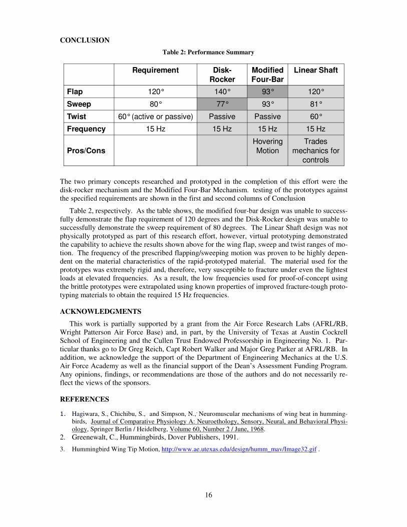
Table 2: Performance Summary
The two primary concepts researched and prototyped in the completion of this effort were the
disk-rocker mechanism and the Modified Four-Bar Mechanism. testing of the prototypes against
the specified requirements are shown in the first and second columns of Conclusion
Table 2, respectively. As the table shows, the modified four-bar design was unable to success-
fully demonstrate the flap requirement of 120 degrees and the Disk-Rocker design was unable to
successfully demonstrate the sweep requirement of 80 degrees. The Linear Shaft design was not
physically prototyped as part of this research effort, however, virtual prototyping demonstrated
the capability to achieve the results shown above for the wing flap, sweep and twist ranges of mo-
tion. The frequency of the prescribed flapping/sweeping motion was proven to be highly depen-
dent on the material characteristics of the rapid-prototyped material. The material used for the
prototypes was extremely rigid and, therefore, very susceptible to fracture under even the lightest
loads at elevated frequencies. As a result, the low frequencies used for proof-of-concept using
the brittle prototypes were extrapolated using known properties of improved fracture-tough proto-
typing materials to obtain the required 15 Hz frequencies.
ACKNOWLEDGMENTS
This work is partially supported by a grant from the Air Force Research Labs (AFRL/RB,
Wright Patterson Air Force Base) and, in part, by the University of Texas at Austin Cockrell
School of Engineering and the Cullen Trust Endowed Professorship in Engineering No. 1. Par-
ticular thanks go to Dr Greg Reich, Capt Robert Walker and Major Greg Parker at AFRL/RB. In
addition, we acknowledge the support of the Department of Engineering Mechanics at the U.S.
Air Force Academy as well as the financial support of the Dean’s Assessment Funding Program.
Any opinions, findings, or recommendations are those of the authors and do not necessarily re-
flect the views of the sponsors.
REFERENCES
1. Hagiwara, S., Chichibu, S., and Simpson, N.,, Neuromuscular mechanisms of wing beat in humming-
birds, Journal of Comparative Physiology A: Neuroethology, Sensory, Neural, and Behavioral Physi-
ology, Springer Berlin / Heidelberg, Volume 60, Number 2 / June, 1968.
2. Greenewalt, C., Hummingbirds, Dover Publishers, 1991.
3. Hummingbird Wing Tip Motion, http://www.ae.utexas.edu/design/humm_mav/Image32.gif .
Requirement Disk-
Rocker
Modified
Four-Bar
Linear Shaft
Flap 120° 140° 93° 120°
Sweep 80° 77° 93° 81°
Twist 60°(active or passive) Passive Passive 60°
Frequency 15 Hz 15 Hz 15 Hz 15 Hz
Pros/Cons
Hovering
Motion
Trades
mechanics for
controls

17
4. Mueller, T., Editor, Fixed and Flapping Wing Aerodynamics for Micro Air Vehicle Applications,
AIAA Publications, Volume 165, 2001.
5. Otto, K., Wood, K., Product Design: Techniques in Reverse Engineering and New Product Develop-
ment, Prentice Hall, 2001.
6. Mullen, B., C. Johnson, and E. Salas," Productivity Loss in Brainstorming Groups: A Meta-Analytic
Integration", Basic and Applied Social Psychology Vol. 12, No. 1, pp. 3-23, 1991.
7. Single DOF Ornithopter Mechanism, http://www.symscape.com/files/images/mav-ornithopter.jpg .
![Ornithopter Final Report · smaller Kinkade Park Hawk ornithopter. In this system, live video was transmitted to a portable LCD display unit [8]. Although ornithopter research and](https://img.pdfslide.us/doc/110x75/5e7f3dc14d823774c40e3e8b/ornithopter-final-report-smaller-kinkade-park-hawk-ornithopter-in-this-system.jpg)