Embed Size (px)
Citation preview

UCRL-JC-119707 PREPRINT
Development of Multianalyte Sensor Arrays for Continuous Monitoring of Pollutants
F.P. Milanovich R EC F I VED J.B. Richards
S.B. Brown B.G. Healey OCT 1 2 S. Chadha D. Walt S T I
for submittal to the on Field Screening Methods
Februa y 22-24,1995
January 1995
This is a preprint of a paper intended for publication in a journal or proceedings. Since changes may be made before publication, this preprint is made available with the understanding that it will not be cited or reproduced without the permission of the author.
DISCLAIMER
'#T&documpS was prepamd as an account of work sponsored by an agency of the ~ni+g'lcStptq Government. Neither the United States Government mrthe University of California nor any ofthdr employees, makes any warranty, express or implied, or
;719r";: .Prsumepo any legdliability or responsibility for the .ceuracy, completeness, or usefulness 7 t . . bf o$y infdrmation, apparatus, product, or process disdosed, or represents that its use
wouldnot infringeprivatelyowncd rights. Referenceherein toanyspeciticcommedd 8 f products, proccss, or service by trade name, trademark, manufadurcr, or otherwise,
doesnotmcessnrilywnstituteorimpiy itrendorsement, recommendation, orfavoring by the United States Government or the University of Caliioxnii The views and opinions of authom expressed herein do not necessarily state or nflect those of the United States Government or the University of California, and shall not be used for advertising or product endorsement purposes.

DISCLAIMER
Portions of this document may be illegible in electronic image products. Images are produced from the best available original document.
*
Development of Multianalyte Sensor Arrays for Continuous Monitoring of Pollutants
Brian G. Healey, Suneet Chadha, and David R. Walt Max Tishler Laboratory for Organic Chemistry
Department of Chemistry, Tufts University Medford, MA 02 155.
Fred P. Milanovieh, James Richards and Steve Brown Measurement Sciences Group
Physics Department
Livermore, CA 94550. Lawrence Livermore National Laboratory*
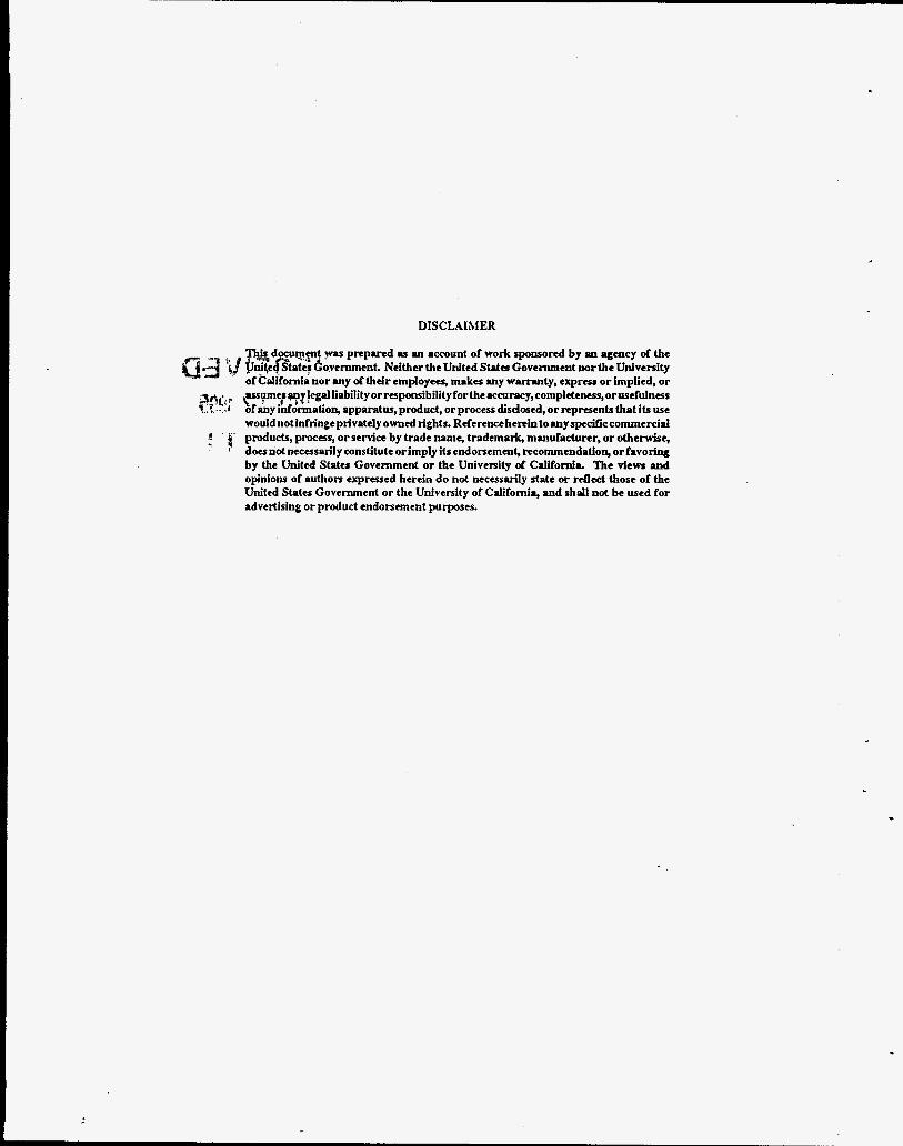
ABSTRACT Industrial development has led to the release of numerous hazardous materials into the
environment posing a potential threat to surrounding waters. Environmental analysis of sites contaminated by several chemicals calls for continuous monitoring of multiple analytes. Monitoring can be achieved by using imaging bundles (300400 Fm in diameter), containing several thousand individual optical fibers for the fabrication of sensors. Multiple sensor sites are created at the distal end of the fiber by immobilizing different analyte-specific fluorescent dyes. By coupling these imaging fibers to a charge coupled device (CCD), one has the ability to spatially and spectrally discriminate the multiple sensing sites simultaneously and hence monitor analyte concentrations.
INTRODUCTION The initiative towards remediation of ground and waste water facilities requires identification
and analysis of the numerous pollutant compounds present, as the initial step. Fiber-optic chemical sensors, which allow remote detection of analytes have proven to be an excellent alternative to traditional methods of analysis. A number of optical sensors have been described based on different chemical transduction mechanisms and optical properties. The small size of optical fibers, insensitivity to electrical interference and lack of the need for a reference sensor make these devices potentially suitable for remote applications2”. Indicators that are sensitive to analyte concentration and exhibit changes in absorbance or luminescence form the basis of such sensors. Traditionally, most multianalyte sensors have been merely several individual sensors fabricated into a sensor bundle or array. This approach has limitations in the sense that the size of the array increases proportionally with each added individual sensing component. We have demonstrated the capability of placing multiple indicator chemistries, which serve as discrete sensing sites, at the distal end of a single imaging fiber‘. Typically an imaging fiber is 300-400 pm in diameter consisting of thousands of individual fibers. The discrete sensing sites are the result of photopolymerizing different indicators in a polymer matrix on multiple regions of the fiber. By coupling the imaging fibers to a charge coupled device detector (CCD), one has the ability to spatially and spectrally discriminate the multiple sensing sites simultaneously and hence monitor analyte concentrations. Here we describe the indicator chemistry and immobilization procedures developed for a pH, Alk and hydrocarbon sensors.
*This work was performed under the auspices of the U.S. Department of Energy by Lawrence Livermore National Laboratory under contract W-7405-ENG-48

INDICATOR CHEMISTRY
Most pH indicators possess a limited dynamic range, therefore muttiple indicators must be employed to obtain sensors that cover a wider pH range*". Fluorescent pH indicators are typically weak acid dyes whose dissociated and undissociated forms have different absorption or fluorescent properties in the pH range of interest. Most investigations of optical pH sensors have concentrated on developing sensors for biomedical applications because of the nmow pH range covere& with emphasis on achieving improved sensitivity and precision. As a result, fluorescent indicators developed outside this range are few.
The multiple pH indicators used should have a strong absorption within the wavelength range 400- 700 nm to allow use of inexpensive optics. Furthermore the indicators should possess considerable photo- and chemical stability, lack of toxicity and the availability of functional groups capable of chemical immobilization. Eosin and fluorescein are fluorescent indicators sensitive in the pH range 2-8 pH units and may be hnctionalized easily for immobilization.
Both eosin and fluorescein are commercially available as their amine derivative. The amine is functionalized with an acrylate group via reaction with acryloyl chloride. These modified dyes are photo- polymerized with HEMA at the distal end of the fiber and are immobilized in the polymer matrix. Prior to immobilization of the dye the distal end of the fiber is functionalized to permit covalent bonding.
*
Functionalization of Indicators ym COOH ____) q C ' o y ) $ y \ COOH
/ /
w T-- 0
Fluoresceinamime
0 oJJy$ 7" ;Tr COOH
COOH ____) \
/ /
NH2 0
Aminoeosin
Silanization of Fibers
3-(trimethoxysilyl) propylmethacrylate
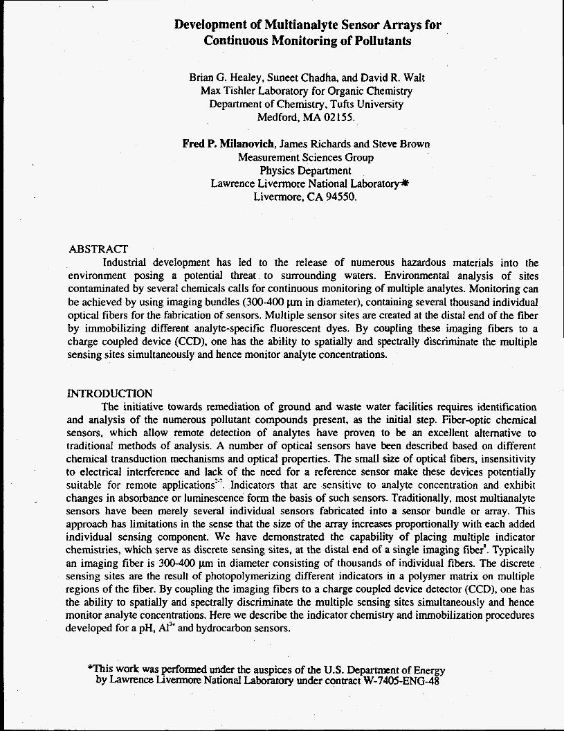
Immobilization
HO’ @ + hydroxy ethyl methacrylate ethyfenegylcol dimethacfylate
+ Indicator
Initiator, hv I Dye Immobilized on Fiber
Eosin shows maximum sensitivity in the 2-6 pH range, while fluorescein is most sensitive in the 5-8 pH range. Consequently pH measurements in the range 2-8 pH units can be achieved using immobilized eosin and fluorescein.
- AI3+ An aluminum ion sensor may be prepared by immobilizing a non-fluorescent ligand that forms a fluorescent complex in the presence of the metal ions. The concentration of the fluorophore and the immobilization procedure play a crucial role on the fluorescence intensity of the indicator. Furthermore, complex formation for most ligands involves displacement of one or more protons. This means that the equilibrium for the indicator reaction is described by a pH-dependent conditional formation constant. The measurement, therefore, must be done at a constant pH or be corrected for variations in pH.
Aluminum determination using fluorescence measurements has been widely studied and numerous methods have been proposed”. To date all sensors designed for Alk use the parent fluorogenic compound in solution or adsorbed on a solid support such as cellulose or an ion exchange resin”. Immobilization of the indicator in such a non-specific manner often leads to a deactivation of the AI* binding sites and an increase in background fluorescence. Furthermore, as the complex formation is not reversible, the initial increase in fluorescence intensity observed in the presence of A13’ rapidly plateaus once the binding sites get saturated.
We have designed a sensor that not only has the indicator chemically immobilized on the distal end of the optical fiber but also exploits the diffusion of the AIk ions through the polymer matrix to extend the life of the sensor. Lumogallion a non-fluorescent azo compound forms stable fluorescent complexes with AI3’ in slightly acidic media showing an emission maximum at 580 nm with excitation at 490 nm’”.
Lumogallion is functionalized as outlined below to provide labile double bonds which are copolymerized photochemically along with the polymer matrix. AI3+ binds irreversibly to lumogallion, consequently the concentration of Ai3’ is measured as a function of the rate of increase in fluorescence intensity. Furthermore, the rate is not only dependent on the formation constant of the complex but also on the rate of diffusion of the AIk ions through the polymer matrix.

Functionalization of Lumogalliorl U a
a
Hvdrocarbons Organic vapors are partitioned into a polymer membrane to varying extents depending upon the polarity of the polymer matrix. Neutral membrane probes have spectroscopic properties that are sensitive to changes in the microenvironment, thus providing a transduction mechanism for monitoring the adsorption of organic vapors into the polymer membrane. Such a probe immobilized in a membrane exhibits solvachromic behavior in its fluorescence spectra and forms the basis of the hydrocarbon sensor. Construction of such a sensor typically involves deposition of a suitabie polymer containing a membrane probe at the distal end of the fiber via photopolymerization or dip coating. Different dyedpolymer combinations are being identified for maximum spectral variations when exposed to organic vapors.
Siloxanes and certain modified polybutadienes are known to form gas permeable membranes which absorb low levels of organic vapors reversibly. Numerous siloxane based polymers with varying porosity and polarity are being tested. PS802 and PS85 1 are two such representative photopolymerizable polymers obtained from United Technologies.
Nile Red is one of the fluorescent dyes under review. Nile Red is a phenoxazine micro- environment sensitive dye which is almost non-fluorescent in water and polar solvents but shows a large blue shifted fluorescence depending upon the polarity of the medium. This dye is incorporated in photopolymerizable siloxanes and immobilized on optical fibers.
Nile Red
The varying polarity of different hydrocarbons is responsible for the solvachromic shifts in the Nile Red fluorescence.
Spectral shifts and intensity variations using numerous dydpolymer combinations immobilized on fiber optic bundles are being studied. Illumination and simultaneous measurement of the emanating fluorescence would serve as inputs for developing a recognition pattern based on a neural network. It is believed that once a reliable recognition pattern is reached such a sensor can be applied to unknown organic vaporsz0.
EXPERIMENTAL Photodeposition of analyte-sensitive polymer was performed using a 75 W Hg-Xe lamp. The
excitation light is collimated and focused onto a pinhole. The pinhole is then imaged onto the proximal end of an imaging fiber (Sumitomo, 350 pn) with a 15x reflecting objective, illuminating a small area of the imaging fiber. The fiber is held in a fiber chuck mounted in a x-y positioner with 360" rotation which allows for precise positioning of the imaged pinhole on the fiber. The distal end is then placed in a monomer solution and is irradiated to allow formation of the polymer at the illuminated area The excitation light is then moved onto a different region of the fiber and the polymerization process repeated to give additional analyte-sensitive polymer matrices.
Fluorescence measurements are made with a modified Olympus Fluorescence Microscope. Collimated light from a 75W Xe lamp passes through an excitation filter and is reflected towards the fiber by a long pass dichroic. The light is then focused on the proximal end of the fiber with an objective. Upon excitation, the fluorescence of the analyte-sensitive polymer matrices returns through the fiber, passes through the dichroic and is filtered at the appropriate emission wavelengths. The fluorescence is spatially detected by a CCD camera controlled by a Macintosh Quadra 950 with Signal Analytics image processing software.
.
RESULTS Figure 1 shows a schematic of a pHhydrocarbon array with seven analyte-sensitive polymer
matrices and fluorescent images of the sensor under various conditions. The sensor is comprised of three pH sensitive matrices containing eosin, two pH sensitive matrices containing fluorescein and two hydrocarbon sensitive matrices of two different photopolymerizable siloxanes. For eosin and fluorescein, fluorescence is monitored at 530 nm with excitation at 490 nm. The hydrocarbon sensitive matrices containing Nile Red, fluoresce at 600 nm with excitation at 490 nm.
Panel A shows the increase in fluorescence matrices 5 and 7 upon introduction of CH,CI, vapors and return to baseline fluorescence when pure N1 is reintroduced. Panel A also shows that iheie is no significant fluorescence change of the other matrices upon introduction of CH,CI, vapors. Panel B shows the response of the pH sensitive matrices. Between pH 2-6 the eosin-containing matrices show the maximum change in fluorescence, while the fluorescein-containing matrices are most sensitive in the pH range of 5-8.
Fgure 2 shows response of an imaging fiber containing five aluminum sensing polymer matrices containing lumogallion. The changes in fluorescence intensity at 530 nm with excitation at 490 nm is monitored for lumogallion. The presence of aluminum produces an increase in fluorescence as shown in the figure. The rate of increase of fluorescence is calculated and correlated with the amount of aluminum present.
CONCLUSIONS We have demonstrated the capability of placing multiple indicator chemistries which serve as
discrete sensing sites at the distal end of a single imaging fiber. The discrete sensing sites are the result of photopolymerizing different indicators in a polymer matrix on multiple regions of the fiber. By coupling the imaging fibers to a charge coupled device detector (CCD), it is possible to spatially and spectrally discriminate the multiple sensing sites simultaneously and hence monitor analyte concentrations. We have developed indicator chemistries for wide range pH, AI" and hydrocarbons which can be immobilized as discrete sensing sites on a single fiber.
The concept of multianalyte sensors is certainly not limited to the analytes mentioned above. As additional analyte-specific reagents and other transduction mechanisms are identified, these sensors will find greater scope of applicability. Due to its miniature design and ease of fabrication, such sensors should be of particular value for continuous in-situ monitoring of pollutants.

ACKNOWLEDGMENTS
This work was supported by grants from DOE, Office of Technology Development.
REFERENCES
I.
2.
3.
4.
5.
6. 7.
8. 9. 10. 11. 12. 13. 14. 15. 16. 17.
18. 19. 20.
Wise, D. L., and Wingard, L. B., (eds.) in Biosensors with Fiberoptics, Humana Press, Clifton, New Jersey, 1991. Leiner, M. P. J., and Wolfbeis, O.S., in Fiber Optic Chemical Sensors and Biosensors, Wolfbeis, O.S. (ed.) , VoI. 1, CRC Press, Boca Raton, 1991, Ch. 8. pp 359-384. Wolfbeis, O.S., in Fiber Optic Chemical Sensors and Biosensors, Wolfbeis, O.S. (4.) , Vol. 2, CRC Press, Boca Raton, 1991, Ch. 19. pp 267-300. Peterson, J. I., Goldstein, S. R., Fitzgerald, R. V., and Buckhold, D. K., Anal. Chem. 1980,53,864- 869. Yafuso, M., Arick, S. A., Hannsmann, D., Holody, M. Miller, W. W., and Yan, C. F., Proc. S H E 1989, vol 1067,3743. Boisde, G., Blanc, F., and Perez, J. J., Talanta, 1988,2,75-82. Angel, S . M. and Poco, J.F., Final Report, Lawrence Livermore National Laboratory, CA, June 1989. Barnard, S., Walt, D. R., 1991, Nature 353,338-340. Wolfbeis, 0. S. , and Frez, Z. Anal. Chem. 1986,325,387. Jordan, D. M., Walt, D. R., Milanovich, F. P., Anal. Chem. 1987,59,437. Munkholm, C., Walt, D. R., Milanovich, F. P., Mainer, S. M., Anal. Chem. 1986,58, 1427. Weller, A. Z. Phys. Chem. (Frankfurt) 1958, 17,224. Wolfbeis, 0. S., Fuerlinger, E. Kroneis, H. Marsoner, H., and Frez, Z. , Anal. Chem. 1983,414, 1 19. Wolfbeis, 0. S. and Offenbacher, H., Sensors andActuutors, 1986,9,85-91. Zhujun, Z., Seitz, W.R. Anal. Chim. Acta 1984, 160,47. Haughland, R. P., in Handbook of Probes and Research Chemicals, 1992 Molecular Probes, Inc. Seitz, W. R. et. al. "Metal Ion sensors Based on Immobilized Fluorogenic Ligands" in Advances in Luminescence Spectroscopy ,1985 ASTM STP 863,63-77. Seitz, W. R. and Saari, L. A. Anal. Chem. 1983,55,687-670. Hydes, D. J. and Liss, P. S. Analyst, 1976, 101,922. Dickinson, T. A, personal communications.

1. EosidpolyHEMA 2. EosidpoIyHEMA 3. EosidpolyHEMA 4. FluoresceidpoiyHEMA 5. Nile Red/PS802 6. Fluomceidpoly HEMA 7. Nile RedRS851
A
pure N2 CH2C12 saturated N2 pure N2 B
pH 8.5 pH 5.03 pH 2.0
Figure 1 . Fluorescent images of a pwhydrocarbon may. A Response of the array to CH2Cl2 vapors. B pH response of the array. Pictured above is a schematic of the array.

Figure 2. Fluorescent images of an AI3' sensor array shows increasing fluorescence with time
![Pointers)and)Arrays) · Pointer Arrays: Pointer to Pointers • Pointers can be stored in arrays • Two-dimensional arrays are just arrays of pointers to arrays. – int a[10][20];](https://img.pdfslide.us/doc/110x75/5fa0f341c8c2b7695f78e10c/pointersandarrays-pointer-arrays-pointer-to-pointers-a-pointers-can-be-stored.jpg)


![Java Script: Arrays (Chapter 11 in [2]). 2 Outline Introduction Introduction Arrays Arrays Declaring and Allocating Arrays Declaring and Allocating Arrays](https://img.pdfslide.us/doc/110x75/56649ed85503460f94be6c77/java-script-arrays-chapter-11-in-2-2-outline-introduction-introduction.jpg)