Embed Size (px)
Citation preview
PROJEK SARJANA MUDA
DEVELOPMENT OF MANUAL TRANSMISSION POWERTRAIN
DYNAMIC MODEL FOR DRIVE
SIMULATOR.
NAME : MOHAMAD NIZAM BIN SHAMSUDDIN
MATRIC NUMBER : B040710082
COURSE : BACHELOR OF MECHANICAL ENGINEERING
(AUTOMOTIVE)
SUPERVISOR : EN. MOCHAMAD SAFARUDIN
SECOND SUPERVISOR : EN. FAIZUL AKMAR B. ABD KADIR
DEVELOPMENT OF MANUAL TRANSMISSION POWERTRAIN
DYNAMIC MODEL FOR DRIVE
SIMULATOR
MOHAMAD NIZAM BIN SHAMSUDDIN
This report is submitted in partial fulfillment of the requirement for the
Bachelor of Mechanical Engineering (Automotive)
Faculty of Mechanical Engineering
Universiti Teknikal Malaysia Melaka (UteM)
7th
APRIL 2010
I admit that have read this report and in my opinion, this report is enough in
terms of scope and quality to bestowal Bachelor of Mechanical Engineering
(Automotive)
Signature : ………………………….
Supervisor I : ………………………….
Date : ………………………….
ii
I declare that this report is my own work except for any summary or quotation from
every single source is explained.
Signature : ………………………
Author : MOHAMAD NIZAM BIN SHAMSUDDIN
Date : 7 APRIL 2010
iii
For my beloved father, mother and family
iv
ACKNOWLEDGEMENT
In general, I hereby would like to express my appreciation to those involved
either directly or indirectly in accomplishing my PSM 2. This project would not have
been possible without the support of many people. Mr. Mochamad Safarudin, my
supervisor, deserves a special mention because he has given me all the support and
encouragement throughout this project. And finally, thanks goes to my parents and
numerous friends who have endured this long process with me and always offer valuable
support and love all this while. I hope all the support and knowledge given enable me to
gain more significant experience and precious understanding on engineering field in the
future.
v
ABSTRACT
The purpose of this project is to build a manual transmission powertrain
dynamics model to be used in drive simulator simulation and validation. With the
estimation of parameters that will be given to the model, the drive simulator will look
like such as the real driving situation. This project will be used the Simulink software to
build the manual transmission powertrain dynamics model. The powertrain in manual
transmission vehicle for rear wheel drive (RWD) consist of engine, clutch, transmission
or gearbox, propeller shaft, differential gear, drive shaft and wheel. So the result of this
project will be the torque and speed at each powertrain component. For give more
efficient to the project result, the experiment also will be provided to compare between
experimental and project result. With the experimental result the design of manual
transmission powertrain dynamic model will be fixed and the final results of this project
do not have a lot difference compare to real situation. With the possible result, the
design of manual transmission powertrain dynamic model finally will be used for drive
simulator.
vi
ABSTRAK
Tujuan projek ini adalah untuk membina atau mereka sebuah model dinamik
penghantaran kuasa bagi transmisi manual yang akan digunakan dalam simulasi
pemanduan. Dengan memberikan anggaran parameter-parameter kepada model, simulasi
pemanduan akan kelihatan seperti pemanduan sebenar. Projek ini akan menggunakan
perisian Simulink untuk membina model dinamik penghantaran kuasa bagi kotak gear
manual. Penghantaran kuasa bagi kotak gear manual bagi pemanduan tayar belakang
(RWD) adalah merangkumi enjin, klac, kotak gear atau transmisi, `propeller shaft` ,
`differential gear`, `drive shaft` dan tayar. Jadi keputusan untuk projek ini adalah
merangkumi kuasa, tork dan kelajuan bagi setiap komponen penghantaran kuasa. Untuk
memberikan keputusan projek yang lebih efisien, eksperimen juga akan dijalankan dan
keputusan antara projek dan eksperimen akan dibandingkan. Dengan berpandukan
keputusan daripada eksperimen, model dinamik penghantaran kuasa bagi transmisi
manual akan dibaiki atau diubah supaya keputusan terakhir projek ini tidak mempunyai
perbezaan yang ketara dengan pemanduan yang sebenar. Dengan keputusan atau hasil
yang munasabah, rekaan model dinamik penghantaran kuasa bagi transmisi manual
akhirnya dapat digunakan untuk simulasi pemanduan.
vii
CONTENT
CHAPTER SUBJECT PAGE
DECLARATION ii
ACKNOWLEDGEMENT iv
ABSTRACT v
ABSTRAK vi
CONTENT vii
LIST OF TABLE xii
LIST OF FIGURE xiii
LIST OF SYMBOL xvi
LIST OF APPENDIX xviii
CHAPTER I INTRODUCTION
1.1 Project Introduction 1
1.2 Project Objective 3
1.3 Problem Statement 3
1.4 Scope 3
CHAPTER II LITERATURE REVIEW
2.1 Engine 4
2.1.1 Gasoline Engine Configurations 5
2.1.1.1 V Type Engine 5
2.1.1.2 In-line Engine 6
2.1.1.3 Flat (horizontal-opposed) Engine 6
viii
CHAPTER SUBJECT PAGE
2.1.1.4 Rotary Engine 7
2.1.2 Internal Combustion 8
2.1.3 Basic Engine Parts 9
2.1.3.1 Spark Plug 9
2.1.3.2 Valves 9
2.1.3.3 Piston 9
2.1.3.4 Piston Rings 9
2.1.3.5 Connecting Rod 10
2.1.3.6 Crankshaft 10
2.1.3.7 Sump 10
2.2 Clutch 10
2.2.1 Introduction 10
2.2.2 Clutch Slip 12
2.3 Transmission 12
2.3.1 Introduction 12
2.3.2 Manual Transmission 14
2.3.2 Simple Transmission 15
2.3.4 First Gear 17
2.3.5 Real Gear 18
2.3.6 Reverse Gear 20
2.3.7 Synchronizers 20
2.4 Differential 21
2.5 Driveshaft 24
2.5.1 Front Engine Rear Wheel Drive 24
2.5.2 Front Engine Front Wheel Drive 25
2.5.3 Four Wheel Drive And All Wheel Drive 25
2.6 Wheel 26
2.7 Longitudinal Vehicle Dynamics 26
2.7.1 Aerodynamic Drag Force 28
ix
CHAPTER SUBJECT PAGE
2.7.2 Longitudinal Tire Force 29
2.7.2.1 Slip Ratio 29
2.7.3 Rolling Resistance 30
2.7.3.1 Calculation of Normal Tire Force 31
2.8 Driveline Dynamics Equations 32
2.8.1 Engine 32
2.8.2 Gearbox 35
2.8.3 Differential Gear 36
2.8.4 Wheel 37
CHAPTER III METHODOLOGY
3.1 Literature Review 40
3.2 Problem Statement 40
3.3 Simulation Design 40
3.4 Experiment 40
3.5 Result And Data Analysis 41
3.6 Discussion 41
CHAPTER IV SIMULATION DESIGN
4.1 Engine Subsystem Design 43
4.1.1 Lookup Table 44
4.1.2 Throttle Pedal 47
4.1.3 Constant Block 48
4.1.4 Gain Block And Divide Block 49
4.1.5 Integrator Block 50
4.1.6 Subsystem Block 52
4.2 Manual Transmission Or Gearbox Subsystem 54
Design
x
CHAPTER SUBJECT PAGE
4.2.1 Multiport Switch Block 58
4.2.2 Neutral Gear Using Switch Block 58
4.2.3 Manual Transmission Subsystem 60
4.3 Differential Gear Subsystem Design 61
4.4 Longitudinal Vehicle Dynamics Subsystem Design 63
4.4.1 Aerodynamic Drag Subsystem Design 64
4.4.2 Longitudinal Tire Forces Subsystem Design 66
4.4.3 Rolling Resistance 68
4.4.4 Complete Longitudinal Forces Subsystem 70
4.5 Clutch Subsystem Design 72
4.6 Complete Simulation 73
4.7 Data And Parameters 74
CHAPTER V EXPERIMENT AND VALIDATION
5.1 Tractive Force Vs Vehicle Speed 77
5.2 Engine Torque Vs Engine Speed 78
5.3 Engine Speed Vs Vehicle Speed 79
CHAPTER VI RESULT
6.1 Tractive Force Vs Vehicle Speed Simulation 81
Graph Result
6.2 Engine Speed Vs Vehicle Speed Simulation 82
Graph Result
6.3 Engine Torque Vs Engine Speed Simulation Graph 83
CHAPTER VII DISCUSSION
7.1 Result 1 84
7.2 Result 2 85
xi
CHAPTER SUBJECT PAGE
7.3 Result 3 85
CHAPTER VIII CONCLUSION AND SUGGESTION
8.1 Conclusion 86
8.2 Recommendation 87
REFERENCE 88
BIBLIOGRAPHY 89
APPENDIX 90
xii
LIST OF TABLE
TABLE TITLE PAGE
4.1 Gear Ratio For Each Gear 54
4.2 Simulation Parameters 74
xiii
LIST OF FIGURE
FIGURE TITLE PAGE
1.1 Rear Wheel Drive (RWD) Manual Transmission Powertrain 2
2.1 V Type Engine 5
2.2 In-line Engine 6
2.3 Flat (horizontal-opposed) Engine 6
2.4 Rotary Engine 7
2.5 Clutch Plate 11
2.6 Pressure Plate 11
2.7 Manual Transmission Location In The Powertrain (RWD) 14
2.8 Example of Manual Transmission Gear Ratio 15
2.9 Simple Two Speed Gear In Neutral 16
2.10 Gear Shift 17
2.11 Five Speed Manual Transmission 19
2.12 Gear Changing 19
2.13 Reverse Gear 20
2.14 Gear Synchronize 21
2.15 Front Wheel Drive Car 22
2.16 Rear Wheel Drive Car 23
2.17 All Wheel Drive Car 23
2.18 Vehicle Longitudinal Forces 27
2.19 Normal Tire Forces 31
3.1 Methodology Flow Chart 39
4.1 Engine Input And Output 43
xiv
4.2 Lookup Table Block 44
4.3 Lookup Table Function Block Parameters 44
4.4 Table From Lookup Table 45
4.5 3D Graph From Lookup Table 45
4.6 Parameter of Engine Design From Lookup Table Table 46
4.7 Engine Design 3D Graph From Lookup Table 46
4.8 Blocks of Engine Simulation Design 47
4.9 Slider Gain Block And Dialog Box 48
4.10 Constant Block And Dialog Box 48
4.11 Gain Block And Dialog Box 49
4.12 Divide Block And Dialog Box 50
4.13 Integrator Block And Dialog Box 51
4.14 Scope Block 51
4.15 Subsystem Block 52
4.16 Final Simulation Design of Gasoline Engine 53
4.17 Gearbox Input And Output 54
4.18 Multiport Switch Block And Dialog Box 56
4.19 Multiport Switch Block Connection 57
4.20 Manual Switch Block 57
4.21 Switch Block And Dialog Box 59
4.22 Neutral Gear Design Simulation 59
4.23 Complete Simulation Design of Manual Transmission 60
4.24 Manual Transmission Subsystem 60
4.25 Input And Output of Differential Gear 61
4.26 Differential simulation Design And Subsystem 63
4.27 Blocks Simulation Design For Aerodynamic Drag 65
4.28 Aerodynamic Drag Subsystem 66
4.29 Design Simulation of Longitudinal Slip Ratio With The 67
Subsystem
4.30 Rolling Resistance Force Subsystem 69
4.31 Design Simulation of Vertical Loads 70
xv
4.32 Complete Simulation of Longitudinal Vehicle Dynamics 71
4.33 Clutch Assumption 72
4.34 Clutch Simulation Blocks Design 72
4.35 Clutch Subsystem 73
4.36 Final Simulation Design of Manual Transmission Dynamics 74
5.1 Tractive Force Vs Speed Graph 77
5.2 Engine Torque Vs Engine Speed 78
5.3 Engine Speed Vs Vehicle Speed 79
6.1 Simulation Graph Result 1 81
6.2 Simulation Graph Result 2 82
6.3 Simulation Graph Result 3 83
xvi
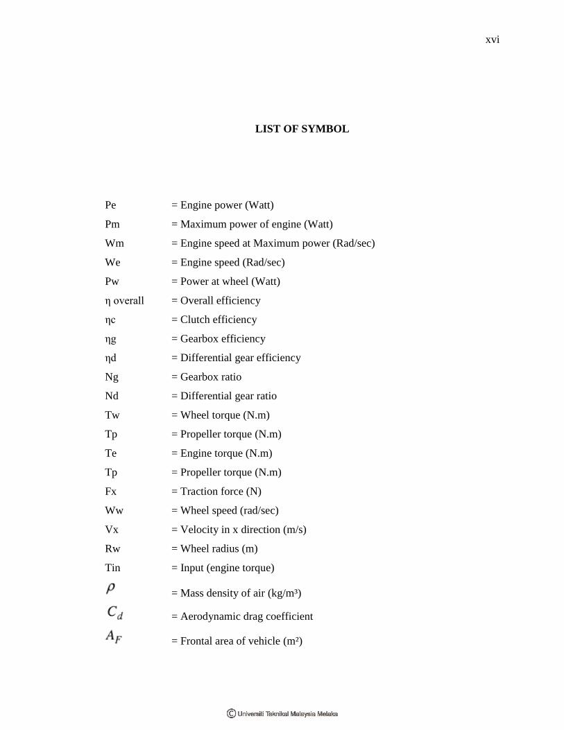
LIST OF SYMBOL
Pe = Engine power (Watt)
Pm = Maximum power of engine (Watt)
Wm = Engine speed at Maximum power (Rad/sec)
We = Engine speed (Rad/sec)
Pw = Power at wheel (Watt)
η overall = Overall efficiency
ηc = Clutch efficiency
ηg = Gearbox efficiency
ηd = Differential gear efficiency
Ng = Gearbox ratio
Nd = Differential gear ratio
Tw = Wheel torque (N.m)
Tp = Propeller torque (N.m)
Te = Engine torque (N.m)
Tp = Propeller torque (N.m)
Fx = Traction force (N)
Ww = Wheel speed (rad/sec)
Vx = Velocity in x direction (m/s)
Rw = Wheel radius (m)
Tin = Input (engine torque)
= Mass density of air (kg/m³)
= Aerodynamic drag coefficient
= Frontal area of vehicle (m²)
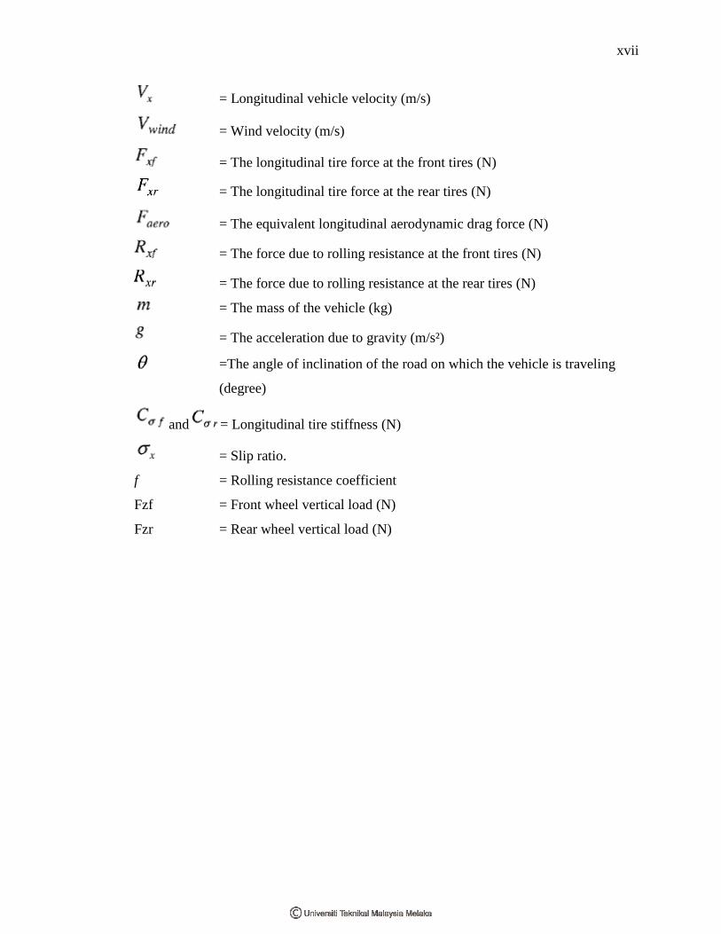
xvii
= Longitudinal vehicle velocity (m/s)
= Wind velocity (m/s)
= The longitudinal tire force at the front tires (N)
= The longitudinal tire force at the rear tires (N)
= The equivalent longitudinal aerodynamic drag force (N)
= The force due to rolling resistance at the front tires (N)
= The force due to rolling resistance at the rear tires (N)
= The mass of the vehicle (kg)
= The acceleration due to gravity (m/s²)
=The angle of inclination of the road on which the vehicle is traveling
(degree)
and = Longitudinal tire stiffness (N)
= Slip ratio.
f = Rolling resistance coefficient
Fzf = Front wheel vertical load (N)
Fzr = Rear wheel vertical load (N)
xviii
LIST OF APPENDIX
FIGURE TITLE PAGE
A Coefficient of Rolling Resistance 90
B Aerodynamic Resistance Coefficient 91
C Values of Aerodynamic Resistance Coefficient For 91
Various Type of Vehicle
D Proton Waja 1.6 Specification 92
1
CHAPTER I
INTRODUCTION
1.1 Project Introduction
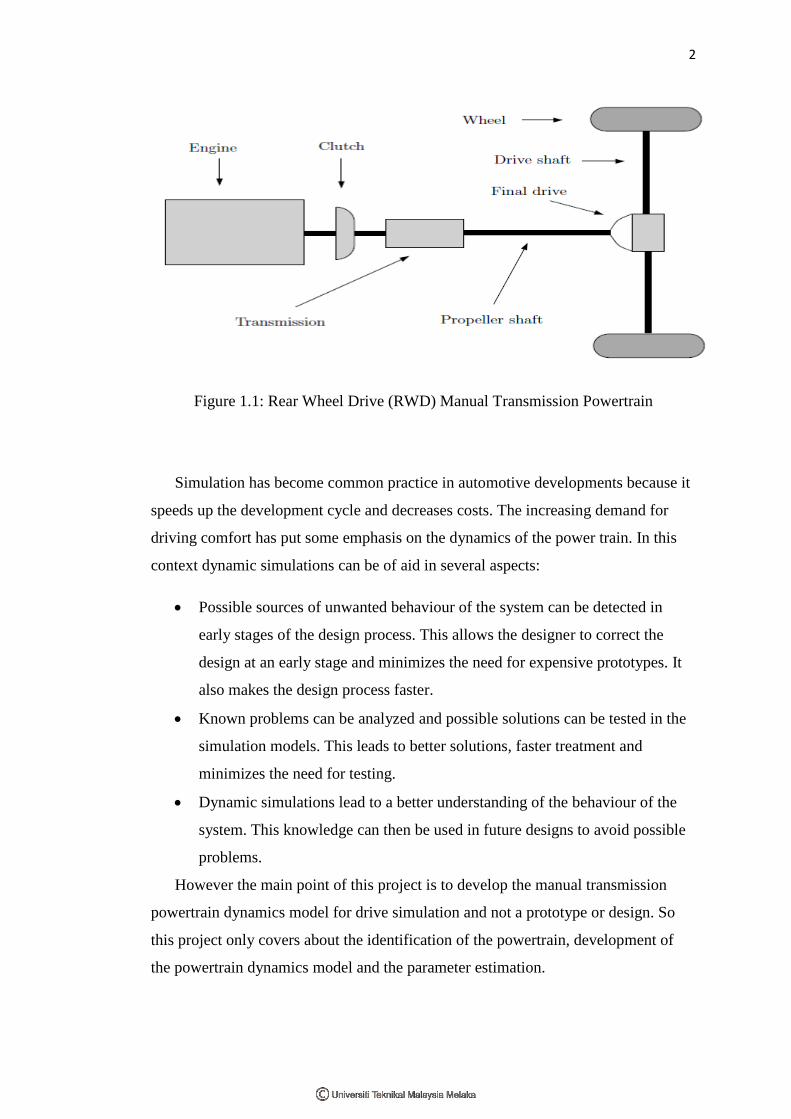
A manual transmission power train consists of engine and driveline. The
main parts of the driveline are clutch, transmission, shafts and wheels. The driveline
is a fundamental part of a vehicle and its dynamics has been modeled in different
ways depending on the purpose. In order to analyze and develop of manual
transmission power train dynamic (forces generated and the responses of the power
train), a model should be developed. From the manual transmission power train
dynamic model, a mathematical model will be developed. Then, with the
development of power train mathematical model, a simulation can be developed
using software like Mat Lab and Simulink. Finally the simulation will be using for
the drive simulator.
2
Figure 1.1: Rear Wheel Drive (RWD) Manual Transmission Powertrain
Simulation has become common practice in automotive developments because it
speeds up the development cycle and decreases costs. The increasing demand for
driving comfort has put some emphasis on the dynamics of the power train. In this
context dynamic simulations can be of aid in several aspects:
Possible sources of unwanted behaviour of the system can be detected in
early stages of the design process. This allows the designer to correct the
design at an early stage and minimizes the need for expensive prototypes. It
also makes the design process faster.
Known problems can be analyzed and possible solutions can be tested in the
simulation models. This leads to better solutions, faster treatment and
minimizes the need for testing.
Dynamic simulations lead to a better understanding of the behaviour of the
system. This knowledge can then be used in future designs to avoid possible
problems.
However the main point of this project is to develop the manual transmission
powertrain dynamics model for drive simulation and not a prototype or design. So
this project only covers about the identification of the powertrain, development of
the powertrain dynamics model and the parameter estimation.
3
1.2 Project Objective
To built a manual transmission powertrain dynamics model to be used in drive
simulator simulation and validation.
1.3 Problem Statement
To give the passions to the one who are driving the drive simulator, the simulation
must be look like the real one. In order to give the perfect simulation, the drive
simulator of manual transmission powertrain dynamics model is designed. With the
dynamics identification and parameter estimation given to the model, the result must
be very interesting.
1.4 Scope
Powertrain dynamics identification.
Develop powertrain dynamics model.
Parameters estimation.
4
CHAPTER II
LITERATURE REVIEW
In a vehicle, the term powertrain refers to the group of components that
generate power and deliver it to the road surface. This includes the engine,
transmission, driveshafts, differentials, and the final drive.
2.1 Engine
An engine is a mechanical device that produces some form of output from a
given input. The purpose of an engine is to produce mechanical power from a fuel
source. Originally an engine was a mechanical device that converted force into
motion. The purpose of a gasoline car engine is to convert gasoline into motion so
that your car can move. Currently the easiest way to create motion from gasoline is
to burn the gasoline inside an engine. Therefore, a car engine is an internal
combustion engine (combustion takes place internally).
The core of the engine is the cylinder, with the piston moving up and down
inside the cylinder. Most cars have more than one cylinder (four, six and eight
cylinders are common). In a multi-cylinder engine, the cylinders usually are arranged
in one of three ways. That are inline, V or flat (also known as horizontally opposed
or boxer), as shown in the following figures.


![Seat No. [4718]-201 - Savitribai Phule Pune Universitycollegecirculars.unipune.ac.in/sites/examdocs/AprilMay...[4718]-201 2 (b) Explain the concept of function overloading with suitable](https://img.pdfslide.us/doc/110x75/5a9f23ef7f8b9a84178c6dfc/pdfseat-no-4718-201-savitribai-phule-pune-univer-4718-201-2-b-explain.jpg)