Embed Size (px)
Citation preview
Manufa
cturi
ng &
Pro
duct
sP
roje
ct N
o.
PN
02.1
908 (
Par
t 1)
Development of Limit States
Design Method for Joints with
Dowel Type Fasteners
Part 1: Literature Review

© 2004 Forest & Wood Products Research & Development Corporation All rights reserved. Publication: Development of Limit States Design Method for Timber Joints with Dowel Type Fasteners Part 1 Literature Review The Forest and Wood Products Research and Development Corporation (“FWPRDC”) makes no warranties or assurances with respect to this publication including merchantability, fitness for purpose or otherwise. FWPRDC and all persons associated with it exclude all liability (including liability for negligence) in relation to any opinion, advice or information contained in this publication or for any consequences arising from the use of such opinion, advice or information. This work is copyright and protected under the Copyright Act 1968 (Cth). All material except the FWPRDC logo may be reproduced in whole or in part, provided that it is not sold or used for commercial benefit and its source (Forest and Wood Products Research and Development Corporation) is acknowledged. Reproduction or copying for other purposes, which is strictly reserved only for the owner or licensee of copyright under the Copyright Act, is prohibited without the prior written consent of the Forest and Wood Products Research and Development Corporation. Project no: PN02.1908 (Part 1) Researchers:
I. Smith, G.C. Foliente CSIRO Building, Construction and Engineering PO Box 56, Highett, Victoria 3190 Forest and Wood Products Research and Development Corporation PO Box 69, World Trade Centre, Victoria 8005 Phone: 03 9614 7544 Fax: 03 9614 6822 Email: [email protected] Web: www.fwprdc.org.au
Development of Limit States Design Method for Joints with Dowel Type Fasteners
Literature Review
Prepared for the
Forest & Wood Products Research & Development Corporation
by
G. Foliente I. Smith
The FWPRDC is jointly funded by the Australian forest and wood products industry and the Australian Government.
3
Contents EXECUTIVE SUMMARY 4 INTRODUCTION 6
Background 6 Elements of a Joint Design Method 7
REVIEW OF JOINT DESIGN STANDARDS 9
Introduction 9 Australian Code 11 US Code 15 Canadian Code 23 European Code 28 Summary of Issues 33
RECOMMENDATIONS 35
General 35 Factors and Parameters to Consider 36
REFERENCES 38 APPENDIX A. The European Yield Model 44 APPENDIX B. Analysis of Stringer�s (1991) Results 47 APPENDIX C. Notations 50

4
Executive Summary In this project, we aim to develop a limit states design procedure for timber joints. Towards
this goal, we reviewed the current Australian practice, and the design codes in the USA,
Canada and Europe, and identified the issues and parameters that need to be considered in
an experimental program aimed at evaluating the use of the European Yield Model (EYM)
for joints with dowel-type fasteners. We also reviewed the previous research by Stringer
(1991) investigating the use of EYM for nailed joints with Australian timbers; Appendix B
provides a commentary and re-analysis of his data.
In Phase 2, we will conduct a focused experimental program, after consultation with PRI.
With promising results, we will then prepare a draft design procedure in Phase 3 and submit
a set of recommendations on required data and activities for full implementation. Before
presenting the recommended design procedure, the draft procedure will be trialed in the field
by selected practicing engineers. Their comments and recommendations will be taken into
account in revising or refining the design procedure.
Based on the review of literature and design standards here and overseas, our primary
recommendation is to fully develop the use of EYM for the design of dowel-type fasteners in
Australia. As a first step, we should consider nails, and, possibly, slender bolts. This process
will involve developing:
! an experimental program to establish properties and apply the EYM concept to a
range of variables common in Australian condition; and
! the infrastructure required to support the use of this design procedure.
The latter will include development of guidelines and/or standards to determine the input
properties needed in EYM-based design. Despite the amount of development and data
available from other countries, a fair amount of work still needs to be done to evaluate its
applicability to a wide range of Australian joints with dowel-type fasteners, and to introduce
simplifications to make the proposed design procedures easier to use.
In developing LSD procedures for timber joints, we need to determine the appropriate
resistance factors, develop a method to estimate joint variability based only on data from
fastener and timber components of the joint, and conduct reliability analysis to calibrate the
method to accepted levels of performance.

5
We also recommend further development of the standard for testing whole joint systems
under realistic loading conditions; this is currently in draft form as AS/NZS BBBB. The
concept is state-of-the-art, and many aspects of this suite of standards provide typically
missing elements (evident in the review of overseas codes) that are needed to support
design procedures for timber joints.

6
Introduction
Background
The new Timber Structures Code AS 1720.1 (SAA 1997) provides a limit states design
(LSD) procedure for timber construction. Although the original intent was to do only a �soft
conversion� from the previous version (SAA 1988), some revisions were nevertheless
included to reflect new data and information that have been generated or obtained from
timber testing and research since 1988. The code provisions for connections, however, have
only been soft-converted to LSD format.
The National Timber Framing Code AS 1684 (SAA 1999), which has been providing
�deemed to comply� provisions for timber construction since 1975, has also been revised to
reflect new timber engineering technology, following the new LSD code. The new suite of
framing standards (now in four volumes) caters for a widening variety of wood-based
materials and evolving design conditions. The framing standards incorporated results of an
experimental program conducted at CSIRO (Foliente et al. 1996) to address the lack of
knowledge associated with joints that are widely used throughout the domestic construction
industry but are currently not adequately covered by AS 1720.1, and for which conventional
code design procedures cannot be applied.
Since the new AS 1684 framing tables were generated following the provisions of AS
1720.1, a timber building constructed following the new AS 1684 framing tables can be said
to be �engineered�. For timber members, this is true; but for the joints and connections in that
building, this is not the case. All the engineering design spent on getting the right member
sizes and spans may be for naught because if the building is subjected to extreme loads, the
joints could fail and the structure could be severely damaged.
Joint systems are typically one of the most critical components of any structure. They can
govern the overall strength and serviceability of structural systems, and should be given
primary considerations in designing or detailing for durability and fire resistance.
Assessments of timber buildings damaged after extreme wind and earthquake events often
point to inadequate connections as the primary cause of damage (Foliente 1998). Because
of the importance of joints in the overall performance of buildings, it is often said that:
�A structure is a constructed assembly of joints separated by members.�
7
In this project, we aim to develop a limit states design procedure for timber joints. Towards
this goal, we planned to revisit the current Australian practice, review the design practice in
North America and Europe, and plan an experimental program to evaluate the use of the
European Yield Model (EYM) for joints with dowel-type fasteners. With promising results, we
will then prepare a draft design procedure and submit a set of recommendations on required
data and activities for full implementation. Before presenting the recommended design
procedure, the draft procedure will be trialed in the field by selected practicing engineers.
Their comments and recommendations will be taken into account in revising or refining the
design procedure.
This report covers the review of Australian and overseas practice, and includes general
recommendations on the scope of the experimental program proposed for the next phase of
the project.
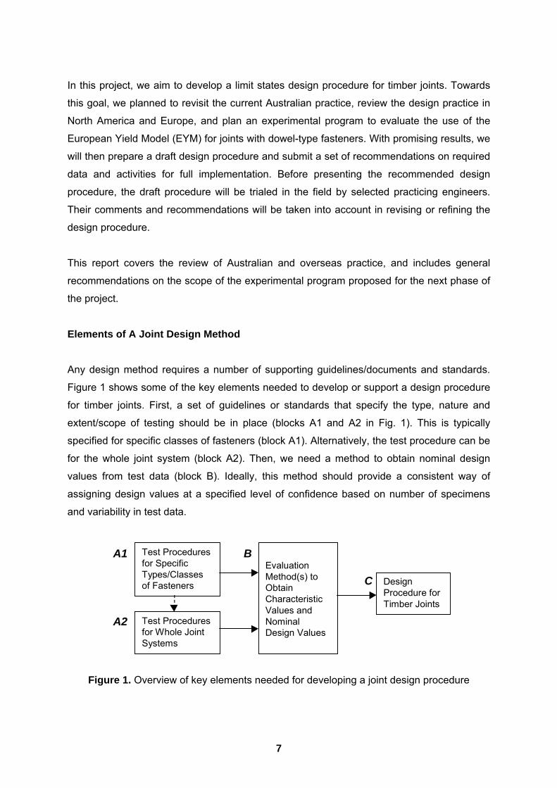
Elements of A Joint Design Method Any design method requires a number of supporting guidelines/documents and standards.
Figure 1 shows some of the key elements needed to develop or support a design procedure
for timber joints. First, a set of guidelines or standards that specify the type, nature and
extent/scope of testing should be in place (blocks A1 and A2 in Fig. 1). This is typically
specified for specific classes of fasteners (block A1). Alternatively, the test procedure can be
for the whole joint system (block A2). Then, we need a method to obtain nominal design
values from test data (block B). Ideally, this method should provide a consistent way of
assigning design values at a specified level of confidence based on number of specimens
and variability in test data.
DesignProcedure forTimber Joints
EvaluationMethod(s) toObtainCharacteristicValues andNominalDesign Values
Test Proceduresfor SpecificTypes/Classesof Fasteners
Test Proceduresfor Whole JointSystems
A1
A2
B
C
Figure 1. Overview of key elements needed for developing a joint design procedure

8
The two testing procedures in blocks A1 and A2 (Fig. 1) are complementary. Test
procedures for whole joint systems can be used to establish the design properties and/or
evaluate the performance of a specific joint system under single or combined loads. These
can also be used for individual fastener types (e.g. nails, bolts, screws, etc.) but they are
most useful for jointing systems (i.e. complete joint system of similar or mixed materials) to:
• assess the performance and allocate design properties of a joint system under a specific
loading configuration
• assess design theories for joint systems (e.g., block C)
In the following section, the review of different LSD design procedures for timber joints in
selected countries/regions of the world will cover relevant information related to each block
in Fig. 1. Primary supporting documents and standards are cited.
9
Review of Joint Design Standards
Introduction
Overview
The purpose of this section is to review the existing joint design standards in selected
countries/regions of the world where timber engineering technology is well developed and
where engineering practice is well recognised. Only a brief overview of the Australian code
provisions is given, but extensive comments are made. The review of overseas codes is
more detailed but focused heavily on dowel-type fasteners because these are the most
common in timber construction. The presentation covers critical elements of the design
method development process (Fig. 1), and includes specific comments that may be relevant
to this project. Primary supporting documents and standards are included. The most
important issues that need to be considered in the development of a new LSD method for
timber joints are summarised.
Types of Joints
Joints will be categorised as those with (Madsen 1998):
• dowel type fasteners, and
• surface connections.
Dowel type fasteners include drift pins, bolts, coach screws (called lag screws in North
America), wood screws, nails, spikes and timber rivets (also known as glulam rivets). Coach
screws are a relatively large and special type of wood screw, and normally used in steel-to-
wood connections. Timber rivets are a special type of nail for making single shear steel-to-
wood splice joints. With the exception of the timber rivets, dowel type fasteners almost
always have a nominally circular cross-section. Nails, spikes and timber rivets are typically
installed without a lead-hole by hammering or using an air gun. Screws and coach screws
are installed in lead holes. Drift pins (plain dowels) are installed by hammer into holes of the
same nominal diameter. Bolts are installed in oversize holes. Typically the hole is made
with a drill 1 to 2 mm greater than the bolt shank diameter. Bolts always have a head and
nut, and washers beneath either the head or nut if they bear onto the face of a timber
member. Literature is occasionally confusing because some authors from mainland Europe
use the term bolt when they mean a plain dowel. All types of dowel fastener are permitted in
applications where they resist loads by bending action (referred to as lateral loading because
force from the members is applied perpendicular to the axis of the fastener). All types other
10
than drift pins are permitted in applications where they resist forces along the axis (referred
to as axial loading, or withdrawal loading in the case of nails and screws). Axial force
resistance capabilities of nails, wood screws and lag-screws are relatively unreliable, and so
withdrawal resistance can only be utilised for load combinations of �lesser� cumulative
duration (e.g. wind or earthquake loads in Canada).
Surface, or skin, connections include those made using �shear-plate� and �split-ring�
connectors, which were developed in the USA in the mid-1930s. Shear-plates are used in
timber-to-timber or steel-to-timber joints, while split-ring connectors are used in timber-to-
timber joints. Both types of connector are used in conjunction with a bolt (or coach screw)
which passes through the centre. For split-rings the function of the bolt is to prevent
separation of the members so they do not �work themselves� off the rings. A split-ring is
embedded in both members and bridges the joint plane. It transfers all force across the
joint. Shear-plates locally increase the fastener diameter, and therefore the capacity. One is
placed either side of a joint plane in a wood-to-wood joint, but they do not bridge the joint
plane. They transfer the force to the bolt passing through them, and it must be capable of
resisting the full joint load in shear. Manufacture of joints with either type of connector is
labour intensive. Both types are only suitable for use with large dimension timbers. In parts
of Europe �toothed plate� connectors are used. This is for all intents a low capacity type of
shear-plate connector, but is much less labour intensive to install and can be used with small
dimension timber (lumber). Punched metal plate connectors and various folded plate
connectors manufactured from light gauge steel plate are used to make lumber-to-lumber
joints. Punched metal plate connectors can have integral teeth or are fastened to the lumber
with nails. Folded plate connectors are fastened to the lumber with nails. Punched metal
and folded plate connectors are typically proprietary products, i.e., they are not
manufactured to a standardised form.
Not all types of fasteners and connectors mentioned are covered by the structural design
standards of various countries. Design capacities of proprietary products usually fall outside
the scope of written codes. This does not mean that they cannot be used for building
purposes. All developed countries have some sort of deemed to comply specifications for
small to medium size timber buildings, and a process of certification of products.
Certification often includes recommended design capacities that engineers can use.
Site-made glued joints are usually excluded from engineering design codes, because of
concern about the ability of �workers� to apply proper quality control on the �job site�. There

11
are exceptions to this, e.g., in Germany on-site manufacture of large finger joints in glued-
laminated-timbers is permitted. Glued joints are used extensively in the manufacture of
engineered wood components, but this is dealt with via written product standards or product
certification, and not design codes.
Australian Code
Overview of Design Method
To design timber joints, an engineer typically needs only the Timber Structures Code AS
1720.1 (SAA 1997), which gives him/her the design equations, capacities and modification
factors to use. Design provisions include the following:
• Nailed joints,
• Screwed joints,
• Bolted joints,
• Coach screwed joints, and
• Shear-plate fastener joints.
Applications of these provisions to design situations are demonstrated in the Timber Design
Handbook (Boughton and Crews 1998).
The new LSD code for joint design has the following generic format:
(�Nj) ≥ N*
where
(�Nj) = �k1 � kj n Qk
and
N* = factored design action effect
� = capacity factor
ki = modification factor
n = number of fasteners
Qk = characteristic capacity of a fastener
Timber density groups classify joint capacities. As in most other codes elsewhere, the
duration of load factor follows the �Madison curve� (Wood 1951).
Technical Basis
Australian joint design procedures are, to a large degree, derived from early North American
studies (e.g., Trayer 1932). This was supplemented by studies on Australian timbers,

12
particularly hardwoods, and local practice and conditions. Key contributors to this
development include Langlands and Thomas (1939), the Department of Works and Housing
(1946), Pearson (1965, Pearson et al. 1958), Mack (1966, 1978, 1979) and Lhuede (1986,
1988). The current design provisions are primarily due to the work of former CSIRO
researchers, J.J. Mack and E.P. Lhuede. Leicester (1993) has provided a brief overview of
timber joint code development in Australia.
The joint design provisions of the code are based solely on an empirical fit of test data. Since
these provisions in the current LSD AS 1720.1 are essentially the same as in the previous
version of the code, the commentary by Lhuede (1988) on the latter is still very relevant.
There has been some interest in Australia in the use of the European Yield Model (EYM) for
dowel-type fasteners for some time. (This model is discussed in later sections of the report;
Appendix A has a set of equations that describe the model). Mack (1960, 1962) investigated
this first, followed by Lhuede (1988, 1990) and then by Stringer (1991, 1993). Stringer�s work
and results are discussed under Comments and in Appendix B.
Supporting Standards
The following standards provide support and information needed to use the design
procedures. In Fig. 2, they are placed in the context of the diagram given in Fig. 1.
• AS 1720.1 � 1997. Timber Structures, Part 1: Design methods. Standards Australia, The
Crescent, Homebush, NSW.
• AS 1649 � 1998. Timber � Methods of test for mechanical fasteners and connectors �
Basic working loads and characteristic strengths. Standards Australia, The Crescent,
Homebush, NSW.
• AS/NZS BBBB (Committee Draft). Timber � Methods for evaluation of mechanical joint
systems, Part 1: Static loading; Part 2: Cyclonic wind loading; Part 3: Earthquake
loading. Standards Australia, The Crescent, Homebush, NSW.
13
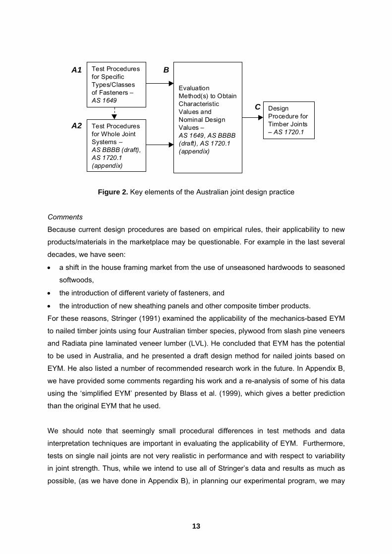
Figure 2. Key elements of the Australian joint design practice
Comments
Because current design procedures are based on empirical rules, their applicability to new
products/materials in the marketplace may be questionable. For example in the last several
decades, we have seen:
• a shift in the house framing market from the use of unseasoned hardwoods to seasoned
softwoods,
• the introduction of different variety of fasteners, and
• the introduction of new sheathing panels and other composite timber products.
For these reasons, Stringer (1991) examined the applicability of the mechanics-based EYM
to nailed timber joints using four Australian timber species, plywood from slash pine veneers
and Radiata pine laminated veneer lumber (LVL). He concluded that EYM has the potential
to be used in Australia, and he presented a draft design method for nailed joints based on
EYM. He also listed a number of recommended research work in the future. In Appendix B,
we have provided some comments regarding his work and a re-analysis of some of his data
using the �simplified EYM� presented by Blass et al. (1999), which gives a better prediction
than the original EYM that he used.
We should note that seemingly small procedural differences in test methods and data
interpretation techniques are important in evaluating the applicability of EYM. Furthermore,
tests on single nail joints are not very realistic in performance and with respect to variability
in joint strength. Thus, while we intend to use all of Stringer�s data and results as much as
possible, (as we have done in Appendix B), in planning our experimental program, we may
DesignProcedure forTimber Joints� AS 1720.1
EvaluationMethod(s) to ObtainCharacteristicValues andNominal DesignValues �AS 1649, AS BBBB(draft), AS 1720.1(appendix)
Test Proceduresfor SpecificTypes/Classesof Fasteners �AS 1649
Test Proceduresfor Whole JointSystems �AS BBBB (draft),AS 1720.1(appendix)
A1
A2
B
C
14
also re-work some of Stringer�s tests, as we consider other factors that may affect the use of
EYM in Australia.
Based on Fig. 2, it would seem that current support for the design of joints in AS 1720.1
through existing and draft standards is adequate. But before AS/NZS BBBB was drafted, the
need for better and more realistic joint testing and evaluation procedures was highlighted
(Leicester 1993). There were three primary problems with the previous operational system
(Foliente and Leicester 1996):
• First, the AS 1649 test provides data on only one type of failure mode whereas at least
ten types of failure modes have been observed in laboratory tests. Some examples
include:
! failure of metal (tension, bending, shear, buckling),
! failure of wood parallel to the grain (tension, compression, shear), and
! failure of wood perpendicular to the grain (tension, compression).
An example of major concern is the failure of bolted joints due to splitting; AS 1649 does
not address the problem of splitting.
• The second flaw is that the load factors currently used in AS 1649 are questionable.
They were derived on the basis of fitting existing practice. It is not known whether the
controlling criteria, then in use, were related to strength or serviceability (deformation);
also the load factors vary considerably from one connector type to another for no obvious
reasons.
• The third flaw in the current procedure arises from the fact that there are very few
theories to predict the strength of joint systems on the basis of the characterisation of
single connectors. Thus, there is obviously a need for a standard not only to describe the
testing of new fasteners, but also for whole joint systems.
The draft standard AS/NZS BBBB is a set of standards for evaluating complete joint systems
that:
• specifies actual in-service joint configuration;
• specifies realistic in-service loads;
• has a consistent method of obtaining characteristic strength; and
• has a consistent method of applying load factors to obtain joint design properties.
The spirit of this set of joint systems standard is analogous to AS 4063 Timber�Stress-
graded�In-grade Strength and Stiffness Evaluation (SAA 1992), i.e., it may be used to test
any joint under any loading configuration but it is not necessary to test every joint under
15
every loading configuration. Additional information about this set of standards can be found
in Foliente and Leicester (1996), and Foliente et al. (1998).
With regards to the method of establishing characteristic values and nominal design values
(block B in Fig. 2), AS BBBB uses the proposal by Leicester (1986). Bryant and Hunt (1999)
conducted recently a numerical study using Monte Carlo simulation to evaluate different
methods of computing characteristic values of joints. Since the �Leicester method� provided
good predictions for reasonable sample sizes, they recommended its use, especially where
the coefficient of variation is calculated from the lower tail of experimental results. It should
be noted that the Leicester method was derived with the latter in mind; it is conservative
when the coefficient of variation is calculated from all the test data.
US Code
Overview of Design Methods
A vast majority of American engineers design timber structures based on the Working Stress
Design (WSD) approach. The factor of safety is 1.3 for members loaded in bending, tension
and compression (Madsen 1992). For timber joints the factor of safety is inconsistent across
various types of joints, and cannot actually be defined. The approach for splice joints with
dowel type fasteners is to take the allowable load as a fraction of the load at the �proportional
limit� load or an approximation to it (USDA 1987). For joints made with split-ring or shear-
plate connectors the allowable load is based on consideration of both the peak load and
proportional limit load. The proportional limit load, as observed in a short-term monotonic
loading test, has traditionally been believed to be the point at which irreversible damage
processes begin. If observations of joint slip (relative displacement of adjacent members at
the joint location) are made using modern high resolution Linear Variable Displacement
Transformers (LVDT�s), and these are placed in such a way that all member deformation is
excluded, load versus slip relationships are much more curvaceous than was thought.
Existence of a proportional limit is largely an illusion and reflects use of low precision
methods such as manually read dial gauges (Smith 1998). Withdrawal capacities of nails,
wood screws and coach screws are based on peak load. Peak loads are multiplied by
fractions to account for safety, variability and moisture effects (USDA 1987). The fraction of
peak load used varies between types of fasteners.
16
Unadjusted allowable loads apply to a single fastener/connector subjected to normal
duration (10 year) loading, and a dry service condition. Deviations from reference conditions
are accounted for by a sequence of modification factors. Concepts and much of the data
that underpin working stress design of joints are the result of research at the US Forest
Products Laboratory in the 1930s and 1940s (e.g., Trayer 1932). It is generally accepted
that the working stress method embodies inconsistencies in capacities for different types of
fasteners (McLain 1993). For most types of mechanical joint the ultimate (peak) load lies
well above the estimated proportional limit load. The ratio of ultimate to proportional limit
load can approach 3.5 for nailed softwood joints and 7.0 for hardwood joints (USDA 1987).
Thus, the allowable load for a joint is often only a small fraction of its ultimate strength.
Joints tend to be strong elements within structural systems. Overloading will therefore tend
to cause failures in members rather than joints.
There have been some relatively recent changes in the basis of US design provisions for
joints, especially with regard to dowel type fasteners (AFPA 1991). One important change is
that the lateral load capacities of dowel type fastener joints are now based on Johansen�s
yield model (Johansen 1949, Larsen 1979). The model presumes that both the fastener and
the wood foundation upon which it bears behave as ideal rigid plastic materials, and
therefore that the yield and ultimate capacities coincide. The basis of the theory is exactly
the same as for the well-known limit analysis (plastic design) theory applied to steel frames.
The Johansen theory is often referred to as the European Yield Model (EYM) in the USA.
The most recent working stress design code National Design Specification for Wood
Construction was published in 1997 (AFPA 1997). Specific provisions and their basis are
discussed in the next section of this report.
Another important change is that, for load combinations including short-duration loads such
as wind or earthquake, NDS now prescribes a load duration factor of 1.6 for all connections.
However, the Uniform Building Code (UBC) (ICBO 1997) prescribes different load duration
factors for joints with dowel-type fasteners under these loading conditions. The UBC permits
a load duration factor of 1.6 for joints exhibiting failure modes III or IV, but a load duration
factor of 1.33 must be used for joints that exhibit yield modes I or II. The reason for this
requirement is that there are available data that demonstrate that modes III or IV joints have
sufficient ductility under cyclic loading (Dolan et al. 1995, 1996) but there is a lack of data for
modes I or II joints. The NDS provides the designer with multiple tables containing capacities
for common connections but yield modes are not identified. Thus, the designer must carry
out potentially cumbersome calculations first simply to determine the governing yield mode

17
before he/she can apply the appropriate UBC load duration factor. To address this issue,
Tucker et al. (2000) have produced tables that extend NDS tables to contain connection
capacities and yield modes to accelerate the design process.
The American Society of Civil Engineers (ASCE) recently published a code for limit states
design of timber construction (ASCE 1996a). This is based on a partial-coefficient approach
that in the USA is known as Load and Resistance Factor Design (LRFD). Technically this is
equivalent to many other, and somewhat older, limit states design partial-coefficient design
codes. As in other countries, partial factors are assigned based on committee judgement
aided by structural reliability analysis. It is not clear to what extent the ASCE code is actually
used by design engineers. Use of any design code becomes mandatory once it is
referenced in the building code for a political jurisdiction. Most jurisdictions are regional and
adopt one of several �model� building codes, e.g., Uniform Building Code. Some large cities
have their own building codes. Building codes reference both WSD and LRFD methods (or
just WSD if they have not recently been updated). Normally the two methods are not mixed
in design of any one structure, but the practice is permitted in California and some other
states. Eventually the WSD should cease to be referenced and therefore disappear from
use, but informal comments from colleagues in the USA imply that at present very limited
use is made of LRFD.
Common connections are those made using nails, bolts, screws, punched metal plate
connectors, folded plate connectors, and hangers. Of these types, only capacities of those
made with generic fasteners (nails, bolts and screws) are dealt with by design codes. Thus,
only use of generic dowel type fasteners is discussed further.
Technical Basis
The research background and rationale underpinning much of the US code provisions have
been discussed by McLain (1984) and in a recent ASCE publication entitled Mechanical
Connections in Wood Structures (ASCE Manuals and Reports on Engineering Practice No.
84) (ASCE 1996b). The latter covers the following:
• Nails, spikes and staples,
• Lag (or coach) screws and wood screws,
• Bolts, drift bolts and pins,
• Metal connector plates, and
• Timber connectors (e.g., shear-plate and split ring connectors).
18
For each fastener type, the ASCE manual also contains sections on details, fabrication and
installation practices, and a brief review of �foreign� design practices or specifications. We
recommend those interested in background technical details to consult the ASCE manual. In
the rest of this section, we focus the discussion on laterally loaded fasteners.
Yield limit load (or EYM) equations for bolt, coach screw, wood screw, nail, spike and drift-
pin joints are given in the National Design Specification for Wood Construction (AFPA 1997).
The approach was first adopted in the 1991 edition of that Specification (AFPA 1991), at
which time it had been decided that mechanics-based formulae are the most rational means
of allowing designers to account for the many arrangement specific parameters that affect
the capacity of a joint (McLain 1993).
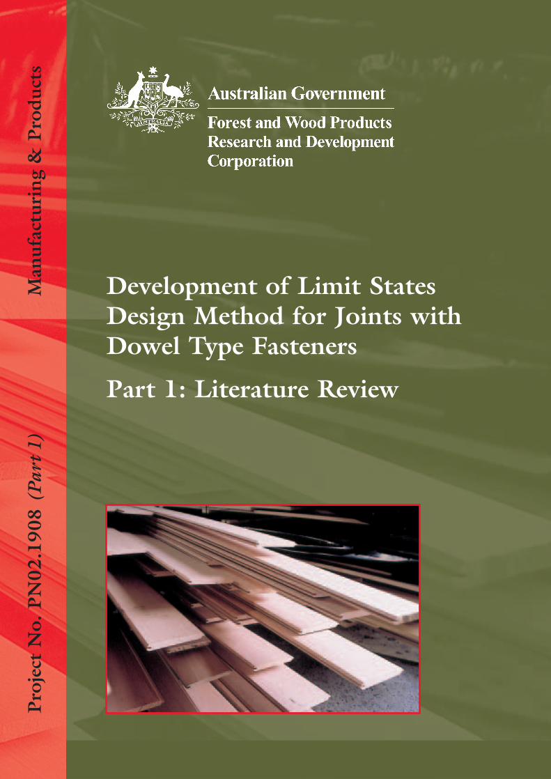
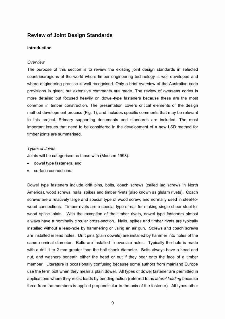
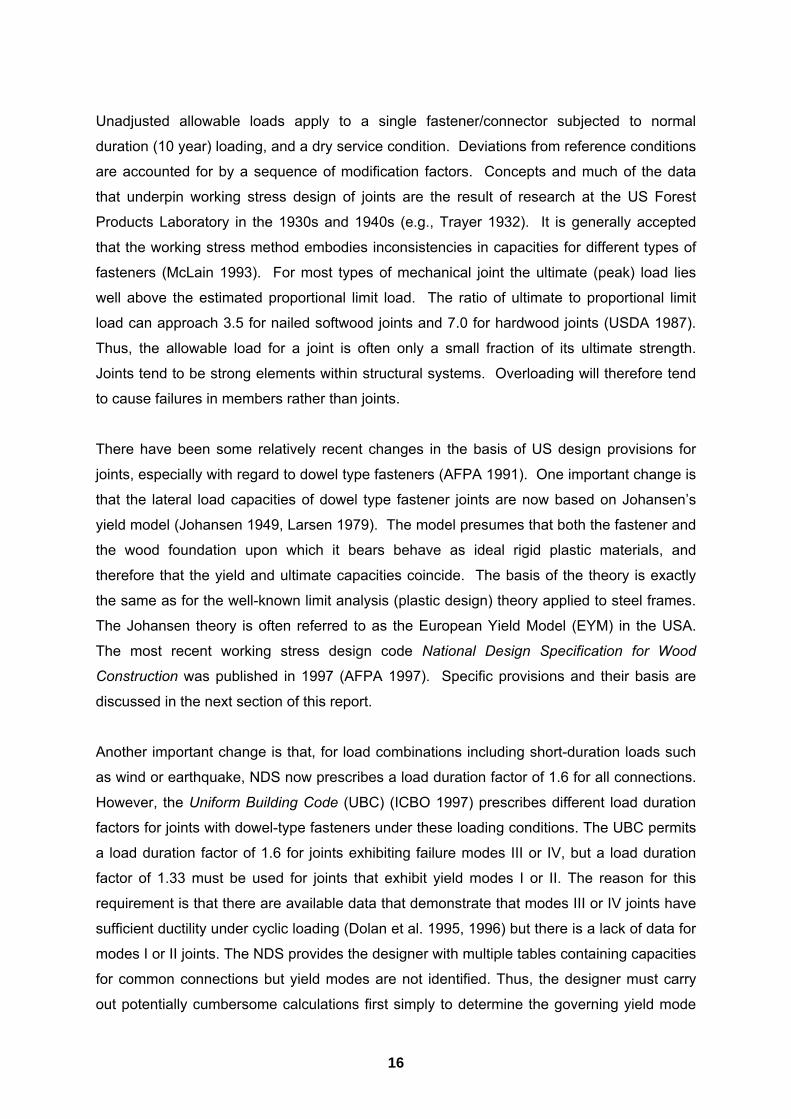
The yield limit load equations are a generalised form of the original EYM by Johansen
(1949). Figure 3 shows the failure modes that are possible for a single fastener joint loaded
in single shear (two-member arrangement). For the purposes of this report, the left member
is the head-side member and the right member the point-side member for joints with nails,
spikes, wood screws or coach screws. Comparable modes are applicable to multiple shear
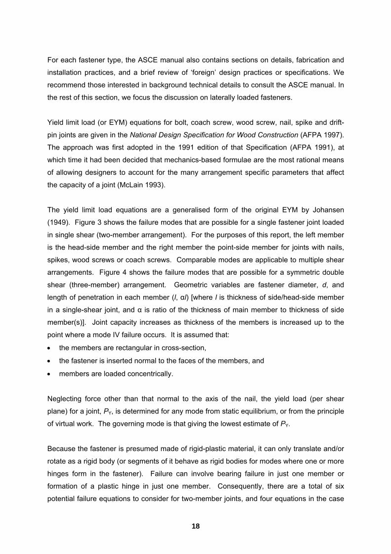
arrangements. Figure 4 shows the failure modes that are possible for a symmetric double
shear (three-member) arrangement. Geometric variables are fastener diameter, d, and
length of penetration in each member (l, αl) [where l is thickness of side/head-side member
in a single-shear joint, and α is ratio of the thickness of main member to thickness of side
member(s)]. Joint capacity increases as thickness of the members is increased up to the
point where a mode IV failure occurs. It is assumed that:
• the members are rectangular in cross-section,
• the fastener is inserted normal to the faces of the members, and
• members are loaded concentrically.
Neglecting force other than that normal to the axis of the nail, the yield load (per shear
plane) for a joint, PY, is determined for any mode from static equilibrium, or from the principle
of virtual work. The governing mode is that giving the lowest estimate of PY.
Because the fastener is presumed made of rigid-plastic material, it can only translate and/or
rotate as a rigid body (or segments of it behave as rigid bodies for modes where one or more
hinges form in the fastener). Failure can involve bearing failure in just one member or
formation of a plastic hinge in just one member. Consequently, there are a total of six
potential failure equations to consider for two-member joints, and four equations in the case
19
of three-member joints. The NDS equations (AFPA 1997) are based are those of �Original
EYM� (Appendix A), although the notation differs from that used here.
Figure 3. Yield modes for two-member joints
Figure 4. Yield modes for three-member joints
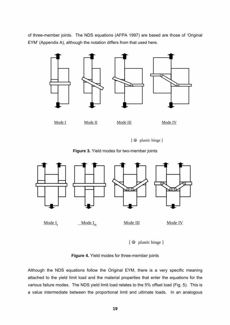
Although the NDS equations follow the Original EYM, there is a very specific meaning
attached to the yield limit load and the material properties that enter the equations for the
various failure modes. The NDS yield limit load relates to the 5% offset load (Fig. 5). This is
a value intermediate between the proportional limit and ultimate loads. In an analogous
Mode IVMode IIIMode IIMode I
[ plastic hinge ]
Mode IVMode III Mode ImMode Is
[ plastic hinge ]
20
manner, the bearing embedment (bearing) strength of the wood beneath a fastener and the
yield moment for the fastener foundation are 5% offset values. The product of the
calculations yields the nominal capacity for a joint with one fastener, i.e., they are values that
have not been modified for design purposes.
Figure 5. Five percent offset method for defining joint yield load (based on McLain 1993)
The nominal design value for a given combination of fastener and member parameters is
divided by applicable reduction terms. Reduction terms differ depending upon the type of
fastener. For bolts, drift pins and coach screws they are a function of the EYM mode that
governs (which reflects the slenderness of the fastener), and the maximum angle to the
grain at which the fastener loads any wooden member. For nails, spikes and wood screws
the reduction factor accounts only for the duration of the loading and depends upon the
fastener shank diameter. In the NDS, the reduction terms are incorporated directly into the
denominator of the �yield limit� equations. The purpose of these adjustments is to give
capacities that are representative of nominal proportional limit based design capacities in
earlier editions of the specification (soft calibration).
Material properties which are input to the yield limit equations reflect the type of fastener, its
size, the materials from which members are made and the direction to the grain at which
wood members are loaded. Embedment strength was determined according to the
procedures that have since been formalised in ASTM D 5764 (ASTM 1997a). Embedment
strength is taken as a function of fastener type, wood density, and direction of loading
relative to the grain in the case of larger diameter fasteners. Embedment properties are
available for steel and concrete as well as wood. Fastener bending strengths were
estimated based on ASTM F 1575 (ASTM 1995b), the tensile strength according to ASTM
Deformation (slip)
Load
5% fastener diameter
Yield Load

21
F606 (ASTM 1995a) or from tabulated tensile values. Methods of conversion have been
established for calculating the 5% offset bending strength from more readily available tensile
strength information (AFPA 1999).
In deriving NDS values no allowance was made for the possibility that presence of, for
example, a nail head or head of a bolt and the washer underneath it that might restrain the
end of and a fastener. Any restraint to the end(s) of a fastener will increase its capacity
unless members are thick enough to develop a mode IV failure. Similarly, no allowance was
made for friction between members which also enhances the capacity of a joint. Influences
such as those mentioned are ignored because they can not be reliably obtained in practice.
For slender and relatively flexible fasteners such as nails or screws, it is presumed that the
capacity of a joint is linearly proportional to the number of nails. This is generally regarded
as a reasonable assumption at loads approaching the ultimate capacity (Smith 1998).
However for joints having a number of bolts, drift pins or coach screws arranged in a row
parallel to the direction of the load there is an uneven distribution of force between the
fasteners. This promotes premature failure because, when a first fastener reaches its
capacity (local failure) the other fasteners usually cannot accommodate the redistributed
force, triggering an unstable unzipping in-the-row (Tan and Smith 1999). Adjustment factors
allowing for this are based on a simplified analogue where an assemblage of linear elastic
springs represents the fasteners and member segments between them (Lantos 1967,
Cramer 1968). For design purposes the number of fasteners adjustment factor depends
upon the tpe of fastener, their spacing and cross-section sizes of the joined members. The
approach can be manipulated to yield an explicit prediction of the effective loss in capacity,
per fastener, as a function of the number that are placed in a row (Zahn 1991).
The NDS requires that certain minimum requirements be met with regard to the arrangement
of fasteners in a joint, so as to reduce the possibility of premature brittle failure due to
splitting of wood members. Adjustments must be made to �basic� NDS capacities accounting
for the effects of non-reference moisture and duration of loading conditions.
Supporting Standards
The following standards provide support and information needed to use the design
procedures. In Fig. 6, they are placed in the context of the diagram given in Fig. 1.
• ASCE 16-95. Standard for load and resistance factor design for engineered wood
construction. American Society of Civil Engineers, New York, NY.
22
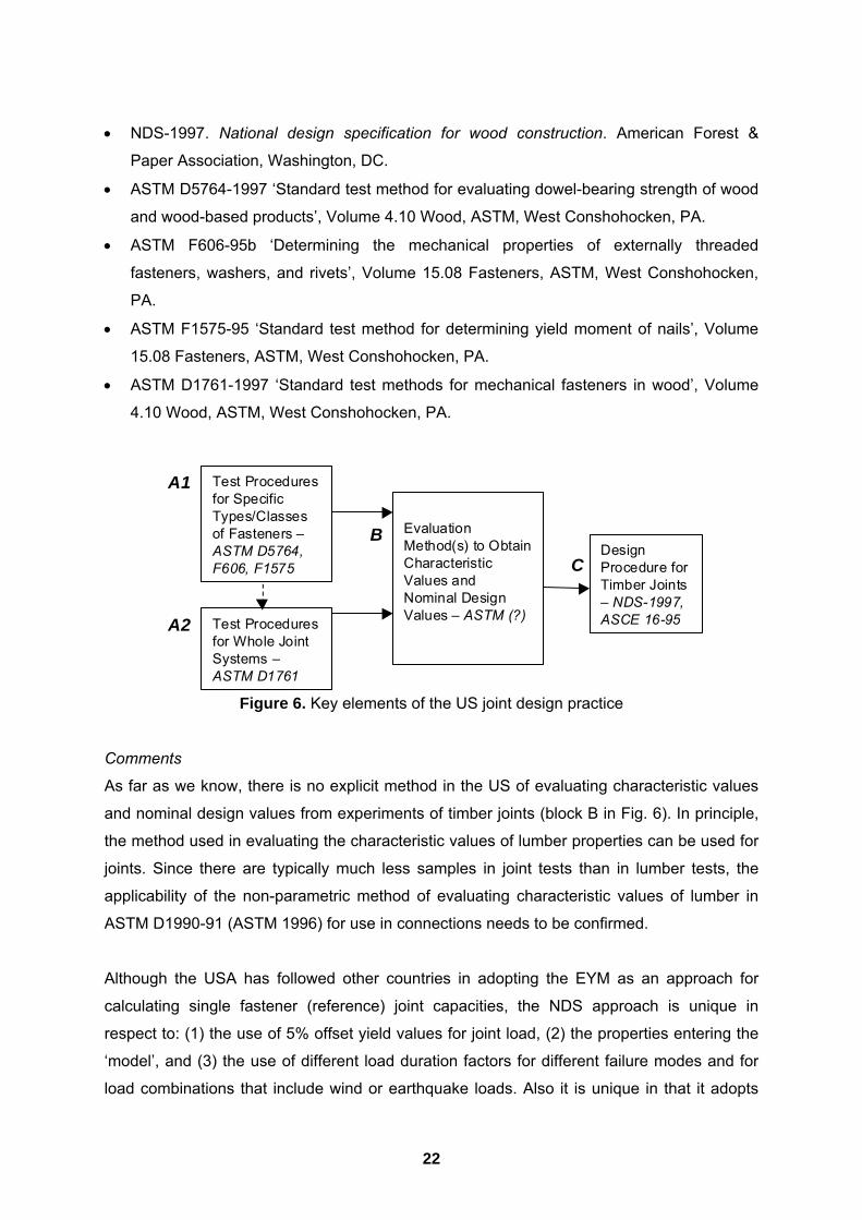
• NDS-1997. National design specification for wood construction. American Forest &
Paper Association, Washington, DC.
• ASTM D5764-1997 �Standard test method for evaluating dowel-bearing strength of wood
and wood-based products�, Volume 4.10 Wood, ASTM, West Conshohocken, PA.
• ASTM F606-95b �Determining the mechanical properties of externally threaded
fasteners, washers, and rivets�, Volume 15.08 Fasteners, ASTM, West Conshohocken,
PA.
• ASTM F1575-95 �Standard test method for determining yield moment of nails�, Volume
15.08 Fasteners, ASTM, West Conshohocken, PA.
• ASTM D1761-1997 �Standard test methods for mechanical fasteners in wood�, Volume
4.10 Wood, ASTM, West Conshohocken, PA.
Figure 6. Key elements of the US joint design practice
Comments
As far as we know, there is no explicit method in the US of evaluating characteristic values
and nominal design values from experiments of timber joints (block B in Fig. 6). In principle,
the method used in evaluating the characteristic values of lumber properties can be used for
joints. Since there are typically much less samples in joint tests than in lumber tests, the
applicability of the non-parametric method of evaluating characteristic values of lumber in
ASTM D1990-91 (ASTM 1996) for use in connections needs to be confirmed.
Although the USA has followed other countries in adopting the EYM as an approach for
calculating single fastener (reference) joint capacities, the NDS approach is unique in
respect to: (1) the use of 5% offset yield values for joint load, (2) the properties entering the
�model�, and (3) the use of different load duration factors for different failure modes and for
load combinations that include wind or earthquake loads. Also it is unique in that it adopts
DesignProcedure forTimber Joints� NDS-1997,ASCE 16-95
EvaluationMethod(s) to ObtainCharacteristicValues andNominal DesignValues � ASTM (?)
Test Proceduresfor SpecificTypes/Classesof Fasteners �ASTM D5764,F606, F1575
Test Proceduresfor Whole JointSystems �ASTM D1761
A1
A2
BC

23
fastener slenderness and duration of loading related adjustments to nominal proportional
limit values to arrive at reference strengths in the NDS. Compared to EYM design capacities
employed elsewhere, the NDS values tend to be low. There is fairly extensive recent
research evidence that the NDS method for accounting for the effect of the number of
fasteners is non-conservative, certainly in the case of bolted joints (Mohammad et al. 1997).
It should be remembered however that the USA practice is actually calibrated to give, in a
global sense, traditionally accepted solutions. It can be argued, therefore, that it is
inappropriate to dissect the calculation method and then consider its parts in isolation.
Although the specifics of the LRFD and WSD methods differ, the technical basis of the two
codes is rather similar with respect to joints. Thus, the specifics of the LRFD code will not be
discussed here. The same should not be inferred for member design.
Canadian Code
Overview of Design Methods
Like the USA, Canada permits engineers to design to either WSD provisions (CSA 1984) or
partial-coefficients limit states provisions (LSD/LRFD) (CSA 1994). It has, however, been
accepted for some time that national, provincial and municipal building codes will cease to
reference the working stress version of the timber design code. This is expected to become
established fact within the next three to five years. The WSD provisions were very similar to
those used in the USA (pre-1991). Because WSD is essentially obsolete in Canada, it is not
discussed further in this document.
Canada introduced its first LSD code for timber structures in 1984 (CSA 1984). For timber
members this was a soft conversion from the working stress method, although account was
taken of �in-grade� test data for small dimension lumber. There was a fundamental shift with
regard to joint design (DeGrace 1986). Data from various sources were re-analysed so that
joint capacities would reflect the ultimate (strength) limit state and serviceability limit state
considerations. Strength and serviceability limits were separately identified for joints made
with truss plates, nails and coach screws. Only the ultimate limit state was considered in
other cases, e.g., laterally loaded bolts, nails loaded in withdrawal. Ultimate capacities of
laterally loaded bolts and nails were calculated based on the EYM (Johansen 1949, Larsen
1979). This use was not transparent in 1984, as capacities were given in the traditional
tabular form for different combinations of fastener diameter and commercial species group,
plus member thickness and direction of loading in the case of bolts. Use of a Johansen type

24
approach became transparent for bolted joints in the 1989 edition of the Canadian timber
code. Resistance factors, φ values, were assigned based on engineering judgement.
Conceptually an ultimate limit state design equation takes the form: φR ≥ ∑ αF where α
values are the load factors and F values the non-factored load effects. Despite selective
refinements, code provisions for joints remain essentially unaltered since 1984 (Lepper and
Smith 1995, CSA 1994).
Common connections are those made using nails, bolts, drift pins, punched metal plate
connectors, folded plate connectors, and hangers. Of these types, only capacities of those
made with generic fasteners (nails, bolts and drift pins) are dealt with by design codes.
Thus, only use of generic dowel type fasteners is discussed further. Note that no capacities
are currently given for wood screws in the Canadian code. This omission is expected to be
rectified in the next edition.
Technical Basis
(Note: Since many of the technical details parallel those discussed in connection with the US
Code, emphasis is placed here on aspects specific to Canadian practice.)
Yield load (EYM) equations for bolt, drift pin and coach screw joints are given in the CSA
Standard 086.1 Engineering design in wood (limit states design) (CSA 1994). The designer
does not use EYM equations directly in the case of joints made with nails or spikes.
For bolt, coach screw and drift pin joints the failure modes considered are those shown in
Figures 3 and 4. The equations used are an empirical approximation for some modes, and
not the original EYM equations. The approximations used are due to Whale et al. (1987)
and given in Appendix A. As for the Original EYM, geometric variables are fastener
diameter, d, and length of penetration in each member (l, αl). Embedment properties for
timber members are calculated as a function of fastener diameter, wood density and angle of
loading relative to the grain, based on tests on bolts (Smith et al. 1988, Whale and Smith
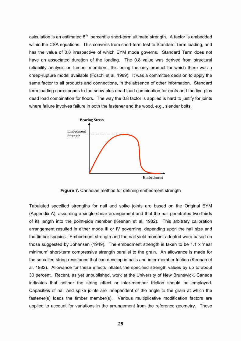
1989). The values represent the ultimate (peak) bearing capacity (Fig. 7). Thus, the
embedment values adopted in Canada do not have the same basis as those in the USA.
Embedment properties for wood members are related to the short-term ultimate strength of
the material. Empirical rules apply the yield load equations to timber-to-concrete
connections. Fastener yield moments are estimated from data in the literature (McLain and
Thangjitham 1983), and minimum permitted yield strength for the grade of bolt used. It is
assumed MY = yield stress x plastic section modulus (d3/6). The output from the EYM
25
calculation is an estimated 5th percentile short-term ultimate strength. A factor is embedded
within the CSA equations. This converts from short-term test to Standard Term loading, and
has the value of 0.8 irrespective of which EYM mode governs. Standard Term does not
have an associated duration of the loading. The 0.8 value was derived from structural
reliability analysis on lumber members, this being the only product for which there was a
creep-rupture model available (Foschi et al. 1989). It was a committee decision to apply the
same factor to all products and connections, in the absence of other information. Standard
term loading corresponds to the snow plus dead load combination for roofs and the live plus
dead load combination for floors. The way the 0.8 factor is applied is hard to justify for joints
where failure involves failure in both the fastener and the wood, e.g., slender bolts.
Figure 7. Canadian method for defining embedment strength
Tabulated specified strengths for nail and spike joints are based on the Original EYM
(Appendix A), assuming a single shear arrangement and that the nail penetrates two-thirds
of its length into the point-side member (Keenan et al. 1982). This arbitrary calibration
arrangement resulted in either mode III or IV governing, depending upon the nail size and
the timber species. Embedment strength and the nail yield moment adopted were based on
those suggested by Johansen (1949). The embedment strength is taken to be 1.1 x �near
minimum� short-term compressive strength parallel to the grain. An allowance is made for
the so-called string resistance that can develop in nails and inter-member friction (Keenan et
al. 1982). Allowance for these effects inflates the specified strength values by up to about
30 percent. Recent, as yet unpublished, work at the University of New Brunswick, Canada
indicates that neither the string effect or inter-member friction should be employed.
Capacities of nail and spike joints are independent of the angle to the grain at which the
fastener(s) loads the timber member(s). Various multiplicative modification factors are
applied to account for variations in the arrangement from the reference geometry. These
Embedment
Bearing Stress
Embedment Strength

26
account for factors such as the number of joint planes, �substandard� member thickness, nail
�clinching� and toe nailing. Without exception, these modification factors are based on
empirical evidence.
CSA capacities for dowel type fasteners make no allowance for the possibility that restraint
at the head of a nail, spike or bolt will enhance the capacity of a joint. For nails and spikes it
is presumed that the capacity of a joint is linearly proportional to the number of nails.
However for joints having a number of bolts, drift pins or coach screws capacities are
adjusted to account for uneven force distribution. Prior to the 1989 edition of CSA Standard
086.1 (CSA 1989), the approach for accounting for this was the same as in the NDS (AFPA
1997). Since then, empirical adjustments have been established to account for the number
of bolts in a row, the loaded end distance (distance between the last fastener and the end of
the member), and the number of rows of fasteners. Only the �number of rows� adjustment is
applied when bolts load the timber member(s) perpendicular to the grain. Essentially these
were an emergency measure, in response to data from two ad-hoc series of tensile tests on
steel-timber-steel bolted joints having one or more rows of bolts aligned parallel to the axis of
a glued-laminated-timber member (Masse et al. 1989; Yasumura et al. 1987). The CSA
�group effect� adjustments are rather constricting and preclude use of connections with a
large number of bolts (very little increase in capacity is available for more than about 20
bolts).
CSA Standard 086.1 requires that certain minimum requirements be met with regard to the
arrangement of fasteners in a joint, so as to reduce the possibility of premature brittle failure.
Adjustments must be made to specified strengths to account for the effects of non-reference
moisture and duration of loading conditions.
Supporting Standards and Documents
The following standards provide support and information needed to use the design
procedures. In Fig. 8, they are placed in the context of the diagram given in Fig. 1.
• CSA Standard 086-M84. Engineering design in wood. Canadian Standards Association,
Toronto, ON.
• CSA Standard 086.1-94. Engineering design in wood (limit states design). Canadian
Standards Association, Toronto, ON.
• Whale, L.R.J. and Smith, I. 1989. �A method for measuring the embedding
characteristics of wood and wood based materials�, Materials and Structures, 22, 403-
410.
27
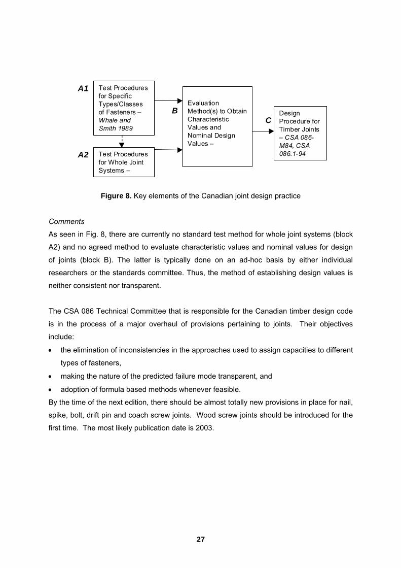
Figure 8. Key elements of the Canadian joint design practice
Comments
As seen in Fig. 8, there are currently no standard test method for whole joint systems (block
A2) and no agreed method to evaluate characteristic values and nominal values for design
of joints (block B). The latter is typically done on an ad-hoc basis by either individual
researchers or the standards committee. Thus, the method of establishing design values is
neither consistent nor transparent.
The CSA 086 Technical Committee that is responsible for the Canadian timber design code
is in the process of a major overhaul of provisions pertaining to joints. Their objectives
include:
• the elimination of inconsistencies in the approaches used to assign capacities to different
types of fasteners,
• making the nature of the predicted failure mode transparent, and
• adoption of formula based methods whenever feasible.
By the time of the next edition, there should be almost totally new provisions in place for nail,
spike, bolt, drift pin and coach screw joints. Wood screw joints should be introduced for the
first time. The most likely publication date is 2003.
DesignProcedure forTimber Joints� CSA 086-M84, CSA086.1-94
EvaluationMethod(s) to ObtainCharacteristicValues andNominal DesignValues �
Test Proceduresfor SpecificTypes/Classesof Fasteners �Whale andSmith 1989
Test Proceduresfor Whole JointSystems �
A1
A2
BC

28
European Code
Overview of Design Methods
The situation in Europe is somewhat complicated owing to the many national and
multinational technical/code writing bodies that are involved. The European Committee for
Standardisation (CEN) has published a model design code Structural Timber Design Code
with the designation Eurocode 5 (CEN 1995). This is a partial coefficient based LSD format.
There is a raft of supporting European test standards detailing how joints and joint
components are to be tested. Many of them are being �fast-tracked� to become ISO
standards. Various countries within Europe have developed/are developing National
Application Documents that meld Eurocode 5 (EC5) with local needs, tradition and design
practices. Although the documents are available it does not mean that they have yet
superseded prior codes. As discussed in respect of the US code, what is permitted within
political jurisdictions is controlled from within. It is understood that both WSD and LSD
methods are used over wide areas of Europe. Scandinavia was the first region to fully
embrace LSD. Because of the difficulty in saying what exactly is the situation, this document
takes a liberal approach in describing the state of the �design art�.
Technical Basis
The EC5 is written to a partial coefficient LSD format, and is intended to be consistent with
partial coefficient loading codes. Conceptually the form of the design equation for a member
or joint is:
Rd ≥ ∑ αFi Fi
where
Rd = Rk kmod / αm
and
Rd = design resistance
Rk = characteristic resistance
kmod = composite modification factor
αm = material resistance partial coefficient = φ-1
(inverse of the resistance factor φ that is used in non-European
countries)
∑ αFi Fi = summation of factored load effects, schematic
(αFi = partial load coefficient, Fi = load effect from wind, snow, etc)
29
The characteristic resistances Rk is a 5th percentile value determined from laboratory tests of
about 5 minute duration to failure, using wood materials conditioned at 20oC and 65%
relative humidity (about 12% moisture content for solid wood). Partial coefficients are
assigned values by the appropriate body within any country via the National Application
Document. Values are suggested in EC5 as a guide to national bodies. The composite
modification factor adjusts from reference to design conditions, e.g., to account for the
service environment and duration of the loading.
Rules are given covering the design of connections made with dowel type fasteners (nails,
bolts, screws, etc), and surface connections made with shear-plates, split-rings and toothed
plate connectors. As in other sections of this review, discussion is limited to design of dowel
type fastener joints.
Characteristic resistances for dowel type fastener joints are derived using the Original EYM
equations (Johansen 1949), Appendix A. The effects of tension in the dowel, inter-member
friction, and restraint at the ends (e.g., due to nail or bolt heads) are ignored. In these
respects, the approach is equivalent to assumptions accepted in the USA (AFPA 1997). The
embedment strengths of members, sH values, are based on the maximum bearing resistance
(Fig. 7). Embedment properties are a function of fastener diameter, wood density and angle
of loading relative to the grain (except for nails). Fastener yield moment is determined by
testing, or by calculation assuming MY = (σU + σY)d3/12 where σU and σY are the ultimate and
yield stresses in tension. (Note: the notation has been changed from the original so as to be
consistent with the rest of this document.) Values of sH and MY entering the EYM equations
are first adjusted to account for changes in properties from reference to design conditions,
and to include partial safety factors. Assuming use of timber for all members and a steel
dowel fastener, the approach is as follows:
sH,d = kmod sH,k / αm,wood
MY = MY,k / αm,steel
where
sH,d = design embedment strength
sH,k = characteristic embedment strength
αm,wood = material partial coefficient for wood (> 1.0, typical value 1.3)
MY = design moment resistance
MY,k = characteristic moment resistance
αm,steel = material partial coefficient for steel (> 1.0, typical value 1.1)

30
Thus, for mode I and II failures Rd / Rk = kmod / αm,wood, while for mode IV failures Rd / Rk =
[kmod / (αm,wood αm,steel)]1/2. The ratio Rd / Rk is intermediate for mode III failures. The details of
the approach are not the same as in non-European countries. However, there are
similarities to the approach taken in the USA, in that adjustments for non-reference
conditions depend upon the slenderness of the fastener. The product of the calculations is
the design resistance of a joint with one fastener. For bolt and dowel (drift pin) joints with
fasteners arranged in a row parallel to the force in a member, the capacity is discounted in
proportion to the number of fasteners if there are more than six:
Effective number of fasteners = nef = 6 + 2(n-6)/3
where n is the number of fasteners aligned in a row. This is a very liberal reduction rule
compared with those used elsewhere (USA, Canada). It is understood that the EC5 rule is
based on judgement rather than data. More sophisticated approaches to the group of
fasteners effect on the strength of a connection are permitted, provided that they are at least
as stringent. For nailed joints, nef = n.
In the case of joints with steel plate members (not thin sheet steel) the EYM equations are
simplified by setting the embedment strength for such a member(s) equal to infinity. This
results in mode I embedment failure in the wood member(s), or a mode III or IV failure [with
a hinge located on the joint plane(s)] governing. This is a non-conservative approach.
Composite modification factor kmod is arrived at in a manner unique to EC5. The factor
accounts simultaneously for duration of the loading and the moisture conditions in service. A
curtailed set of kmod values is shown in Table 1. It is understood that the values are based on
ad-hoc test data, experience and committee judgement.

31
Table 1. Values of composite modification factor kmod for solid and glued-laminated timber
and plywood in Eurocode 5
Load duration class Services class 1 (MC< 12%)
Services class 2 (12% < MC < 20%)
Services class 3 (MC unlimited)
Permanent
(>10 yrs.)
0.60 0.60 0.50
Long-term
(6 mo. to 10 yrs.)
0.70 0.70 0.55
Medium-term
(1 wk. to 6 mo.)
0.80 0.80 0.65
Short-term
(<1 wk.)
0.90 0.90 0.70
Instantaneous 1.10 1.10 0.90
Note: MC values refer to those moisture contents typical of solid wood in the service class.
Fairly extensive guidance is given on calculation of slip in joints, and as for strength, is a
function of both the service class and the duration of the loading. Rules are given regarding
aspects of connection design such as placement of fasteners to avoid premature brittle
failure. Nail spacing provisions are a function of the wood density, and whether or not there
is a predrilled lead hole.
The following papers provide fuller details: Ehlbeck and Larsen (1993), Whale and Smith
(1986a, 1986b, 1987), Whale et al. (1987), Ehlbeck and Werner (1992), and Blass et al.
(1995).
Supporting Standards
The following standards provide support and information needed to use the design
procedures. In Fig. 9, they are placed in the context of the diagram given in Fig. 1.
• Eurocode 5: Part 1.1 �Design of timber structures: General rules and rules for buildings�,
European Committee for Standardisation (CEN), Brussels, Belgium.
• EN 383. �Timber structures � Test methods � Determination of embedding strength and
foundation values for dowel type fasteners�, European Committee for Standardisation
(CEN), Brussels, Belgium.
• EN 409. �Timber structures � Test methods � Determination of the yield moment for
dowel type fasteners � Nails�, European Committee for Standardisation (CEN), Brussels,
Belgium.
32
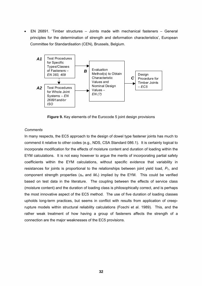
• EN 26891. �Timber structures � Joints made with mechanical fasteners � General
principles for the determination of strength and deformation characteristics�, European
Committee for Standardisation (CEN), Brussels, Belgium.
Figure 9. Key elements of the Eurocode 5 joint design provisions
Comments
In many respects, the EC5 approach to the design of dowel type fastener joints has much to
commend it relative to other codes (e.g., NDS, CSA Standard 086.1). It is certainly logical to
incorporate modification for the effects of moisture content and duration of loading within the
EYM calculations. It is not easy however to argue the merits of incorporating partial safety
coefficients within the EYM calculations, without specific evidence that variability in
resistances for joints is proportional to the relationships between joint yield load, PY, and
component strength properties (sH and MY) implied by the EYM. This could be verified
based on test data in the literature. The coupling between the effects of service class
(moisture content) and the duration of loading class is philosophically correct, and is perhaps
the most innovative aspect of the EC5 method. The use of five duration of loading classes
upholds long-term practices, but seems in conflict with results from application of creep-
rupture models within structural reliability calculations (Foschi et al. 1989). This, and the
rather weak treatment of how having a group of fasteners affects the strength of a
connection are the major weaknesses of the EC5 provisions.
DesignProcedure forTimber Joints� EC5
EvaluationMethod(s) to ObtainCharacteristicValues andNominal DesignValues �EN (?)
Test Proceduresfor SpecificTypes/Classesof Fasteners �EN 383, 409
Test Proceduresfor Whole JointSystems � EN26891and/orISO
A1
A2
BC

33
Summary of Issues
Based on the review of design practices and standards in Australia, USA, Canada and
Europe (based on Eurocode 5), we offer the following observations:
• Mechanics-based formulae allow designers to account for the many arrangement
specific parameters that affect the capacity and failure mode of a joint. They are
preferred over design equations that are based on empirical relationships alone because
of the continuing introduction and/or evolution of products, and the changes that occur in
the timber construction market.
• Methods for testing of whole joint systems that specify actual in-service joint
configuration and realistic in-service loads can be used to establish joint design
properties and/or evaluate the performance of a specific joint system. They are also
useful in evaluating design theories for joint systems (e.g., assessing EYM). The current
set of draft standards AS BBBB in Australia and New Zealand is one such method.
• There is a need for a rational and consistent method to establish characteristic values
and nominal values for design of joints. This is typically done, in most places, in a way
that is neither consistent nor transparent. Applicability of methods used in establishing
design values for timber/lumber should be investigated. The current Australian approach,
called the �Leicester method�, provides a simple way that seems to work well.
The European Yield Model (or its adaptations) provides a set of mechanics-based equations
for the design of joints with dowel-type fasteners that allows consideration of failure modes in
design and the flexibility of being applicable for joints with non-traditional members (e.g.,
new species or new composite). Having said this, we note that the use of EYM in design
codes and standards is not universally harmonious as generally believed. Many issues still
need careful consideration. These include the following:
• EYM equations still need empirical adjustments and simplifications that best suit local
conditions and/or practice;
• EYM predictions depend on the type of test used in deriving input properties; seemingly
small procedural differences in test methods and data interpretation techniques are
important;
• Tests on single nail joints are not very realistic in performance and with respect to
variability in joint strength;
• Applicability to large diameter bolts and other types of dowel-type fasteners (other than
nails and slender bolts) require further empirical adjustments;
34
• Effects of modification factors (e.g., moisture, duration of load, etc.) are not well
established; traditional modification factors specified in existing codes are used by
default;
• A species (or possibly density) related rules for minimum member thickness to avoid
premature splitting failures is necessary;
• A method to calculate variance in joint strength from variance in nail and wood properties
is needed; and
• Reliability-based calibration of resistance factors is needed.

35
Recommendations
General
Our primary recommendation is to fully develop the use of the European Yield Model (EYM)
for the design of dowel-type fasteners in Australia. As a first step, we should consider nails,
and, possibly, slender bolts. This process will involve developing:
1. an experimental program to establish properties and try the EYM concept to a range of
variables common in Australian condition; and
2. the infrastructure required to support the use of this design procedure.
The latter includes guidelines and/or standards to determine the input properties needed in
EYM-based design. Despite the amount of development and data available from other
countries, a fair amount of work still needs to be done to evaluate its applicability to a wide
range of Australian joints with dowel-type fasteners, and to introduce simplifications to make
the proposed design procedures easier to use.
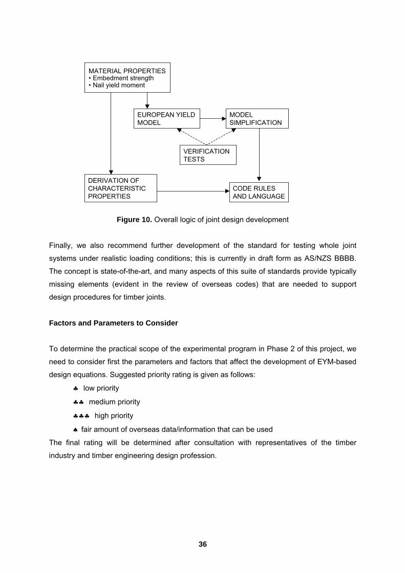
Figure 10 shows the overall logic of joint design development. The experimental program
involves evaluation of material properties to determine input values for the EYM equations
and of complete joint systems to validate the use of EYM theory and to provide data for
simplification of the equations. With acceptable methods of deriving characteristic values,
then new code rules can be developed and put into appropriate language.
In developing LSD procedures for timber joints, it is ideal to determine the appropriate
resistance factors, develop a method to estimate joint variability based only on data from
fastener and timber components of the joint, and conduct reliability analysis to calibrate the
method to accepted levels of performance.
36
Figure 10. Overall logic of joint design development
Finally, we also recommend further development of the standard for testing whole joint
systems under realistic loading conditions; this is currently in draft form as AS/NZS BBBB.
The concept is state-of-the-art, and many aspects of this suite of standards provide typically
missing elements (evident in the review of overseas codes) that are needed to support
design procedures for timber joints.
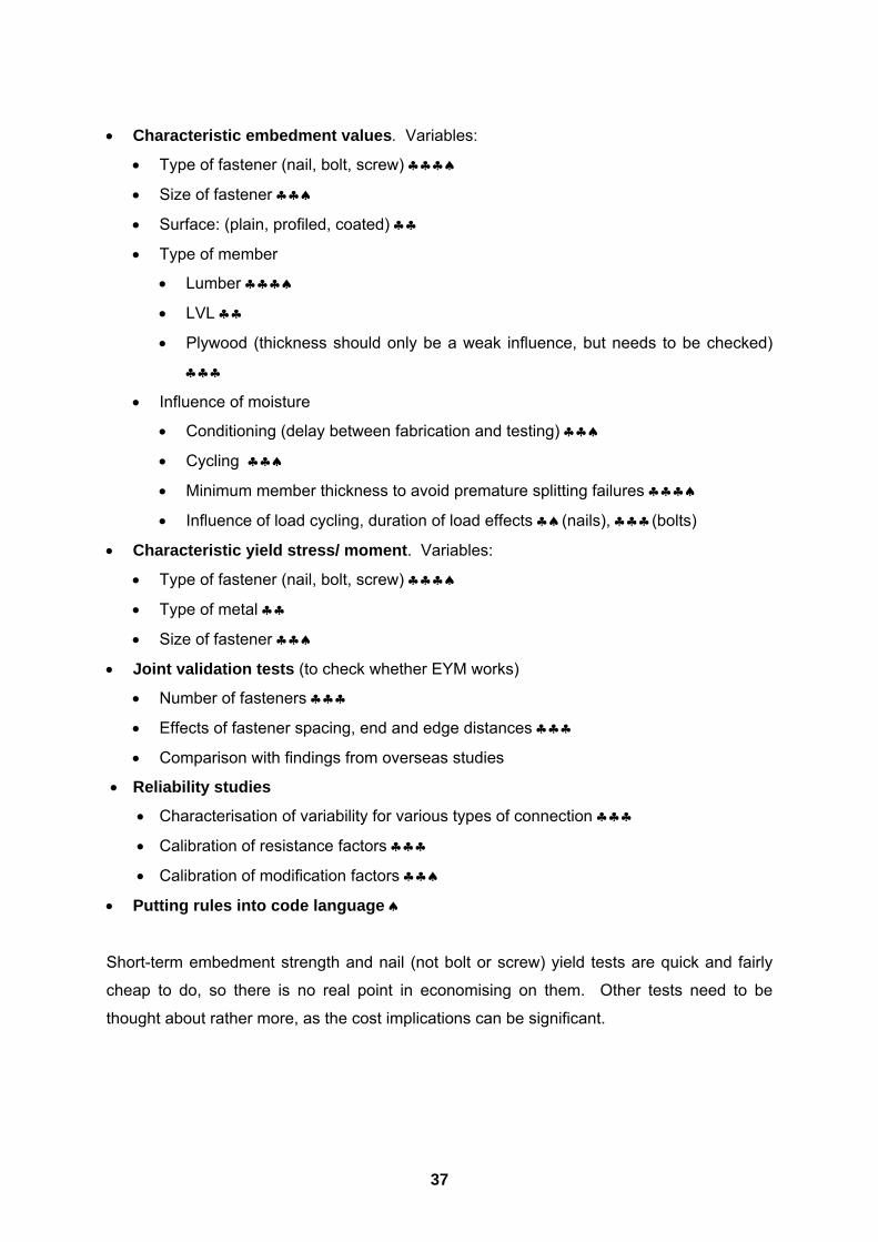
Factors and Parameters to Consider
To determine the practical scope of the experimental program in Phase 2 of this project, we
need to consider first the parameters and factors that affect the development of EYM-based
design equations. Suggested priority rating is given as follows:
♣ low priority
♣♣ medium priority
♣♣♣ high priority
♠ fair amount of overseas data/information that can be used
The final rating will be determined after consultation with representatives of the timber
industry and timber engineering design profession.
DERIVATION OFCHARACTERISTICPROPERTIES
MATERIAL PROPERTIES� Embedment strength� Nail yield moment
EUROPEAN YIELDMODEL
MODELSIMPLIFICATION
VERIFICATIONTESTS
CODE RULESAND LANGUAGE
37
• Characteristic embedment values. Variables:
• Type of fastener (nail, bolt, screw) ♣♣♣♠
• Size of fastener ♣♣♠
• Surface: (plain, profiled, coated) ♣♣
• Type of member
• Lumber ♣♣♣♠
• LVL ♣♣
• Plywood (thickness should only be a weak influence, but needs to be checked)
♣♣♣
• Influence of moisture
• Conditioning (delay between fabrication and testing) ♣♣♠
• Cycling ♣♣♠
• Minimum member thickness to avoid premature splitting failures ♣♣♣♠
• Influence of load cycling, duration of load effects ♣♠(nails), ♣♣♣(bolts)
• Characteristic yield stress/ moment. Variables:
• Type of fastener (nail, bolt, screw) ♣♣♣♠
• Type of metal ♣♣
• Size of fastener ♣♣♠
• Joint validation tests (to check whether EYM works)
• Number of fasteners ♣♣♣
• Effects of fastener spacing, end and edge distances ♣♣♣
• Comparison with findings from overseas studies
• Reliability studies
• Characterisation of variability for various types of connection ♣♣♣
• Calibration of resistance factors ♣♣♣
• Calibration of modification factors ♣♣♠
• Putting rules into code language ♠
Short-term embedment strength and nail (not bolt or screw) yield tests are quick and fairly
cheap to do, so there is no real point in economising on them. Other tests need to be
thought about rather more, as the cost implications can be significant.
38
References
1. AFPA 1991, �National design specification for wood construction�, NDS-1991, American Forest & Paper Association, Washington, DC.
2. AFPA 1997, �National design specification for wood construction�, NDS-1997, American Forest & Paper Association, Washington, DC.
3. AFPA 1999, �General dowel equations for calculating lateral connection values�, American Forest and Paper Association, Washington, DC, USA.
4. ASCE 1996a, Standard for Load and Resistance Factor Design for Engineered Wood Construction, ASCE 16-95, American Society of Civil Engineers, New York, NY.
5. ASCE 1996b, Mechanical Connections in Wood Structures, ASCE Manuals and Reports on Engineering Practice No. 84, American Society of Civil Engineers, New York, NY.
6. ASTM 1995a, �Determining the mechanical properties of externally threaded fasteners, washers, and rivets�, ASTM F606-95b, Volume 15.08 Fasteners, ASTM, West Conshohocken, PA.
7. ASTM 1995b, �Standard test method for determining yield moment of nails�, ASTM F1575-95, Volume 15.08 Fasteners, ASTM, West Conshohocken, PA.
8. ASTM 1996, �Establishing Allowable Properties for Visually-Graded Dimension Lumber from In-Grade Tests of Full-Size Specimens�, ASTM D1990-91. ASTM, West Conshohocken, PA.
9. ASTM 1997a, �Standard test method for evaluating dowel-bearing strength of wood and wood-based products�, ASTM D 5764-1997, Volume 4.10 Wood, ASTM, West Conshohocken, PA.
10. ASTM 1997b, �Standard test methods for mechanical fasteners in wood�, ASTM D1761-1997, Volume 4.10 Wood, ASTM, West Conshohocken, PA.
11. Blass, H.J., Aune, P., Choo, B.S., Goerlacher, R., Griffiths, D.R., Hilson, B.O., Racher, P. and Steck, G. 1995. Timber Engineering Step 1 (Section C � Joints). Centrum Hout, The Netherlands.
12. Blass, H.J., Ehlbeck, J. and Rouger, F. 1999, �Simplified design of joints with dowel-type fasteners�, Proceedings of Pacific Timber Engineering Conference (PTEC�99), Forest Research Bulletin 212, New Zealand Forest Research Institute Ltd., Rotorua, New Zealand, Vol. 3: 275-279.
13. Boughton, G.N. and Crews, K.I. 1998, Timber Design Handbook � In accordance with the Australian Limit State Timber Design Code AS1720.1-1997, SAA HB108�1998, Standards Australia, The Crescent, Homebush, NSW.
14. Bryant, A.H. and Hunt, R.D. 1999, �Estimates of joint strength from experimental tests�, Proceedings of Pacific Timber Engineering Conference (PTEC�99), Forest Research Bulletin 212, New Zealand Forest Research Institute Ltd., Rotorua, New Zealand, Vol. 2: 225-230.

39
15. CEN 1995a, Eurocode 5: Part 1.1 �Design of timber structures: General rules and rules for buildings�, European Committee for Standardisation (CEN), Brussels, Belgium.
16. CEN 1995b, EN 383. �Timber structures � Test methods � Determination of embedding strength and foundation values for dowel type fasteners�, European Committee for Standardisation (CEN), Brussels, Belgium.
17. CEN 1995c, EN 409. �Timber structures � Test methods � Determination of the yield moment for dowel type fasteners � Nails�, European Committee for Standardisation (CEN), Brussels, Belgium.
18. CEN 1995d, EN 26891. �Timber structures � Joints made with mechanical fasteners � General principles for the determination of strength and deformation characteristics�, European Committee for Standardisation (CEN), Brussels, Belgium.
19. Cramer, C.O. 1968, �Load distribution in multiple-bolt tension joints�, ASCE Journal of Structural Engineering, 94(5), 1101-1117.
20. CSA 1984, �Engineering design in wood�, CSA Standard 086-M84, Canadian Standards Association, Toronto, ON.
21. CSA 1989, �Engineering design in wood�, CSA Standard CSA Standard 086.1-89, Canadian Standards Association, Toronto, ON.
22. CSA 1994, �Engineering design in wood (limit states design)�, CSA Standard 086.1-94, Canadian Standards Association, Toronto, ON.
23. DeGrace, R.F. 1986, �Commentary on CSA Standard 086.1-M84 Engineering design in wood (limit states design)�, Special Publication 086.1.1-M1986, Canadian Standards Association, Toronto, ON.
24. Department of Works and Housing 1946, �A report on the structural soundness of unseasoned timbers used in structures erected for war purposes�, Department of Works and Housing, Melbourne, Australia.
25. Dolan, J.D., Gutshall, S.T. and McLain, T.E. 1995, �Monotonic and cyclic tests to determine short-term load duration performance of nail and bolt connections, Vol. 1: Summary report�, Report No. TE-1994-001, Timber Engineering Center, Virginia Polytechnic Institute and State University, Blacksburg, Virginia.
26. Dolan, J.D., Gutshall, S.T. and McLain, T.E. 1996, �Determination of short-term duration-of-load performance of nailed and bolted connections using sequential phased displacement tests, Vol. 1: Summary report�, Report No. TE-1994-003, Timber Engineering Center, Virginia Polytechnic Institute and State University, Blacksburg, Virginia.
27. Ehlbeck, J. and Larsen, H.J. 1993, �Eurocode 5 � Design of timber structures: joints�, Proceedings of 1992 International Workshop on Wood Connectors, Forest Products Society, Madison , WI, USA, 9-23.
28. Ehlbeck, J. and Werner, H. 1992, �Softwood and hardwood embedment strength for dowel type fasteners�, Proceedings International Council for Building Research Studies and Documentation: Working Commission W18 - Timber Structures, Ahus, Sweden.

40
29. Ehlbeck, J., Siebert, W. and Werner H. 1990, �Nail and nail wire bending tests�, Department of Timber Engineering, University Fridericiana Karlsruhe, Germany, 11pp.
30. Foliente, G.C. 1998, �Design of timber structures subjected to extreme loads�, Progress in Structural Engineering and Materials 1(3): 236-244.
31. Foliente, G.C. and Leicester, R.H. 1996, �Evaluation of mechanical joint systems in timber structures�, Proceedings of the 25th Forest Products Research Conference, CSIRO Division of Forestry and Forest Products, Clayton, Victoria, Australia, Vol. 1, Paper 2/16, 8 pp.
32. Foliente, G.C., Seath, C.A. and Peters, D.J. 1996, �Mechanical testing and evaluation of statically loaded timber joints�, DBCE Doc 96/124 (M), CSIRO Building, Construction and Engineering, Highett, Victoria.
33. Foliente, G.C., Karacabeyli, E. and Yasumura, M. 1998, �International test standards for joints in timber structures under earthquake and wind loads�, Paper T-222-6 in Proceedings of the Structural Engineers World Congress (SEWC �98) (CD-Rom), San Francisco, California, USA.
34. Foschi, R.O., Folz, B.R. and Yao, F.Z. 1989, �Reliability-based design of wood structures�, Structural Research Series, Report No. 34, Department of Civil Engineering, University of British Columbia, Vancouver, BC.
35. ICBO 1997, Uniform Building Code, International Conference of Building Officials, Whittier, California.
36. Johansen, K W. 1949, �Theory of timber connectors�, Publication No. 9. International Association of Bridges and Structural Engineering, Bern, Switzerland, 249-262.
37. Keenan, F.J., Lepper, M.M. and Marshall, C.M. 1982, �Improved design of fastenings in timber structures based on limit states design procedures�. Contract Report to Canadian Forestry Service, Hull, QB.
38. Langlands, I. and Thomas, A.J. 1939, Handbook of structural timber design, Government Printer, Melbourne, Australia.
39. Lantos, G. 1967, �Load distribution in multiple mechanical fasteners in joints subjected to direct load�, research Report E/RR/28, Timber Research and Development Association, Hughenden valley, UK.
40. Larsen, H.J. 1979, �Design of bolted joints�, Proceedings International Council for Building Research Studies and Documentation: Working Commission W18 - Timber Structures, Bordeaux, France.
41. Leicester, R.H. 1986, �Confidence in estimates of characteristic values�, Proceedings of 19th Meeting of CIB W18, Firenze, Italy.
42. Leicester, R.H. 1993, �Connector code development: an Australian overview�, Proceedings of 1992 International Workshop on Wood Connectors, Forest Products Society, Madison , WI, USA, 31-37.
41
43. Lepper, M. and Smith, I. 1995, �Fastenings (commentary on chapter 10 of CSA Standard 086.1-1994)�, In Wood Design Manual 1995, Canadian Wood Council, Ottawa, ON, 647-666.
44. Lhuede, E.P. 1986, �Research on timber connectors in CSIRO�, Procs. 22nd Forest Products Research Conference, Vol.1, CSIRO Division of Chemical and Wood Technology, Clayton, Australia.
45. Lhuede, E.P. 1988, �Connector systems�, Timber Structures Seminar, Standards, Australia, The Crescent, Homebush, NSW.
46. Lhuede, E.P. 1990, �A review of bolted timber connections�, Paper 2/2, Procs. 23rd Forest Products Research Conference, Vol. 1, CSIRO Division of Forestry and Forest Products, Clayton, Australia.
47. Mack, J.J. 1960, �The strength of nailed timber joints, I�, Technological Paper No. 9, CSIRO Division of Forest Products, Melbourne, Australia.
48. Mack, J.J. 1962, �The strength of nailed timber joints, II�, Technological Paper No. 21, CSIRO Division of Forest Products, Melbourne, Australia.
49. Mack, J.J. 1966, �The strength and stiffness of nailed joints under short duration loading�, Technological Paper No. 40, CSIRO Division of Building Research, Melbourne, Australia.
50. Mack, J.J. 1978, �The grouping of species for the design of timber joints with particular application to nailed joints�, Technical Paper, Second Series No. 26, CSIRO Division of Building Research, Highett, Australia
51. Mack, J.J. 1979, �Research on timber fasteners�, Topic 2/4, Procs. 19th Forest Products Research Conference, Supplement, CSIRO Division of Building Research, Highett, Australia.
52. Madsen, B. 1992. Structural Behaviour of Timber. Timber Engineering Ltd., North Vancouver, BC.
53. Madsen, B. 1998, �Reliable timber connections�, Progress in Structural Engineering and Materials, 1(3), 245-252.
54. Masse, D.I., Salinas, J.J. and Turnbull, J. 1989, �Lateral strength and stiffness of single and multiple bolts in glued-laminated timber loaded parallel to grain�, Contribution No. C-029, Engineering and Statistical Research Centre, Research Branch, Agriculture Canada, Ottawa, Canada.
55. McLain, T.E. 1984, �Mechanical fastening of structural wood members � design and research status�, Proceedings of Workshop on Structural Wood Research, American Society of Civil Engineers, New York, NY: 31-70.
56. McLain, T.E. 1993, �Connector code development and application in the United States: generic fasteners�, In Proceedings 1992 International Workshop on Wood Connectors, Forest Products Society, Madison, WI, 52-56.
57. McLain, T.E. and Thangjitham, S. 1983, �Bolted wood joint yield model�, Journal of the Structural Division, ASCE 109(8): 1820-1835.
42
58. Mohammad, M.A.H., Quenneville, P. and Smith, I. 1997, “Bolted timber connections: Investigation on failure mechanism�, Proceedings International Union of Forestry Research Organizations (IUFRO) S5.02: Timber Engineering Group, Copenhagen, 309-323.
59. Nordtest 1981, �Nails in wood, embedding strength, NT Build 135�, Nordtest, Stockholm, Sweden.
60. Pearson, R.G. 1965, �The establishment of working stresses for groups of species�, Technological Paper No. 35, CSIRO Division of Forest Products, Melbourne, Australia.
61. Pearson, R.G., Kloot, N.H. and Boyd, J.D. 1958, Timber Engineering Design Handbook, Jacaranda Press, Melbourne, Australia.
62. SAA 1998, AS 1649� 1998. Timber � Methods of test for mechanical fasteners and connectors � Basic working loads and characteristic strengths. Standards Australia, The Crescent, Homebush, NSW.
63. SAA 1999, AS 1684� 1999. Residential timber-framed construction. Part 1 Design Criteria; Part 2 Non-cyclonic area; Part 3 Cyclonic areas; Part 4 Simplified � Non-cyclonic areas. Standards Australia, The Crescent, Homebush, NSW.
64. SAA 1988, AS 1720.1� 1988. Timber Structures, Part 1: Design methods. Standards Australia, The Crescent, Homebush, NSW.
65. SAA 1997, AS 1720.1� 1997. Timber Structures, Part 1: Design methods. Standards Australia, The Crescent, Homebush, NSW.
66. SAA 1992, AS/NZS 4063 Timber�Stress-graded�In-grade Strength and Stiffness Evaluation. Standards Australia, The Crescent, Homebush, NSW.
67. SAA 1998, AS/NZS BBBB (Committee Draft). Timber � Methods for evaluation of mechanical joint systems, Part 1: Static loading; Part 2: Cyclonic wind loading; Part 3: Earthquake loading. Standards Australia, The Crescent, Homebush, NSW.
68. Smith, I. 1998. �Joints in timber structures: State-of-the-art knowledge in North America�, Keynote address, session 4, Procs. International Conf. Control of the Semi-rigid Behaviour of Civil Engineering Structural Connections, Liege, 17-19 Sept 1998, European Commission, Luxembourg, pp. 255-264.
69. Smith, I., Whale, L.R.J., Anderson, C., Hilson, B.O. and Rodd, P.D. 1988, �Design properties of laterally loaded nailed or bolted joints�, Canadian Journal of Civil Engineering, 15(4), 633-643.
70. Stringer, G.R. 1991, �The application of Johansen�s yield theory to Australian nailed timber joints�, CEB491 Project, School of Civil Engineering, Queensland University of Technology, Brisbane, Queensland, 122 pp.
71. Stringer, G.R. 1993, �The application of Johansen�s yield theory to Australian nailed timber joints�, Proceedings 24th Forest Products Research Conference, CSIRO Forest Products Division, Clayton, Victoria, Australia, vol. 1, 6/8, 14pp.
72. Tan, D. and Smith, I. 1999, �Failure in-the-row model for bolted timber connections�, ASCE Journal of Structural Engineering, 125(7), 713-718.

43
73. Trayer, G.W. 1932, �The bearing strength of wood under bolts�, Technical Bulletin No. 332, US Department of Agriculture, Washington, DC.
74. Tucker, B.J., Pollock, D.G., Fridley, K.J. and Peters, J.J. 2000, �Governing yield modes for common bolted and nailed wood connections�, Practice Periodical on Structural Design and Construction ASCE 5(1): 14-26.
75. USDA 1987, Wood Handbook: Wood as an Engineering Material, Agriculture Handbook 72, United States Department of Agriculture, Washington, DC, (Chapter 7 - Fastenings).
76. Whale, L.R.J. and Smith, I. 1986a, �Mechanical joints in structural timberwork - Information for probabilistic design�, Research Report 17/86, Timber Research and Development Association, Hughenden Valley, UK.
77. Whale, L.R.J. and Smith, I. 1986b, �Design of nailed and bolted joints - Proposals for the revision of existing formulae in draft Eurocode 5 and the CIB Code�. Proceedings International Council for Building Research Studies and Documentation: Working Commission W18 - Timber Structures, Florence, Italy.
78. Whale, L.R.J. and Smith, I. 1987, �Mechanical timber joints�, Research Report 18/86, Timber Research and Development Association, Hughenden Valley, UK.
79. Whale, L.R.J. and Smith, I. 1989, �A method for measuring the embedding characteristics of wood and wood based materials�, Materials and Structures, 22, 403-410.
80. Whale, L.R.J., Smith, I. and Larsen, H.J. 1987, �Design of nailed and bolted joints - Proposals for the revision of existing formulae in draft Eurocode 5 and the CIB Code�, Proceedings International Council for Building Research Studies and Documentation: Working Commission W18 - Timber Structures, Dublin, Ireland.
81. Wood, L.W. 1951, �Relation of strength of wood to duration of load�, Report No. R1916, US Forest Products Laboratory, Madison, Wisconsin.
82. Zahn, J.J. 1991, �Design equation for multiple-fastener wood connections�, ASCE Journal of Structural Engineering, 117(11), 3477-3486.
83. Yasumura, M., Murota, T. and Sakai, H. 1987, �Ultimate properties of bolted joints in glued-laminated timber�, Paper 20-7-3, Proceedings International Council for Building Research Studies and Documentation: Working Commission W18A - Timber Structures.
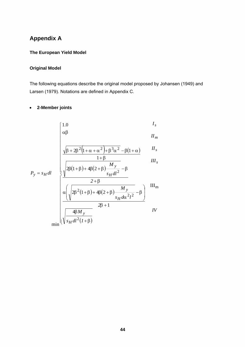
44
Appendix A
The European Yield Model
Original Model
The following equations describe the original model proposed by Johansen (1949) and
Larsen (1979). Notations are defined in Appendix C.
• 2-Member joints
( ) ( )
( ) ( )
( ) ( )
( )
IV
III
II
II
I
1dls
M2
lds
M2
dls
M
dlsP
s
s
m
s
H
y
H
y
H
y
Hy
m
2
222
2
2322
III
41
2412
2412
1112
1.0
min
β+
β+β
β−
αβ+β+β+βα
β+
β−β+β+β+β
β+α+β−αβ+α+α+β+β
αβ
=
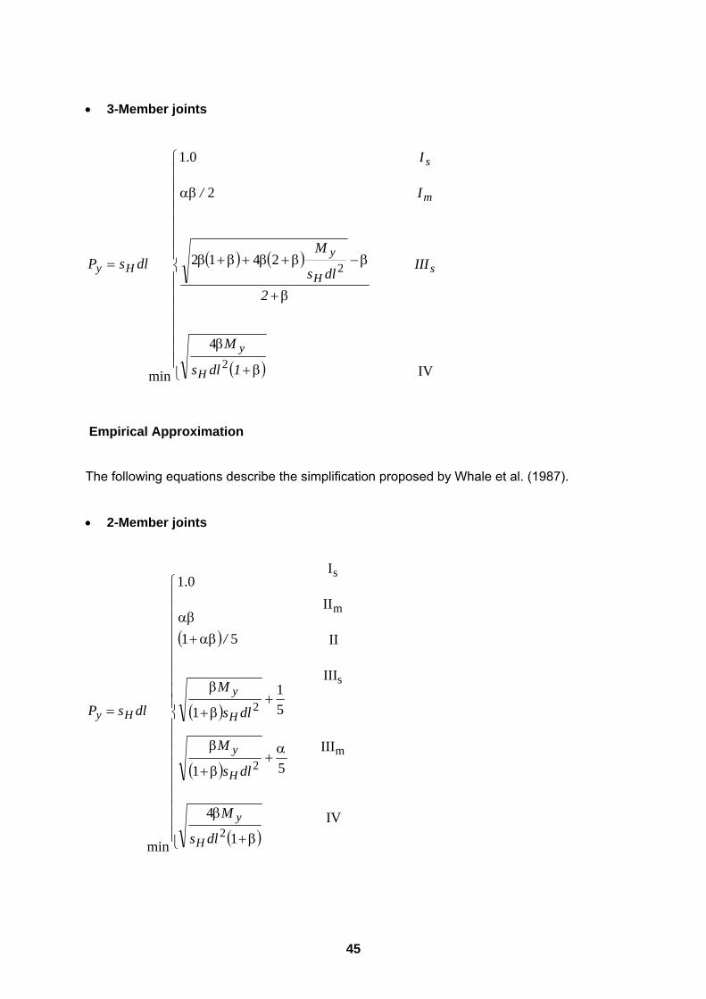
45
• 3-Member joints
( ) ( )
( ) IV
4
2412
2
1.0
min2
2 s
m
s
H
y
H
yHy III
I
I
1dls
M
2dls
M
/
dlsP
β+
β
β+
β−β+β+β+β
αβ
=
Empirical Approximation
The following equations describe the simplification proposed by Whale et al. (1987).
• 2-Member joints
( )
( )
( )
( )IV
III
III
II
II
I
1
4
51
51
1
51
1.0
min
m
s
m
s
2
2
2
β+
β
α+
β+
β
+β+
β
αβ+αβ
=
dls
M
dls
M
dls
M
/
dlsP
H
y
H
y
H
y
Hy
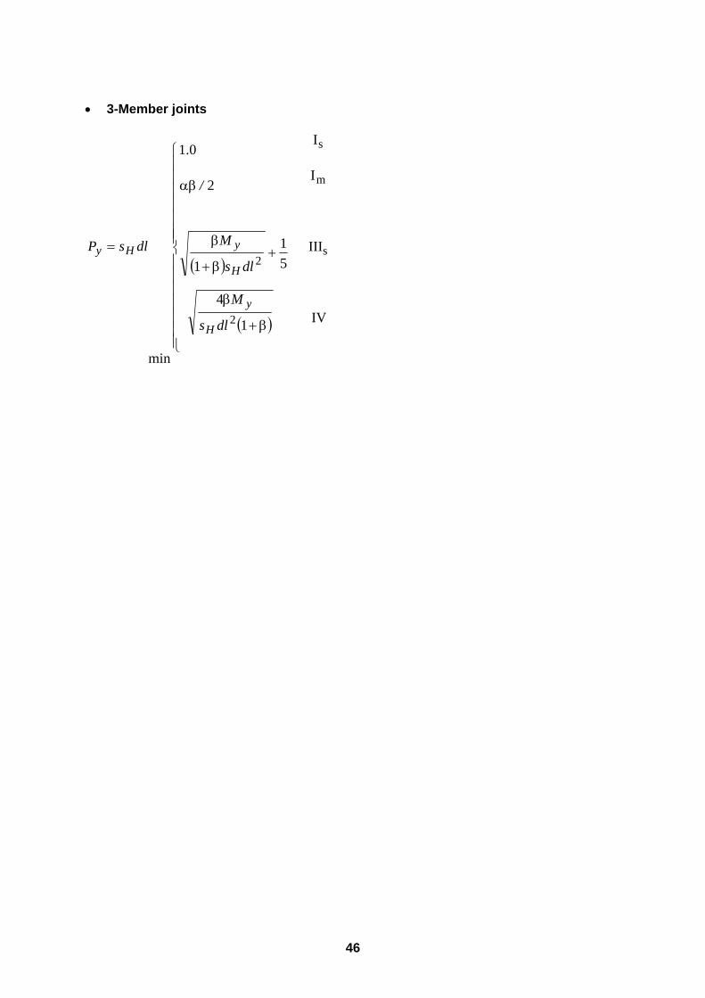
46
• 3-Member joints
( )
( ) IV
III
I
I
1
4
51
1
2
1.0
min
s
m
s
2
2
β+
β
+β+
β
αβ
=
dls
M
dls
M
/
dlsP
H
y
H
yHy
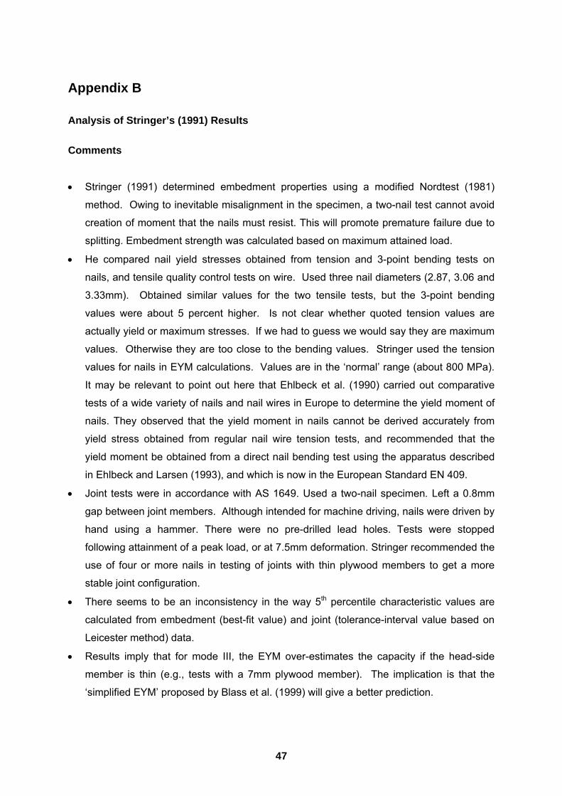
47
Appendix B
Analysis of Stringer’s (1991) Results Comments
• Stringer (1991) determined embedment properties using a modified Nordtest (1981)
method. Owing to inevitable misalignment in the specimen, a two-nail test cannot avoid
creation of moment that the nails must resist. This will promote premature failure due to
splitting. Embedment strength was calculated based on maximum attained load.
• He compared nail yield stresses obtained from tension and 3-point bending tests on
nails, and tensile quality control tests on wire. Used three nail diameters (2.87, 3.06 and
3.33mm). Obtained similar values for the two tensile tests, but the 3-point bending
values were about 5 percent higher. Is not clear whether quoted tension values are
actually yield or maximum stresses. If we had to guess we would say they are maximum
values. Otherwise they are too close to the bending values. Stringer used the tension
values for nails in EYM calculations. Values are in the �normal� range (about 800 MPa).
It may be relevant to point out here that Ehlbeck et al. (1990) carried out comparative
tests of a wide variety of nails and nail wires in Europe to determine the yield moment of
nails. They observed that the yield moment in nails cannot be derived accurately from
yield stress obtained from regular nail wire tension tests, and recommended that the
yield moment be obtained from a direct nail bending test using the apparatus described
in Ehlbeck and Larsen (1993), and which is now in the European Standard EN 409.
• Joint tests were in accordance with AS 1649. Used a two-nail specimen. Left a 0.8mm
gap between joint members. Although intended for machine driving, nails were driven by
hand using a hammer. There were no pre-drilled lead holes. Tests were stopped
following attainment of a peak load, or at 7.5mm deformation. Stringer recommended the
use of four or more nails in testing of joints with thin plywood members to get a more
stable joint configuration.
• There seems to be an inconsistency in the way 5th percentile characteristic values are
calculated from embedment (best-fit value) and joint (tolerance-interval value based on
Leicester method) data.
• Results imply that for mode III, the EYM over-estimates the capacity if the head-side
member is thin (e.g., tests with a 7mm plywood member). The implication is that the
�simplified EYM� proposed by Blass et al. (1999) will give a better prediction.
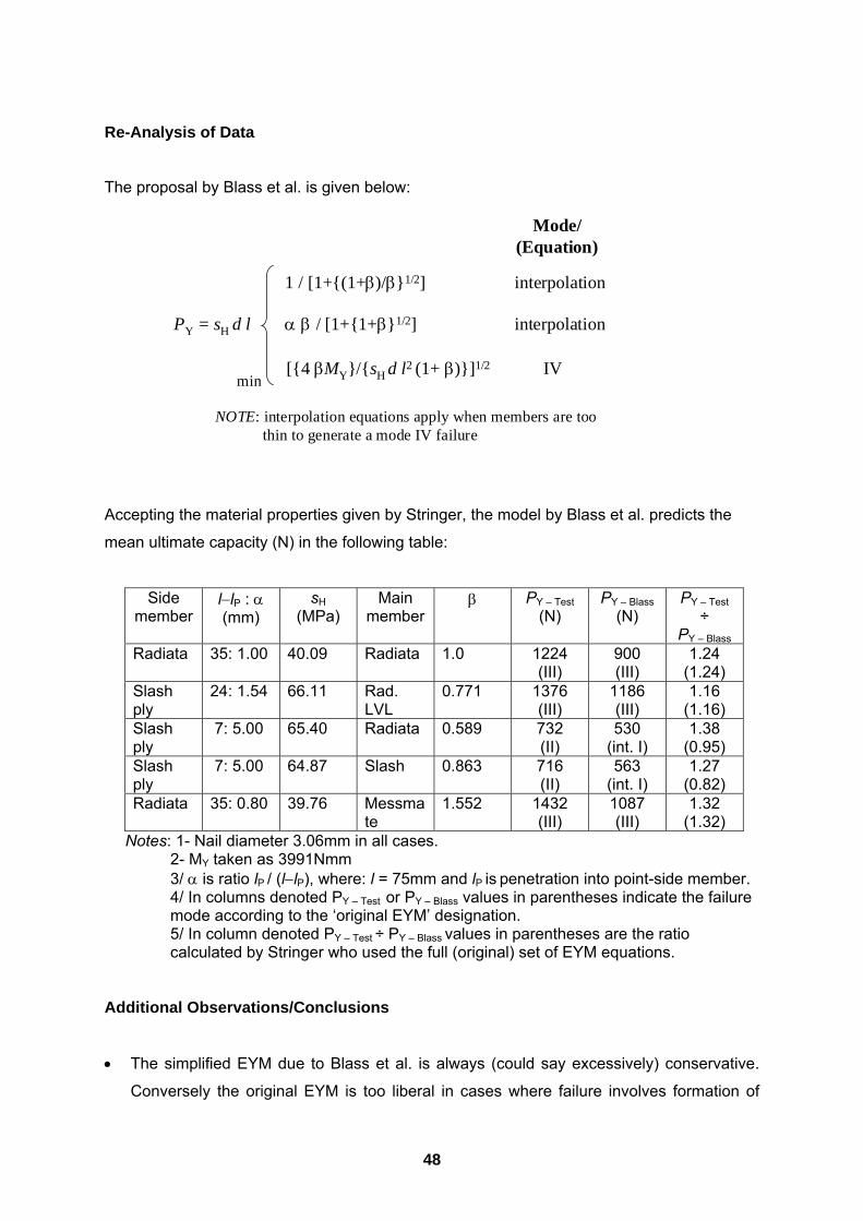
48
Re-Analysis of Data
The proposal by Blass et al. is given below:
Accepting the material properties given by Stringer, the model by Blass et al. predicts the
mean ultimate capacity (N) in the following table:
Side member
l−lP : α (mm)
sH (MPa)
Main member
β PY � Test (N)
PY � Blass (N)
PY � Test ÷
PY � Blass Radiata 35: 1.00 40.09 Radiata 1.0 1224
(III) 900 (III)
1.24 (1.24)
Slash ply
24: 1.54 66.11 Rad. LVL
0.771 1376 (III)
1186 (III)
1.16 (1.16)
Slash ply
7: 5.00 65.40 Radiata 0.589 732 (II)
530 (int. I)
1.38 (0.95)
Slash ply
7: 5.00 64.87 Slash 0.863 716 (II)
563 (int. I)
1.27 (0.82)
Radiata 35: 0.80 39.76 Messmate
1.552 1432 (III)
1087 (III)
1.32 (1.32)
Notes: 1- Nail diameter 3.06mm in all cases. 2- MY taken as 3991Nmm 3/ α is ratio lP / (l−lP), where: l = 75mm and lP is penetration into point-side member. 4/ In columns denoted PY � Test or PY � Blass values in parentheses indicate the failure mode according to the �original EYM� designation. 5/ In column denoted PY � Test ÷ PY � Blass values in parentheses are the ratio calculated by Stringer who used the full (original) set of EYM equations.
Additional Observations/Conclusions
• The simplified EYM due to Blass et al. is always (could say excessively) conservative.
Conversely the original EYM is too liberal in cases where failure involves formation of
PY = sH d l
min
Mode/(Equation)
1 / [1+{(1+β)/β}1/2] interpolation
[{4 βMY}/{sH d l2 (1+ β)}]1/2 IV
α β / [1+{1+β}1/2] interpolation
NOTE: interpolation equations apply when members are too thin to generate a mode IV failure
49
only one plastic hinge, which for the joint arrangements studied was located in the point-
side member.
• It is controversial/debatable how to estimate strength of a joint from a test record
exhibiting a very ductile response, which is usually the case for joints with laterally
loaded nails. Bearing this in mind, ratios of test to predicted strength quoted by any
author are subjective.

50
Appendix C
Notations The following notations are used in this report:
α = ratio of thickness of main/centre member to thickness of side member
αm = material resistance partial coefficient = φ-1
αFi = partial load coefficient
∑αFi Fi = factored design action effect
β = ratio of embedment strength of main member to embedment strength of side
member
� = capacity factor (known as a resistance factor in North America)
(�Nj) = �k1 � kj n Qk = factored resistance
d = diameter of fastener
EYM = European Yield Model
Fi = load effect from wind, snow, etc
ki = modification factor accounting for departures from reference conditions for Qk
kmod = composite modification factor
l = thickness of side member(s)
= thickness of head-side member in a single-shear nailed joint
lP = penetration into point-side member
LRFD = Load and Resistance Factor Design
LSD = Limit States Design
MY = yield moment of fastener
n = number of fasteners
nef = effective number of fasteners
N* = factored design action effect
PY = yield load per fastener per joint plane
Qk = characteristic capacity of a fastener
Rd = Rk kmod / αm = factored resistance
Rk = characteristic resistance
sH = embedment strength of side member(s)
WSD = Working Stress Design


![January 2017 Version 2.1 Coop Negative List for Textile ... und... · January 2017 Version 2.1 Limit Test Method Limit [µg/L] Test Method Limit [mg/kg] Test Method Input Chemicals](https://img.pdfslide.us/doc/110x75/5c86cdca09d3f2815e8cbbf6/january-2017-version-21-coop-negative-list-for-textile-und-january-2017.jpg)