Embed Size (px)
Citation preview
NASA Contractor Report 3517
Development of an Advanced Composite Aileron for the L-101 1 Transport Aircraft
C. F. Griffin and E. G. Dunning
CONTRACT NASl-1506y FEBRUARY 1982
TECH LIBRARY KAFB, NM
I 1#111 Ill11 lllll Ill11 lllll Ill1 lllll HI II 0062222
FEDD DOCUMENT
Note that this document bears the label "FEDD," an acronym for "FOR EARLY DOMESTIC DISSEMINATION.’ The FEDD label is affixed to documents that may contain information having high commercial potential.
The FEDD concept was developed as a result of the desire to maintain U.S. leadership in world trade markets and encourage a favorable balance of trade. Since the availability of tax- supported U.S. technology to foreign business interests could represent an unearned benefit, research results that may have high commercial potential are being distributed to U.S. industry in advance of general release.
The recipient of this report must treat the information it contains according to the conditions of the FEDD label on the front cover.
I

-- -y
NASA Contractor Report 3517
Development of an Advanced Composite Aileron for the L-101 1 Transport Aircraft
C. F. Griffin Lockheed Corporation Burbank, California
E. G. Dunning Avco Corporation Nasbde, Tennessee
Prepared for Langley Research Center under Contract NAS l-15069
National Aeronautics and Space Administration
Scientific and Technical Information Branch
1982

FOREWORD
This report was prepared by the Lockheed-California Company, Lockheed Corporation, Burbank, California, under contract NASl-15069 and it is the summary report for the aileron program. The program is sponsored by the National Aeronautics and Space Administration (NASA), Langley Research Center. The Program Manager for Lockheed is F. C. English and the Project Manager for NASA, Langley is H. L. Bohon. The Technical Representative for NASA, Langley is H. A. Leybold.
The following Lockheed personnel were principal contributors to the program: C. Griffin, Engineering Manager; L. Fogg and J. Pearson, Structural Analysis; R. Stone, Materials and Processes; J. Ekvall, Design Allowables; J. Soovere, Sonic Fatigue Analysis; J. Salvaggio and W. Parks, Mass Properties; D. Paschal, Design; S. Bocarsley, S. Langenbeck and D. Thompson, Testing; W. Newcomb, Producibility.
The following Avco personnel were principal contributors to the program: W.L. Cobbs, Program Manager; E. Dunning, Project Engineer; R. Legg, Process Development; R. Autery, Design.
iii

TABLE OF CONTENTS
FOREWORD. ..............
LIST OF FIGURES ...........
LIST OF TABLES. ...........
SUMMARY ................
INTRODUCTION ............
MEASUREMENTVALUES. .........
COMPOSITE AILERON DESIGN. ......
General Description. .......
Design Criteria. .........
Detailed Design. .........
Analysis .............
VERIFICATION OF STRUCTURAL INTEGRITY.
Design Data. ...........
Concept Verification .......
Ground Tests ...........
Flight Test. ...........
..............
..............
..............
..............
...............
...............
...............
...............
...............
...............
...............
...............
...............
...............
...............
...............
AILERON FABRICATION ........................
TOOLING ..............................
PROCESS DEVELOPMENT ........................
DETAIL FABRICATION. ........................
Ribs ..............................
Spar ..............................
Covers .............................
ASSEMBLY ..............................
Main Rib Subassembly ......................
Spar Subassembly ........................
Final Assembly .........................
QUALITYASSURANCE .........................
iii
Vii
viii 1
1
3
3
3
4
5
9
10
10
13
17
20
21
21
21
21
23
24
25
25
25
25
26
27
V
TABLE OF CONTENTS (Continued)
MANUFACTURING COST ...................... 28
Producibility Cost Analysis ................ 29
Projected Production Cost ................. 31
CONCLUSIONS ......................... 32
REFERENCES .......................... 34
vi

LIST OR FIGURES
Figure
1 Masterschedule ...................... 2
2 Inboard aileron - existing metal design. ......... 3
3 Advanced composite aileron assembly. ........... 5
4 Aileron cover design ................... 6
5 Hinge/actuator fitting installation. ........... 7
6 Aileron assembly ..................... 8
7 Typical defect and damage tolerance data ......... 12
8 Summary of subcomponent structural tests ......... 13
9 Summary of assembly structural tests ........... 14
10 Setupforribstatictest ................. 15
11 Rib/spar/fitting specimen installed in test machine. ... 16
12 Aileron ground test set-up ................ 19
13 Flight conditions investigated .............. 20
14 Manufacturing flow diagram ................ 22
15 Riblayup ......................... 23
16 Spar preplying operation ................. 24
17 Spar preply template and cure tool ............ 26
18 Drill motion with hydraulic check attachment ....... 27
19 Actual learning curve development. ............ 31
vii
LIST OF TABLES
Table
4
8
9
Comparison of Composite Aileron to Aluminum Aileron . . . . 9
T300/5208 Graphite/Epoxy Fabric Characterization TestData......................... 11
T300/5208 Graphite/Epoxy Fabric (45"/O"/135"/O"/45") Laminate Data . . . . . . . . . . . . . . . . . . . . . . . 11
Graphite/Epoxy Tape and Fabric Lamina Design Allowables. . . . . . . . . . . . . . . . . . . . . . . . . 12
Frequency Comparison. . . . . . . . . . . . . . . . . . . . 17
Torsional Stiffness Comparisons . . . . . . . . . . . . . . 18
Aluminum Aileron Cost Compared to Composite Aileron Cost Based on Current Materials Cost. . . . . . . . . . . . 30
Labor Cost Comparison . . . . . . . . . . . . . . . . . . . 30
Projected Cost Comparison . . . . . . . . . . . . . . . . . 32
viii
SUMMARY
This report summarizes the engineering and manufacturing development activities of an advanced composite inboard aileron for the L-1011 commercial transport aircraft.
The composite aileron is a multirib assembly with graphite/epoxy tape- syntactic core sandwich covers, a graphite/epoxy tape front spar, and graphite/epoxy fabric ribs. The design has a weight savings of 23 percent compared to the aluminum aileron. Due to the simplicity of the design, the composite aileron has 50 percent fewer parts and fasteners than the metal aileron.
The structural analyses conducted on the composite aileron in combination with materials tests and concept verification tests have verified that the structural integrity of the aileron meets or exceeds the design requirements. Final substantiation of structural integrity was obtained by static and damage growth/fail-safe ground tests and a flight check-out.
Very simple and practical manufacturing techniques have been developed for the composite aileron. Utilization of male tools, curing to net part size, and use of a single cure cycle for all of the aileron composite parts has resulted in the fabrication of high quality parts. Drilling and machin- ing procedures developed for the composite aileron have been proven to be as simple and reliable as techniques currently employed for aluminum structures.
INTRODUCTION
The broad objective of NASA's Aircraft Energy Efficiency (ACEE) Composite Structures Program is to accelerate the use of composite materials in air- craft structures by developing technology for early introduction of structures made of these materials into commercial transport aircraft. This program, one of several which are collectively aimed toward accomplishing this broad objective, has the specific goal to demonstrate the weight and cost/saving potential of secondary structures constructed of advanced com- posite materials. The secondary structure selected for the program is the inboard aileron of the Lockheed L-1011 transport aircraft.
Use of trade names or names of manufacturers in this report does not constitute an official endorsement of such products or manufacturers, either expressed or implied, by the National Aeronautics and Space Administration.
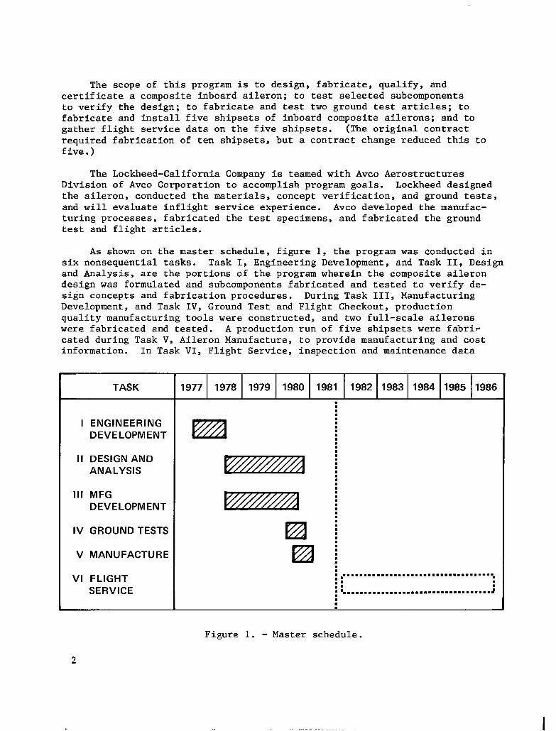
The scope of this program is to design, fabricate, qualify, and certificate a composite inboard aileron; to test selected subcomponents to verify the design; to fabricate and test two ground test articles; to fabricate and install five shipsets of inboard composite ailerons; and to gather flight service data on the five shipsets. (The original contract required fabrication of ten shipsets, but a contract change reduced this to five.)
The Lockheed-California Company is teamed with Avco Aerostructures Division of Avco Corporation to accomplish program goals. Lockheed designed the aileron, conducted the materials, concept verification, and ground tests, and will evaluate inflight service experience. Avco developed the manufac- turing processes, fabricated the test specimens, and fabricated the ground test and flight articles.
As shown on the master schedule, figure 1, the program was conducted in six nonsequential tasks. Task I, Engineering Development, and Task II, Design and Analysis, are the portions of the program wherein the composite aileron design was formulated and subcomponents fabricated and tested to verify de- sign concepts and fabrication procedures. During Task III, Manufacturing Development, and Task IV, Ground Test and Flight Checkout, production quality manufacturing tools were constructed, and two full-scale ailerons were fabricated and tested. A production run of five shipsets were fabri+ cated during Task V, Aileron Manufacture, to provide manufacturing and cost information. In Task VI, Flight Service, inspection and maintenance data
TASK 1977 1978 1979 1980 1981 1982 1983 1984 1985 1986 . : .
I ENGINEERING :
DEVELOPMENT : : . :
II DESIGN AND : ANALYSIS :
: .
I : Ill MFG :
DEVELOPMENT : :
IV GROUND TESTS
V MANUFACTURE
VI FLIGHT SERVICE
I
: . . . . . . . . . . . . . . . . . . . . . . . . . . . . . . . . . . . . . :: :: :
. . . . . . . . . . . . . . . . . . . . . . . . . . . . . . . . . ..J :
Figure 1. - Master schedule.
2
will be gathered on the five shipsets to assess their potential for econom- ical operation in routine service. The work performed during this program is intended to provide the data required to progress toward a production commitment.
This report summarizes the major technical achievements of the program. Additional detailed information pertaining to the various tasks within the program may be found in References 1 through 4.
MEASUREMENT VALUES
All measurement values in this technical report are expressed in the International System of Units and customary units. Customary units are used for the principal measurements and calculations.
COMPOSITE AILERON DESIGN
General Description
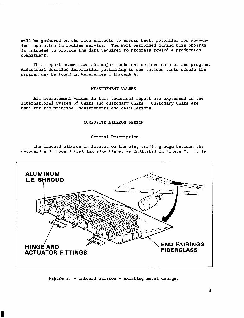
The inboard aileron is located on the wing trailing edge between the outboard and inboard trailing edge flaps, as indicated in figure 2. It is
ALUMINUM L.E. SHROUD
er’n ‘^‘SINGS \ EIYU rnln FIBEF-’ ’ HINGE AND / -
ACTUATOR FITTINGS
Figure 2. - Inboard aileron - existing metal design.
3
supported from the wing at two hinge points and is actuated by three hydraulic actuators. It is a wedge-shaped, one-cell box, thinning slightly from root to tip. At the front spar the aileron is 2337 mm (92 in.) in length and approxi- mately 254 mm (10 in.) deep. The width of the aileron is 1270 mm (50 in.).
The current aluminum aileron, shown in figure 2, consists of a front spar, a rear spar, and upper and lower skins, joined by three hinge ribs and fifteen intermediate and end ribs. A trailing edge wedge, leading edge shroud, and end fairings complete the assembly.
Design Criteria
The approach used for determining the composite aileron design concept and materials was to define the design criteria, create alternate designs, con- duct comparative tests, evaluate the alternatives against the criteria, and se- lect and implement the best alternative. A brief description of the criteria established for the Advanced Composite Aileron (ACA) is presented below:
l The ACA must be a direct replacement for the current aileron in form, fit and function.
l A minimum of 20 percent weight savings must be obtained.
l The ACA must be cost competitive with the existing aileron on a production basis.
l Materials selected for the ACA must not be severely degraded by environmental effects such as temperature r219.3 K(-65'F) to 335.4 K (180°F)] or moisture (1 percent by weight minimum).
Aileron external loads are related to hinge moment capabilities. Deflection of the aileron causes an airload hinge moment which is reacted by the actuators. Larger deflections give larger airloads until the maximum hinge moment capable of being reacted by the actuators is reached. In addition to airloads, the aileron must be designed to withstand acoustic loading up to 135 dB/Hz.
Typical of secondary structural components, the aileron is not a strength critical component. Instead its design is governed by stiffness. The composite aileron must have the same torsional stiffness as the metal aileron to preclude self-induced vibrations.
The aileron structure is designed to be fail safe for limit flight loads in accordance with Federal Aviation Administration (FAA) requirements. Also it is designed not to separate from the aircraft after any one of several failure or jam conditions premised in FAA requirements.
4
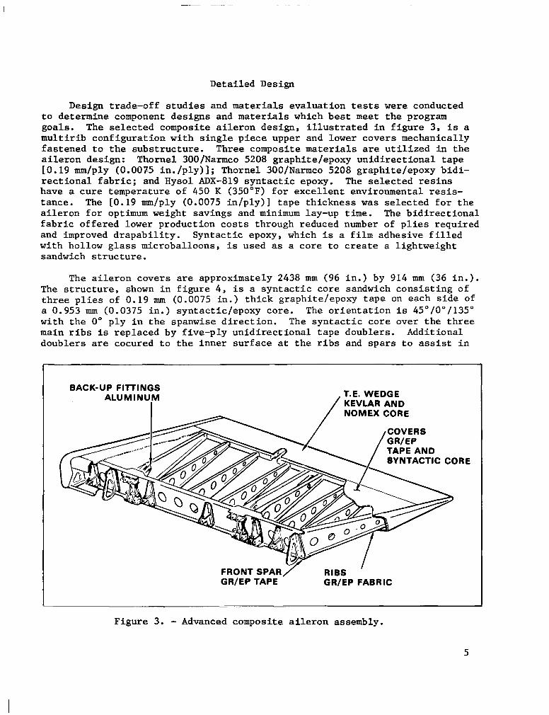
Detailed Design
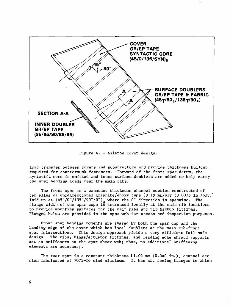
Design trade-off studies and materials evaluation tests were conducted to determine component designs and materials which best meet the program goals. The selected composite aileron design, illustrated in figure 3, is a multirib configuration with single piece upper and lower covers mechanically fastened to the substructure. Three composite materials are utilized in the aileron design: Thornel 300/Narmco 5208 graphite/epoxy unidirectional tape LO.19 mm/ply (0.0075 in./ply)]; Thornel 300/Narmco 5208 graphite/epoxy bidi- rectional fabric; and Hysol ADX-819 syntactic epoxy. The selected resins have a cure temperature of 450 K (350'F) for excellent environmental resis- tance. The [0.19 mm/ply (0.0075 in/ply)] tape thickness was selected for the aileron for optimum weight savings and minimum lay-up time. The bidirectional fabric offered lower production costs through reduced number of plies required and improved drapability. Syntactic epoxy , which is a film adhesive filled with hollow glass microballoons, is used as a core to create a lightweight sandwich structure.
The aileron covers are approximately 2438 mm (96 in.) by 914 mm (36 in.). The structure, shown in figure 4, is a syntactic core sandwich consisting of three plies of 0.19 mm (0.0075 in.) thick graphite/epoxy tape on each side of a 0.953 mm (0.0375 in.) syntactic/epoxy core. The orientation is 45"/0"/135" with the 0" ply in the spanwise direction. The syntactic core over the three main ribs is replaced by five-ply unidirectional tape doublers. Additional doublers are cocured to the inner surface at the ribs and spars to assist in
BACK-UP I ALI
FllTlNGS
U”‘NUIM / T.E. WEDGE KEVLAR AND
IRE
FRONT SPAR/ RIBS ’ GR/EP TAPE GR/EP FABRIC
Figure 3. - Advanced composite aileron assembly.
5
SYNTACTIC CORE SYNTACTIC CORE (45/O/l 35/SY N)s (45/O/l 35/SY N)s
SURFACE DOUBLERS SURFACE DOUBLERS GWEP TAPE 6 FABRIC GR/EP TAPE 6 FABRIC
5$9+/l 36T/goF) 5$9+/l 36T/goF)
SECTION A-A SECTION A-A
INNER DOUBL INNER DOUBL GR/EP TAPE GR/EP TAPE (95/85/90/85/95) (95/85/90/85/95)
Figure 4. - Aileron cover design.
load transfer between covers and substructure and provide thickness buildup required for countersunk fasteners. Forward of the front spar datum, the syntactic core is omitted and inner surface doublers are added to help carry the spar bending loads near the main ribs.
The front spar is a constant thickness channel section constructed of ten plies of unidirectional graphite/epoxy tape LO.19 mm/ply (0.0075 in./ply)] laid up at (45"/0"/135"/90"/0") where the 0" direction is spanwise. The flange width of the spar caps is" increased locally at the main rib locations to provide mounting surfaces for the main ribs and rib backup fittings. Flanged holes are provided in the spar web for access and inspection purposes.
Front spar bending moments are shared by both the spar cap and the leading edge of the cover which has local doublers at the main rib-front spar intersections. This design approach yields a very efficient fail-safe design. The ribs, hinge/actuator fittings, and leading edge shroud supports act as stiffeners on the spar shear web; thus, no additional stiffening elements are necessary.
The rear spar is a constant thickness El.02 mm (0.040 in.)] channel sec- tion fabricated of 7075-T6 clad aluminum. It has aft facing-flanges to which
both the covers and trailing edge wedge are attached. Aluminum was selected for this component because utilization of composites would be too costly for the small amount of weight saved.
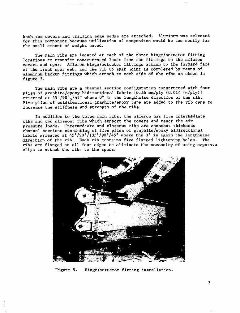
The main ribs are located at each of the three hinge/actuator fitting locations to transfer concentrated loads from the fittings to the aileron covers and spar. Aileron hinge/actuator fittings attach to the forward face of the front spar web, and the rib to spar joint is completed by means of aluminum backup fittings which attach to each side of the ribs as shown in figure 5.
The main ribs are a channel section configuration constructed with four plies of graphite/epoxy bidirectional fabric IO'.36 mm/ply (0.014 in/ply)] oriented at 45'/90°2/45“ where 0" is the lengthwise direction of the rib. Five plies of unidirectional graphite/epoxy tape are added to the rib caps to increase the stiffness and strength of the ribs.
In addition to the three main ribs, the aileron has five intermediate ribs and two closeout ribs which support the covers and react the air pressure loads. Intermediate and closeout ribs are constant thickness channel sections consisting of five plies of graphite/epoxy bidirectional fabric oriented at 45"/9O"/135"/9O"/45" where the 0" is again the lengthwise direction of the rib. Each rib contains five flanged lightening holes. The ribs are flanged on all four edges to eliminate the necessity of using separate clips to attach the ribs to the spars.
Figure 5. - Hinge/actuator fitting installation.
7
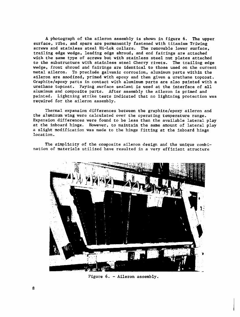
A photograph of the aileron assembly is shown in figure 6. The upper surface, ribs, and spars are permanently fastened with titanium Triwing screws and stainless steel Hi-Lok collars. The removable lower surface, trailing edge wedge, leading edge shroud , and end fairings are attached with the same type of screws but with stainless steel nut plates attached to the substructure with stainless steel Cherry rivets. The trailing edge wedge, front shroud and fairings are identical to those used on the current metal aileron. To preclude galvanic corrosion, aluminum parts within the aileron are anodized, primed with epoxy and then given a urethane topcoat. Graphite/epoxy parts in contact with aluminum parts are also painted with a urethane topcoat. Faying surface sealant is used at the interface of all aluminum and composite parts. After assembly the aileron is primed and painted. Lightning strike tests indicated that no lightning protection was required for the aileron assembly.
Thermal expansion differences between the graphite/epoxy aileron and the aluminum wing were calculated over the operating temperature range. Expansion differences were found to be less than the available lateral play at the inboard hinge. However, to maintain the same amount of lateral play a slight modification was made to the hinge fitting at the inboard hinge location.
The simplicity of the composite aileron design and the unique combi- nation of materials utilized have resulted in a very efficient structure
Figure 6. - Aileron assembly.
8
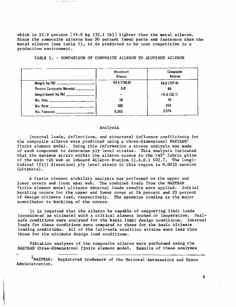
which is 22.9 percent L14.6 kg (32.1 lb)] lighter than the metal aileron. Since the composite aileron has 50 percent fewer parts and fasteners than the metal aileron (see table l), it is predicted to be cost competitive in a production environment.
TABLE 1. - COMPARISON OF COMPOSITE AILERON TO ALUMINUM AILERON
Weight, kg.@)
Percent Composite Material
Weight Saved, kg (lb)
No. Ribs
No. Parts
No. Fasteners
Aluminum Aileron
63.4 (139.9)
5.8
18
398
5,253
Composite Aileron
48.9 (107.8)
64
14.6 (32.1)
10
205
2,574
Analysis
Internal loads, deflections, and structural influence coefficients for the composite aileron were predicted using a three-dimensional NASTRARl finite element model. Using this information a stress analysis was made of each component to determine ply level strains. This analysis indicated that the maximum strain within the aileron occurs in the +45" fabric plies of the main rib web at Inboard Aileron Station (I.A.S.) 102.7. The longi- tudinal (fill direction) ply level strain in this region is 0.0035 tension (ultimate).
A finite element stability analysis was performed on the upper and lower covers and front spar web. The combined loads from the NASTRAN finite element model ultimate internal loads results were applied. Initial buckling occurs for the upper and lower cover at 24 percent and 20 percent of design ultimate load, respectively. The spanwfse loading is the major contributor to buckling of the covers.
It is required that the aileron be capable of supporting limit loads (considered as ultimate) with a critical element broken or inoperative. Fail- safe conditions were analyzed for the basic limit design conditions. Internal loads for these conditions were compared to those for the basic ultimate loading conditions. All of the fail-safe condition strains were less than those for the ultimate design load conditions.
Vibration analyses of the composite aileron were performed using the NASTRAN three-dimensional finite element model. Results of these analyses
INASTRAN: Registered trademark of the National Aeronautics and Space Administration.
9
were compared to measured vibration characteristics of the metal aileron and it was concluded that the behavior of the composite aileron was similar to the metal aileron.
VERIFICATION OF STRUCTURAL INTEGRITY
Design Data
Fundamental material behavior was determined by a large number of coupon tests at several environmental conditions. Ply level data for graphite/ epoxy tape and fabric were obtained for use in the analytical predictions of laminate behavior. Laminates representing the covers, ribs, and front spar were tested to verify material behavior and to establish strength adjustment factors for environmental conditions, notches, and damage tolerance. In addition, specimens representing various mechanical joint areas in the ACA design were tested to verify joint strength.
The environmental extremes for the aileron are temperature [219.3 K (-65OF) to 355.4 K (180°F)] and various fluids including jet fuel, hydraulic fluid, paint stripper and water. Screening tests were conducted to determine which of the above environmental extremes caused the greatest degradation of mechanical properties. These conditions were then used for testing to estab- lish design allowables. Examples of coupon data for the ply level properties and typical laminate data for Thornel 300/5208 bidirectional fabric (24X23 - 8HS) are given in tables 2 and 3. Note that typically the 219.3 K (-65°F) dry condition results in the greatest reduction in tensile strength and that the 355.4 K (180'F) wet (one percent moisture by weight) condition is the most severe for compression loading. For the notched laminate tests a 4.76 mm (3/16 in.) diameter open hole was used since this is the most common fastener size utilized in the aileron assembly.
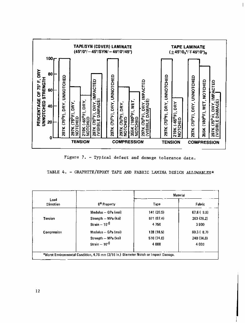
Defect and damage tolerance of the aileron was determir.ed by conducting tests on representative laminates. Defects and damages investigated included voids, notches, and impact damage. Information from these tests was used to establish the manufacturing accept/reject criteria and laminate design allowables. Typical defect and damage tolerance data for the ACA cover laminate and a graphite/epoxy tape laminate are presented in figure 7. Results of all of the tests indicated that for tensile loads an open hole degraded the strength much more than a void or impact damage. For compression loads, impact damage caused the greatest reduction in strength.
For the graphite/epoxy composite materials used for the aileron, the design allowables were established to reflect the worst environmental con- dition in combination with the largest defect allowed by the accept/reject criteria, a 4.76 mm (3/16 in.) diameter open hole, or impact damage which cannot be located by visual inspection. All of the laminate data were statistically analyzed and design allowables established. Allowables for T300/5208 tape and fabric are presented in table 4.
10
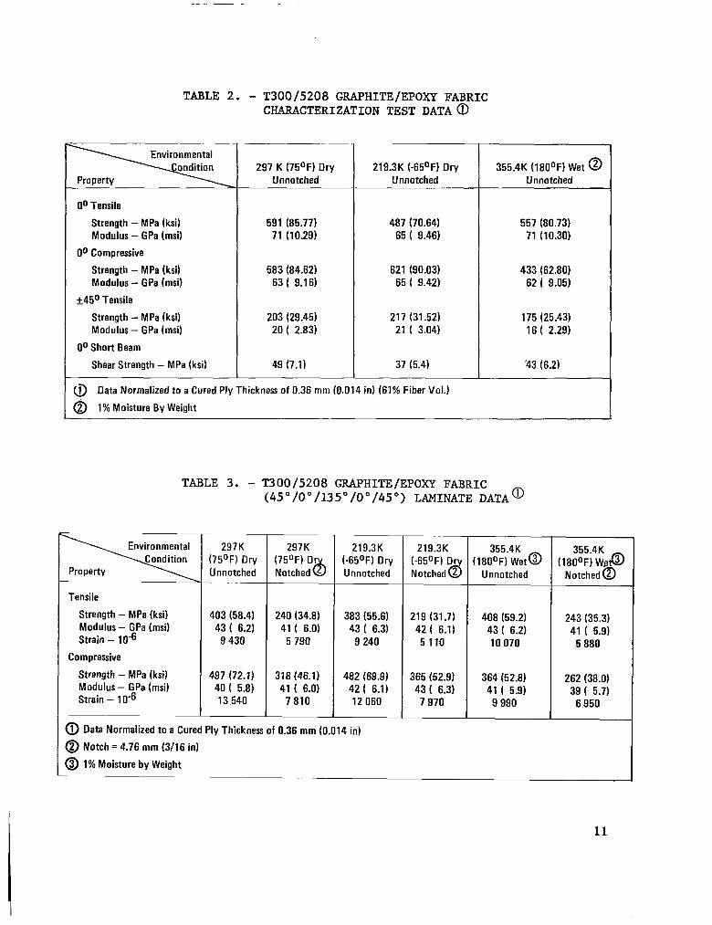
TABLE 2. - T300/5208 GRAPHITE/EPOXY FABRIC CHARACTERIZATION TEST DATA@
O” Tensile
Strength - MPa (ksi) Modulus - GPa (msi)
O” Compressive
Strength - MPa (ksi) Modulus - GPa (msi)
+45O Tensile
Strength - MPa (ksi) Modulus - GPa (msi)
O” Short Beam
Shear Strength - MPa (ksi)
297 K (75OF) Dry Unnotched
591 (85.77) 71 (10.29)
583 (84.62) 63 ( 9.16)
203 (29.45) 20 ( 2.83)
49 (7.1)
219.3K (-65OF) Dry Unnotched
487 (70.64) 65 ( 9.46)
621 (90.03) 65 ( 9.42)
217 (31.52) 21 ( 3.04)
37 (5.4)
@ Data Normalized to a Cured Ply Thickness of 0.36 mm (0.014 in) (61% Fiber Vol.)
@ 1% Moisture By Weight
355.4K (18OOF) Wet @ Unnotched
557 (80.73) 71 (10.30)
433 (62.80) 62 I 9.05)
175 (25.43) 16 ( 2.29)
‘43 (6.2)
Tensile
Strength - MPa (ksi) Modulus - GPa (msi) Strain - lo6
Compressive
Strength - MPa (ksi) Modulus - GPa (msi) Strain - 1 O6
TABLE 3. - T300/5208 GRAPHITE/EPOXY FABRIC (45"/0"/135"/0"/45") LAMINATE DATAa
297K (75OF) Dry Unnotched
403 (58.4) 43 ( 6.2)
9 430
497 (72.1) 40 ( 5.8) 13,540
297K (75OF) Or Notched b
240 (34.8) 41 ( 6.0)
5 790
318 (46.1) 41 ( 6.0)
7 810
219.3K (-650~) Dry Unnotched
383 (55.6) 43 ( 6.3)
9 240
482 (69.9) 42 ( 6.1) 12 060
219.3K (-650~) Dr Notched 2 d
219 (31.7) 42 ( 6.1) 5 110
365 (52.9) 43 ( 6.3)
7 970
1803r?)~t~ Unnotched
408 (59.2) 43 ( 6.2) 10 070
364 (52.8) 41 ( 5.9)
9 990
:1,Ei4L@ Notched @
-
243 (35.3) 41 ( 5.9)
5 880
262 (38.0) 39 ( 5.7)
6 950
@ Data Normalized to a Cured Ply Thickness of 0.36 mm (0.014 in)
0 Notch = 4.76 mm (3116 in)
@ 1% Moisture by Weight
11
TAPE/SYN (COVER) LAMINATE (45”/0”/ - 4WSY N/ - 45”/0”/45”)
TAPE LAMINATE ( + 45”/03”/ T 45VO”)s
TENSION COMPRESStON TENSION COMPRESSION
Figure 7. - Typical defect and damage tolerance data.
TABLE 4. - GRAPHITE/EPOXY TAPE AND FABRIC LAMINA DESIGN ALLOWABLES*
Material
Load Direction O” Property Tape
Modulus - GPa (msi) 141 (20.5)
Tension Strength - MPa (ksi) 671 (97.4)
Strain - 1 O6 4 750
Compression Modulus - GPa (msi) 128 (18.5)
Strength - MPa (ksi) 510 (74.0)
Strain - 1 O6 4 000
*Worst Environmental Condition, 4.76 mm (3/16 in.). Diameter Notch or Impact Damage.
Fabric
67.6 ( 9.8)
263 (28.2)
3 900
60.3 ( 8.7)
240 (34.8)
4 000
12
Concept Verification
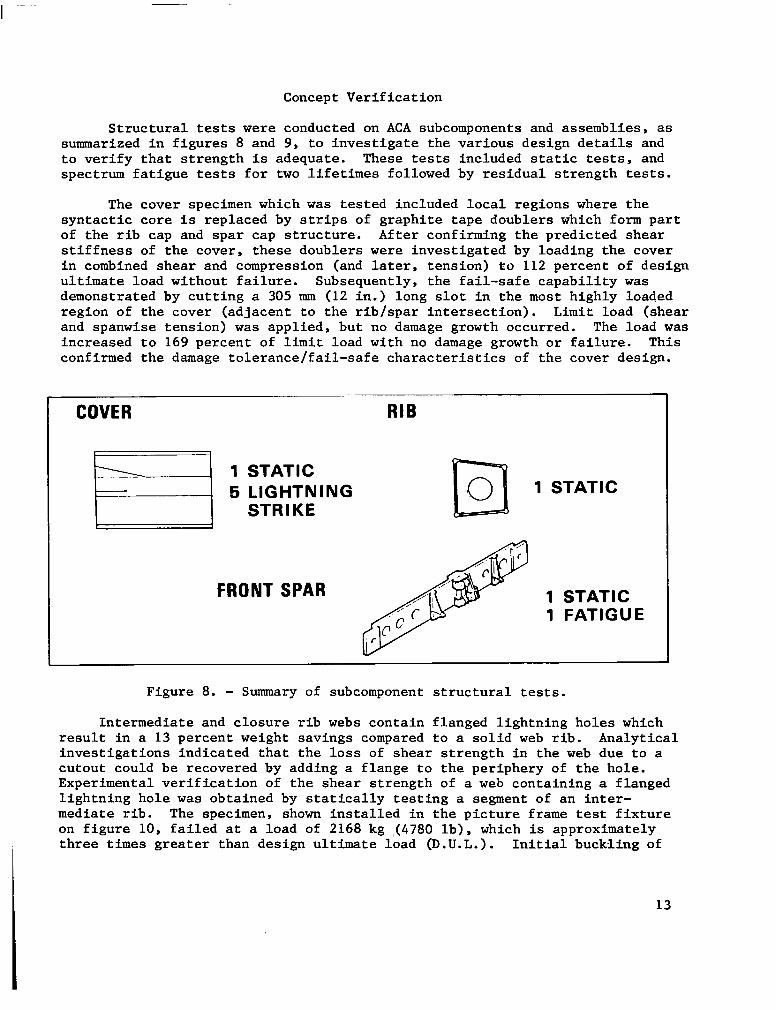
Structural tests were conducted on ACA subcomponents and assemblies, as summarized in figures 8 and 9, to investigate the various design details and to verify that strength is adequate. These tests included static tests, and spectrum fatigue tests for two lifetimes followed by residual strength tests.
The cover specimen which was tested included local regions where the syntactic core is replaced by strips of graphite tape doublers which form part of the rib cap and spar cap structure. After confirming the predicted shear stiffness of the cover, these doublers were investigated by loading the cover in combined shear and compression (and later, tension) to 112 percent of design ultimate load without failure. Subsequently, the fail-safe capability was demonstrated by cutting a 305 mm (12 in.) long slot in the most highly loaded region of the cover (adjacent to the rib/spar intersection). Limit load (shear and spanwise tension) was applied, but no damage growth occurred. The load was increased to 169 percent of limit load with no damage growth or failure. This confirmed the damage tolerance/fail-safe characteristics of the cover design.
COVER RIB
1 STATIC 5 LIGHTNING 1 STAT
STRIKE
FRONT SPAR
IC
Figure 8. - Summary of subcomponent structural tests.
Intermediate and closure rib webs contain flanged lightning holes which result in a 13 percent weight savings compared to a solid web rib. Analytical investigations indicated that the loss of shear strength in the web due to a cutout could be recovered by adding a flange to the periphery of the hole. Experimental verification of the shear strength of a web containing a flanged lightning hole was obtained by statically testing a segment of an inter- mediate rib. The specimen, shown installed in the picture frame test fixture on figure 10, failed at a load of 2168 kg (4780 lb), which is approximately three times greater than design ultimate load (D.U.L.). Initial buckling of
13
RIB/SPAR/FTG BOX ASSEMBLY
2 STATIC 1 FATIGUE
FATIGUE
GROUND TES ARTICLES 1 STATIC
1 DAMAGE GROWTH/ FAILSAFE
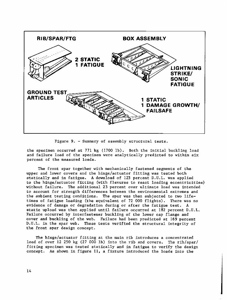
Figure 9. - Summary of assembly structural tests.
the specimen occurred at 771 kg (1700 lb). Both the initial buckling load and failure load of the specimen were analytically predicted to within six percent of the measured loads.
The front spar together with mechanically fastened segments of the upper and lower covers and the hinge/actuator fitting was tested both statically and in fatigue. A download of 123 percent D.U.L. was applied to the hinge/actuator fitting (with flexures to react loading eccentricities) without failure. The additional 23 percent over ultimate load was intended to account for strength differences between the environmental extremes and the ambient testing conditions. The spar was then subjected to two life- times of fatigue loading (the equivalent of 72 000 flights). There was no evidence of damage or degradation during or after the fatigue test. A static upload was then applied until failure occurred at 182 percent D.U.L. Failure occurred by interfastener buckling of the lower cap flange and cover and buckling of the web. Failure had been predicted at 169 percent D.U.L. in the spar web. These tests verified the structural integrity of the front spar design concept.
The hinge/actuator fitting at the main rib introduces a concentrated load of over 12 250 kg (27 000 lb) into the rib and covers. The rib/spar/ fitting specimen was tested statically and in fatigue to verify the design concept. As shown in figure 11, a fixture introduced the loads into the
14
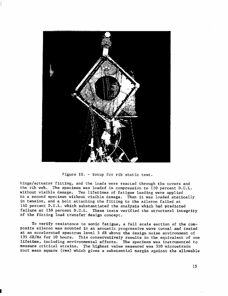
Figure 10. - Setup for rib static test.
hinge/actuator fitting, and the loads were reacted through the covers and the rib web. The specimen was loaded in compression to 110 percent D.U.L. without visible damage. Two lifetimes of fatigue loading were applied to a second specimen without visible damage. Then it was loaded statically in tension, and a bolt attaching the fitting to the aileron failed at 140 percent D.U.L. which substantiated the analysis which had predicted failure at 139 percent D.U.L. These tests verified the structural integrity of the fitting load transfer design concept.
To verify resistance to sonic fatigue, a full scale section of the com- posite aileron was mounted in an acoustic progressive wave tunnel and tested at an accelerated spectrum level 5 dB above the design noise environment of 135 dB/Hz for 10 hours. This conservatively results in the equivalent of one lifetime, including environmental effects. The specimen was instrumented to measure critical strains. The highest value measured was 310 microstrain root mean square (rms> which gives a substantial margin against the allowable
15
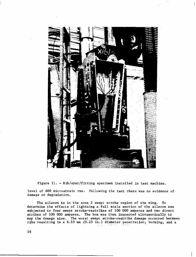
Figure 11. - Rib/spar/fitting specimen installed in test machine.
level of 600 microstrain rms. Following the test there was no evidence of damage or degradation.
The aileron is in the zone 2 swept stroke region of the wing. To determine the effects of lightning a full scale section of the aileron was subjected to four swept stroke-restrikes of 100 000 amperes and two direct strikes of 200 000 amperes. The box was then inspected ultrasonically to map the damage size. The worst swept stroke-restrike damage occurred between ribs resulting in a 6.35 mmAO.25 in.) diameter penetration, burning, and a
16
delamination region of 380 mm (15 in.) by 76.2 mm (3 in.). The damage was within the limits of the fail-safe criteria and repairable.
Ground Tests
The first set of ground tests consisted of vibration and stiffness tests for both a metal and composite aileron to enable a relative comparison. The aileron was mounted by the hinges in a reaction test frame, and various actuator configurations were simulated with adjustable links. An electro- dynamic shaker, attached by a bonded pad to the outboard closeout rib, was used to apply various frequencies and amplitudes to the aileron. A reference accelerometer together with a roving accelerometer were used to monitor the frequency responses summarized on table 5 below. Since the frequencies were so comparable, flutter-free performance of the composite aileron was predicted.
A pair of actuators attached by pads to the rear spar were used to load the aileron to determine chordwise bending and torsional stiffness. The rotation and deflection at nine points on the aileron surface were measured both optically and with linear transducers. The average chordwise bending stiffness of the composite aileron was 27 percent less than that of the metal aileron.
Torsional stiffness testing produced some unexpected results. The composite aileron stiffness was multilinear and generally increased as the load increased. Furthermore, the stiffness increased during each of three, or four, load applications; finally stabilizing after four, or five, load applications. To test the hypothesis that this phenomenon might be due to the clearance fit of the fasteners used for assembly the load was reversed. That is, the load was applied at station 57.1 and reacted at station 102.7 instead of vice versa. The initial loading resulted in 20 percent less stiffness than in the other direction. However, after four more load appli- cations the stiffness stabilized at 96 percent of the stiffness in the other direction. To further test the fastener fit hypothesis, the second ground test article was tested in the same manner. It was known that the fastener fit for the second article was better than for the first article due to improved hole drilling methods. The fastener fit hypothesis was
TABLE 5. - FREQUENCY COMPARISON
Mode ,,I Actuator Condition 1 Metal Freqrncv Composite
Flapping
Flapping
Flapping
Torsion
17
confirmed by the fact that its stiffness was higher, had little variation with load magnitude, and stabilized after only three load cycles. The torsional stiffnesses of the three ailerons tested are summarized in table 6.
Following the stiffness tests , pads were bonded to the upper surface over ribs and spars to introduce the loads from four hydraulic cylinders through a whiffle tree system as shown on figure 12. The four hydraulic cylinders were computer-controlled through a hydraulic servo system to apply the correct proportion of loading throughout the load range. The aileron actuators were simulated with three instrumented links that were adjustable to simulate the angular position of the aileron. Strains were monitored with 27 axial or rosette strain gages. Deflections were monitored with eight linear transducers.
Two loading conditions were tested. Condition 4 loads, representing the 12" down aileron position, were applied to 124 percent D.U.L. without failure. The 24 percent factor on condition 4 loads resulted in loads on the hinge/actuator fitting fasteners equal to the design ultimate load for another loading condition that was not tested. There was no visible damage from this test.
The condition 1 loads, representing the 20" up aileron position, were applied to 117 percent D.U.L. without failure. The 17 percent factor accounted for the strength differences between the environmental extremes and the ambient testing conditions. The condition 1 loads were increased to failure which occurred at 139 percent D.U.L. Failure was a result of postbuckling of the webs of the hinge and actuator backup ribs at stations 102.7 and 107.1.
A second ground test article was tested to verify the damage tolerance and fail-safe characteristics of the composite aileron. Four critical locations were selected for inflicting damage: the upper cover was impacted to obtain visible damage, the main rib cap was partially severed at a fastener, the front spar web was impacted to obtain visible damage, and the
TABLE 6. - TORSIONAL STIFFNESS COMPARISONS
Torsional Stiffness IO3 N-m2 (IO6 lb-in*)
Required
Predicted
Metal
861 (300)
1068 (373)
Measured I 1105 (385)
GTA I GTA 2
861 (300)
1059 (369)
1079 (376)
18
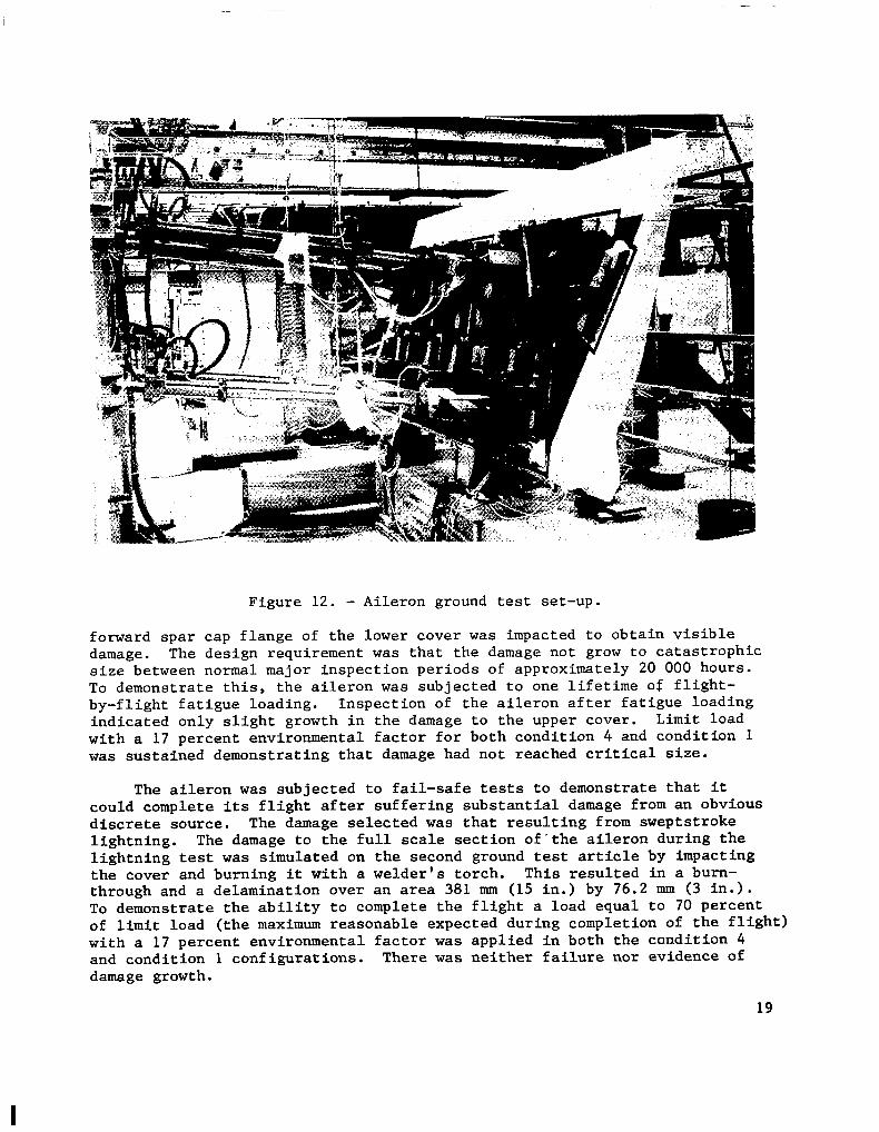
Figure 12. - Aileron ground test set-up.
forward spar cap flange of the lower cover was impacted to obtain visible damage. The design requirement was that the damage not grow to catastrophic size between normal major inspection periods of approximately 20 000 hours. To demonstrate this, the aileron was subjected to one lifetime o# flight- by-flight fatigue loading. Inspection of the aileron after fatigue loading indicated only slight growth in the damage to the upper cover. Limit load with a 17 percent environmental factor for both condition 4 and condition 1 was sustained demonstrating that damage had not reached critical size.
The aileron was subjected to fail-safe tests to demonstrate that it could complete its flight after suffering substantial damage from an obvious discrete source. The damage selected was that resulting from sweptstroke lightning. The damage to the full scale section of-the aileron during the lightning test was simulated on the second ground test article by impacting the cover and burning it with a welder's torch. This resulted in a burn- through and a delamination over an area 381 mm (15 in.) by 76.2 mm (3 in.). To demonstrate the ability to complete the flight a load equal to 70 percent of limit load (the maximum reasonable expected during completion of the flight) with a 17 percent environmental factor was applied in both the condition 4 and condition 1 configurations. There was neither failure nor evidence of damage growth.
19
I
Following all these tests, the aileron was loaded to failure to determine its residual static strength. Failure occurred at 130 percent of design ultimate load in essentially the same mode as occurred with the undamaged static test article.
The successful conclusion of the static tests and the damage tolerance and fail-safe tests demonstrated the structural integrity of the composite aileron.
Flight Test
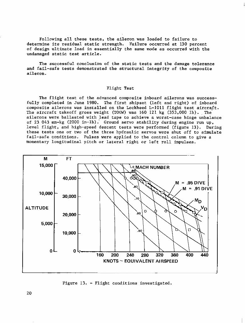
The flight test of the advanced composite inboard ailerons was success- fully completed in June 1980. The first shipset (left and right) of inboard composite ailerons was installed on the Lockheed L-1011 flight test aircraft. The aircraft takeoff gross weight (TOGW) was 160 121 kg (353,000 lb). -The ailerons were ballasted with lead tape to achieve a worst-case hinge unbalance of 23 043 mm-kg (2000 in-lb): Ground servo stability during engine run up, level flight, and high-speed descent tests were performed (figure 13). During these tests one or two of the three hydraulic servos were shut off to simulate fail-safe conditions. Pulses were applied to the control column to give a momentary longitudinal pitch or lateral right or left roll impulses.
M FT
15,000 -
ALTITUDE
20,000
5,000 -
10,000
M = .95 DIVE
KNOTS - EQUIVALENT AIRSPEED
Figure 13. - Flight conditions investigated.
The advanced composite aileron response was somewhat better than the metal aileron during ground engine run up, and the damping characteristics of the composite aileron were comparable to the metal aileron during all tests. The composite aileron was flutter-free throughout the flight envelope.
AILERON FABRICATION
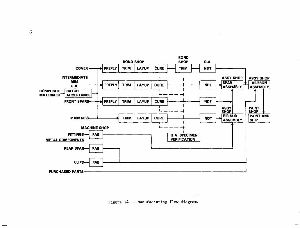
Tooling and processing parameters were developed for the composite aileron. These procedures were used to manufacture five shipsets of these ailerons in a production environment. A flow diagram defining the basic manufacturing operations necessary to perform this task is shown in figure 14.
TOOLING
Prior to the initiation of the production composite detail fabrication effort an evaluation was made of male vs female tooling philosophy for producing channel configuration details such as spars and ribs. The effec- tiveness of each tooling concept was evaluated for tool cost (recurring and non-recurring), detail dimensional repeatability, cost, and physical and mechanical property consistency. The male tool concept was chosen because less tool development was required, lower tool fabrication and maintenance cost, lower composite fabrication costs and the necessary dimensional repeatability could be maintained on fabricated details.
PROCESS DEVELOPMENT
The processes developed for fabrication of the graphite parts utilized the following significant achievements: 1) a common cure cycle for all details, 2) use of low resin content material, 3) incorporation of a no trim technique of cure. In addition, the assembly techniques developed showed that composite details can be drilled with hand tools at a production rate and maintain the high quality standards required.
DETAIL FABRICATION
The 13 graphite composite parts required for each composite aileron were fabricated in production environment using the developed tools and processes.
21
COMPOSITE MATERIALS
BOND BOND SHOP SHOP Q.A.
LAYUP tXJF?E TRIM I I
INTERMEDIATE --- ASSY SHOP RIBS Q.A.
BATCH ACCEPTANCE ---
FRONT SPARS- PREPLY TRIM LAYUP CURE
L 4 ASSY -a- SHOP
MAIN RIBS A RIB SUB ASSEMBLY
4
1 ASSY SHOP
MACHINE SHOP
FITTINGS
METAL COMPONENTS
REAR SPAR FAB
CLIPS FAB
PURCHASED PARTS I
Figure 14. - Manufacturing flow .diagram.
Ribs
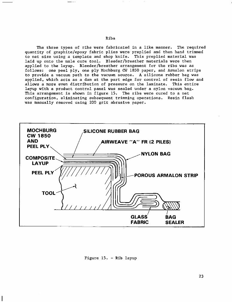
The three types of ribs were fabricated in a like manner. The required quantity of graphite/epoxy fabric plies were preplied and then hand trimmed to net size using a template and shop knife. This preplied material was laid up onto the male cure tool. Bleeder/breather materials were then applied to the layup. Bleeder/breather arrangement for the ribs was as follows: one peel ply, one ply Mochburg CW 1850 paper, and Armalon strips to provide a vacuum path to the vacuum source. A silicone rubber bag was applied, which acts as a dam at the part edge for control of resin flow and allows a more even distribution of pressure on the laminate. This entire layup with a product control panel was sealed under a nylon vacuum bag. This arrangement is shown in figure 15. The ribs were cured to a net configuration, eliminating subsequent trimming operations. Resin flash was manually removed using 200 grit abrasive paper.
MOCHBURG CW 1850 AND PEEL PLY, /
SILICONE RUBBER BAG
AIRWEAVE “A” FR (2 PILES) /
I I GLASS BAG FABRIC SEALER
STRIP
Figure 15. - Rib layup
23
Spar
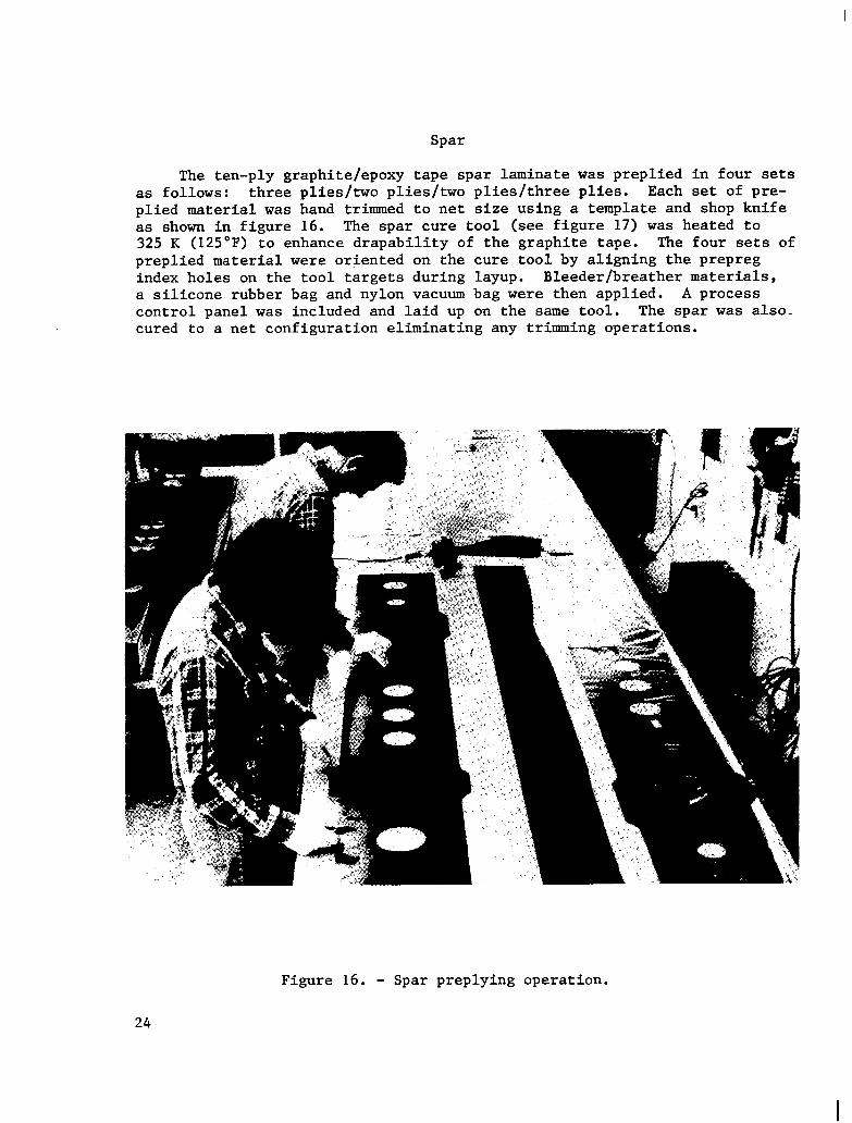
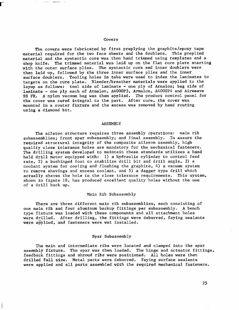
The ten-ply graphite/epoxy tape spar laminate was preplied in four sets as follows: three plies/two plies/two plies/three plies. Each set of pre- plied material was hand trimmed to net size using a template and shop knife as shown in figure 16. The spar cure tool (see figure 17) was heated to 325 K (125°F) to enhance drapability of the graphite tape. The four sets of preplied material were oriented on the cure tool by aligning the prepreg index holes on the tool targets during layup. Bleeder/breather materials, a silicone rubber bag and nylon vacuum bag were then applied. A process control panel was included and laid up on the same tool. The spar was also- cured to a net configuration eliminating any trimming operations.
Figure 16. - Spar preplying operation.
24
r
Covers
The covers were fabricated by first preplying the graphite/epoxy tape material required for the two face sheets and the doublers. This preplied material and the syntactic core was then hand trimmed using templates and a shop knife. The trimmed material was laid up on the flat cure plate starting with the outer surface plies. The syntactic core and inner doublers were then laid up, followed by the three inner surface plies and the inner surface doublers. Tooling holes in tabs were used to index the laminates to targets on the cure plate. Bleeder/breather materials were applied to the layup as follows: tool side of laminate - one ply of Armalon; bag side of laminate - one ply each of Armalon, A4000P3, Armalon, A4000P4 and Airweave SS FR. A nylon vacuum bag was then applied. The product control panel for the cover was cured integral to the part. After cure, the cover was mounted in a router fixture and the excess was removed by hand routing using a diamond bit.
ASSEMBLY
The aileron structure requires three assembly operations: main rib subassemblies; front spar subassembly; and final assembly. To assure the required structural integrity of the composite aileron assembly, high quality close tolerance holes are mandatory for the mechanical fasteners. The drilling system developed to maintain these standards utilizes a hand held drill motor equipped with: 1) a hydraulic cylinder to control feed rate, 2) a bushinged foot to stabilize drill bit and drill angle, 3) a coolant system for cooling and flushing the graphite, 4) a vacuum system to remove shavings and excess coolant, and 5) a dagger type drill which actually shaves the hole to the close tolerance requirements. This system, shown in figure 18, has produced excellent quality holes without the use of a drill back up.
Main Rib Subassembly
There are three different main rib subassemblies, each consisting of one main rib and four aluminum backup fittings per subassembly. A bench type fixture was loaded with these components and all attachment holes were drilled. After drilling, the fittings were deburred, faying sealants were applied, and fasteners were wet installed.
Spar Subassembly
The main and intermediate ribs were located and clamped into the spar assembly fixture. The spar was then loaded. The hinge and actuator fittings, feedback fittings and shroud ribs were positioned. All holes were then drilled full size. Metal parts were deburred. Faying surface sealants were applied and all parts assembled with the required mechanical fasteners.
25
Figure 17. - Spar preply template and cure tool.
Final Assembly
The final assembly of the aileron consists of the spar subassembly, rear spar, upper and lower covers, trailing edge, end fairings and leading edge shroud. The assembly sequence was as follows:
1. Load front spar assembly, rear spar and closeout ribs
2. Drill attach holes through rear spar and ribs
3. Load upper cover and drill attach holes
4. Remove upper cover, load lower cover and drill attach holes
5. Remove lower cover and permanently fasten upper cover
26
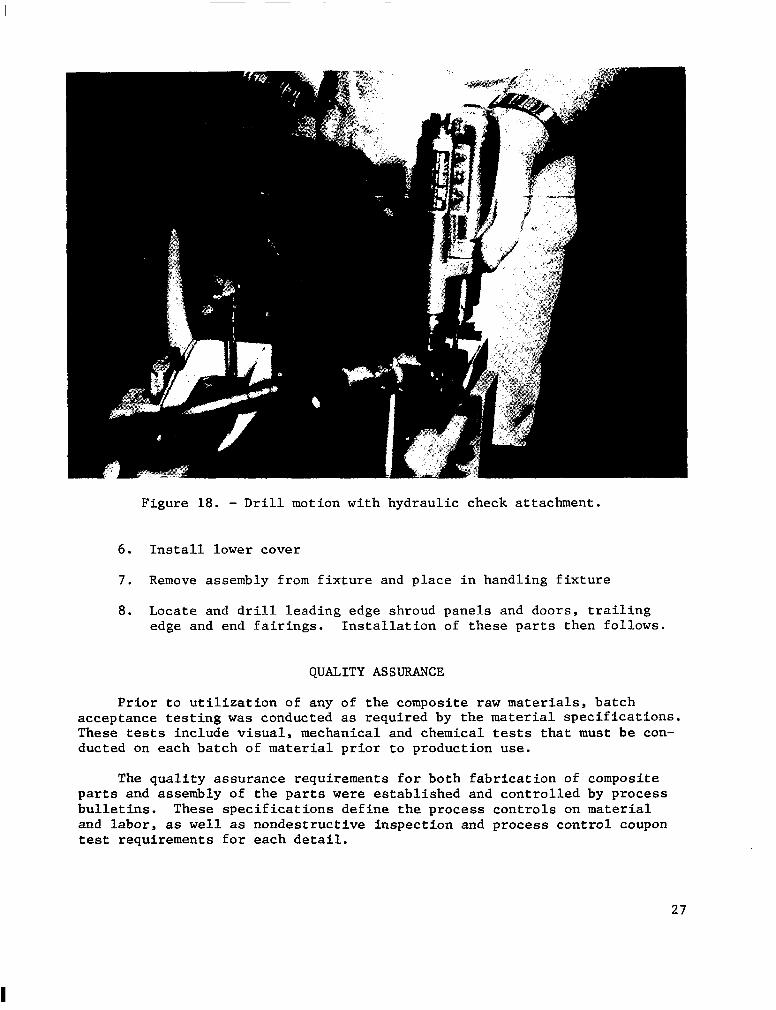
Figure 18. - Drill motion with hydraulic check attachment.
6. Install lower cover
7. Remove assembly from fixture and place in handling fixture
8. Locate and drill leading edge shroud panels and doors, trailing edge and end fairings. Installation of these parts then follows.
QUALITY ASSURANCE
Prior to utilization of any of the composite raw materials, batch acceptance testing was conducted as required by the material specifications. These tests include visual, mechanical and chemical tests that must be con- ducted on each batch of material prior to production use.
The quality assurance requirements for both fabrication of composite parts and assembly of the parts were established and controlled by process bulletins. These specifications define the process controls on material and labor, as well as nondestructive inspection and process control coupon test requirements for each detail.
27
Each part had thickness measurement determinations and was ultrasonically inspected for voids. The process control panel for each part was cut into specimens and tested for resin content, void content and short beam shear properties.
Manufacturing routing sheets were used throughout the fabrication and assembly areas to provide work instructions to the latest engineering and specification requirements. The inspectors verify and document these oper- ations. Detail fabrication documentation includes: material batch acceptance logs, ply orientation and sequence, cure records, process control test results, ultrasonic inspection, and visual and dimensional inspection.
During assembly operations, the quality assurance inspectors check for part numbers, detail acceptance stamps, proper location and fitup as the assembly fixtures are loaded. After drilling and removal from the fixture, each hole was inspected for size, tolerance and quality. Any condition that could not be reworked in accordance with engineering requirements is placed on a Nonconforming Material Review (NMR) tag for disposition. In addition to the typical quality surveillance, the final assembiy of each aileron received FAA conformity inspection , which included supporting -data such as material acceptance logs, test results of each composite detail, weights and copies of all processed NMR tags.
MANUFACTURING COST
The manufacturing costs associated with the advanced composite aileron have been developed through three phases. The first phase, prior to fabri- cation consisted of a cost estimate of producing both the composite and metal aileron configuration based on previous experience. The second phase involved the tracking and documentation of the actual costs to manu- facture components of 12 composite ailerons. These data were used to determine the current cost of manufacturing composite ailerons. During the third phase, actual production data developed during phase two was used to establish a cost estimate for producing advanced composite ailerons. Further analysis compares the projected composite costs, assuming automated equipment and material costs currently being quoted, with the metal aileron.
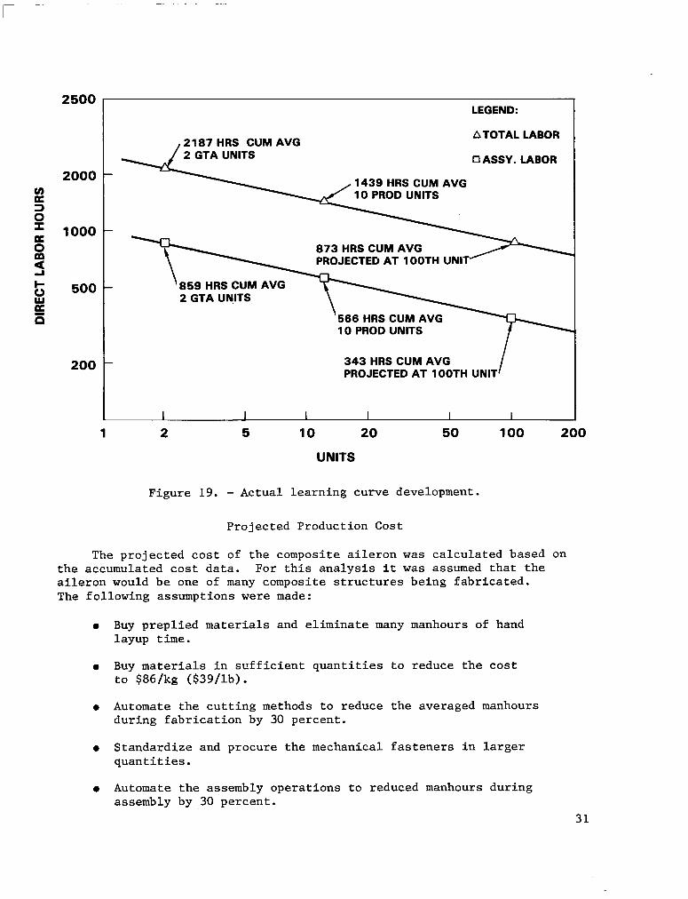
During the fabrication and assembly of two ground test articles (GTA's) and ten production ailerons, labor and material costs were tracked and compiled for the front spar, a main rib, anlntermediate rib, the upper cover, and assembly. From these documented data the estimated cost to produce an average GTA unit, the average estimated cost to produce an aileron, a projected improvement slope (learning curve), and the projected cost to produce 100 ailerons (using similar tooling, equipment and facilities) were computed.
28
A cost analysis, using the fabrication and assembly data developed on the composite ailerons, was conducted to compare the cost of composite aileron with the aluminum aileron.
Producibility Cost Analysis
An analysis was made to compare the costs of manufacturing the composite aileron and the sheet metal configuration. The composite aileron cost is based on the manufacturing data which were accumulated and documented. The corresponding costs for fabricating the sheet metal configuration were determined using a standard cost estimating methodology. The comparison, shown in table 7, was based on the following premises:
l Costs are stated in 1980 dollars
l Costs include recurring materials, production labor and quality assurance only
l Labor rates and material costs per AVCO study
l Labor calculated as a cumulative average of 100 units using the learning slopes experienced during fabricating and assembling advanced composite and sheet metal components (see figure 19).
l The recurring production materials and their corresponding costs are:
Graphite/Epoxy Tape $123/Q ($ 56/lb)
Fabric $lSO/kg ($ 68/lb)
$ 81/m2 ($7.50/ft2) Syntactic
This comparison demonstrates that the cost of the composite material is the major cost driver. The quantity of fasteners was reduced from over 5000 to less than 3000. However, in most instances, because of the need for material compatibility, the low-cost fasteners used in aluminum structure had to be replaced with more expensive titanium fasteners. In summary, the costs saved by eliminating fasteners and the corresponding reduced installation manhours were not sufficient to overcome the higher material and fastener costs. This situation will be partially remedied in the future through increased quantity procurement.
A comparison of the labor costs, including inspection, of the redesigned aileron components, shown as percentage of the total, are given in table 8. These data show that the major cost driver in labor is installing the fasteners during final assembly.
29
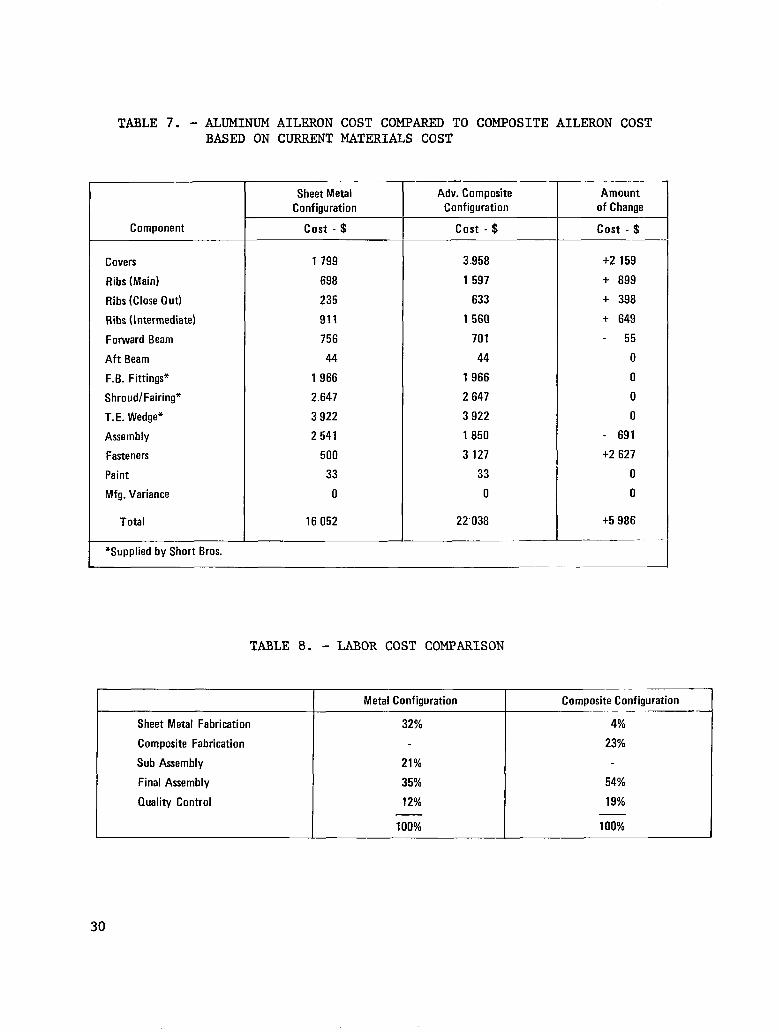
TABLE 7. - ALUMINUM AILERON COST COMPARED TO COMPOSITE AILERON COST BASED ON CURRENT MATERIALS COST
Component
Covers 1 799
Ribs (Main) 698
Ribs (Close Out) 235
Ribs (Intermediate) 911
Forward Beam 756
Aft Beam 44
F.B. Fittings* 1 966
Shroud/Fairing* 2 647
T.E. Wedge* 3 922
Assembly 2 541
Fasteners 500
Paint 33
Mfg. Variance 0
Total 16 052
*Supplied by Short Bros.
Sheet Metal Configuration
cost - $
- Adv. Composite
Configuration
cost - $
Amount of Change
cost - $
3.958 +2 159
1 597 + 899
633 + 398
1 560 + 649
701 - 55
44 0
1 966 0
2 647 0
3 922 0
1 850 - 691
3 127 +2 627
33 0
0 0
22’038 +5.986
TABLE 8. - LABOR COST COMPARISON
Sheet Metal Fabrication
Composite Fabrication
Sub Assembly
Final Assembly
Quality Control
Metal Configuration
32%
21%
35%
12%
100%
Composite Configuration
4%
23%
54%
19%
100%
30
2500
2000
z
z
is 1000
3 G 500 E E
200
LEGEND:
2187 HRS CUM AVG ATOTAL LAB01
2 GTA UNITS Cl ASSY. LABOR
1439 HRS CUM AVG
859 HRS CUM AVG 2 GTA UNITS
873 HRS CUM AVG PROJECTED AT 1DOTH UNIT
566 HRS CUM AVG 10 PROD UNITS
343 HRS CUM AVG PROJECTED AT 1OOTH UNIT
1 2 5 10 20 50 100 200
UNITS
Figure 19. - Actual learning curve development.
Projected Production Cost
The projected cost of the composite aileron was calculated based on the accumulated cost data. For this analysis it was assumed that the aileron would be one of many composite structures being fabricated. The following assumptions were made:
l Buy preplied materials and eliminate many manhours of hand layup time.
l Buy materials in sufficient quantities to reduce the cost to $86/kg ($39/lb).
l Automate the cutting methods to reduce the averaged manhours during fabrication by 30 percent.
l Standardize and procure the mechanical fasteners in larger quantities.
l Automate the assembly operations to reduced manhours during assembly by 30 percent.
31
A comparison of the projected cost of the composite aileron and the metal aileron is shown in table 9. This comparison assumes both the metal and composite ailerons are at the same point on the learning curve.
TABLE 9. - PROJECTED COST COMPARISON
Component
Sheet Metal Configuration
cost - $
Covers 1 799
Ribs (Main) 698
Ribs (Close Out) 235
Ribs (Intermediate) 911
Forward Beam 756
Aft Beam 44
F.B. Fittings 1 966
Shroud/Fairing 2 647
T. E. Wedge 3 922
Assembly 2 541
Fasteners 500
Paint 33
Mfg. Variance 0
Total 16 052
Adv. Composite Configuration
cost - $
Amount of Change
cost - $
2 378 -I- 579
985 + 287
212 - 23
463 - 448
427 - 329
44 0
1966 0
2 647 0
3 922 0
1 276 - 1 265
1 866 +l 366
33 0
0 0
16 219 + 167
CONCLUSIONS
Results obtained in this program indicate that significant improvements in structural efficiency can be achieved by the utilization of advanced com- posites for construction of aircraft secondary structures. Careful evalu- ation of alternate designs and materials for the L-1011 advanced composite inboard aileron has led to the selection of several unique material com- binations and easily manufactured structural configurations.
The advanced composite aileron is a direct replacement for the metal aileron with a weight savings of 23 percent. Due to the configurational simplicity of the components within the composite aileron, and because it contains 50 percent fewer parts and fasteners than the metal aileron, it is predicted that the composite aileron will be cost competitive with the metal aileron in a production environment.
32
Structural analysis of the composite aileron, in conjunction with the design data, concept verification, and ground tests, 'indicates that the composite aileron design meets or exceeds structural requirements.
The simple and practical manufacturing techniques developed for the composite aileron have been verified by the production of high quality parts. Reliability of the manufacturing process was demonstrated through the production of five shipsets of ailerons. Based on the manufacturing cost information accumulated during the production of 12 ailerons it is predicted that the composite aileron can be produced at a cost competitive with the aluminum aileron.
33
. . . . . . . . .---.. ,.-. ~~...
REFERENCES
1. Griffin, C. F., Fogg, L. D., Stone, R. L., and Dunning, E. G.: Advanced Composite Aileron for L-1011 Transport Aircraft - Task I, Final. NASA CR-145370, July 1978.
2. Griffin, C. F.: Advanced Composite Aileron for L-1011 Transport Aircraft - Ground Tests and Flight Evaluation. NASA CR-165664, February 1981.
3. Griffin, C. F., Fogg, L. D., Dunning, E. G.: Advanced Composite Aileron for L-1011 Transport Aircraft - Design and Analysis. NASA CR-165635, April 1981.
4. Dunning, E. G., Cobbs, W. L., Legg, R. L.: Advanced Composite Aileron for L-1011 Transport Aircraft - Aileron Manufacture. NASA CR-165718, June 1981.
34
1. Report No. 2. Government Accession No.
NASA CR-3517 -.-. _--. -:
4. Title and Subtitle
DEVELOPMENT OF AN ADVANCED COMPOSITE AILERON FOR THE L-101 1 TRANSPORT AIRCRAFT
7. Author(s)
C. F. GRlFFlN”AND E. G. DUNNING**
9. Performing Organization Name and Address
LOCKHEED-CALIFORNIA COMPANY ** ;‘;;;;R2F;zRATloN P. 0. BOX 551 BURBANK, CALIFORNIA 91520
AND N’ASHVI LLE, TENNESSEE 37202
2. Sponsoring Agency Name and Address
NATIONAL AERONAUTICS AND SPACE ADMINISTRATION WASHINGTON, DC 20546
.- .- 3. Recipient’s Catalog No.
6. Performing Organization Code
76-23 6. Performing Oqanization Report No.
LR 29911 10. Wcwk Unit No.
11. Contract or Grant No.
NAS l-15069
5. Supplementary Notes
14. Sponsoring Agency Code
LANGLEY TECHNICAL MONITOR: HERBERT A. LEYBOLD FINAL REPORT
j. Abstract
Results obtained in this program indicate that significant improvements in structural efficiency can be achieved by the utilization of advanced composites for construction of aircraft secondary structures. Careful evaluation of alternate designs and materials for the L-101 1 advanced composite inboard ailerqn has led to the selection of several unique material combinations and easily manufactured structural configurations.
The advanced composite aileron is a direct replacement for the metal aileron with a weight savings of 23 percent. Due to the configurational simplicity of the components within the composite aileron, and because it contains 50 percent fewer parts and fasteners than the metal aileron, it js predicted that the composite aileron will be cost competitive with the metal aileron in a production environment.
Structural analysis of the composite aileron, in conjunction with the design data, concept verification, and ground tests, indicates that the composite aileron design meets or exceeds structural requirements.
The simple and practical manufacturing techniques developed for the composite aileron have been verified by the production of high quality parts. Reliability of the manufacturing process was demonstrated through the production of five shipsets of ailerons. Based on the manufacturing cost information accumulated during the production of 12 ailerons it is predicted that the composite aileron can be produced at a cost competitive with the aluminum aileron.
1. Key Words lSuggested by Author(s)) 16. Distribution Statement
COMPOSITES, MATERIALS, AILERON SECONDARY STRUCTURE DESIGN, TRANSPORT AIRCRAFT, GRAPHITE/EPOXY
FEDD DISTRIBUTION
1. Security Classif. (of this report)
UNCLASSIFIED
1 20. Security Classif. (of this pe@
UNCLASSIFIED
21. No. of Pages
41 22. Rice
Subject Category 24
Available: NASA's Industrial Applications Centers NASA-Lang1 ey I 1962