Embed Size (px)
Citation preview
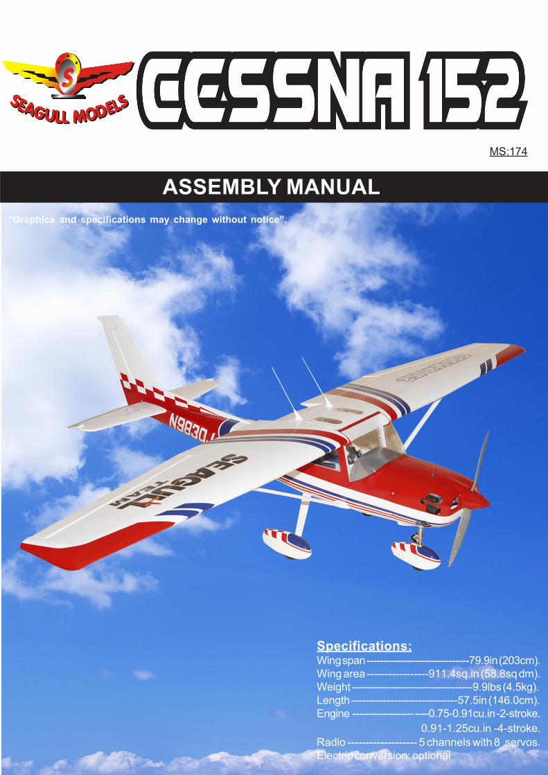
“Graphics and specifications may change without notice”.
MS:174
ASSEMBLY MANUAL
Specifications:Wing span ------------------------------79.9in (203cm).Wing area -----------------911.4sq.in (58.8sq dm).Weight ----------------------------------9.9lbs (4.5kg).Length ------------------------------57.5in (146.0cm).Engine ------------------ ----0.75-0.91cu.in -2-stroke. 0.91-1.25cu.in -4-stroke.Radio ------------------- 5 channels with 8 servos.Electric conversion: optional
CESSNA 152 Instruction Manual.
2
INTRODUCTION.
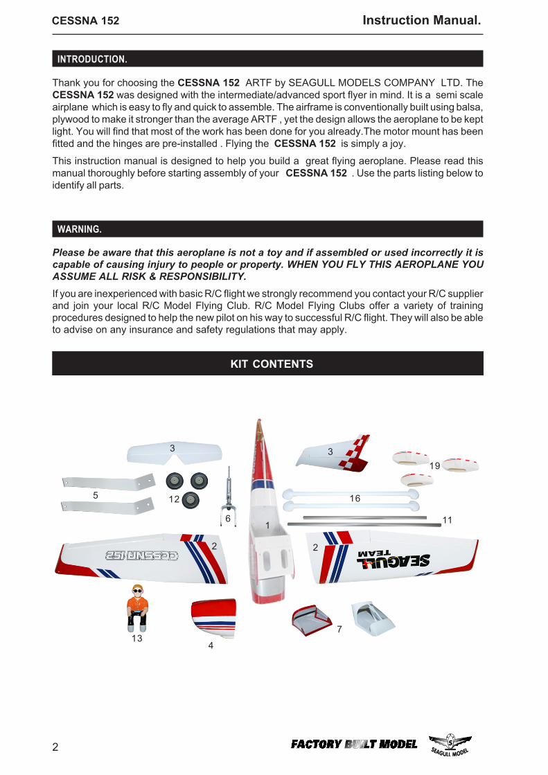
Thank you for choosing the CESSNA 152 ARTF by SEAGULL MODELS COMPANY LTD. TheCESSNA 152 was designed with the intermediate/advanced sport flyer in mind. It is a semi scaleairplane which is easy to fly and quick to assemble. The airframe is conventionally built using balsa,plywood to make it stronger than the average ARTF , yet the design allows the aeroplane to be keptlight. You will find that most of the work has been done for you already.The motor mount has beenfitted and the hinges are pre-installed . Flying the CESSNA 152 is simply a joy.
This instruction manual is designed to help you build a great flying aeroplane. Please read thismanual thoroughly before starting assembly of your CESSNA 152 . Use the parts listing below toidentify all parts.
WARNING.
Please be aware that this aeroplane is not a toy and if assembled or used incorrectly it iscapable of causing injury to people or property. WHEN YOU FLY THIS AEROPLANE YOUASSUME ALL RISK & RESPONSIBILITY.If you are inexperienced with basic R/C flight we strongly recommend you contact your R/C supplierand join your local R/C Model Flying Club. R/C Model Flying Clubs offer a variety of trainingprocedures designed to help the new pilot on his way to successful R/C flight. They will also be ableto advise on any insurance and safety regulations that may apply.
1
2 2
33
4
5
6
7
11
12
13
16
19
KIT CONTENTS
3
www.seagullmodels.com
ADDITIONAL ITEMS REQUIRED.
0.75-0.91 2-stroke. 0.91-125 4-stroke.
Computer radio with 8 servos.Glow plug to suit engine.Propeller to suit engine.Protective foam rubber for radiosystem.
TOOLS & SUPPLIES NEEDED.
Thick cyanoacrylate glue.30 minute epoxy.5 minute epoxy.Hand or electric drill.Assorted drill bits.Modelling knife.Straight edge ruler.2mm ball driver.Phillips head screwdriver.220 grit sandpaper.90° square or builder’s triangle.Wire cutters.Masking tape & T-pins.Thread-lock.Paper towels.
SEA17401 FuselageSEA17402 Wing SetSEA17403 Tail SetSEA17404 CowlingSEA17405 Main Landing GearSEA17406 Nose Landing GearSEA17407 CanopySEA17408 DecalSEA17409 Pushrod SetSEA17410 Hardware SetSEA17411 Wing Tube SetSEA17412 WheelsSEA17413 PilotSEA17214 Engine Mount SetSEA17415 Fuel TankSEA17416 Strut Wing SetSEA17417 WindscreenSEA17418 SpinnerSEA17419 Fiberglass Wheel PantsSEA17420 EP Mount Set
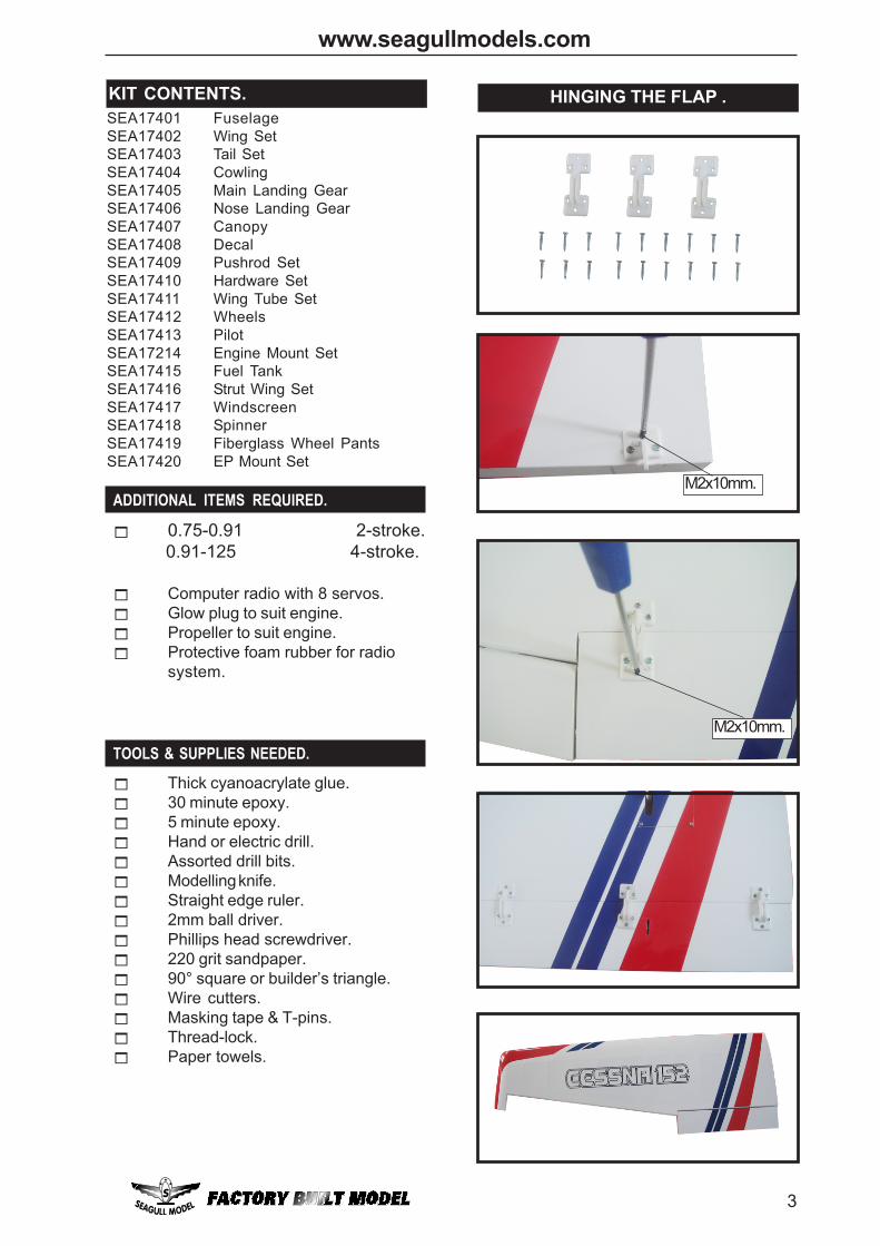
KIT CONTENTS.S HINGING THE FLAP .
M2x10mm.
M2x10mm.
CESSNA 152 Instruction Manual.
4
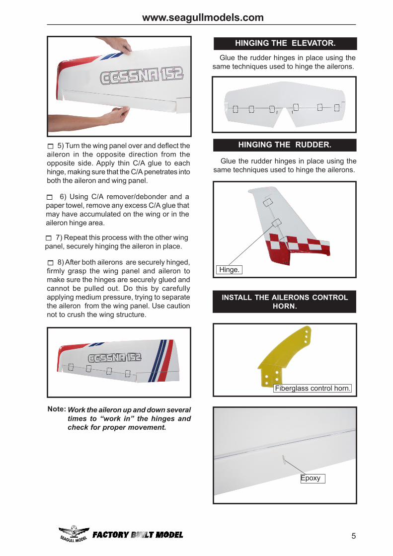
4) Deflect the aileron and completelysaturate each hinge with thin C/A glue. Theailerons front surface should lightly contact thewing during this procedure. Ideally, when thehinges are glued in place, a 1/64” gap or lesswill be maintained throughout the lengh of theaileron to the wing panel hinge line.
The hinge is constructed of a specialmaterial that allows the C/A to wickor penetrate and distributethroughout the hinge, securelybonding it to the wood structure ofthe wing panel and aileron.
Note:
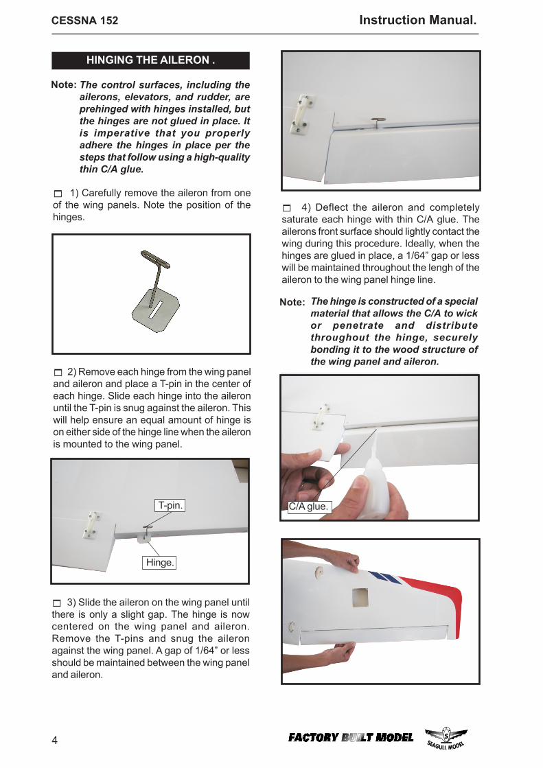
The control surfaces, including theailerons, elevators, and rudder, areprehinged with hinges installed, butthe hinges are not glued in place. Itis imperative that you properlyadhere the hinges in place per thesteps that follow using a high-qualitythin C/A glue.
2) Remove each hinge from the wing paneland aileron and place a T-pin in the center ofeach hinge. Slide each hinge into the aileronuntil the T-pin is snug against the aileron. Thiswill help ensure an equal amount of hinge ison either side of the hinge line when the aileronis mounted to the wing panel.
Note:
1) Carefully remove the aileron from oneof the wing panels. Note the position of thehinges.
3) Slide the aileron on the wing panel untilthere is only a slight gap. The hinge is nowcentered on the wing panel and aileron.Remove the T-pins and snug the aileronagainst the wing panel. A gap of 1/64” or lessshould be maintained between the wing paneland aileron.
HINGING THE AILERON .
Hinge.
T-pin. C/A glue.
5
www.seagullmodels.com
8) After both ailerons are securely hinged,firmly grasp the wing panel and aileron tomake sure the hinges are securely glued andcannot be pulled out. Do this by carefullyapplying medium pressure, trying to separatethe aileron from the wing panel. Use cautionnot to crush the wing structure.
7) Repeat this process with the other wingpanel, securely hinging the aileron in place.
6) Using C/A remover/debonder and apaper towel, remove any excess C/A glue thatmay have accumulated on the wing or in theaileron hinge area.
Work the aileron up and down severaltimes to “work in” the hinges andcheck for proper movement.
Note:
5) Turn the wing panel over and deflect theaileron in the opposite direction from theopposite side. Apply thin C/A glue to eachhinge, making sure that the C/A penetrates intoboth the aileron and wing panel.
HINGING THE ELEVATOR.
Glue the rudder hinges in place using thesame techniques used to hinge the ailerons.
HINGING THE RUDDER.
Glue the rudder hinges in place using thesame techniques used to hinge the ailerons.
Hinge.
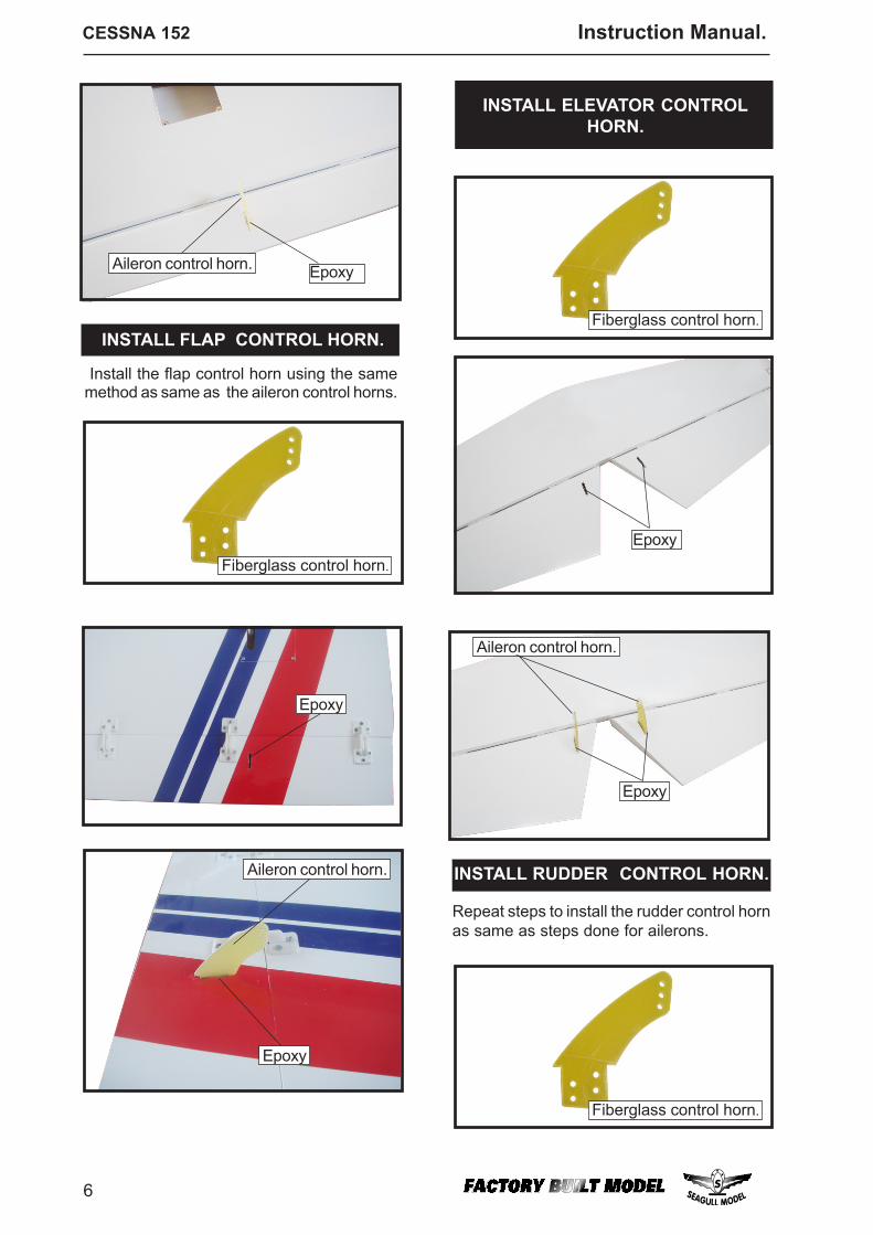
INSTALL THE AILERONS CONTROLHORN.
Epoxy
Fiberglass control horn.
CESSNA 152 Instruction Manual.
6
INSTALL ELEVATOR CONTROLHORN.
Epoxy
Aileron control horn.
Epoxy
Aileron control horn. INSTALL RUDDER CONTROL HORN.
Repeat steps to install the rudder control hornas same as steps done for ailerons.
Aileron control horn. Epoxy
Install the flap control horn using the samemethod as same as the aileron control horns.
INSTALL FLAP CONTROL HORN.
Fiberglass control horn.
Fiberglass control horn.
Fiberglass control horn.
Epoxy
Epoxy
7
www.seagullmodels.com
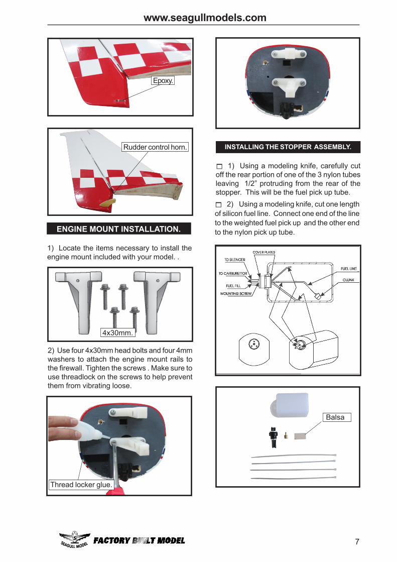
Epoxy.
Rudder control horn.
Thread locker glue.
ENGINE MOUNT INSTALLATION.
1) Locate the items necessary to install theengine mount included with your model. .
2) Use four 4x30mm head bolts and four 4mmwashers to attach the engine mount rails tothe firewall. Tighten the screws . Make sure touse threadlock on the screws to help preventthem from vibrating loose.
4x30mm.
INSTALLING THE STOPPER ASSEMBLY.
2) Using a modeling knife, cut one lengthof silicon fuel line. Connect one end of the lineto the weighted fuel pick up and the other endto the nylon pick up tube.
1) Using a modeling knife, carefully cutoff the rear portion of one of the 3 nylon tubesleaving 1/2” protruding from the rear of thestopper. This will be the fuel pick up tube.
Balsa
CESSNA 152 Instruction Manual.
8
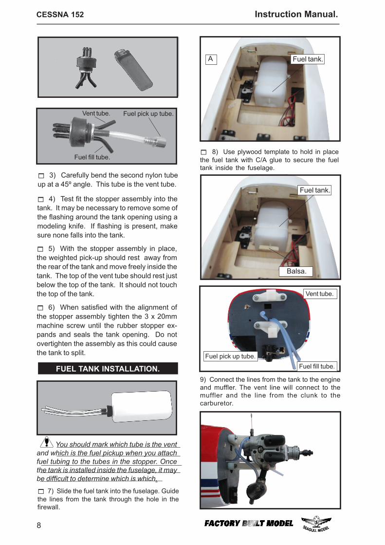
9) Connect the lines from the tank to the engineand muffler. The vent line will connect to themuffler and the line from the clunk to thecarburetor.
Fuel tank.
Vent tube.
Fuel pick up tube.Fuel fill tube.
3) Carefully bend the second nylon tubeup at a 45º angle. This tube is the vent tube.
4) Test fit the stopper assembly into thetank. It may be necessary to remove some ofthe flashing around the tank opening using amodeling knife. If flashing is present, makesure none falls into the tank.
5) With the stopper assembly in place,the weighted pick-up should rest away fromthe rear of the tank and move freely inside thetank. The top of the vent tube should rest justbelow the top of the tank. It should not touchthe top of the tank.
6) When satisfied with the alignment ofthe stopper assembly tighten the 3 x 20mmmachine screw until the rubber stopper ex-pands and seals the tank opening. Do notovertighten the assembly as this could causethe tank to split.
You should mark which tube is the ventand which is the fuel pickup when you attachfuel tubing to the tubes in the stopper. Oncethe tank is installed inside the fuselage, it maybe difficult to determine which is which.
FUEL TANK INSTALLATION.
7) Slide the fuel tank into the fuselage. Guidethe lines from the tank through the hole in thefirewall.
Fuel tank.
8) Use plywood template to hold in placethe fuel tank with C/A glue to secure the fueltank inside the fuselage.
A
Vent tube. Fuel pick up tube.
Fuel fill tube.
Balsa.
9
www.seagullmodels.com
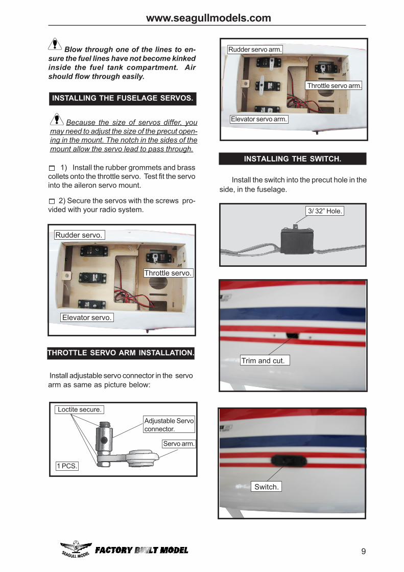
Blow through one of the lines to en-sure the fuel lines have not become kinkedinside the fuel tank compartment. Airshould flow through easily.
INSTALLING THE FUSELAGE SERVOS.
Throttle servo.
Elevator servo.
Rudder servo.
THROTTLE SERVO ARM INSTALLATION.
Install adjustable servo connector in the servoarm as same as picture below:
Adjustable Servoconnector.
Servo arm.
Loctite secure.
1 PCS.
Throttle servo arm.
Elevator servo arm.
Rudder servo arm.
1) Install the rubber grommets and brasscollets onto the throttle servo. Test fit the servointo the aileron servo mount.
2) Secure the servos with the screws pro-vided with your radio system.
Because the size of servos differ, youmay need to adjust the size of the precut open-ing in the mount. The notch in the sides of themount allow the servo lead to pass through.
INSTALLING THE SWITCH.
3/ 32” Hole.
Install the switch into the precut hole in theside, in the fuselage.
Trim and cut.
Switch.
CESSNA 152 Instruction Manual.
10
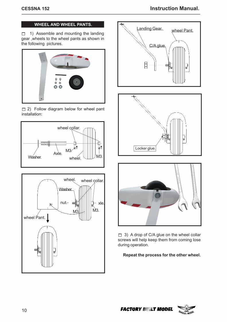
2) Follow diagram below for wheel pantinstallation:
1) Assemble and mounting the landinggear ,wheels to the wheel pants as shown inthe following pictures.
WHEEL AND WHEEL PANTS.
wheel collar.
wheel.Axle.
Washer.M3.
M3.
C/A glue.
Landing Gear. wheel Pant.
Axle.
Locker glue.
3) A drop of C/A glue on the wheel collarscrews will help keep them from coming loseduring operation.
Repeat the process for the other wheel.
wheel Pant.
wheel.
M3.M3.
wheel collar.
nut.
Washer.
11
www.seagullmodels.com
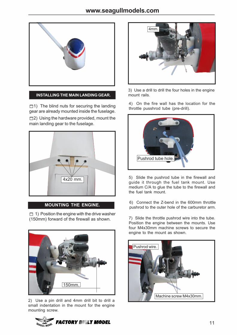
1) The blind nuts for securing the landinggear are already mounted inside the fuselage.
2) Using the hardware provided, mount themain landing gear to the fuselage.
INSTALLING THE MAIN LANDING GEAR.
4x20 mm.
150mm.
MOUNTING THE ENGINE.
1) Position the engine with the drive washer(150mm) forward of the firewall as shown.
2) Use a pin drill and 4mm drill bit to drill asmall indentation in the mount for the enginemounting screw.
4mm.
5) Slide the pushrod tube in the firewall andguide it through the fuel tank mount. Usemedium C/A to glue the tube to the firewall andthe fuel tank mount.
Pushrod tube hole.
3) Use a drill to drill the four holes in the enginemount rails.
4) On the fire wall has the location for thethrottle pusshrod tube (pre-drill).
6) Connect the Z-bend in the 600mm throttlepushrod to the outer hole of the carburetor arm.
7) Slide the throttle pushrod wire into the tube.Position the engine between the mounts. Usefour M4x30mm machine screws to secure theengine to the mount as shown.
Machine screw M4x30mm.
Pushrod wire.
CESSNA 152 Instruction Manual.
12
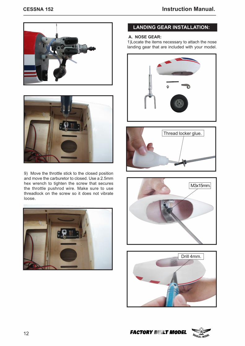
LANDING GEAR INSTALLATION:
A. NOSE GEAR:
9) Move the throttle stick to the closed positionand move the carburetor to closed. Use a 2.5mmhex wrench to tighten the screw that securesthe throttle pushrod wire. Make sure to usethreadlock on the screw so it does not vibrateloose.
1)Locate the items necessary to attach the noselanding gear that are included with your model.
Thread locker glue.
M3x15mm.
Drill 4mm.
13
www.seagullmodels.com
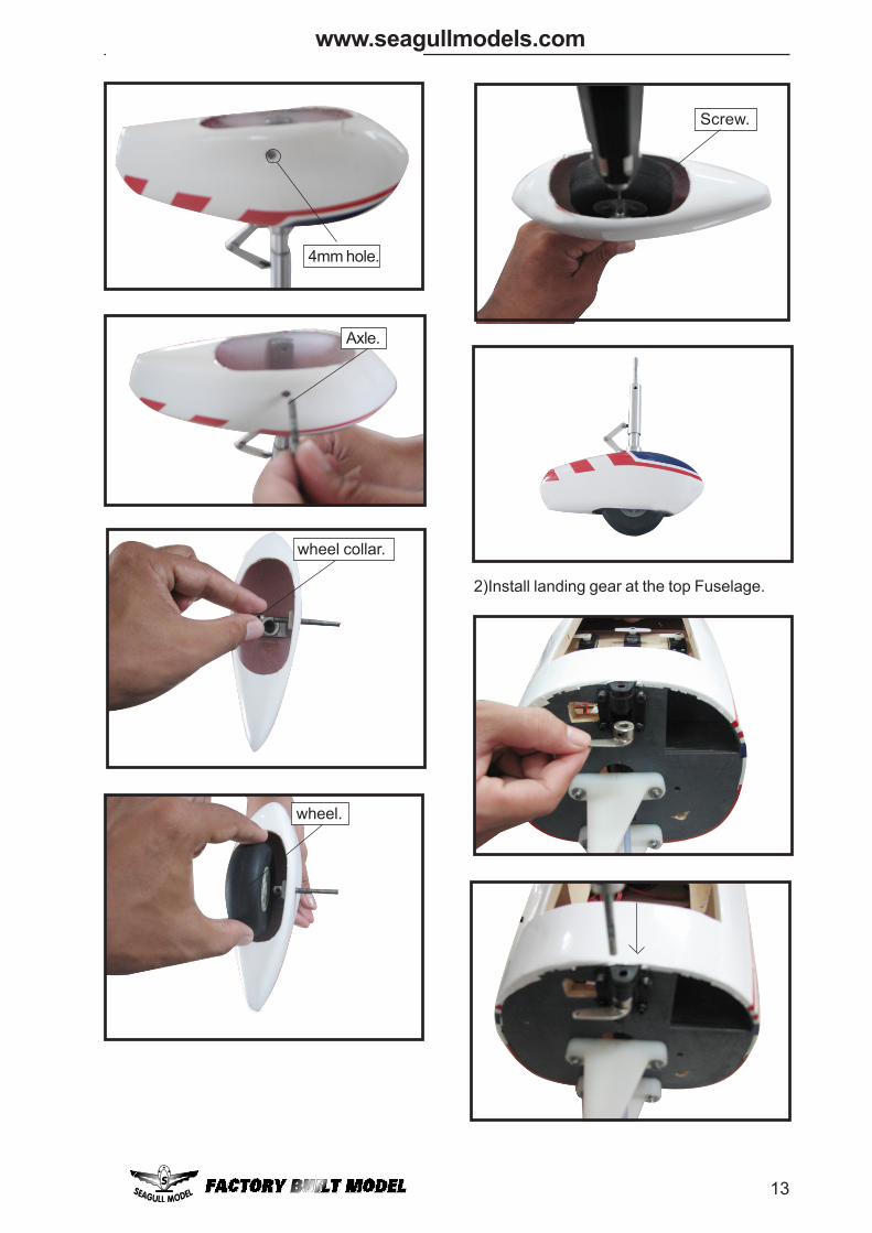
2)Install landing gear at the top Fuselage.
4mm hole.
Axle.
wheel collar.
wheel.
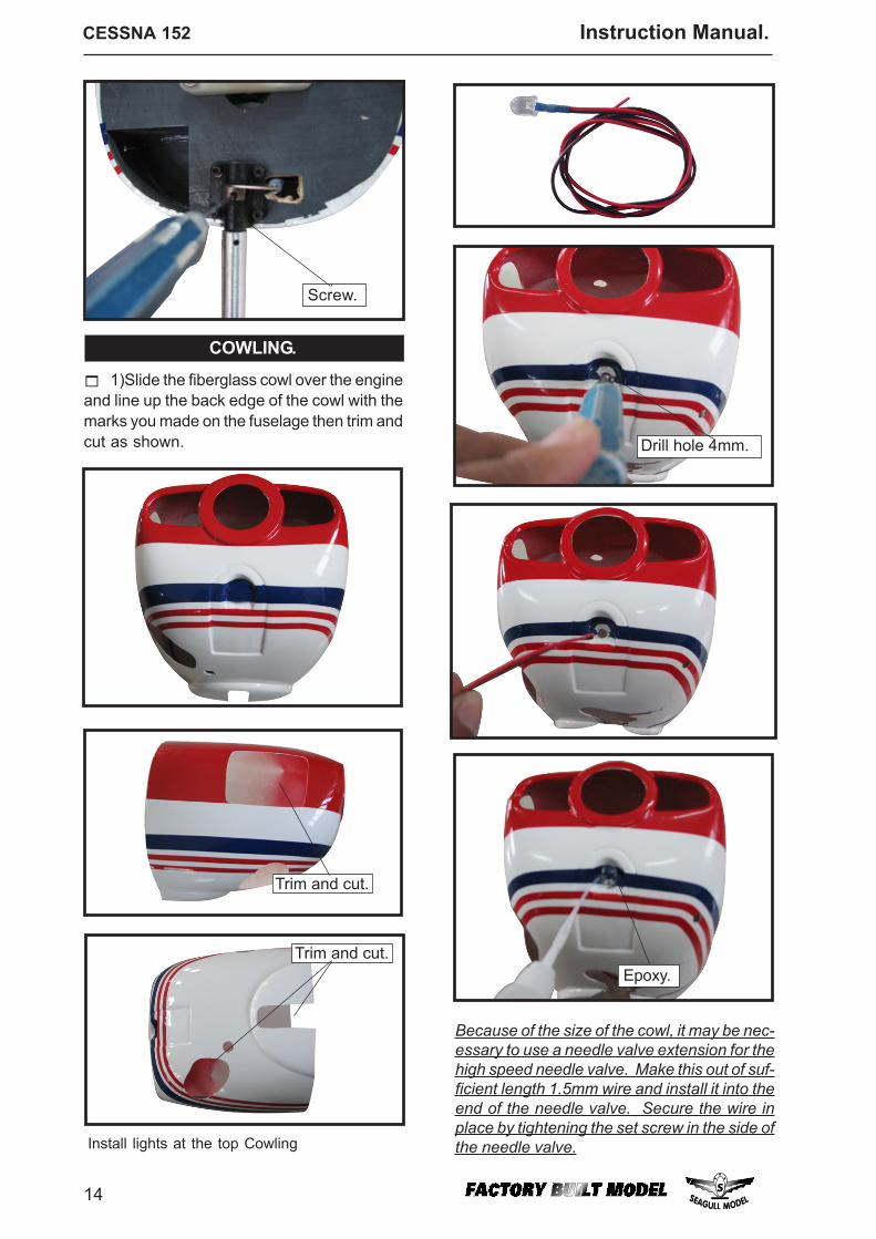
Screw.
CESSNA 152 Instruction Manual.
14
COWLING.
Trim and cut.
1)Slide the fiberglass cowl over the engineand line up the back edge of the cowl with themarks you made on the fuselage then trim andcut as shown.
Trim and cut.
Because of the size of the cowl, it may be nec-essary to use a needle valve extension for thehigh speed needle valve. Make this out of suf-ficient length 1.5mm wire and install it into theend of the needle valve. Secure the wire inplace by tightening the set screw in the side ofthe needle valve.Install lights at the top Cowling
Screw.
Epoxy.
Drill hole 4mm.
15
www.seagullmodels.com
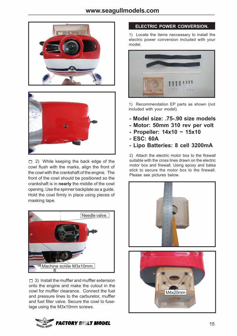
2) Attach the electric motor box to the firewallsuitable with the cross lines drawn on the electricmotor box and firewall. Using epoxy and balsastick to secure the motor box to the firewall.Please see pictures below.
M4x20mm
3) Install the muffler and muffler extensiononto the engine and make the cutout in thecowl for muffler clearance. Connect the fueland pressure lines to the carburetor, mufflerand fuel filler valve. Secure the cowl to fuse-lage using the M3x10mm screws.
ELECTRIC POWER CONVERSION.
1) Locate the items neccessary to install theelectric power conversion included with yourmodel.
Machine screw M3x10mm.
Needle valve.
1) Recommendation EP parts as shown (notincluded with your model).
2) While keeping the back edge of thecowl flush with the marks, align the front ofthe cowl with the crankshaft of the engine. Thefront of the cowl should be positioned so thecrankshaft is in nearly the middle of the cowlopening. Use the spinner backplate as a guide.Hold the cowl firmly in place using pieces ofmasking tape.
- Model size: .75-.90 size models- Motor: 50mm 310 rev per volt- Propeller: 14x10 ~ 15x10- ESC: 60A- Lipo Batteries: 8 cell 3200mA
CESSNA 152 Instruction Manual.
16
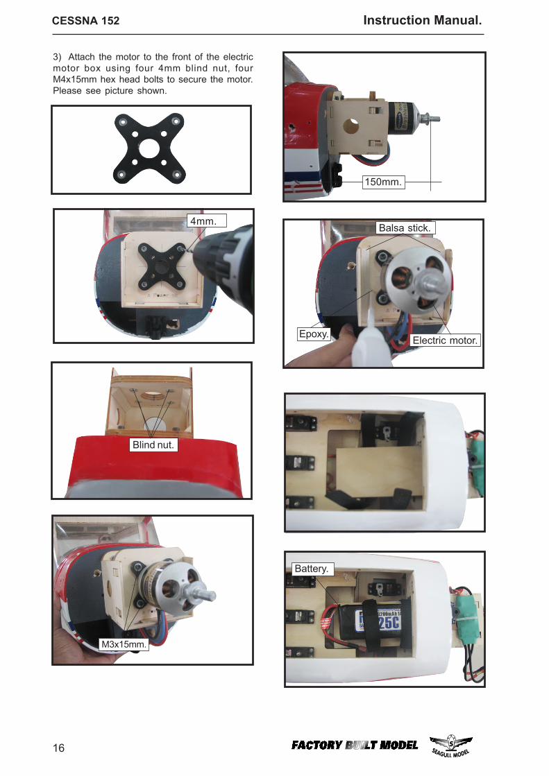
Balsa stick.
Electric motor.Epoxy.
M3x15mm.
150mm.
Battery.
3) Attach the motor to the front of the electricmotor box using four 4mm blind nut, fourM4x15mm hex head bolts to secure the motor.Please see picture shown.
4mm.
Blind nut.
17
www.seagullmodels.com
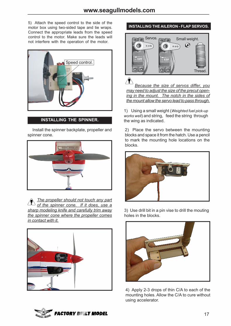
5) Attach the speed control to the side of themotor box using two-sided tape and tie wraps.Connect the appropriate leads from the speedcontrol to the motor. Make sure the leads willnot interfere with the operation of the motor.
Speed control.
INSTALLING THE SPINNER.
Install the spinner backplate, propeller andspinner cone.
The propeller should not touch any partof the spinner cone. If it does, use a
sharp modeling knife and carefully trim awaythe spinner cone where the propeller comesin contact with it.
INSTALLING THE AILERON - FLAP SERVOS.
Servos. Small weight.
Thread.
Because the size of servos differ, youmay need to adjust the size of the precut open-ing in the mount. The notch in the sides ofthe mount allow the servo lead to pass through.
1) Using a small weight (Weighted fuel pick-upworks well) and string, feed the string throughthe wing as indicated.
3) Use drill bit in a pin vise to drill the moutingholes in the blocks.
2) Place the servo between the mountingblocks and space it from the hatch. Use a pencilto mark the mounting hole locations on theblocks.
4) Apply 2-3 drops of thin C/A to each of themounting holes. Allow the C/A to cure withoutusing accelerator.
CESSNA 152 Instruction Manual.
18
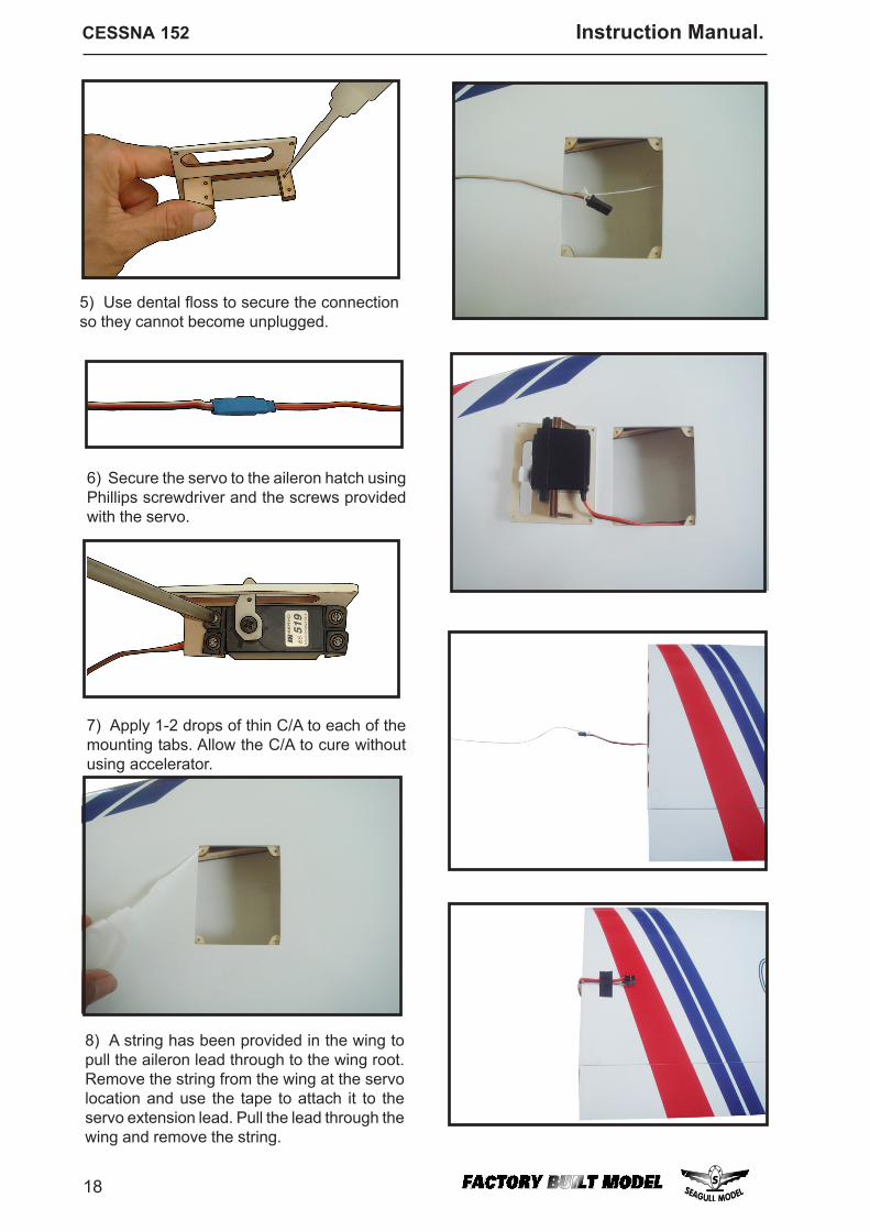
8) A string has been provided in the wing topull the aileron lead through to the wing root.Remove the string from the wing at the servolocation and use the tape to attach it to theservo extension lead. Pull the lead through thewing and remove the string.
6) Secure the servo to the aileron hatch usingPhillips screwdriver and the screws providedwith the servo.
7) Apply 1-2 drops of thin C/A to each of themounting tabs. Allow the C/A to cure withoutusing accelerator.
5) Use dental floss to secure the connectionso they cannot become unplugged.

19
www.seagullmodels.com
9) Set the aileron hatch in place and use aPhillips screw driver to install it with four woodscrews.
AILERON PUSHROD HORN INSTALLATION
M3 lock nut.M3 clevis.
100mm.
Wing.
Aileron.
M2 lock nut.
INSTALLING THE FLAP SERVO
Repeat the procedure for the aileron servo.
INSTALLING THE HORIZONTAL STABILIZER.
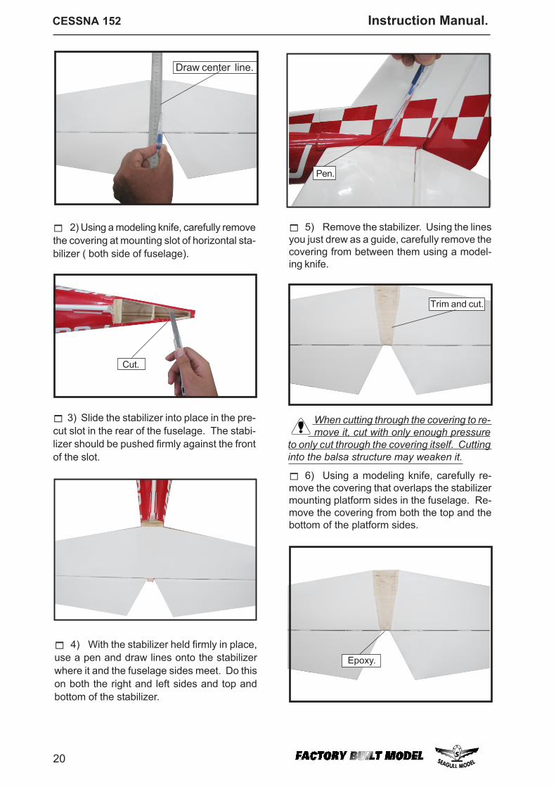
1) Using a ruler and a pen, locate thecenterline of the horizontal stabilizer, at the trail-ing edge, and place a mark. Use a triangleand extend this mark, from back to front,across the top of the stabilizer. Also extendthis mark down the back of the trailing edge ofthe stabilizer.
Wing.
Flap.
M2 lock nut.
M3 lock nut.M3 clevis.
90mm.
CESSNA 152 Instruction Manual.
20
2) Using a modeling knife, carefully removethe covering at mounting slot of horizontal sta-bilizer ( both side of fuselage).
Pen.
Trim and cut.
5) Remove the stabilizer. Using the linesyou just drew as a guide, carefully remove thecovering from between them using a model-ing knife.
Cut.
3) Slide the stabilizer into place in the pre-cut slot in the rear of the fuselage. The stabi-lizer should be pushed firmly against the frontof the slot.
4) With the stabilizer held firmly in place,use a pen and draw lines onto the stabilizerwhere it and the fuselage sides meet. Do thison both the right and left sides and top andbottom of the stabilizer.
When cutting through the covering to re-move it, cut with only enough pressure
to only cut through the covering itself. Cuttinginto the balsa structure may weaken it.
Epoxy.
6) Using a modeling knife, carefully re-move the covering that overlaps the stabilizermounting platform sides in the fuselage. Re-move the covering from both the top and thebottom of the platform sides.
Draw center line.
21
www.seagullmodels.com
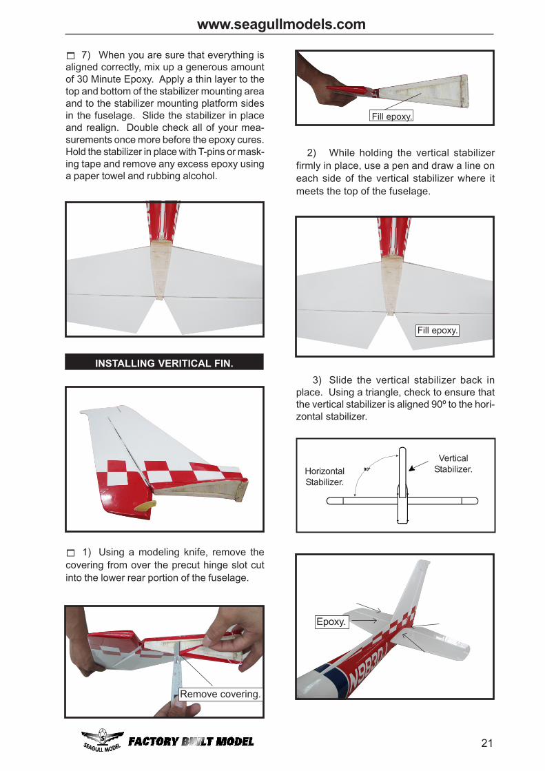
INSTALLING VERITICAL FIN.
1) Using a modeling knife, remove thecovering from over the precut hinge slot cutinto the lower rear portion of the fuselage.
Remove covering.
2) While holding the vertical stabilizerfirmly in place, use a pen and draw a line oneach side of the vertical stabilizer where itmeets the top of the fuselage.
Fill epoxy.
Epoxy.
90º
VerticalStabilizer.Horizontal
Stabilizer.
3) Slide the vertical stabilizer back inplace. Using a triangle, check to ensure thatthe vertical stabilizer is aligned 90º to the hori-zontal stabilizer.
7) When you are sure that everything isaligned correctly, mix up a generous amountof 30 Minute Epoxy. Apply a thin layer to thetop and bottom of the stabilizer mounting areaand to the stabilizer mounting platform sidesin the fuselage. Slide the stabilizer in placeand realign. Double check all of your mea-surements once more before the epoxy cures.Hold the stabilizer in place with T-pins or mask-ing tape and remove any excess epoxy usinga paper towel and rubbing alcohol.
Fill epoxy.
CESSNA 152 Instruction Manual.
22
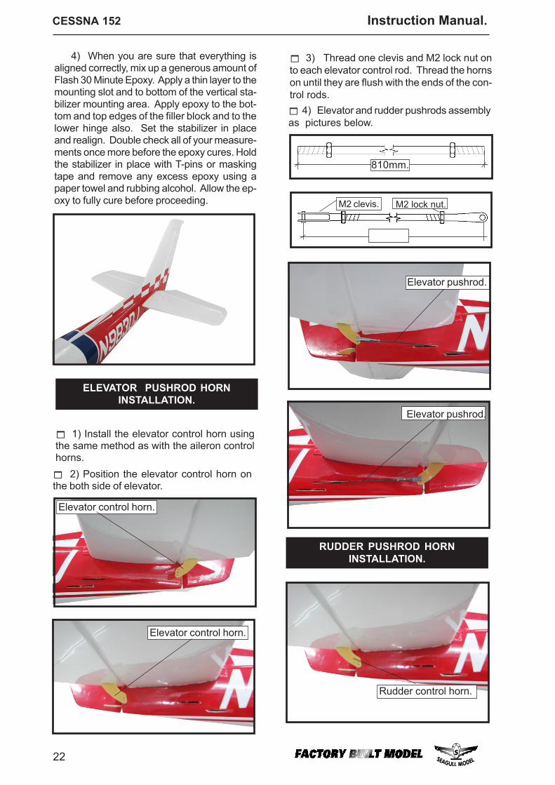
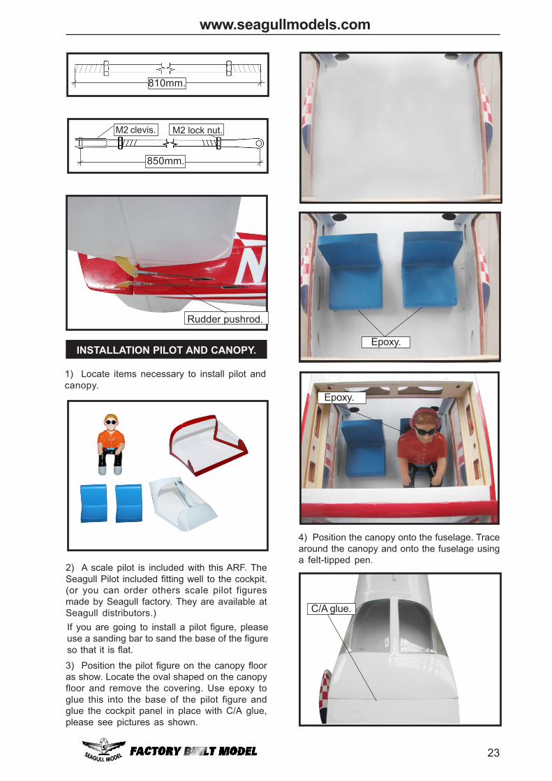
RUDDER PUSHROD HORNINSTALLATION.
Rudder control horn.
ELEVATOR PUSHROD HORNINSTALLATION.
Elevator control horn.
1) Install the elevator control horn usingthe same method as with the aileron controlhorns. 2) Position the elevator control horn on
the both side of elevator.
4) Elevator and rudder pushrods assemblyas pictures below.
3) Thread one clevis and M2 lock nut onto each elevator control rod. Thread the hornson until they are flush with the ends of the con-trol rods.
Elevator pushrod.
M2 lock nut.M2 clevis.
810mm.
Elevator control horn.
Elevator pushrod.
4) When you are sure that everything isaligned correctly, mix up a generous amount ofFlash 30 Minute Epoxy. Apply a thin layer to themounting slot and to bottom of the vertical sta-bilizer mounting area. Apply epoxy to the bot-tom and top edges of the filler block and to thelower hinge also. Set the stabilizer in placeand realign. Double check all of your measure-ments once more before the epoxy cures. Holdthe stabilizer in place with T-pins or maskingtape and remove any excess epoxy using apaper towel and rubbing alcohol. Allow the ep-oxy to fully cure before proceeding.
23
www.seagullmodels.com
Rudder pushrod.
M2 lock nut.M2 clevis.
810mm.
850mm.
3) Position the pilot figure on the canopy flooras show. Locate the oval shaped on the canopyfloor and remove the covering. Use epoxy toglue this into the base of the pilot figure andglue the cockpit panel in place with C/A glue,please see pictures as shown.
If you are going to install a pilot figure, pleaseuse a sanding bar to sand the base of the figureso that it is flat.
INSTALLATION PILOT AND CANOPY.
1) Locate items necessary to install pilot andcanopy.
2) A scale pilot is included with this ARF. TheSeagull Pilot included fitting well to the cockpit.(or you can order others scale pilot figuresmade by Seagull factory. They are available atSeagull distributors.)
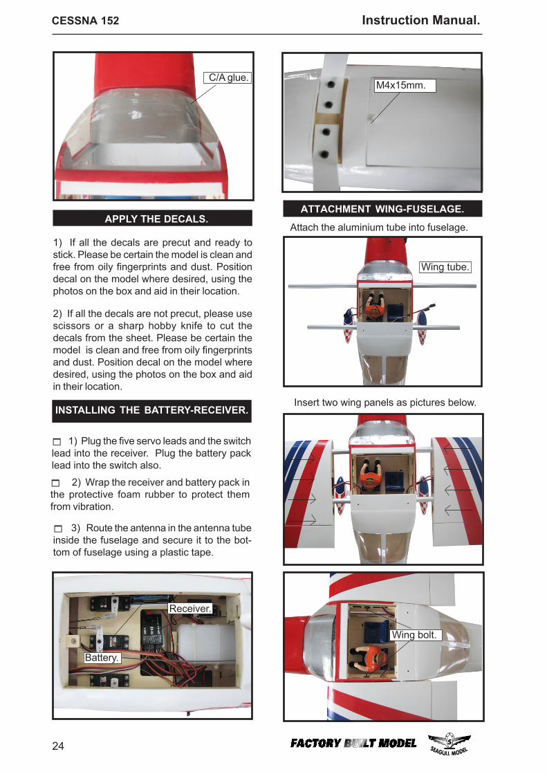
4) Position the canopy onto the fuselage. Tracearound the canopy and onto the fuselage usinga felt-tipped pen.
Epoxy.
Epoxy.
C/A glue.
CESSNA 152 Instruction Manual.
24
Wing bolt.
INSTALLING THE BATTERY-RECEIVER.
1) Plug the five servo leads and the switchlead into the receiver. Plug the battery packlead into the switch also.
3) Route the antenna in the antenna tubeinside the fuselage and secure it to the bot-tom of fuselage using a plastic tape.
2) Wrap the receiver and battery pack inthe protective foam rubber to protect themfrom vibration.
APPLY THE DECALS.
1) If all the decals are precut and ready tostick. Please be certain the model is clean andfree from oily fingerprints and dust. Positiondecal on the model where desired, using thephotos on the box and aid in their location.
2) If all the decals are not precut, please usescissors or a sharp hobby knife to cut thedecals from the sheet. Please be certain themodel is clean and free from oily fingerprintsand dust. Position decal on the model wheredesired, using the photos on the box and aidin their location.
Receiver.
Battery.
ATTACHMENT WING-FUSELAGE.
Wing tube.
Attach the aluminium tube into fuselage.
Insert two wing panels as pictures below.
M4x15mm.C/A glue.
25
www.seagullmodels.com
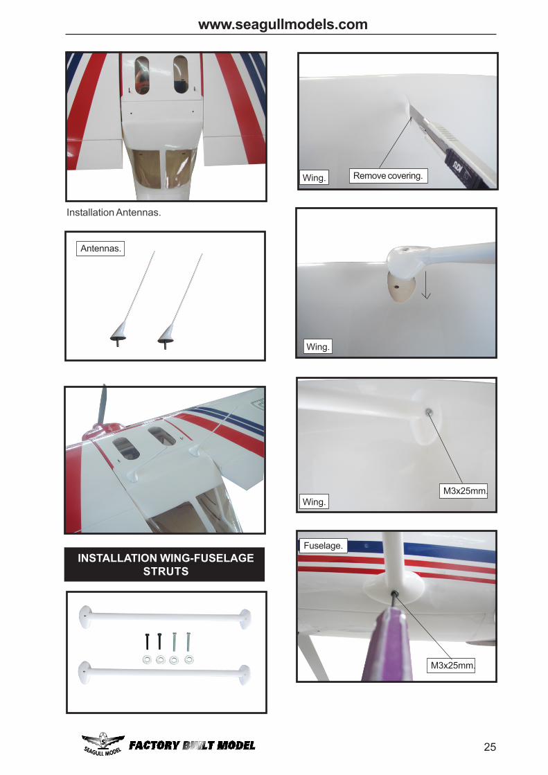
INSTALLATION WING-FUSELAGESTRUTS
Installation Antennas.
Wing.
Wing.
Wing. Remove covering.
M3x25mm.
Antennas.
Fuselage.
M3x25mm.
CESSNA 152 Instruction Manual.
26
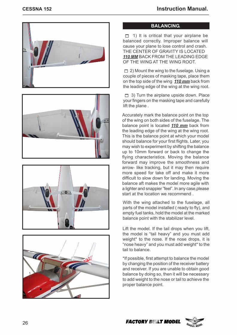
Lift the model. If the tail drops when you lift,the model is “tail heavy” and you must addweight* to the nose. If the nose drops, it is“nose heavy” and you must add weight* to thetail to balance.
*If possible, first attempt to balance the modelby changing the position of the receiver batteryand receiver. If you are unable to obtain goodbalance by doing so, then it will be necessaryto add weight to the nose or tail to achieve theproper balance point.
BALANCING.
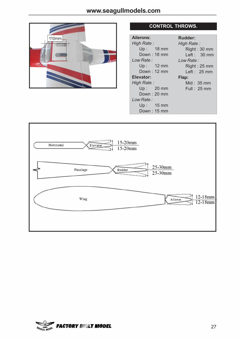
1) It is critical that your airplane bebalanced correctly. Improper balance willcause your plane to lose control and crash.THE CENTER OF GRAVITY IS LOCATED110 MM BACK FROM THE LEADING EDGEOF THE WING AT THE WING ROOT.
3) Turn the airplane upside down. Placeyour fingers on the masking tape and carefullylift the plane .
2) Mount the wing to the fuselage. Using acouple of pieces of masking tape, place themon the top side of the wing 110 mm back fromthe leading edge of the wing at the wing root.
Accurately mark the balance point on the topof the wing on both sides of the fuselage. Thebalance point is located 110 mm back fromthe leading edge of the wing at the wing root.This is the balance point at which your modelshould balance for your first flights. Later, youmay wish to experiment by shifting the balanceup to 10mm forward or back to change theflying characteristics. Moving the balanceforward may improve the smoothness andarrow- like tracking, but it may then requiremore speed for take off and make it moredifficult to slow down for landing. Moving thebalance aft makes the model more agile witha lighter and snappier ”feel”. In any case,pleasestart at the location we recommend .
With the wing attached to the fuselage, allparts of the model installed ( ready to fly), andempty fuel tanks, hold the model at the markedbalance point with the stabilizer level.
27
www.seagullmodels.com
CONTROL THROWS.
Ailerons:High Rate :
Up : 18 mmDown : 18 mm
Low Rate :Up : 12 mmDown : 12 mm
Elevator:High Rate :
Up : 20 mmDown : 20 mm
Low Rate :Up : 15 mmDown : 15 mm
Rudder:High Rate :
Right : 30 mmLeft : 30 mm
Low Rate :Right : 25 mmLeft : 25 mm
Flap:Mid : 35 mmFull : 25 mm
110mm.
CESSNA 152 Instruction Manual.
28
We wish you many safe and enjoyableflights with your CESSNA 152.
7) Check the receiver antenna. It shouldbe fully extended and not coiled up inside thefuselage.
3) Double check the balance of the air-plane. Do this with the fuel tank empty.
4) Check the control surfaces. All shouldmove in the correct direction and not bind inany way.
5) If your radio transmitter is equippedwith dual rate switches double check that theyare on the low rate setting for your first fewflights.
2) Check every bolt and every glue jointin the CESSNA 152 to ensure that everythingis tight and well bonded.
6) Check to ensure the control surfacesare moving the proper amount for both lowand high rate settings.
1) Completely charge your transmitterand receiver batteries before your first day offlying.
D) Check the throttle. Moving thethrottle stick forward should open the carbu-retor barrel. If it does not, flip the servo re-versing switch on your transmitter to changethe direction. E) From behind the airplane, look atthe aileron on the right wing half. Move theaileron stick to the right. The right aileronshould move up and the other aileron shouldmove down. If it does not, flip the servo re-versing switch on your transmitter to changethe direction.
C) Check the rudder. Looking frombehind the airplane, move the rudder stick tothe right. The rudder should move to the right.If it does not, flip the servo reversing switch onyour transmitter to change the direction.
A) Plug in your radio system per themanufacturer's instructions and turn every-thing on.
B) Check the elevator first. Pull backon the elevator stick. The elevator halvesshould move up. If it they do not, flip the servoreversing switch on your transmitter to changethe direction.
8) Properly balance the propeller. An outof balance propeller will cause excessive vi-bration which could lead to engine and/or air-frame failure.
PREFLIGHT CHECK. Check the operation and direction of theelevator, rudder, ailerons and throttle.
FLIGHT PREPARATION.