Embed Size (px)
Citation preview
DEVELOPMENT OF AERO GAS TURBINE ANNULAR COMBUSTOR : AN OVERVIEW
Dr. C. BADARINATH
Combustion group, GTRE, Bangalore-93
INTRODUCTION
An overview of current practice and procedures for design, analysis and
development of aero gas turbine combustors is presented here. The specific focus of this write up is design of an annular combustion system for an aircraft gas turbine application. However, most of the design rules will also apply to other applications. While can and annular combustor configurations are widely used in existing engines, the annular combustor is more prevalent in modern aircraft gas turbine engine designs, and an increasing number of industrial applications now use engines derived from aero gas turbines.
A gas turbine combustor is a device for raising the temperature of the incoming air stream from compressor by the addition and combustion of fuel. In serving this purpose, the combustor must satisfy many conflicting requirement. It must be capable of initiating ignition easily and must operate stably over a wide range of conditions. At all operating points, it must essentially provide for complete combustion of the fuel while minimizing the formation and emission of undesirable pollutants. To avoid damaging the turbine, sufficient mixing must be achieved in the combustor to obtain an acceptable exit gas temperature distribution. The combustor must also operate with as minimum a pressure loss as practical to maintain high overall performance. Finally, all of these functions must be performed in a configuration, which has minimum size, weight, and cost and which is sufficiently durable to achieve an acceptable operating life.
Combustor is one of the main sub-systems of the engine where the most varied and complex physical phenomena take place. Highly 3-D flows, turbulent, dysphasic, mixed flows, complex chemical reactions, unsteady and multidimensional flow of heat transfer, radiative flows are some of the problems. The fuel injection process alone using a particular type of fuel injection system called the air blast atomizer involves problems related to the shearing of air-fuel sheets, either co-rotating or counter rotating the formation of droplets, their mixing, trajectory, size and evaporation. Gas Turbine combustors cannot accept high velocities of air at the inlet. It would be almost impossible to stabilize combustion of Kerosene products in such a high velocity air stream. Furthermore the fundamental pressure loss which occurs whenever heat is added to a flowing gas is directly proportional to the square of the velocity. Therefore it is necessary to reduce the compressor exit velocity which is in the range of 90 to 180 meters per second by at least 50% before it is discharged into the combustion chamber. This is achieved through a
diffuser which accomplishes this effectively, controlling boundary layer growth and avoiding flow separation along the diffuser walls while minimizing length and overall size. The subsonic diffuser is one of the critical components of a combustor. A diffuser is used to reduce the average velocity of fluid flow in a duct. In subsonic flow, this reduction in velocity is achieved by gradually increasing the cross sectional area of the duct. For an efficient diffuser, the reduction in velocity is accompanied by an increase in static pressure. A diffuser in its simplest form may be defined by its non-dimensional length, its area ratio and the divergence angle. If the divergence angle is too small then the pressure loss will be less, but longer diffuser will produce high frictional losses and also the overall weight of the engine will be increased. On the other hand, if the divergence angle is too large, the shorter diffuser will give lower frictional losses, but flow separation in the boundary layer will produce excessive pressure loss. Dump diffuser is used in modern aero gas turbine combustors in which the flow from compressor exit passes through the pre diffuser and is dumped in the dump region. The length is quite short as compared to the long aerodynamic diffuser in which the flow is all along attached to the diffuser walls. The short dump diffusers give an advantage in gaining the thrust-to-weight (T/W) ratio of the engine. The cut-and-try methods generally used to design combustion chambers in the past have been giving way in recent years to more systematic approach based on analysis and co-relation of experimental data .This approach is potentially capable of substantially reducing development time and expense while improving combustor performance. The analytical methods and co-relations presently available are not exact in many respects. However, CFD analysis can be efficiently used for solving complex flows. The combustor design has to be achieved with many constraints viz: The over all size is dictated by compressor and turbine. The combustor has to accept the compressor exit conditions, should be highly efficient and the combustor exit conditions should cater to the required turbine inlet conditions for maximized turbine performance. In many respects, these requirements are mutually incompatible. Achieving an improvement in one aspect of performance very often requires a corresponding sacrifice in some other area. Some of the conflicts are as follows: 1. The mixing within the combustor can be increased to improve the uniformity
of the exit temperature distribution at the expense of increasing either the pressure loss (i.e. liner pressure loss) or the combustor length
2. Emission of nitric oxides and smoke can be reduced by designing for a lean combustion zone. However, doing so results in decreased ignition performance, turndown ratio and combustion efficiency.
3. The frontal area of the combustor can be increased to improve combustion efficiency and flame stability, but this leads to a larger and heavier
configuration, which becomes more difficult to cool. These are typical considerations in the design and development of a
combustor for any given application. Thus, achieving a successful combustor configuration involves trade-offs among the various relevant design and performance criteria until the optimum compromise has been reached, which best satisfies all of the imposed specifications and constraints.
2 BASIC REQUIREMENTS
The purpose of the combustion system is to convert chemical energy of fuel-air mixture to thermal energy of combustion products that comes out of the combustor to drive the turbine. The combustion system receives high-pressure air from the compressor, adds heat through combustion of fuel, and supplies uniformly mixed hot gases to the turbine.
A wide range of operating requirements which a Gas Turbine Combustor has to meet in order to provide high engine efficiency and reliable operation are listed below.
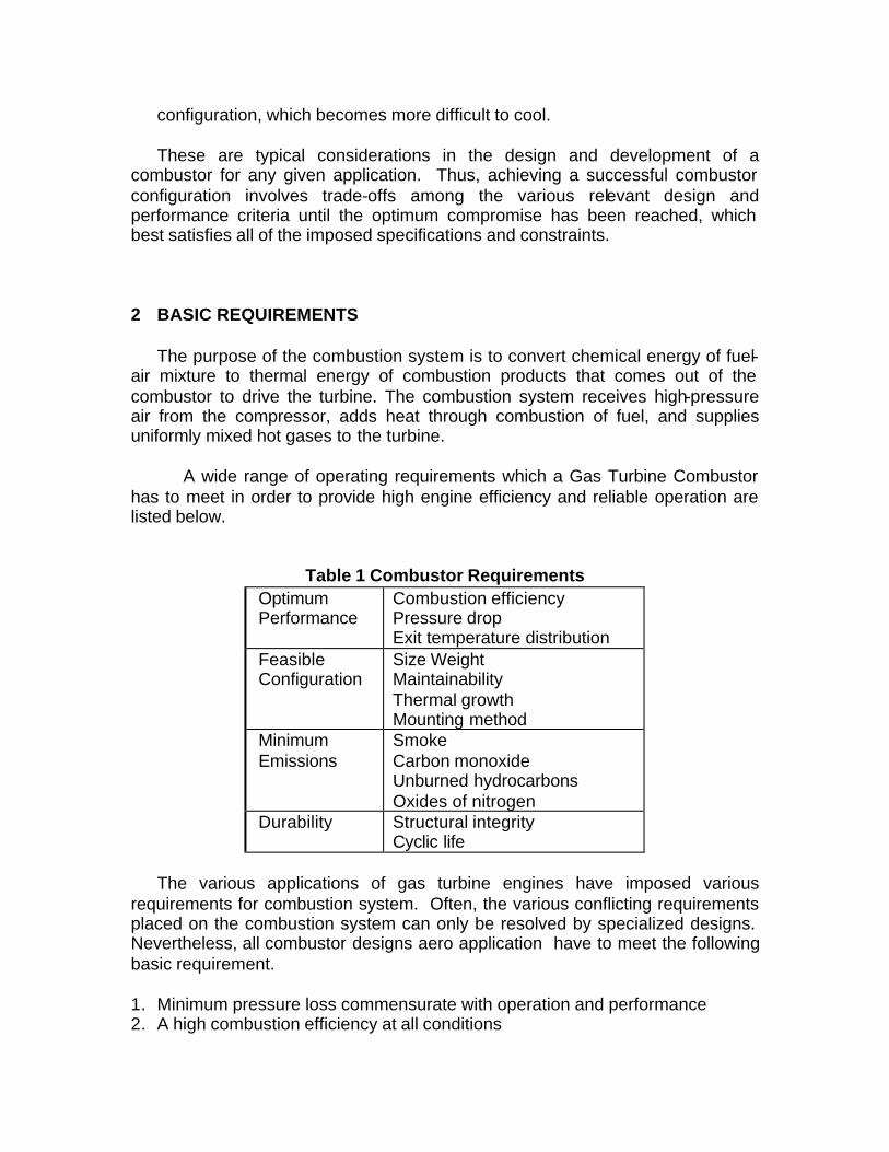
Table 1 Combustor Requirements Optimum Performance
Combustion efficiency Pressure drop Exit temperature distribution
Feasible Configuration
Size Weight Maintainability Thermal growth Mounting method
Minimum Emissions
Smoke Carbon monoxide Unburned hydrocarbons Oxides of nitrogen
Durability Structural integrity Cyclic life
The various applications of gas turbine engines have imposed various
requirements for combustion system. Often, the various conflicting requirements placed on the combustion system can only be resolved by specialized designs. Nevertheless, all combustor designs aero application have to meet the following basic requirement. 1. Minimum pressure loss commensurate with operation and performance 2. A high combustion efficiency at all conditions
3. Satisfactory ignition and relight at altitude, as well as ground starting 4. Maximum flame stability over wide range of operating conditions 5. Minimum pollutant formation at all conditions 6. A Satisfactory outlet temperature distribution tailored to the demands of the
turbine 7. Absence of smoke and solids from the exhaust, as well as deposits in
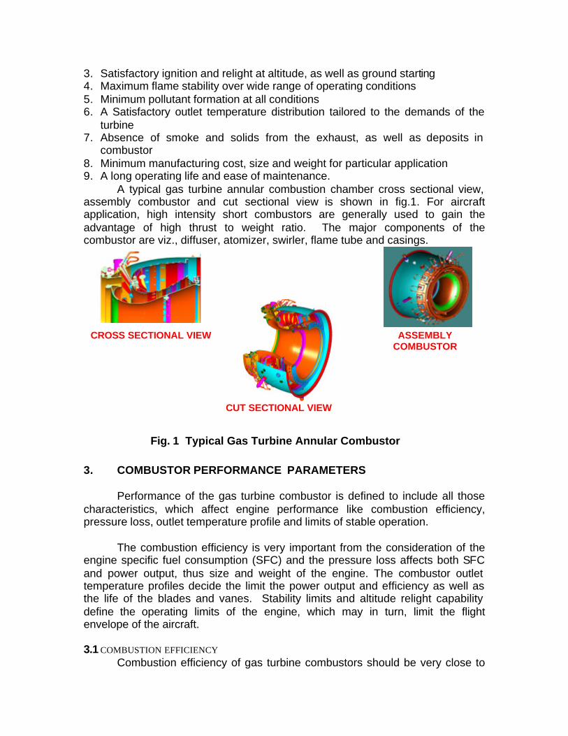
combustor 8. Minimum manufacturing cost, size and weight for particular application 9. A long operating life and ease of maintenance. A typical gas turbine annular combustion chamber cross sectional view, assembly combustor and cut sectional view is shown in fig.1. For aircraft application, high intensity short combustors are generally used to gain the advantage of high thrust to weight ratio. The major components of the combustor are viz., diffuser, atomizer, swirler, flame tube and casings.
Fig. 1 Typical Gas Turbine Annular Combustor 3. COMBUSTOR PERFORMANCE PARAMETERS Performance of the gas turbine combustor is defined to include all those characteristics, which affect engine performance like combustion efficiency, pressure loss, outlet temperature profile and limits of stable operation. The combustion efficiency is very important from the consideration of the engine specific fuel consumption (SFC) and the pressure loss affects both SFC and power output, thus size and weight of the engine. The combustor outlet temperature profiles decide the limit the power output and efficiency as well as the life of the blades and vanes. Stability limits and altitude relight capability define the operating limits of the engine, which may in turn, limit the flight envelope of the aircraft.
3.1 COMBUSTION EFFICIENCY Combustion efficiency of gas turbine combustors should be very close to
CROSS SECTIONAL VIEW ASSEMBLY COMBUSTOR
CUT SECTIONAL VIEW
100% if fuel and air are well mixed in proper proportions, ignited and given
proper time to burn. In usual industrial application, these conditions are generally
met. In the aero gas turbine engines, the combustor size is critical. It has always
proven advantageous to design for operation near the limits of combustion
intensity. Furthermore, aero engines combustor operates over a wide range of
inlet temperatures, fuel-air ratios at flight altitudes with the result that the
combustion performance may deteriorate at high altitude.
Combustion efficiency of a gas turbine depends on various processes taking place in the combustor primary zone. Combustion taking place in the primary zone can be treated as three sequential processes: evaporation, mixing and chemical reaction. All these processes can be nominally expressed and be linked with combustion efficiency as a function of:
efficiency= f (air flow rate)-1 [ (Evaporation rate)-1 + (Mixing rate)-1 + (Reaction rate)-1 ]-1
Depending on the application one or other of the processes will be limiting
with an occasional exception of a transient condition. In an aero gas turbine combustor, the atomizer design and the combustor aerodynamics generally ensures a well-mixed spray of fine droplets. This, plus the volatility of the fuel ensures that both evaporation and mixing do not limit the combustion process. Essentially they are instantaneous relative to the reaction rate. Thus, for any given set of operating conditions, the reaction kinetics determines combustion efficiency. From the given efficiency goal to meet the fuel burn, emissions and lighting, the reaction kinetics set the combustor dimension.
To make the analysis of the combustion process and for describing combustion efficiency, two approaches are most widely used: the burning velocity model and the stirred reactor model. The burning velocity model is commonly used in describing the combustion phenomena in a gas turbine combustor. This model derives an expression for the combustion efficiency as a function of a combustion loading parameter known as theta parameter. The theta parameter correlates the combustion efficiency to the operating conditions and the geometrical parameters of the combustor and is expressed by the following relation [1]:
efficiency = f (theta) And
P3 1.75 Aref Dref 0.75 exp (T3/300)
theta = __________________________
W3
3.2 Pressure drop
Pressure drop in combustion systems is usually defined as the difference in total
pressure between the compressor outlet and the turbine inlet. It consists of the
following components:
1. The diffusion loss associated with slowing the high velocity air from the
compressor outlet
2. The friction loss taken as pressure drop
3. The momentum loss (mixing loss)
4. Losses due to heat addition in the combustor.
The total pressure loss is usually in the range of 4% to 6%. Higher-
pressure losses results in both lower power output and higher SFC. An
additional pressure loss of 1% results in a loss of about 0.5% in output power
and about 0.25% increase in SFC, depending upon the engine cycle.
3.3 Temperature Profile
The average gas temperature level to achieve a target turbine life is
limited by the peak gas temperature coming out of the combustion system. For
the purposes of a satisfactory turbine design and a reasonable blade and vane
life, it is necessary to provide for a reasonable variation of gas temperature at the
entry of turbine Nozzles Guide Vanes (NGVs) in both radial and circumferential
directions. The NGVs are directly exposed to local gas temperatures and the
highest local gas temperature can affect the life of the nozzle on which it
impinges. Thus the highest local gas temperature limits nozzle design. Turbine
buckets (rotors), however, rotate past the entire nozzle ring, and effectively
average out circumferential temperature, gradients. For rotor design, the
average radial temperature profile is of important interest. However, large
circumferential temperature differences must also be avoided to minimize
excitation of rotor vibration by difference in gas velocity.
The development of the combustor exit temperature profiles depends
primarily on the mixing process between the cooling air and the hot combustion
gases in the dilution zone of the combustor. These profiles are generally
expressed in terms of two non-dimensional parameters known as Radial Pattern
Factor (RPF) and Circumferential Pattern Factor (CPF). The locus of the non-
dimensional temperature profiles is estimated using the following relations [2]:
T4cir-avg - T4avg RPF = _________________ T4avg - T3
T4l - T4avg
CPF = ____________________ T4avg - T3
Where station 3 and 4 are the combustor inlet and exit planes respectively. The
typical value of RPF and CPF are 0.12 and 0.30 respectively.
3.4 Stability limits
Fortunately, most combustors have extremely wide operating range and
are hard to blowout by normal changes in fuel flow. However, at high altitudes
the operating range of turbojet combustors narrows, so that the useful power
range of the engine is narrowed.
Combustor blowout can also occur as the result of compressor surge.
During deceleration, a large increase in fuel rate without a corresponding
increase in airflow will reduce flow through the compressor. If the compressor
goes into surge, the airflow will be reduced still more which many cause rich
blowout of the combustor or excessive turbine inlet temperature.
3.5 Altitude limits
The altitude limit of a turbojet engine is determined primarily by combustor
limitations. Although Reynolds number affects result in some loss in compressor
and turbine efficiency, this is minor compared to the large loss in combustor
efficiency, which takes place as the altitude limit is approached. The increasing
altitude, the rich and lean blowout limits converge gradually, narrowing the
usable thrust range of the engine. Combustion efficiency also declines gradually,
and at the altitude limit, becomes so low that TET needed for continued operation
cannot be generated.
The loss of efficiency at high altitude occurs because the volume required
for combustion becomes larger at extremely low pressure and consequently,
combustion reactions are only partially completed by the time the burning mixture
is quenched in the dilution zone. Poor fuel atomization may also contribute to
poor combustion at high altitude.
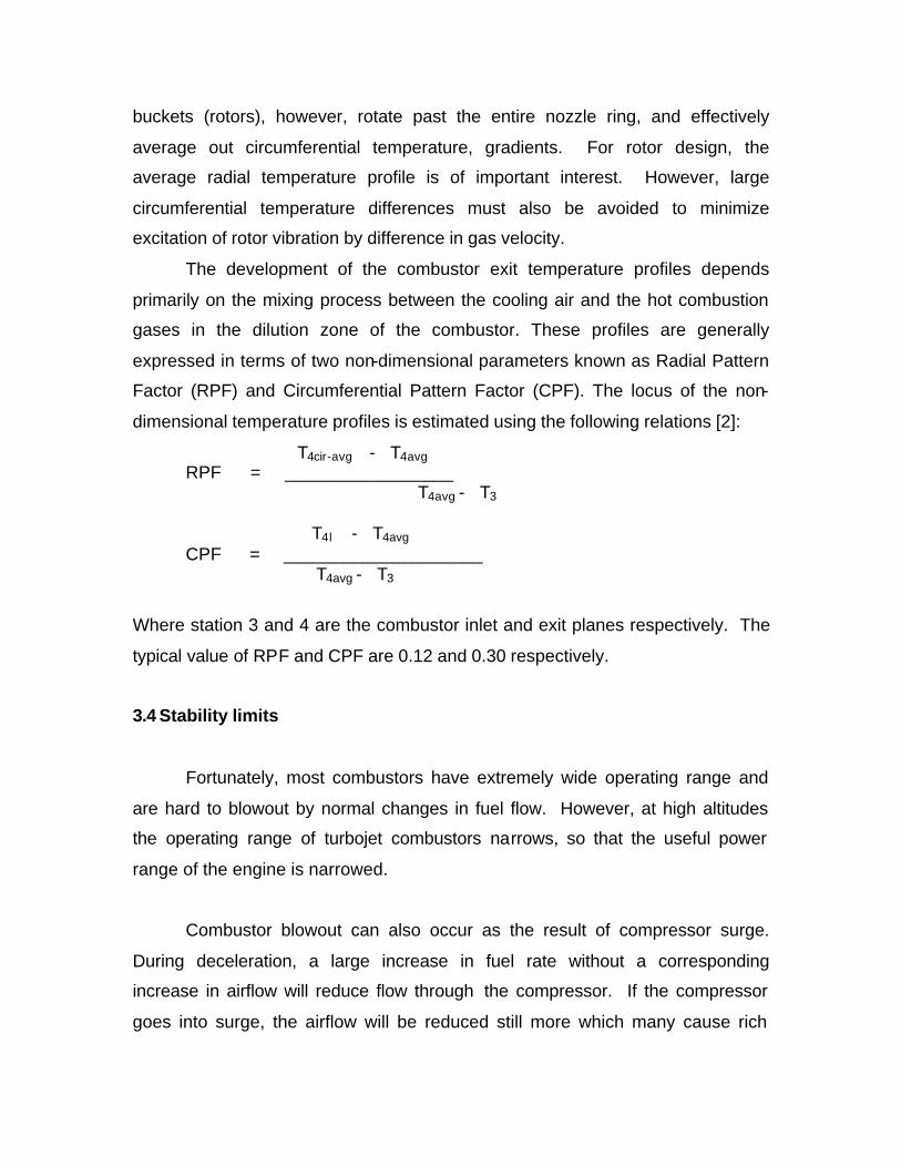
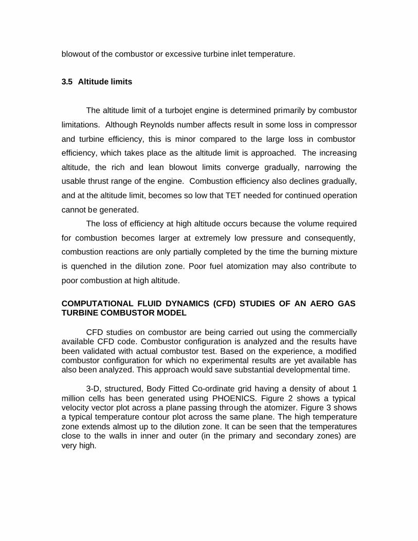
COMPUTATIONAL FLUID DYNAMICS (CFD) STUDIES OF AN AERO GAS TURBINE COMBUSTOR MODEL CFD studies on combustor are being carried out using the commercially available CFD code. Combustor configuration is analyzed and the results have been validated with actual combustor test. Based on the experience, a modified combustor configuration for which no experimental results are yet available has also been analyzed. This approach would save substantial developmental time. 3-D, structured, Body Fitted Co-ordinate grid having a density of about 1 million cells has been generated using PHOENICS. Figure 2 shows a typical velocity vector plot across a plane passing through the atomizer. Figure 3 shows a typical temperature contour plot across the same plane. The high temperature zone extends almost up to the dilution zone. It can be seen that the temperatures close to the walls in inner and outer (in the primary and secondary zones) are very high.
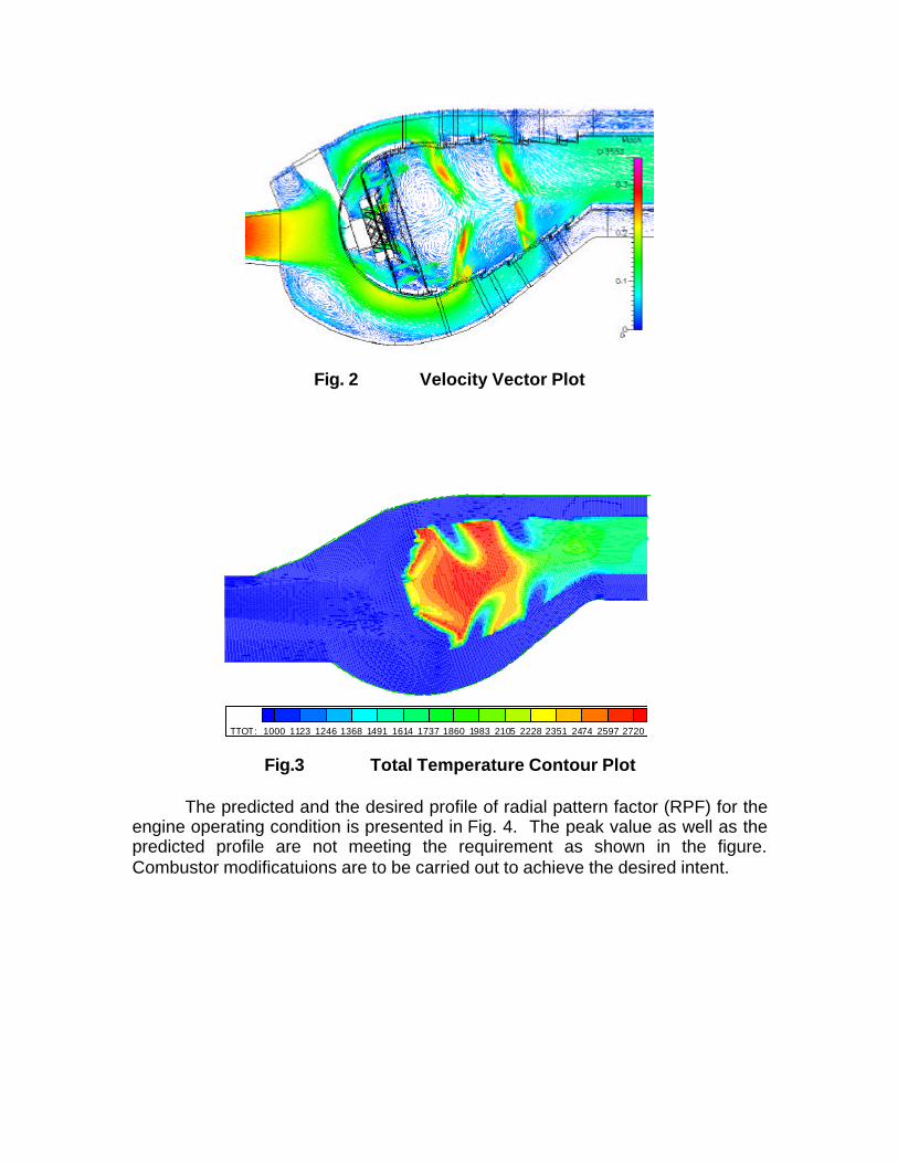
Fig. 2 Velocity Vector Plot
Fig.3 Total Temperature Contour Plot The predicted and the desired profile of radial pattern factor (RPF) for the engine operating condition is presented in Fig. 4. The peak value as well as the predicted profile are not meeting the requirement as shown in the figure. Combustor modificatuions are to be carried out to achieve the desired intent.
TTOT: 1000 1123 1246 1368 1491 1614 1737 1860 1983 2105 2228 2351 2474 2597 2720
CFD - 1 Million GridDesired
RPF Fig.4 Comparison of RPF Profiles CFD Vs Desired
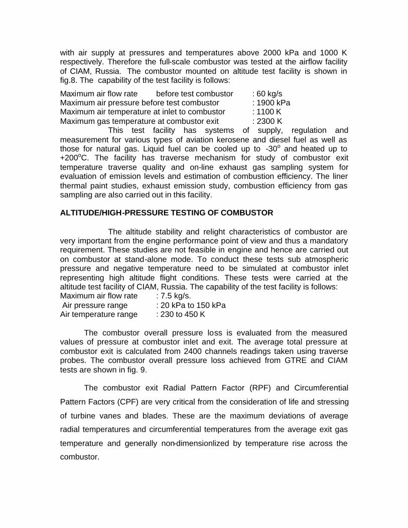
TEST FACILITIES
Flow visualization studies are carried out using water as medium and dye
and air bubbles as tracers on the 2D Water table facility by simulating Froude
number for optimizing the diffuser and subsequently by simulating Reynolds
number on the 3D water tunnel test facility where the flow through liner holes and
their interactions, mixing intensity inside the flame tube etc. are studied. The
typical flow patterns observed inside the combustion chamber both on 2D and 3D
rigs are shown in fig 5 and fig 6. The pressure losses are evaluated and mass
flow splits are computed. This is used an aiding tool for design finalization /
optimization which has reduced the actual developmental time and cost
enormously. This can also be used for as an experimental validation tool for the
CFD studies
% A
nnul
us H
eigh
t
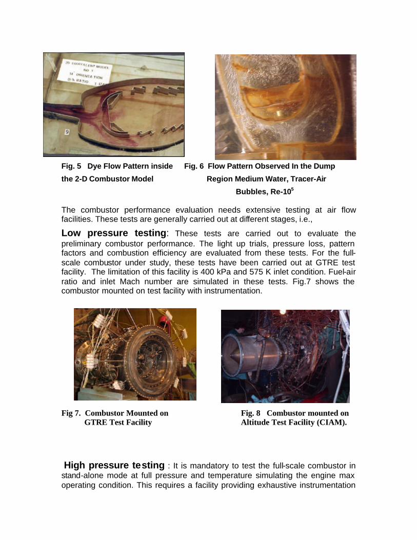
Fig. 5 Dye Flow Pattern inside Fig. 6 Flow Pattern Observed In the Dump
the 2-D Combustor Model Region Medium Water, Tracer-Air
Bubbles, Re-105
The combustor performance evaluation needs extensive testing at air flow facilities. These tests are generally carried out at different stages, i.e.,
Low pressure testing: These tests are carried out to evaluate the preliminary combustor performance. The light up trials, pressure loss, pattern factors and combustion efficiency are evaluated from these tests. For the full-scale combustor under study, these tests have been carried out at GTRE test facility. The limitation of this facility is 400 kPa and 575 K inlet condition. Fuel-air ratio and inlet Mach number are simulated in these tests. Fig.7 shows the combustor mounted on test facility with instrumentation.
Fig 7. Combustor Mounted on Fig. 8 Combustor mounted on GTRE Test Facility Altitude Test Facility (CIAM).
High pressure testing : It is mandatory to test the full-scale combustor in stand-alone mode at full pressure and temperature simulating the engine max operating condition. This requires a facility providing exhaustive instrumentation
with air supply at pressures and temperatures above 2000 kPa and 1000 K respectively. Therefore the full-scale combustor was tested at the airflow facility of CIAM, Russia. The combustor mounted on altitude test facility is shown in fig.8. The capability of the test facility is follows:
Maximum air flow rate before test combustor : 60 kg/s Maximum air pressure before test combustor : 1900 kPa Maximum air temperature at inlet to combustor : 1100 K Maximum gas temperature at combustor exit : 2300 K This test facility has systems of supply, regulation and measurement for various types of aviation kerosene and diesel fuel as well as those for natural gas. Liquid fuel can be cooled up to -30o and heated up to +200oC. The facility has traverse mechanism for study of combustor exit temperature traverse quality and on-line exhaust gas sampling system for evaluation of emission levels and estimation of combustion efficiency. The liner thermal paint studies, exhaust emission study, combustion efficiency from gas sampling are also carried out in this facility. ALTITUDE/HIGH-PRESSURE TESTING OF COMBUSTOR The altitude stability and relight characteristics of combustor are very important from the engine performance point of view and thus a mandatory requirement. These studies are not feasible in engine and hence are carried out on combustor at stand-alone mode. To conduct these tests sub atmospheric pressure and negative temperature need to be simulated at combustor inlet representing high altitude flight conditions. These tests were carried at the altitude test facility of CIAM, Russia. The capability of the test facility is follows: Maximum air flow rate : 7.5 kg/s. Air pressure range : 20 kPa to 150 kPa Air temperature range : 230 to 450 K The combustor overall pressure loss is evaluated from the measured values of pressure at combustor inlet and exit. The average total pressure at combustor exit is calculated from 2400 channels readings taken using traverse probes. The combustor overall pressure loss achieved from GTRE and CIAM tests are shown in fig. 9. The combustor exit Radial Pattern Factor (RPF) and Circumferential
Pattern Factors (CPF) are very critical from the consideration of life and stressing
of turbine vanes and blades. These are the maximum deviations of average
radial temperatures and circumferential temperatures from the average exit gas
temperature and generally non-dimensionlized by temperature rise across the
combustor.
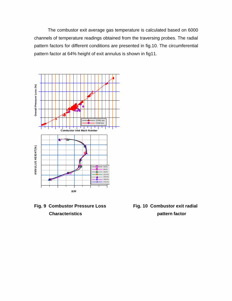
The combustor exit average gas temperature is calculated based on 6000
channels of temperature readings obtained from the traversing probes. The radial
pattern factors for different conditions are presented in fig.10. The circumferential
pattern factor at 64% height of exit annulus is shown in fig11.
Combustor inlet Mach Number
Ove
rall
Pre
ssu
re L
oss
(%
)
GTRE test CIAM test
RPF
AN
NU
LU
S H
EIG
HT
(%)
448 kPa
685 kPa
756 kPa
1241 kPa
1462 kPa
1655 kPa
1751 kPa
Fig. 9 Combustor Pressure Loss Fig. 10 Combustor exit radial
Characteristics pattern factor
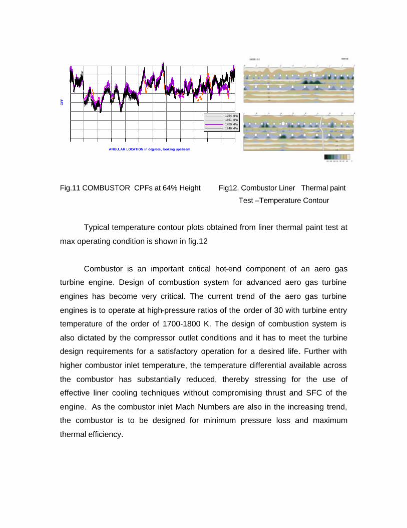
ANGULAR LOCATION in deg rees, looking upstream
CP
F
1754 kPa1651 kPa1459 kPa1240 kPa
Fig.11 COMBUSTOR CPFs at 64% Height Fig12. Combustor Liner Thermal paint
Test –Temperature Contour
Typical temperature contour plots obtained from liner thermal paint test at
max operating condition is shown in fig.12
Combustor is an important critical hot-end component of an aero gas
turbine engine. Design of combustion system for advanced aero gas turbine
engines has become very critical. The current trend of the aero gas turbine
engines is to operate at high-pressure ratios of the order of 30 with turbine entry
temperature of the order of 1700-1800 K. The design of combustion system is
also dictated by the compressor outlet conditions and it has to meet the turbine
design requirements for a satisfactory operation for a desired life. Further with
higher combustor inlet temperature, the temperature differential available across
the combustor has substantially reduced, thereby stressing for the use of
effective liner cooling techniques without compromising thrust and SFC of the
engine. As the combustor inlet Mach Numbers are also in the increasing trend,
the combustor is to be designed for minimum pressure loss and maximum
thermal efficiency.