Embed Size (px)
Citation preview
i
DEVELOPMENT OF A ROAD LINE DETECTION ALGORITHM FOR
MONITORING DRIVING PATTERN
NAJWA BINTI ISMAIL
This Report Is Submitted In Partial Fulfilment of the Requirements for the Award
of Bachelor of Electronic Engineering (Computer Engineering) With Honours
Faculty of Electronic and Computer Engineering
University of Technical Malaysia Melaka
June 2016
ii
iii
iv
v
Special dedication to my family, supervisor Dr Masrullizam Bin Mat Ibrahim and
friends in FKEKK for their supports and help.
vi
ACKNOWLEDGEMENT
I would like to express my grateful to Allah S.W.T for blessing me with a good
health, knowledge and strength to finish my thesis writing and final year project
successfully.
My special thanks to my supervisor, Dr Masrullizam Bin Mat Ibrahim for
conducting me during this final year project studies. A lot of guidance and knowledge
provided by him, helped me during my final year project studies. I would like to thanks
to all lecturers who are involved for giving their opinions, information and suggestions
in my project.
I would like to thanks to my parents for their support especially morality support
throughout my studies. They have been my inspiration since I started my degree studies
in University of Technical Malaysia Melaka (UTeM). Besides, a very special dedication
I rewarded to all master students who helped me a lot in completing this project. This
thesis is a part of their contribution.
Lastly, I would like to thanks to UTeM for giving me the very best facilities
during my studies, and my dearest friends who helped me a lot to complete this thesis
writing.
vii
ABSTRACT
Lately, the road accidents contribute a very high accident rate which involve in
death. The main cause because of human error such as distraction and careless
behaviour while driving is the biggest factor of road accidents. Road line detection
system is one of the systems of the Automated Car Driver Assisted system. The Road
line detection is aimed to give warning to the drivers when the vehicle starts to veering
off from the actual lane towards lane boundary without any intention of the driver to
change from the initial lane path. This system is aimed to reduce the number of road
accident that are frequently happened because of the driver behaviour, distraction and
drowsiness. This Road line detection system can also be advantageous in many real
world applications such as security control freeway, driving training, autonomous
navigation and the visually impaired assistant. The Road line detection system is based
on visual sensor using camera that is usually placed behind the windshield of the
vehicle, laser sensor which is attached in front of the vehicle and infrared sensor which
is attached either behind the windshield or beneath the vehicle. While driving, it is
unknown whether the driver driving with normal behaviour or not. Hence, this project is
aiming on the lane detecting and tracking by using vision sensor. This main purpose is
to study the technique used to detect the road road line detection and tracking by using
vision sensor (camera). In order to achieve the main objective, the other objectives must
be achieved are to develop the best algorithm of the road road line detection and lane
tracking and to read the driving pattern using the developed algorithm. Overall, this
system is able to enhance lane boundary information to drivers.
viii
ABSTRAK
Pada masa kini, kemalangan jalan raya menyumbang kepada kadar kemalangan
yang mengakibatkan kematian. Punca utama adalah kerana keadaan pemandu seperti
gangguan dan kecuaian ketika memandu merupakan faktor kemalangan yang paling
besar. Sistem Pengesanan Jalan adalah salah satu sistem Bantuan Pemanduan Kereta
Berautonomi. Matlamat Sistem Pengesanan Jalan ini adalah untuk memberi amaran
kepada pemandu apabila kenderaan mula bergerak keluar dari jalan tanpa niat untuk
menukar laluan. Sistem ini bertujuan untuk mengurangkan kadar kemalangan jalan raya
yang disebabkan sikap pemandu, sebarang gangguan dan keletihan pemandu ketika
memandu. Sistem ini boleh diaplikasikan kepada situasi sebenar seperti kawalan
keselamatan lebuh raya, latihan pemanduan, navigasi autonomi dan pembantu kepada
pengguna cacat penglihatan. Malah, Sistem Pengesanan Jalan ini berdasarkan sensor
visual pada kebiasanya dipasang di belakang cermin depan kenderaan, sensor lesor yang
dipasang pada bahagian hadapan kenderaan dan penderia inframerah yang dipasang
sama ada di belakang cermin depan atau di bawah kenderaan. Semasa memandu
kenderaan, ia tidak diketahui sama ada pemandu memandu dengan kelakuan normal
ataupun tidak normal. Maka, projek ini tertumpu kepada pengesanan dan penjejakan
jalan menggunakan sensor visual. Tujuan utama adalah untuk mempelajari teknik-teknik
yang boleh digunakan dalam pengesanan dan penjejakan jalan menggunakan sensor
visual (kamera). Untuk mencapai objektif utama, objektif lain mestilah dicapai bagi
mendapatkan algoritma dalam sistem pengesanan dan penjejakan jalan ini untuk
menganalisa bentuk pemanduan. Kesimpulannya, sistem ini boleh memberi informasi
mengenai kedudukan kereta di atas jalan raya kepada para pemandu.
ix
TABLE OF CONTENT
CHAPTER TITLE PAGE
TITLE i
SUPERVISOR CONFIRMATION ii
ACKNOWLEDGEMENT vi
ABSTRACT vii
ABSTRAK viii
TABLE OF CONTENT x
LIST OF FIGURES xi
I INTRODUCTION
1.1 PROJECT INTRODUCTION 1
1.2 OBJECTIVES 2
1.3 PROBLEM STATEMENT 2
1.4 SCOPE OF PROJECT 2
1.5 PROJECT LIMITATION 3
1.6 REPORT STRUCTURE 3
II LITERATURE REVIEW
2.1 ROAD LINE DETECTION 4-5
2.1.1 STUDY RESEARCH 6
2.1.1.1 LINEAR FUZZY SPACE MATHEMATICS 6
2.1.1.2 LANE FEATURE EXTRACTION & GAUSSIAN SUM
PARTICLE FILTER 7-8
2.1.1.3 ROBUST ROAD LANE DETECTION & LOW
ILLUMINATION CONDITIONS 8-9
2.1.1.4 H-MAXIMA & IMPROVED HOUGH TRANSFORM 9
x
2.2 SUMMARY OF LITERATURE REVIEW 10
III RESEARCH METHODOLOGY
3.1 PROJECT PLANNING 11-12
3.2 PROJECT FLOWCHART 13
3.3 RECORD LANE 14
3.4 ROAD LINE DETECTION 14
3.5 IMAGE PREPROCESSING 15-21
3.5.1 REGION OF INTEREST SETUP 16
3.5.2 REDUCE NOISE 17
3.5.3 IMAGE FILTERING 17-18
3.5.4 EDGE DETECTION 19
3.5.5 THRESHOLDING 20
3.5.6 FEATURE EXTRACTION 21
3.6 HOUGH TRANSFORM 22-23
IV RESULT & DISCUSSION
4.1 ROAD LINE DETECTION 24
4.1.1 IMAGE PREPROCESSING 24
4.1.2 EDGE DETECTION 25
4.1.3 HOUGH TRANSFORM 26
4.2 THE ALGORITHMS 27-33
4.3 GRAPHICAL USER INTERFACE 34
4.4 CONCLUSION 35
V CONCLUSION & RECOMMENDATION
xi
5.1 CONCLUSION 36
5.2 RECOMMENDATION 37
REFERENCES 38-40
APPENDIX A 41-48
APPENDIX B 48-57
xii
LIST OF FIGURE
NO TITLE PAGE
2.1 Blind spot monitoring using sensor 5
2.2 Two primary „line like‟ fuzzy points 6
2.3 Vanishing points using GSPF 7
2.4 Method to Calculate Vertical Gradient in Feature Extraction 8
2.5 Computed & predicted lane based on vertical gradient 9
3.1 Gantt chart 12
3.2 Project flowchart 13
3.3 Recorded image 14
3.4 Assumption flow of line detection process 14
3.5 ROI (Region of Interest Setup) 16
3.6 Original & filtered image 18
3.7 Original & thresholded image 20
3.8 Line axis in Hough 23
4.1 Detected line 25
4.2 Detected line in edge 25
4.3 Line detected in Hough 26
4.4 Flow diagram in algorithms 27
4.5 Initial line marker on first frame 27
4.6 Left and right boundaries 27
4.7 Left and right intersected to form angle 28
4.8 Car position indicator 29
4.9 Final output (right) 30
4.10 Final output (left) 30
xiii
4.11 Lane crossing 31
4.12 Workspace of algorithm 32
4.13 Workspace of algorithm 33
4.14 GUI before processing video 34
4.15 GUI after processing video 35
1
CHAPTER 1
INTRODUCTION
1.1 Project Introduction
Research shows that accident happens are caused by human behaviours that is
because of driver‟s lacking skill. To ensure the safety and security of automobiles
and passengers, apparently, some car system technologies have been developed such
as forward collision prevention and lane keeping assist. The technologies may help
preventing accidents, thus, reducing accident rates.
Traffic accidents have become one of the most serious problems. The reason is
that most accidents occur due to slackness of the driver. Careless and slack driving
can push other drivers and passengers at risk on the roads. More and more
misfortunes could be escaped if such risky driving condition is detected early and
warned especially to the drivers. Mostly, cameras and speed sensors are being used
for observing and detecting drivers who surpassed the permitted speed limit on roads
and motorways.
Basically, this project, the road line detection project is designed to help
prevent a sleepy or distracted driver from accidentally drifting out of his or her lane.
Most importantly, this project is to alert drivers. The analysed driving pattern can
show the condition of the driver, either in good driving condition or in dangerous
driving condition. This is one of the way to monitor the driving condition.
A camera is used to capture images along the road parallel with cars. It uses
camera to detect lane markings and triggers a warning if the car try to penetrate and
2
out of the line. Besides, the system will also trigger even when the car approaches
near to the line. This can also be used for a road detection in urban traffic.
An algorithm of a road line detection algorithm is analysed using MATLAB
Software. Full coding of MATLAB need to be programmed in order to give the best
result. The algorithm produced in MATLAB software is expected to be able to detect
road line successfully. It is then able to show output based on Graphical User
Interface (GUI).
1.2 Objectives of this project
The main goal of this project is to use the best method of the road line
detection system. Specifically, the main objectives of this project are:
• To develop road line detection algorithm.
• To analyse and evaluate performance of the developed algorithm.
• To read the driving pattern using developed algorithm.
1.3 Problem Statement
While driving, it is unknown whether the driver is driving in the correct
behaviour or not. Human error such as distraction while driving is the biggest factor
of road accidents. Mainly, this project is a mechanism to alert drivers to help
preventing a sleepy or distracted driver from accidentally drifting out of his or her
lane. This may results in reducing numbers of accident caused by human error.
Therefore, a road line detection is focusing on detecting and tracking with the use of
camera vision sensor.
1.4 Scope of Project
The scope of this project is to detect the road line. At first, a camera is used to
record road line. The camera recording is during the day time in an offline mode.
A full algorithm based on a specific method is programmed using MATLAB
software. The algorithm is used to detect all white road line. After that, the driving
pattern is read based on how the vehicle move towards the line.
3
1.5 Project Limitation
This project has a limitation of the study. In this project, only about a kilometre
of recorded road lane will be used for testing. Only MATLAB software will be used
to analyse the algorithm.
Besides, the camera recording is during an offline mode. This means that the
algorithm is programmed and analysed only for recorded image.
1.6 Report Structure
This thesis is the combination of five chapters that contains the introduction,
literature review, methodology, result and discussion and the last chapter is the
conclusion and recommendation of this project.
Chapter 1 covers the introduction to the project. In this chapter, we will explain
the background and objectives of the project. The concept behind this project and an
overall overview of the project also will also be discussed within this chapter.
Chapter 2 tells about the literature review of the road line detection upon
previous research done. Based on the research, all methods that have been done can
be referred well. Chapter 3 will explain about the project methodology. This chapter
will show the steps and flows for problem solving technique in such a specific
method. The method used will also be discussed.
Chapters 4 describes the outcome results from this project and this may justify
the project performance so that it meets the objectives of the research. Then, the
behaviour of drivers can be analysed well too. Finally, Chapter 5 concludes the
whole research and proposes the future progress of the project.
4
CHAPTER 2
LITERATURE REVIEW
This chapter will explain and discuss about the literature or research which is related
to the road line detection including the method used that has been studied from
different resources to perform this project.
2.1 Road Line Detection Overview
Road line detection is very important to drivers. Road line detection is a well-
researched area of computer vision with application in autonomous vehicles and
driver support systems as one of safety features.
There are some of the most remarkable improvements in technologies and they
can aid a safer driving includes Adaptive Cruise Control, Anti-Lock Braking System
(ABS), Automatic Parking and Blind Spot Monitoring [3]. For example, adaptive
cruise control systems help to sense vehicles forward and regulate the speed to retain
a safe following distance while blind spot monitor are the sensors around vehicles
that give warning when nearby car is detected.
5
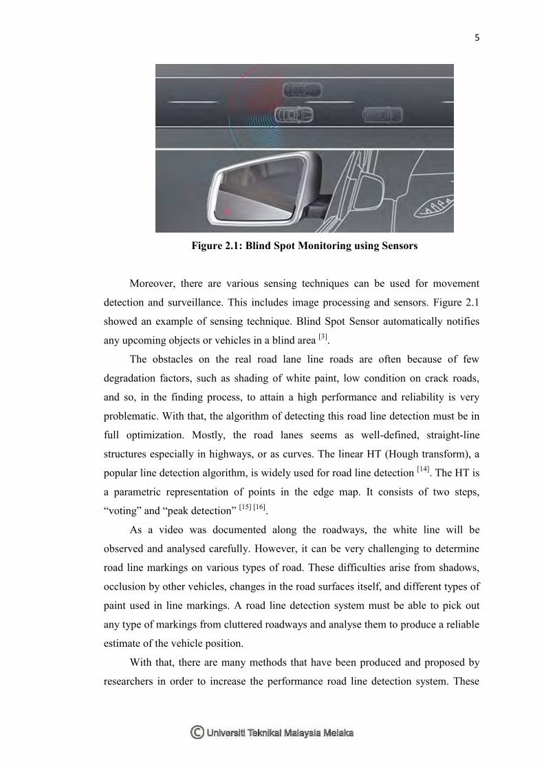
Figure 2.1: Blind Spot Monitoring using Sensors
Moreover, there are various sensing techniques can be used for movement
detection and surveillance. This includes image processing and sensors. Figure 2.1
showed an example of sensing technique. Blind Spot Sensor automatically notifies
any upcoming objects or vehicles in a blind area [3].
The obstacles on the real road lane line roads are often because of few
degradation factors, such as shading of white paint, low condition on crack roads,
and so, in the finding process, to attain a high performance and reliability is very
problematic. With that, the algorithm of detecting this road line detection must be in
full optimization. Mostly, the road lanes seems as well-defined, straight-line
structures especially in highways, or as curves. The linear HT (Hough transform), a
popular line detection algorithm, is widely used for road line detection [14]. The HT is
a parametric representation of points in the edge map. It consists of two steps,
“voting” and “peak detection” [15] [16].
As a video was documented along the roadways, the white line will be
observed and analysed carefully. However, it can be very challenging to determine
road line markings on various types of road. These difficulties arise from shadows,
occlusion by other vehicles, changes in the road surfaces itself, and different types of
paint used in line markings. A road line detection system must be able to pick out
any type of markings from cluttered roadways and analyse them to produce a reliable
estimate of the vehicle position.
With that, there are many methods that have been produced and proposed by
researchers in order to increase the performance road line detection system. These
6
methods are believed to be the most effective methods to be approachable in the road
line detection system.
2.1.1 Research Study
The study research based on road line detection system has been widely
explored by researchers, the researchs are taking into consider of different techniques
and methods to be perfomed. Mostly, the research field explored are for enhancing
the analysis of image and video processing.
2.1.1.1. Linear Fuzzy Space Mathematics
Linear Fuzzy method is a mathematical model of inexact point objects to
determine the maximal space between inexact point objects. The best way to describe
a road is to identify lane marks.
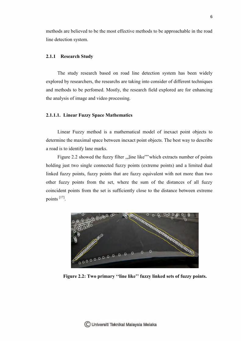
Figure 2.2 showed the fuzzy filter „„line like‟‟ which extracts number of points
holding just two single connected fuzzy points (extreme points) and a limited dual
linked fuzzy points, fuzzy points that are fuzzy equivalent with not more than two
other fuzzy points from the set, where the sum of the distances of all fuzzy
coincident points from the set is sufficiently close to the distance between extreme
points [17].
Figure 2.2: Two primary ‘‘line like’’ fuzzy linked sets of fuzzy points.
7
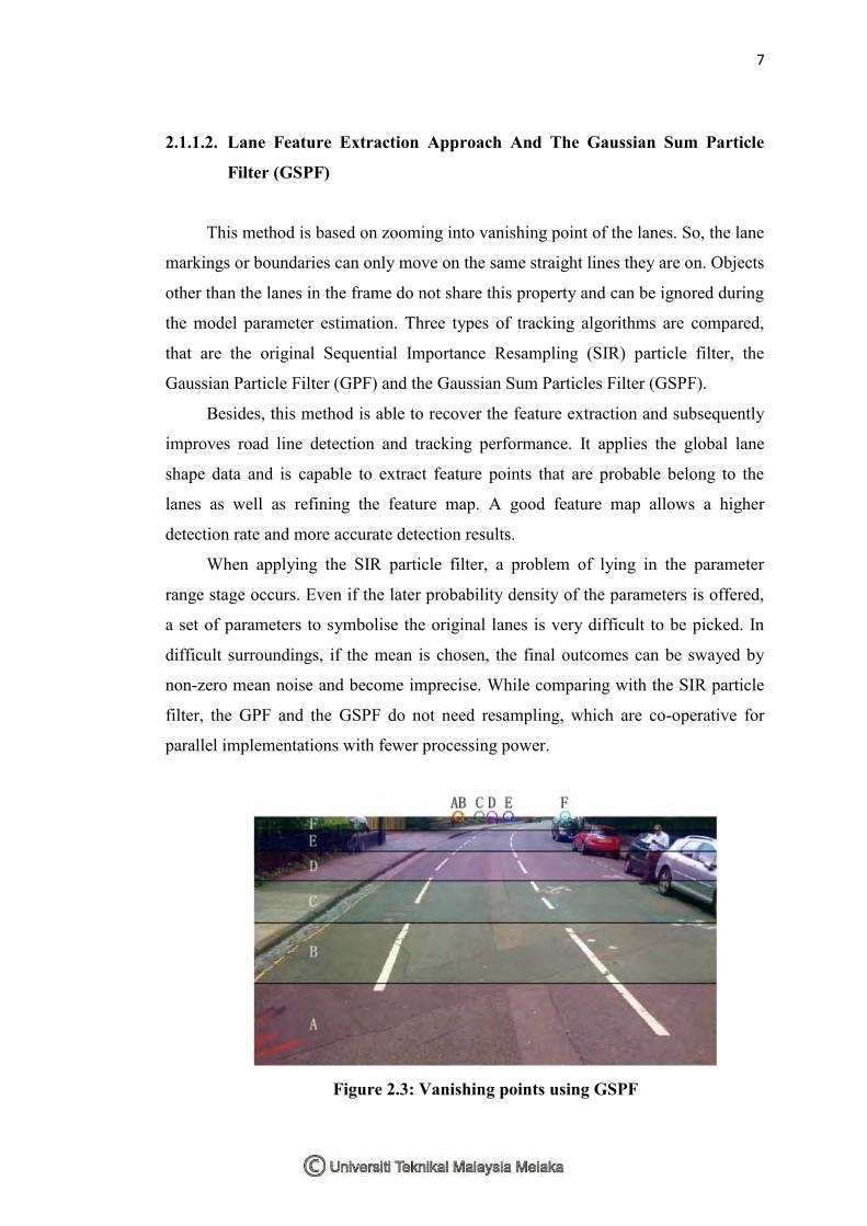
2.1.1.2. Lane Feature Extraction Approach And The Gaussian Sum Particle
Filter (GSPF)
This method is based on zooming into vanishing point of the lanes. So, the lane
markings or boundaries can only move on the same straight lines they are on. Objects
other than the lanes in the frame do not share this property and can be ignored during
the model parameter estimation. Three types of tracking algorithms are compared,
that are the original Sequential Importance Resampling (SIR) particle filter, the
Gaussian Particle Filter (GPF) and the Gaussian Sum Particles Filter (GSPF).
Besides, this method is able to recover the feature extraction and subsequently
improves road line detection and tracking performance. It applies the global lane
shape data and is capable to extract feature points that are probable belong to the
lanes as well as refining the feature map. A good feature map allows a higher
detection rate and more accurate detection results.
When applying the SIR particle filter, a problem of lying in the parameter
range stage occurs. Even if the later probability density of the parameters is offered,
a set of parameters to symbolise the original lanes is very difficult to be picked. In
difficult surroundings, if the mean is chosen, the final outcomes can be swayed by
non-zero mean noise and become imprecise. While comparing with the SIR particle
filter, the GPF and the GSPF do not need resampling, which are co-operative for
parallel implementations with fewer processing power.
Figure 2.3: Vanishing points using GSPF
8
The lane boundaries in each image segment are treated as piecewise straight
lines. Thus, the correct vanishing point positions, as in Figure 2.3, is used for
dissimilar image sections are able to be found so that the zooming process for
different image sections can also be divided. The proposed feature extraction method
produces feature maps with the least noise which permits the act of all three tracking
algorithms to be enriched dramatically [18].
2.1.1.3. Robust Road line detection and Low Illumination Conditions Using
Local Gradient Features
This method is using processing grayscale images of local gradient structures,
characteristic spectrum of lanes, and linear prediction. All points on the nearby right
and left lane are documented via the local gradient descriptors. A simple linear
prediction model is positioned to estimate the path of lane markers.
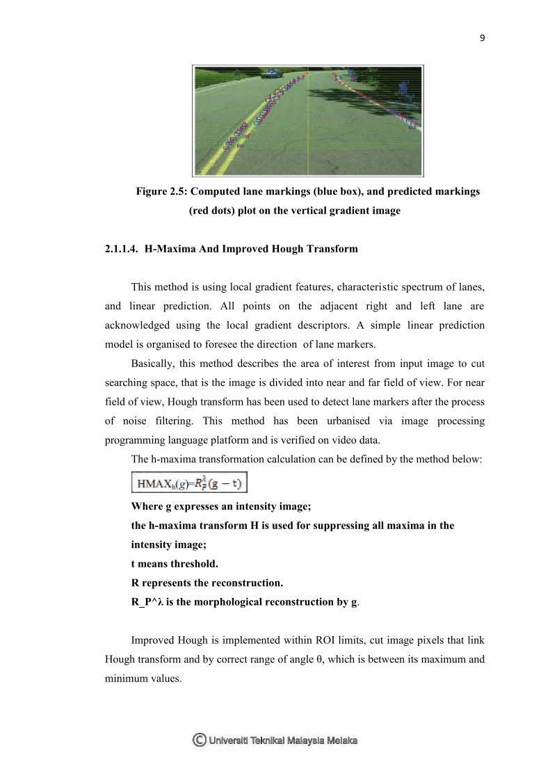
This method starts by extracting the single frames from video and processing
every frame to identify and track the road lane markers. The vertical gradient is
chosen to eliminate effect of silhouettes along the road which are frequently
horizontal shape as shown in Figure 2.5. To differentiate between computed lane
markings and predicted markings, blue and red box-shaped are used.
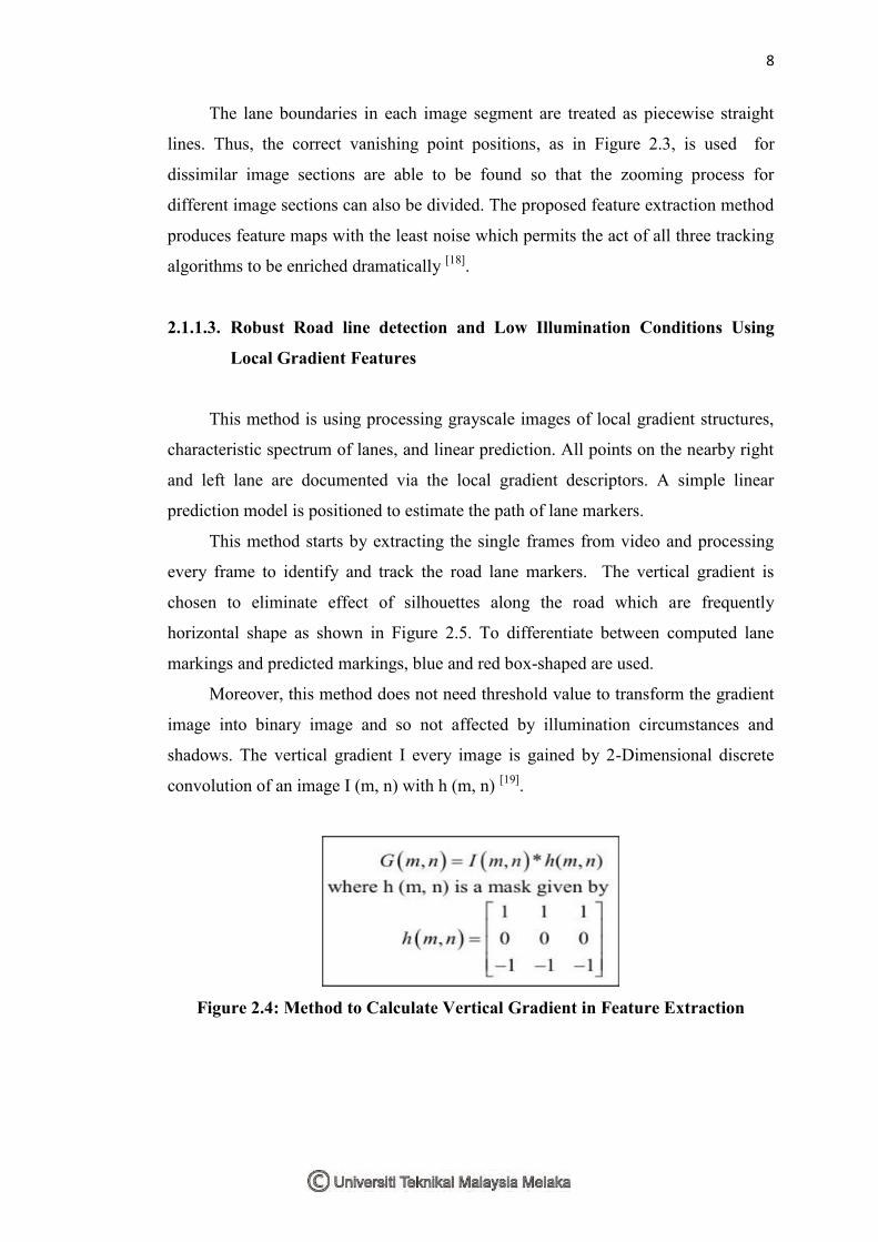
Moreover, this method does not need threshold value to transform the gradient
image into binary image and so not affected by illumination circumstances and
shadows. The vertical gradient I every image is gained by 2-Dimensional discrete
convolution of an image I (m, n) with h (m, n) [19].
Figure 2.4: Method to Calculate Vertical Gradient in Feature Extraction
9
Figure 2.5: Computed lane markings (blue box), and predicted markings
(red dots) plot on the vertical gradient image
2.1.1.4. H-Maxima And Improved Hough Transform
This method is using local gradient features, characteristic spectrum of lanes,
and linear prediction. All points on the adjacent right and left lane are
acknowledged using the local gradient descriptors. A simple linear prediction
model is organised to foresee the direction of lane markers.
Basically, this method describes the area of interest from input image to cut
searching space, that is the image is divided into near and far field of view. For near
field of view, Hough transform has been used to detect lane markers after the process
of noise filtering. This method has been urbanised via image processing
programming language platform and is verified on video data.
The h-maxima transformation calculation can be defined by the method below:
Where g expresses an intensity image;
the h-maxima transform H is used for suppressing all maxima in the
intensity image;
t means threshold.
R represents the reconstruction.
R_P^λ is the morphological reconstruction by g.
Improved Hough is implemented within ROI limits, cut image pixels that link
Hough transform and by correct range of angle θ, which is between its maximum and
minimum values.
10
2.2 Summary of the Literature Review
After the literature review process regarding the project algorithms, there are
few methods that are suitable to be used as references. The method that is chosen for
this project is the detection of road lane in a video processing by Parajuli, A., Celenk,
M., & Riley, H. B. [19] due to the better efficiency in offline mode algorithms and
can track roads lane markers of various shape whether in curved or straight lines and
trace exact lane marking points on each horizontal image line which is unaffected by
shadows.
The practice of the pre-processing stage to filter the interference and noise in
the footage recorded for better efficiency should made. Then, the pre-processing for
road line detection should also be applied in a region of interest (ROI) and edge
detection to ease the road line detection process.
11
CHAPTER 3
METHODOLOGY
In this chapter, the methodology step includes the collection of theories on the image
pre-processing and classification of driving pattern based on line detection. It also
includes about the MATLAB used for reading the driving pattern using developed
algorithm. The information can be done from searching the related topic literatures,
white papers, technical and proceeding papers, product data sheets, web pages and
also through other projects. The methodology is referred as a guideline before the
final result can be successfully obtained.
3.1 Project Planning
This project has been planned before it gets started in order to obtain the
expected result. The project planning is represented in the Gantt chart. Table 3.1
shows the project planning since semester 1 to semester 2 in the year of 2015 and
2016.