Embed Size (px)
Citation preview

U.P.B. Sci. Bull., Series C, Vol. 79, Iss. 2, 2017 ISSN 2286-3540
DEVELOPMENT OF A NANOSATELLITE ELECTRICAL
POWER SYSTEM USING Li-ION SUPERCAPACITORS
Mihai TOTU1, Octavian DONŢU2, Eugenia EFTIMIE TOTU3*
This paper presents an innovative solution for electric power system (EPS)
based on supercapacitors, developed for nanosatellites. Considering 3 different
configurations of possible redundant systems for EPS, using Li-Ion supercapacitors,
with their advantages and faults, it has been chosen the best one which allowed
further testing of a nanosatellite model in light and in dark conditions. Testing and
analyzing the EPS, it was possible to select the appropriate conversion circuit in
order to get the best efficiency. We have proved that there are handy solutions for
supercapacitor based EPS as primary source for electrical power system storage.
Keywords: electric power system, Li-Ion supercapacitor, CubeSat, solar panels,
DC-DC convertors
1. Introduction
Nowadays, almost all of the electrical power system (EPS) used in
satellites or nanosatellites are developed based on rechargeable batteries [1]. The
main issues regarding the usage of rechargeable batteries in space refers to: the
commonly limited life of the batteries due to numerous continuous
charging/discharging cycles in a short period of time; extreme functioning
temperatures (from - 400C to 700C) limiting their performance; capacity to supply
larger power for short period of time. Taking into consideration the high number
of daily charging/discharging cycles that rechargeable batteries had to support, for
instance, at an average of 14-15 cycles for low earth orbit (LEO) [2] rechargeable
batteries should support over 1,000 cycles in less of 72 days [3]. As most of the
CubeSat missions have an average experimenting term of three months, with a
lifetime expectancy of years, the stress on the rechargeable batteries
performances, subsequently on the EPS, is very high. In mean time, functioning at
low temperatures, these rechargeable batteries determine application of
1 PhD Student, Dept. of Mechatronics and Precision Mechanics, University POLITEHNICA of
Bucharest, Romania, e-mail: [email protected] 2 Professor, Dept. of Mechatronics and Precision Mechanics, University POLITEHNICA of
Bucharest, Romania, e-mail: [email protected] 3 Professor, Dept. of Analytical Chemistry and Environmental Engineering, University
POLITEHNICA of Bucharest, Romania, corresponding author: e-mail:

158 Mihai Totu, Octavian Donţu, Eugenia Eftimie Totu
unconventional solutions [1]. For instance, an electrical resistance wrapped
around the rechargeable batteries can be used for their heating. Such electrical
energy is used in order to bring the rechargeable batteries within the functioning
temperatures range, although it could also be used for some other practical
purposes [4]. Various tasks as: data transmissions, processor or high power sensor
testing or an experimental module, could overpass the limits of the present
rechargeable batteries. The ability of EPS module inside a CubeSat [5] for
supplying in certain situations instantaneous electrical power of over 50W should
not be ignored, much more that such task could not be fulfilled by classic Ni-Mh
or Li-Ion rechargeable batteries.
Taking into consideration all these aspects, we proposed to use
supercapacitors as unique source for viable electrical energy storage. Such devices
usually have at least 50,000 charging/discharging cycles and they function within
a temperature range from -400C to +700C, with even a larger range for EDLC
supercapacitors. Another advantage of such devices is the capacity to supply a
much higher electrical current for short periods of time.
2. Experimental development of the electrical power system (EPS)
with supercapacitors for nanosatellites
The EPS could be designed in various modes according to the conception
and function principle considered.
2.1. Solution A for EPS
The simplest implementation for EPS is presented in Fig. 1.
Charging/Discharging Supercapacitor 1
Charging/Discharging Supercapacitor 2
Convertor 3.3VBackup
Convertor 5V
Convertor 5VBackup
Convertor 3.3V
Unregulated power line 3.3V 5VSolar
Panel 1
Solar
Panel 2
Solar
Panel 13
Photovoltaic Cells
[0 – 5.4] V
Fig. 1. Functional structure for EPS - Solution A.
The advantages of the proposed solution are: it is easily implemented,
there are a low number of connections, redundancy in all critical points, in
principal for the DC-DC convertors.

Development of a nanosatellite electrical power system using Li-Ion supercapacitors 159
However, there are some disadvantages for this solution, specifically on its
dependence of the whole system on the supercapacitor block. Even if the
supercapacitors configuration is redundant, in case that they are just not
functioning in space, or if they present prematurely malfunction, then the power
supply of the whole system could be seriously affected.
2.2. Solution B for EPS
In Fig. 2 is presented the second solution, which is introducing convertors
and stabilizers which could be supplied directly from the photovoltaic panels. The
convertors for supercapacitors are bidirectional and independent, and their part in
the set configuration could overcome the lack of potential on the unregulated
supply line, being supplied by the photovoltaic cells [6].
Charging/Discharging Supercapacitor 1
Charging/Discharging Supercapacitor 2
Convertor 3.3VBackup
Convertor 5V
Convertor 5VBackup
Convertor 3.3V
Unregulated Power Line
3.3V 5VSolar
Panel 1
Solar
Panel 2
Solar
Panel 13
Photovoltaic Cells
[0 – 5.4] V
Fig. 2. Functional structure for EPS - Solution B.
The main advantage of B solution is the maintenance of the simplified
configuration related to the 3.3 V and 5 V converters. The specific disadvantage
for this proposed solution is found in the difficulty to keep a correct separation for
charging/discharging supercapacitors circuits, therefore for implementing this
type of configuration it would be necessary a degree of active control, using a
microcontroller or otherwise. Without this kind of control, the supercapacitors
chargers can power each other when there will be no power input from the solar
panels, consuming precious resources. In addition, the supercapacitors could be
individually used for short period of time in special cases only through limiting
the efficiency of the solar panels.
2.3. Solution C for EPS
Following the previous proposed solutions, it was developed a new
scheme in which the 3.3V convertors are used in alternation, during the light
(illumination) period being used the convertors no.1, while during dark there are
used the no.2 convertors.

160 Mihai Totu, Octavian Donţu, Eugenia Eftimie Totu
Charging/Discharging Supercapacitor 1
Charging/Discharging Supercapacitor 2
Convertor 3.3VNr. 2
Convertor 5VNr. 1
Convertor 5VNr. 2
Convertor 3.3VNr. 1
Unregulated solar panels
bus
3.3V
5V
Unregulated supercapacitor bus
[0 – 5.4] V
[2.2 – 3.8] V
Solar
Panel 1
Solar
Panel 2
Solar
Panel 13
Photovoltaic Cells
[0 – 5.4] V
Fig. 3. Functional structure for EPS - Solution C.
In such configuration as presented in Fig. 3 it is possible to connect
modules with high power requirements separated from the other systems due to
the fact that the supercapacitors potential could be accessed on its own bus,
independent of the rest of the bus convertors. The redundancy is assured by
convertors no.2 if those from no.1 are broken, but not vice versa. Practically, the
malfunction of convertors no.2 lead to a power supply for the nanosatellite
available only from the supercapacitors bus during the dark period.
The redundancy of the convertors no. 2 could be assured by:
supplementing with a parallel convertor each voltage bus; implementing the
redundancy at power supply entrance for each bus or subsystem. The presented
solutions could be used for any type of supercapacitors available to date.
2.4. Obtaining the test circuit for EPS
The Solution C was chosen for developing the EPS test circuit, as it offers
the best redundancy option out of the three. When using Li-Ion supercapacitors
there are more restrictions applying for the charging circuits in comparison with
EDLC type. One of these restrictions refers to the lower limit of the potential –
2.2V as a decrease under this value will damage irreversibly the Li-Ion
supercapacitors. Therefore, in order to choose the most appropriate DC-DC
convertor among various types (LTC 3110, LTC 3112, LTC 3127, LTC3129,
LTC 3412, LTC 3442, LTC 3536, LTC4425, SPV 1040, MAX 16930, SN6501-
Q1) it has been performed the comparison between various parameters as:
minimum and maximum input voltage, minimum and maximum output voltage,
maximum output current and working temperature. Following such analysis there
were selected two DC-DC convertors, namely: LTC3127 and LTC3442. Due to
the space limitation and wanting to keep the redundancy available, it has been
decided to group by two capacitors parallel connected for each DC-DC convertor.

Development of a nanosatellite electrical power system using Li-Ion supercapacitors 161
It can be approximated that 8 Li-Ion supercapacitors occupy an approximate
volume of 2 EDLC capacitors.
There are also initial restrictions for the test PCB created due to
nanosatellite internal available space, and the supercapacitor positions and
connections; the PCB dimension is 83mm x 83mm. The external dimension of the
plate was adjusted according to the launching trails of a CubeSat [5] nanosatellite,
considering that the rail dimension is 8.5mm in each of its corner. The scheme in
Fig.4 shows the grouped capacitors in the lower part of the plate, such
configuration being advantageous as a second PCB could have a mirror placement
for its own devices.
83mm.
83m
m.
Ø25mm.
Fig. 4. Planning the supercapacitors placement
for developing the test plate.
Fig.5. Printed Circuit Board (PCB) [8] designed
by Mihai Totu for the new EPS
Mounting half of the capacitors on a second plate is beneficial for the
general dynamic at the launching stage. Also, grouping the capacitors towards the
plate’s center allowed lateral space to be available for other requirements. The
obtained design is presented in Fig.5. In the middle of the PCB there are grouped
the main electric buses of EPS, namely: input voltage from solar panels, grouped
output voltage from supercapacitors, output voltage of 3.3V, output voltage of 5V
and the circuit ground.
3. Testing set up for the implemented EPS circuit
For testing the created EPS circuit, it was developed a testing system using
a nanosatellite model with 13 solar panels mounted, a distribution board with the
generated voltages from each solar panel grouped, an Arduino Mega platform and
a transmitting module composed of two APC220 units [7]. Exploiting the
microcontroller ability to measure analogic voltages and the ADC convertor, there

162 Mihai Totu, Octavian Donţu, Eugenia Eftimie Totu
have been performed measurements from distance for the voltages in the key
points of the EPS circuit – Fig.6.
Charging Supercapacitors
LTC3127
Charging Supercapacitors
LTC3442
Convertor 3.3VNr. 2
Convertor 5VNr. 1
Convertor 5VNr. 2
Convertor 3.3VNr. 1
Unregulated Solar Panels Power Bus
3.3V 5V
Unregulated supercapacitors
Power Bus
[0 – 5.4] V
[2.2 – 3.8] V
SC1
270F
SC2
270F
SC3
270F
SC4
270F
LoadArduino + APC220
Switch
AMeasurement
Point
BMeasurement
Point C
Measurement point
DMeasurement
Point
EMeasurement Point
FMeasurement Point
Solar
Panel 1
Solar
Panel 2
Solar
Panel 13
Photovoltaic Cells
[0 – 5.4] V
Fig.6. Scheme for the EPS platform test.
The whole system functioned generating its own electrical power, without
being necessary external power supply. The ambient temperature recorded during
the testing system was 34°C, as it was a sunny day. The maximum recorded solar
intensity during the measurements was about 93.000lx – Fig.7.
There have been installed 5 solar panels (silicon based) which were
directed towards sun and the nanosatellite model has been moved manually
aiming to obtain the peak voltage at each charging cycle, Fig.7.
Fig.7. The physical model of the testing nanosatellite with the solar panels extended towards sun.
Development of a nanosatellite electrical power system using Li-Ion supercapacitors 163
The testing system is also equipped with an acquisition module of the
supplied voltage from the solar panels, therefore it was possible to monitor
individually each solar panel. The received data by help of the radio transmission
module APC220 have been displayed in real time, so the voltage values were
easily monitored in two locations: exterior and inside place at 50m distance
between them. Also, the information has been recorded in real time for further
subsequent works.
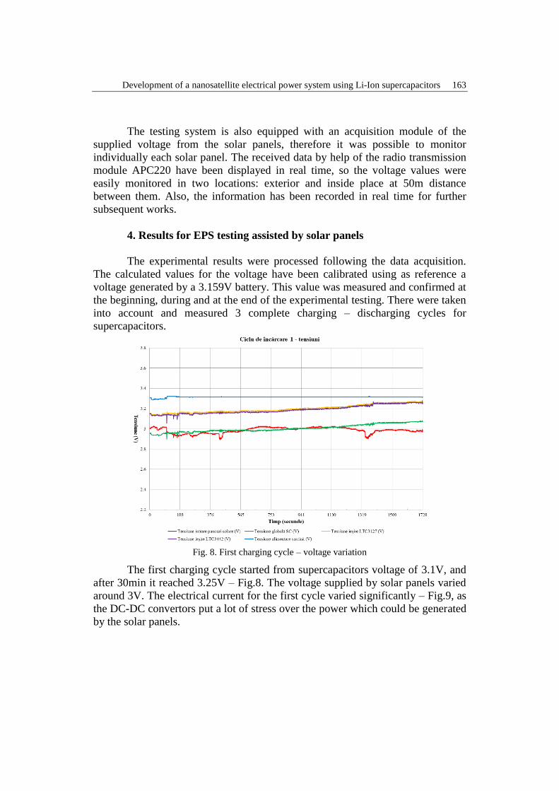
4. Results for EPS testing assisted by solar panels
The experimental results were processed following the data acquisition.
The calculated values for the voltage have been calibrated using as reference a
voltage generated by a 3.159V battery. This value was measured and confirmed at
the beginning, during and at the end of the experimental testing. There were taken
into account and measured 3 complete charging – discharging cycles for
supercapacitors.
Fig. 8. First charging cycle – voltage variation
The first charging cycle started from supercapacitors voltage of 3.1V, and
after 30min it reached 3.25V – Fig.8. The voltage supplied by solar panels varied
around 3V. The electrical current for the first cycle varied significantly – Fig.9, as
the DC-DC convertors put a lot of stress over the power which could be generated
by the solar panels.

164 Mihai Totu, Octavian Donţu, Eugenia Eftimie Totu
Fig. 9. First charging cycle – electrical current variation
The average value over 1A consumed from the solar panels power is closed to the
theoretical maximum of 1.22A which could be supplied by the 5 solar panels
under direct sun.
Fig.10. First cycle for functioning in dark conditions
As shown in Fig.10 for the first functioning cycle in dark conditions it was
recorded a system functioning for 16min without using solar energy. Considering

Development of a nanosatellite electrical power system using Li-Ion supercapacitors 165
a double number of supercapacitors for a final application, the circuits and
consumption optimization it was possible to prove the viability of the proposed
EPS system.
During the second charging cycle, starting the supercapacitors charging
from the minimum voltage, 2.2V, to 3.1V after 52min of solar charging. The
output voltage variations were higher than those from the first charging cycle, the
input voltage also presenting important fluctuations. Similar to the voltage
behavior, during the second charging cycle, the input current presented high
fluctuations which were reflected in an important variation of the output currents
for charging the supercapacitors. For the second discharging cycle it was
simulated a dark period of 7 min and 15 sec. During this period, the
supercapacitors’ voltage decreased from 2.75V to 2.25V while they were
supplying continuously an average current of 0.5A to the testing circuit. The
supply voltage at the load was constant at 3.3V.
For the third charging cycle, the average supplied voltage by the solar
panels was over 3V, and at the final of the charging cycle the supercapacitors’
voltage from 2.25V reached 2.9V. During the third charging cycle the current
varied constantly around 1A over the entire test. Towards the end of the 54min of
cycle time, the current presented a bit lower variations, directly correlated with a
lower variation of the output voltages for supercapacitors charging.
The last cycle for EPS power supply using only supercapacitors during the
dark period put in evidence that for 500s the supercapacitors’ voltage decreased
linear from 2.9 V to 2.3V while the circuit was supplying a 0.55A current. The
output voltage of the DC-DC convertor was 3.3V having a ripple current lower
than in the first two cycles.
5. Results for EPS testing in ideal conditions
Testing the EPS for general ideal efficiency was done using several
multimeters and oscilloscopes. The power was constant supplied using a constant
power source. There were measured the efficiency and capabilities of the 6
implemented modules. The efficiency for the supercapacitor circuit charger were
measured between 86 and 96% efficiency. Considering the LTC3127 manufacture
specifications, the DC-DC integrated circuit convertor used in this application, we
can consider the implementation almost ideal. The efficiency graph was drawn in
Fig. 11, based on extensive data measurement. To be noted, that the general
current input was limited to 0.28A, in this way keeping under control the main
total power consumption of the circuit. The general temperature rise was less than
5°C in all testing conditions, which shows a good thermal design for the PCB
passive cooling.

166 Mihai Totu, Octavian Donţu, Eugenia Eftimie Totu
Fig. 11. First supercapacitor charging circuit efficiency
The 5V convertors had a lower energy efficiency than the supercapacitors
chargers, although they could provide higher power conversion. In Fig. 12, it can
be observed the efficiency of the second DC-DC 5V convertor, developed using
LTC3421. The efficiency drop at higher power requirement could be created by
PCB design limitation in passive cooling. The ΔT increase in temperature of more
than 20°C in less than 5 minutes of 4.4W demand, shows that thermal dissipation
and management should be improved for the proposed design and PCB.
Fig. 12. Second 5V DC-DC convertor efficiency
The ideal efficiency of the 3.3V DC-DC converter is shown here for the
first 3.3V convertor, which converts power directly from the solar panels. This
circuit was developed using the LTC3112 as the central piece. As it can be seen,
for an output higher than 1A, so a power larger than 3.3W, the efficiency drops

Development of a nanosatellite electrical power system using Li-Ion supercapacitors 167
significantly, and the regulated output is lost at a voltage of 3.3V input,
consequently the converter cannot work in boosting mode any longer. Although, it
is difficult to believe that a nanosatellite would consume such a high power only
by using the 3.3V rail, this experiment proves that a very small power source to be
implemented in a satellite, capable of supplying power for any type of application.
Modifying different components of the implementation, such as the
inductor for the circuit, or the caps size, could improve the circuit efficiency at
specific functioning regimes, though differences from the drawn graphic show in
Fig. 13 will not be higher than 10% for the high load cases.
Fig. 13. First 3.3V DC-DC converter efficiency
6. Conclusions
According to the performed experiments, the proposed EPS design using
supercapacitors (8) compactly placed on PCBs is a good option for powering a
nanosatellite. The design did not imply any MPPT or other active power
management, and through several optimizations, this solution could be
implemented as working solution for CubeSats and other type of nanosatellites.
Mounting the supercapacitors on a single PCB or on two PCBs could be done
according to the application requirements. Our experimental data proved that it is
feasible to develop a new EPS using supercapacitors as primary and only source
for the electrical power storage. The EPS developed proved that is possible to use
3.5W by the 3.3V rail, 4.4W by the 5V rail, and twice 1.3W for supercapacitors
charging, for a total of 10.5W. Considering a good case of 5.5W power generated
by a 1U CubeSat solar panels (in case we use good quality expensive solar
panels), the power supply will never be overloaded, and together with the
redundancy implemented, it offers a complete solution that could be implemented
directly in a CubeSat nanosatellite structure.

168 Mihai Totu, Octavian Donţu, Eugenia Eftimie Totu
Acknowledgements
The work has been funded by the Sectoral Operational Programme Human
Resources Development 2007-2013 of the Ministry of European Funds through
the Financial Agreement POSDRU/159/1.5/S/137070.
R E F E R E N C E S
[1] Muhammad Alkali, Mohamed Y. Edries, Arifur R. Khan, Hirokazu Masui and Mengu Cho,
„Design Considerations and Ground Testing of Electric Double-Layer Capacitors as Energy
Storage Components for Nanosatellites”, Journal of Small Satellites, vol. 4, No. 2, 2015, pp.
387–405
[2] N.S. Fatemi, H.E. Pollard, H.Q. Hou, P.R. Sharps, „Solar array trades between very high-
efficiency multi-junction and Si space solar cells”, Photovoltaic Specialists Conference,
2000, Conference Record of the Twenty-Eighth IEEE
[3] Hans S. Rauschenbach, „Solar Cell Array Design Handbook: The Principles and Technology
of Photovoltaic Energy Conversion”, Ed. Springer, New York, 1980, ISBN: 978-94-011-
7917-1
[4] J.G. Llorente, D.R. Duarte, S.S. Sanjuan, Andres Rambal-Vecino, „Improving the Efficiency of
3U CubeSat EPS bySelecting Operating Conditions for Power Converters”, IEEE Aerospace
Conference Proceedings, Big Sky, Montana, USA, Mar. 2015
[5] Totu, Mihai, „An innovative Cubesat power system”, ICMERA 2013, Bucharest, 25 Oct. 2013
[6] Mohammed Chessab Mahdi, Adnan Falh Hassan, Jaafer Sadiq Jaafer, “New deployable solar
panel array for 1U nanosatellitrs”, ARPN Journal of Engineering and Applied Sciences, vol.
9, no. 11, Nov.2014, pp 2322-2326
[7] *** APC220 Radio Data Module: www.robotshop.com/media/files/PDF/dfrobot-apc220-
manual.pdf
[8] E. Totu, E. Segal, N. Luca, „On the texture of electroless copper films", Revue Roumanie de
Chimie, vol.40, 1995, pp. 859-866