Embed Size (px)
Citation preview
Development of a Nanosatellite Software Defined Radio Communication System
3rd February 2016
NATASHA GADKARI Department of Earth and Space Science
Lassonde School of Engineering York University
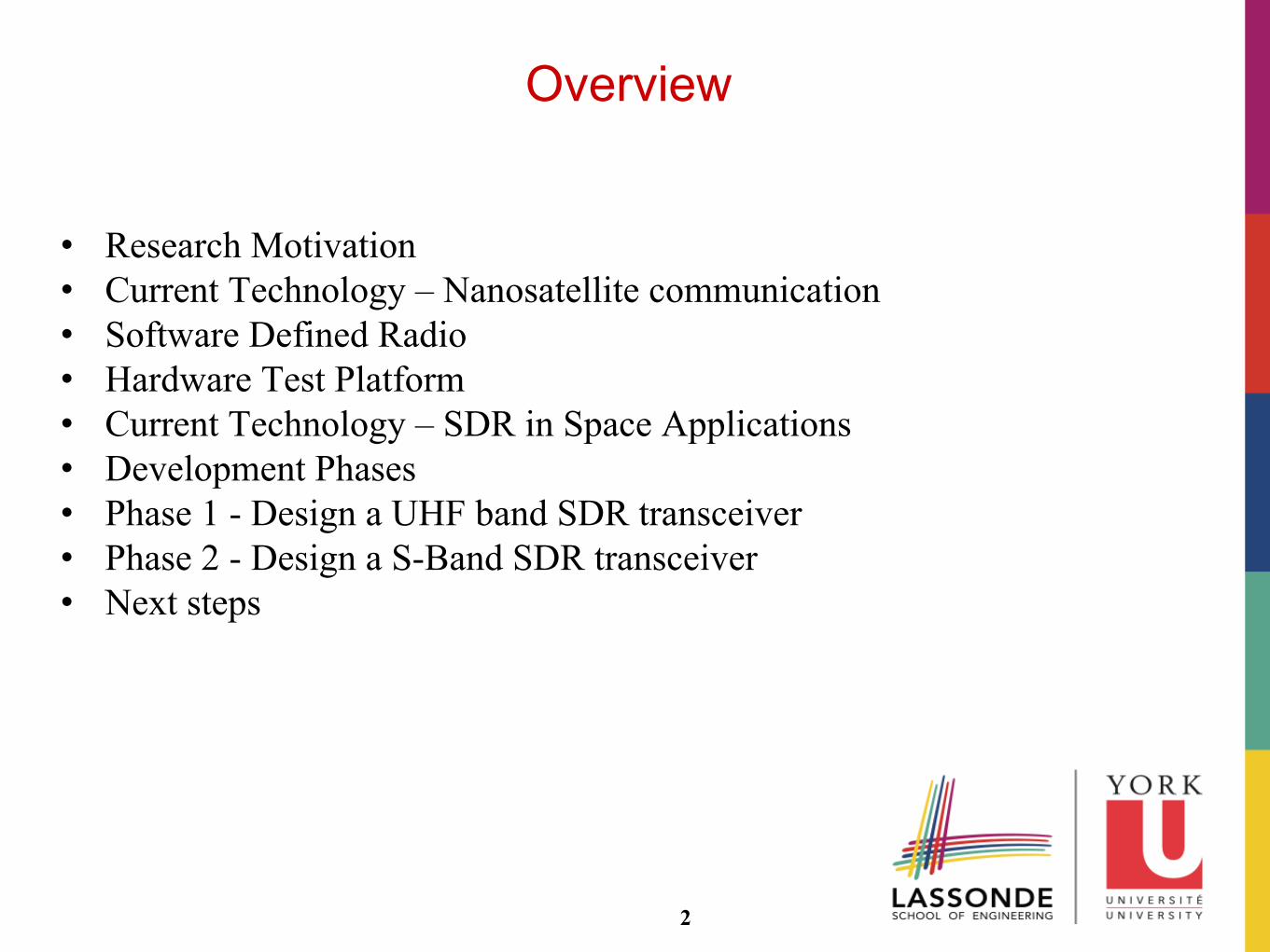
Overview
• Research Motivation • Current Technology – Nanosatellite communication • Software Defined Radio • Hardware Test Platform • Current Technology – SDR in Space Applications • Development Phases • Phase 1 - Design a UHF band SDR transceiver • Phase 2 - Design a S-Band SDR transceiver • Next steps
2
Research Motivation
Functional Needs
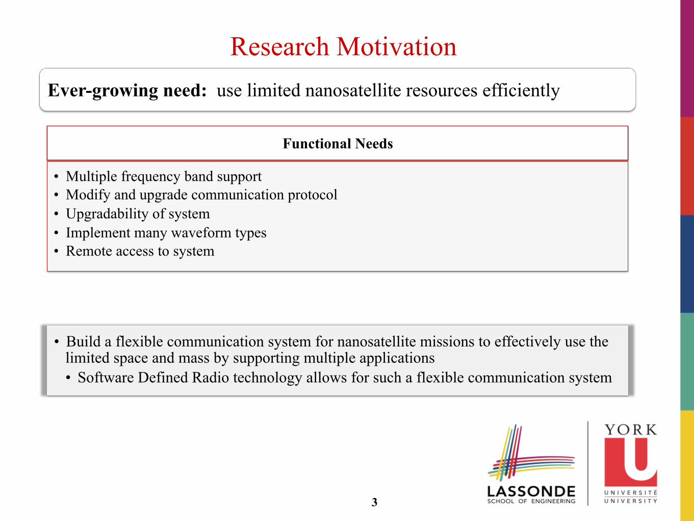
• Multiple frequency band support • Modify and upgrade communication protocol • Upgradability of system • Implement many waveform types • Remote access to system
3
Ever-growing need: use limited nanosatellite resources efficiently
• Build a flexible communication system for nanosatellite missions to effectively use the limited space and mass by supporting multiple applications • Software Defined Radio technology allows for such a flexible communication system
Current Technology - Nanosatellite Communication
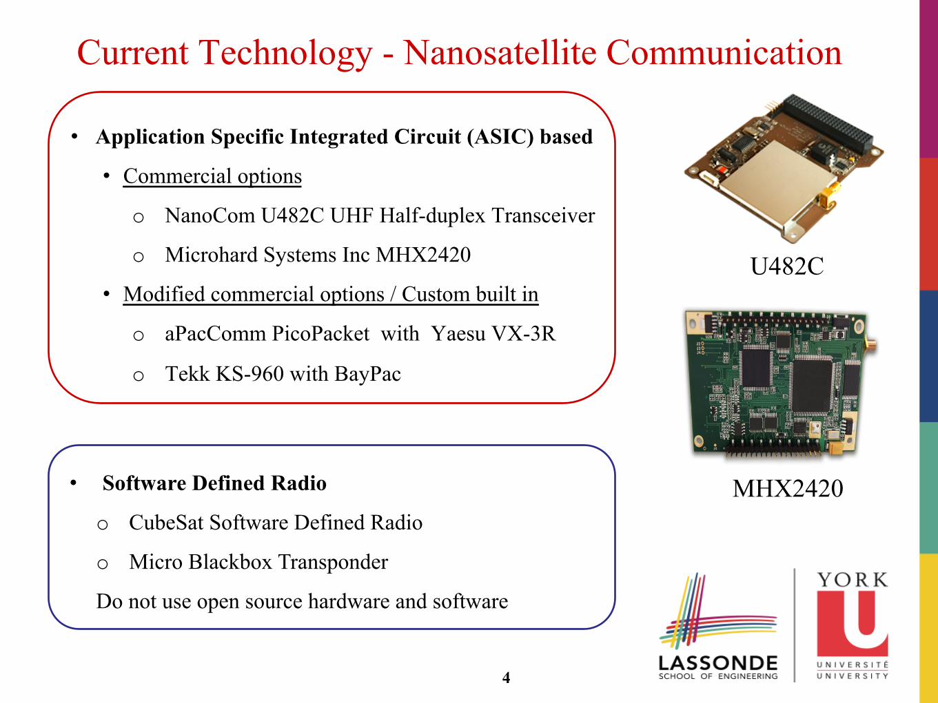
• Application Specific Integrated Circuit (ASIC) based
• Commercial options
o NanoCom U482C UHF Half-duplex Transceiver
o Microhard Systems Inc MHX2420
• Modified commercial options / Custom built in
o aPacComm PicoPacket with Yaesu VX-3R
o Tekk KS-960 with BayPac
U482C
MHX2420
4
• Software Defined Radio
o CubeSat Software Defined Radio
o Micro Blackbox Transponder
Do not use open source hardware and software
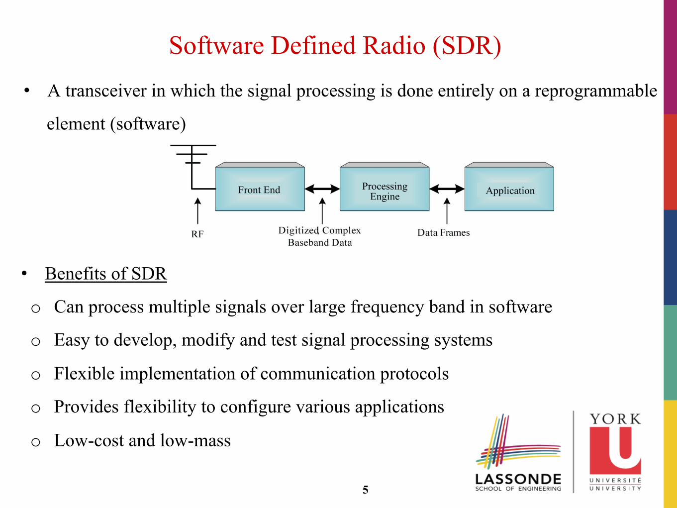
Software Defined Radio (SDR) • A transceiver in which the signal processing is done entirely on a reprogrammable
element (software)
5
• Benefits of SDR
o Can process multiple signals over large frequency band in software
o Easy to develop, modify and test signal processing systems
o Flexible implementation of communication protocols
o Provides flexibility to configure various applications
o Low-cost and low-mass
Hardware Test Platform
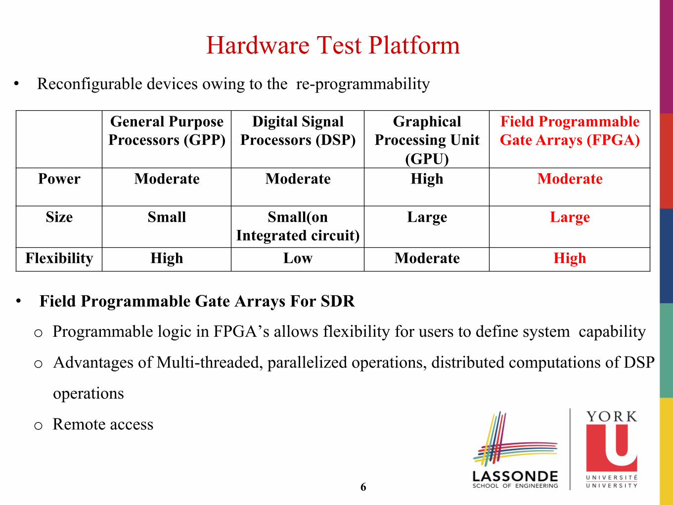
• Field Programmable Gate Arrays For SDR
o Programmable logic in FPGA’s allows flexibility for users to define system capability
o Advantages of Multi-threaded, parallelized operations, distributed computations of DSP
operations
o Remote access
General Purpose Processors (GPP)
Digital Signal Processors (DSP)
Graphical Processing Unit
(GPU)
Field Programmable Gate Arrays (FPGA)
Power Moderate
Moderate High Moderate
Size Small Small(on Integrated circuit)
Large Large
Flexibility High Low Moderate High
6
• Reconfigurable devices owing to the re-programmability
Current Technology - SDR in Space Applications
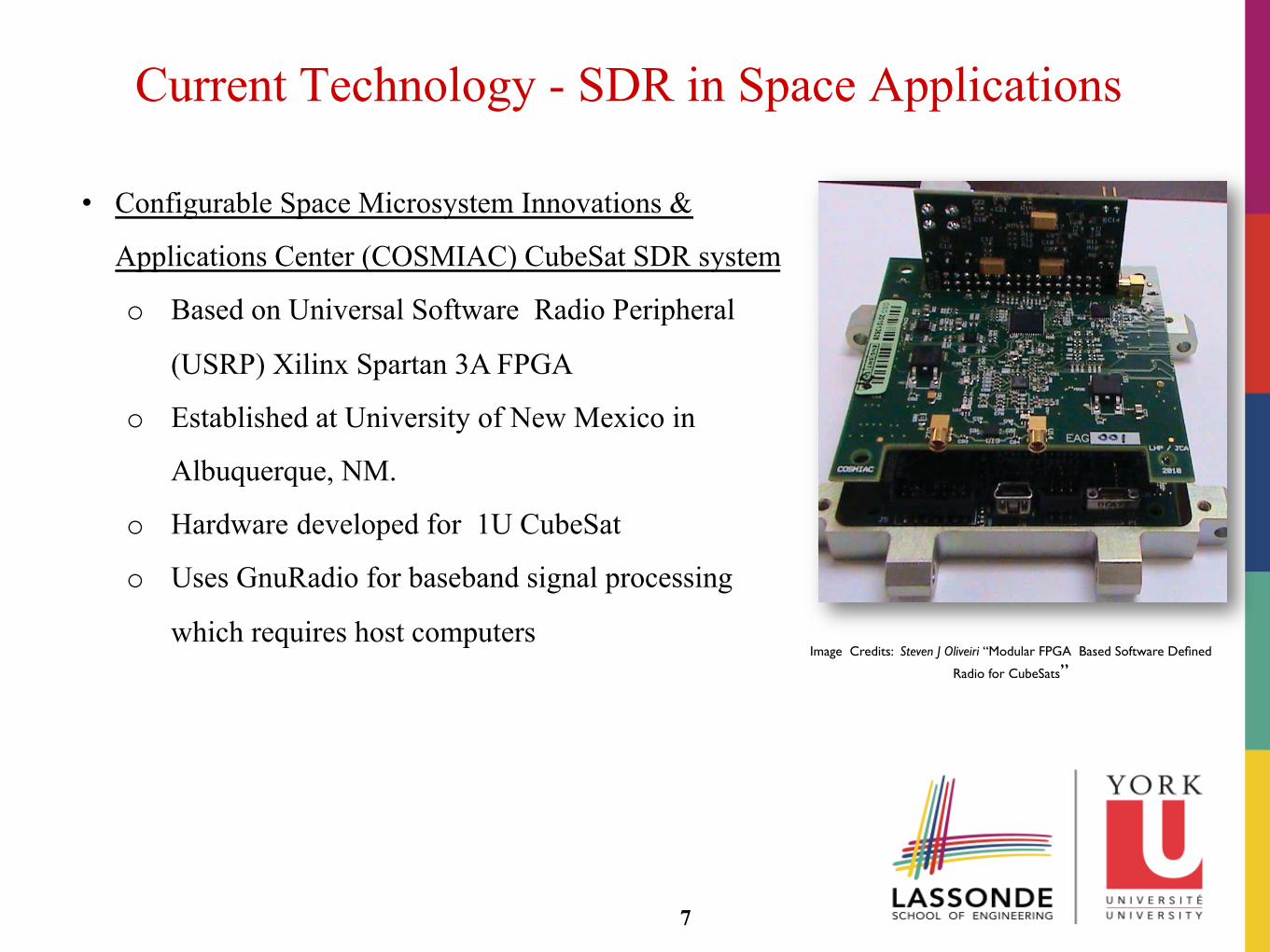
• Configurable Space Microsystem Innovations &
Applications Center (COSMIAC) CubeSat SDR system
o Based on Universal Software Radio Peripheral
(USRP) Xilinx Spartan 3A FPGA
o Established at University of New Mexico in
Albuquerque, NM.
o Hardware developed for 1U CubeSat
o Uses GnuRadio for baseband signal processing
which requires host computers
Image Credits: Steven J Oliveiri “Modular FPGA Based Software Defined
Radio for CubeSats”
7
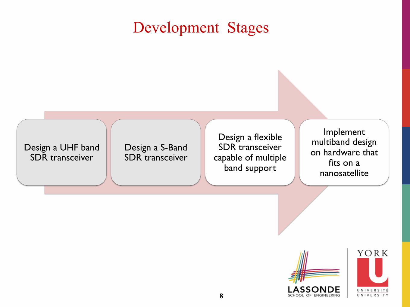
Development Stages
Design a UHF band SDR transceiver
Design a S-Band SDR transceiver
Design a flexible SDR transceiver
capable of multiple band support
Implement multiband design on hardware that
fits on a nanosatellite
8
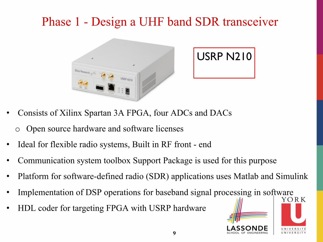
Phase 1 - Design a UHF band SDR transceiver
• Consists of Xilinx Spartan 3A FPGA, four ADCs and DACs
o Open source hardware and software licenses
• Ideal for flexible radio systems, Built in RF front - end
• Communication system toolbox Support Package is used for this purpose
• Platform for software-defined radio (SDR) applications uses Matlab and Simulink
• Implementation of DSP operations for baseband signal processing in software
• HDL coder for targeting FPGA with USRP hardware
9
USRP N210
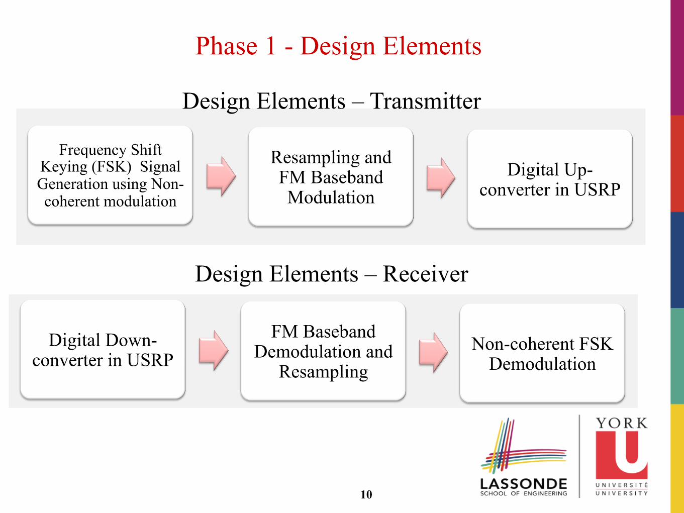
Phase 1 - Design Elements
Frequency Shift Keying (FSK) Signal Generation using Non-coherent modulation
Resampling and FM Baseband Modulation
Digital Up-converter in USRP
10
Digital Down-converter in USRP
FM Baseband Demodulation and
Resampling Non-coherent FSK
Demodulation
Design Elements – Transmitter
Design Elements – Receiver
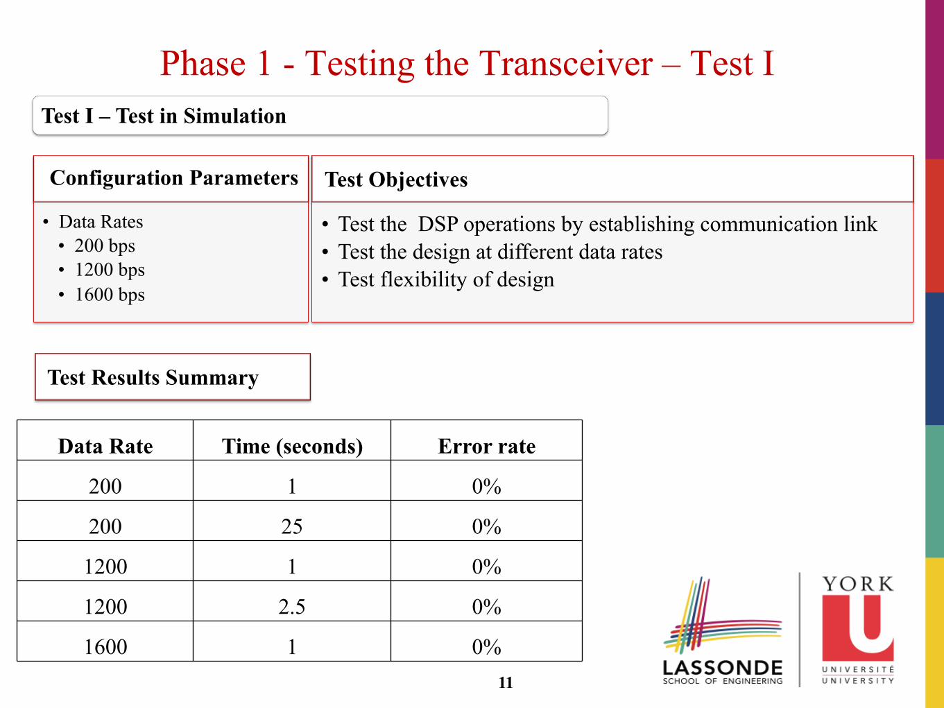
Phase 1 - Testing the Transceiver – Test I
11
Test Objectives
• Test the DSP operations by establishing communication link • Test the design at different data rates • Test flexibility of design
Configuration Parameters
• Data Rates • 200 bps • 1200 bps • 1600 bps
Test I – Test in Simulation
Data Rate Time (seconds) Error rate
200 1 0%
200 25 0%
1200 1 0%
1200 2.5 0%
1600 1 0%
Test Results Summary
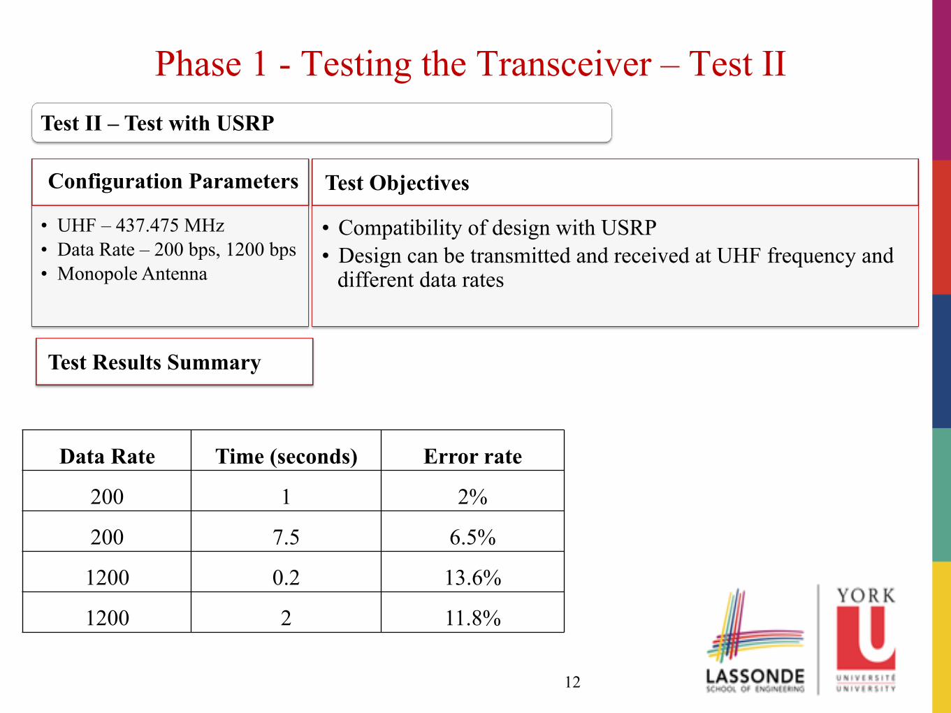
Phase 1 - Testing the Transceiver – Test II
12
Test Objectives
• Compatibility of design with USRP • Design can be transmitted and received at UHF frequency and
different data rates
Configuration Parameters
• UHF – 437.475 MHz • Data Rate – 200 bps, 1200 bps • Monopole Antenna
Test II – Test with USRP
Test Results Summary
Data Rate Time (seconds) Error rate
200 1 2%
200 7.5 6.5%
1200 0.2 13.6%
1200 2 11.8%
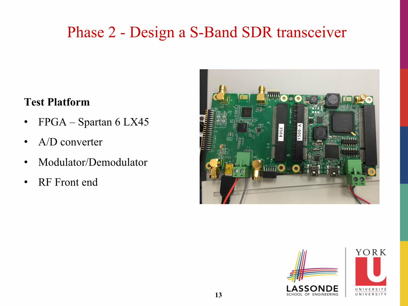
Test Platform
• FPGA – Spartan 6 LX45
• A/D converter
• Modulator/Demodulator
• RF Front end
13
Phase 2 - Design a S-Band SDR transceiver
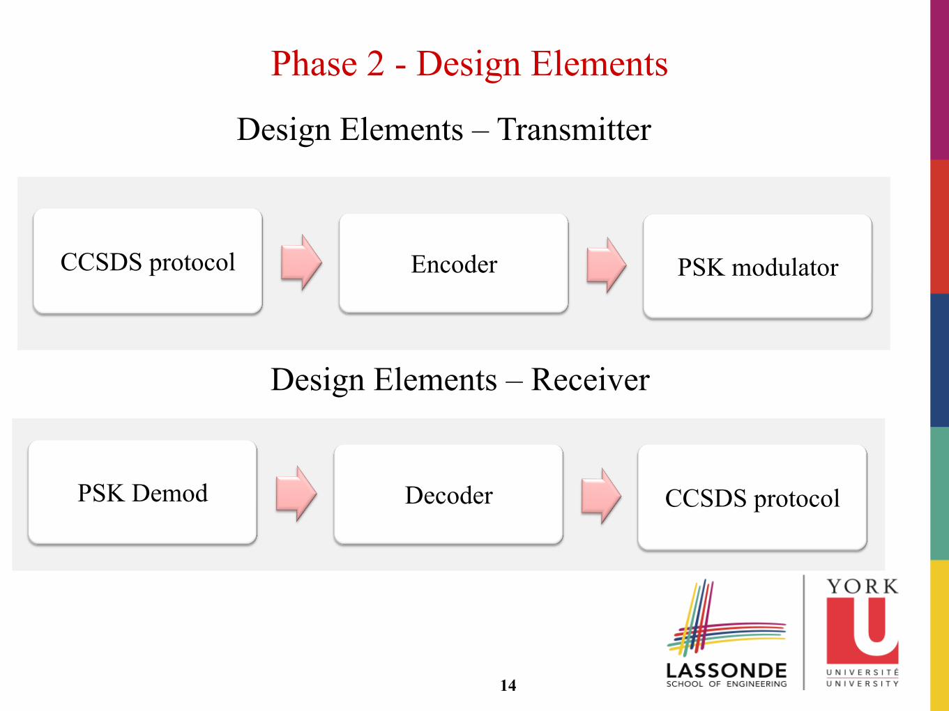
Phase 2 - Design Elements
14
CCSDS protocol Encoder PSK modulator
PSK Demod Decoder CCSDS protocol
Design Elements – Transmitter
Design Elements – Receiver
Next Steps
• Performance Improvement
o Transmitter-Receiver Synchronization for phase and timing recovery
o Implement error detection and correction techniques
• Design a flexible SDR transceiver capable of multiple band support
• Space Ready Communication System
o Modular standalone system
o Protocols and Space Environment Testing
15

This research is sponsored by:
16