Embed Size (px)
Citation preview
Development of a Damage Tolerant Truss based Composite Empennage Box
D Thulasi Durai, S R Viswamurthy, M Vinoth, Balasubramaniam, M Mohan Kumar and G N Dayananda
CSIR – National Aerospace Laboratories, Bengaluru, Karnataka 560017
Truss structures are widely used for the support of structural loads in applications where
minimum mass solutions are desired. Ideally these truss structure are made out of bars hinged
at the ends to transfer axial forces and moments. Truss structures provide high stiffness and
strength to weight ratio. In this study, this concept is considered towards the realization of a
truss based empennage of an aircraft. A three dimensional composite truss box is designed to
replace a conventional empennage interspar box without sacrificing stiffness and strength.
Several co-cured truss elements were fabricated. Simple tests conducted on these truss elements
indicate that one-to-one stiffness matching can be achieved between conventional and truss-
based structure. However, further design changes are needed to match their specific strength.
Weight savings of about 15% is expected through the use of truss based design concepts.
I. Introduction
Composite aircraft structural components such as empennage are nowadays mostly made of typical
skin- rib- stiffener constructions where the ribs and spars are of full depth. The mechanical properties of
composites are not fully exploited in these type of construction. In view of this it is very necessary to examine
new structural concepts which not only exploit the properties of composites better but also built in damage
tolerant features into the aircraft structure. This paper reports in details the design approach, analysis and
fabrication methods of a conventional box and an equivalent truss box of a typical civil aircraft. Experiments
were conducted to make one-to-one comparison between conventional and truss spar segments of the
empennage box. Several promising fabrication techniques are studied to find the optimal way of fabricating
aerospace quality truss based structural joints. A typical empennage box is taken as a numerical case study for
reduction in structural weight by replacing conventional spar and ribs with truss concepts. Skin, spars and
stringers are the main loading carrying members in the empennage box, while the ribs contribute only a little to
the overall stiffness of the empennage box.

Truss based structures provide opportunity to minimize weight by transferring loads effectively with in the
structure. In particular, they present an attractive option for structural elements such as ribs and spars which are
primarily designed to carry compressive and shear loads. If truss elements are used instead of a conventional
web in a spar, the shear load acting on the spar can be effectively diffused as axial loads on the truss elements.
Intuitively, this appears to be a more effective and efficient approach to carry the shear loads instead of a full
web on a conventional segment
Krog et al [1], conducted topology optimization of the A380 wing box to reduce rib weight. Ref. [2]
Sierakowski et al explains the need for damage tolerant design in composites compared to metals. Two major
criteria in selecting a damage tolerant design are: (a) Identification of the most severe and common form of
loading event, which results in damage that is structurally unacceptable, and (b) Identification of the resulting
failure mode associated with that damage which leads to good damage tolerant design. Ozden et al [3] carried
out integrated testing and analytical studies on damage tolerance of Graphite/epoxy composite tubes under
compressive loading. Swanson et al [4] conducted experimental studies and developed mathematical models of
triaxial composite tubes under two dimensional loading. The braided material shows somewhat reduction in
strength in axial direction. Analysis of the microstructure indicates that stiffness variations in the transverse
direction occur, because of the discrete axial yarns. These stiffness variations are believed to cause strain
concentrations that contribute to the low braid failure strains. Ayranci et al [5] studied the advantages and
disadvantages of 2D braided technology over stiffness and manufacturing process. Currently, several
researchers are studying composite truss joints which form an important part in such structures, and their load
transfer capacity and efficiency.
Braided composites are capable of handling shear and torsional loads effectively. Braided preform cured
with matrix system either by Resin Transfer Molding (RTM) method or by prepreg technology can be used as
load carrying members. They offer increased transverse moduli, transverse strength, damage tolerance,
dimensional stability and near net shape manufacturing capabilities. Damage tolerance is a consequence of the
locking mechanism between the intertwined fibers of the braided architecture that prevents or limits yarn
delimitations.
II. Composite Empennage Box A typical civil aircraft empennage inter spar section box of size (2000mm* 1500mm * 350mm) made out of
CFRP composites was considered in this study towards replacement of conventional spar and ribs with truss
elements. Empennage is an aviation term used to describe the tail section of an aircraft. The inter spar box is the
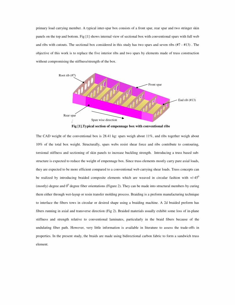
primary load carrying member. A typical inter-spar box consists of a front spar, rear spar and two stringer skin
panels on the top and bottom. Fig [1] shows internal view of sectional box with conventional spars with full web
and ribs with cutouts. The sectional box considered in this study has two spars and seven ribs (#7 - #13) . The
objective of this work is to replace the five interior ribs and two spars by elements made of truss construction
without compromising the stiffness/strength of the box.
Fig [1].Typical section of empennage box with conventional ribs
The CAD weight of the conventional box is 28.41 kg: spars weigh about 11%, and ribs together weigh about
10% of the total box weight. Structurally, spars webs resist shear force and ribs contribute to contouring,
torsional stiffness and sectioning of skin panels to increase buckling strength. Introducing a truss based sub-
structure is expected to reduce the weight of empennage box. Since truss elements mostly carry pure axial loads,
they are expected to be more efficient compared to a conventional web carrying shear loads. Truss concepts can
be realized by introducing braided composite elements which are weaved in circular fashion with +/-450
(mostly) degree and 00 degree fiber orientations (Figure 2). They can be made into structural members by curing
them either through wet-layup or resin transfer molding process. Braiding is a preform manufacturing technique
to interlace the fibers tows in circular or desired shape using a braiding machine. A 2d braided preform has
fibers running in axial and transverse direction (Fig 2). Braided materials usually exhibit some loss of in-plane
stiffness and strength relative to conventional laminates, particularly in the braid fibers because of the
undulating fiber path. However, very little information is available in literature to assess the trade-offs in
properties. In the present study, the braids are made using bidirectional carbon fabric to form a sandwich truss
element.
Root rib (#7)
Front spar
Rear spar
End rib (#13)
Span wise direction
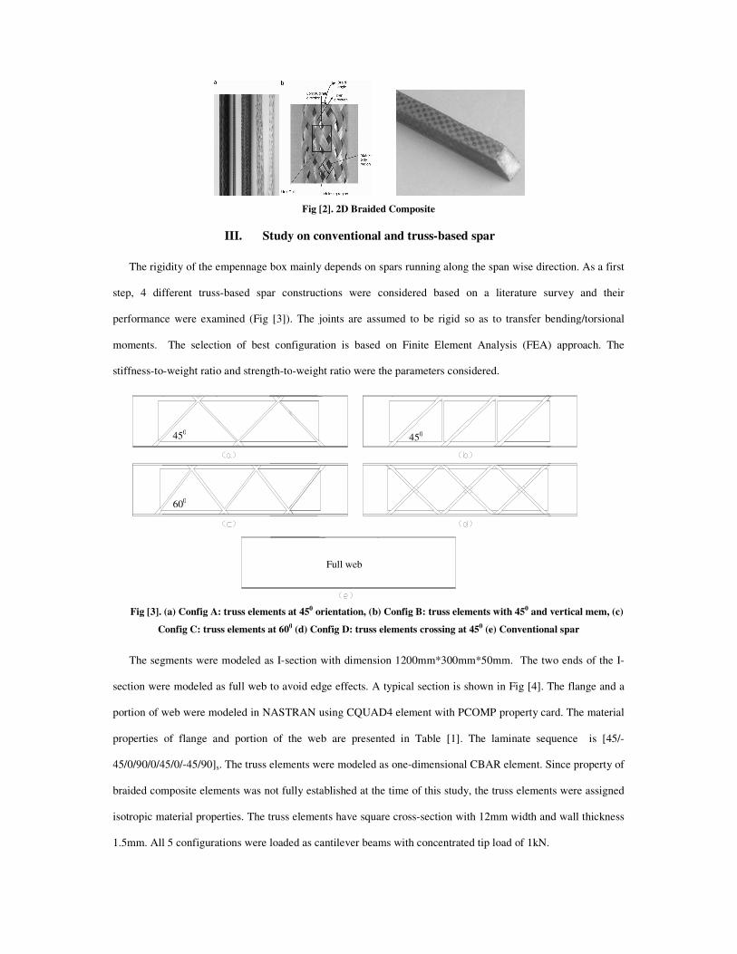
III. Study o
The rigidity of the empennage box mainly depends on spars running along
step, 4 different truss-based spar constructions
performance were examined (Fig [3]). The joints are
moments. The selection of best configuration is based on Finite Element Analysis (FEA) approach. The
stiffness-to-weight ratio and strength-to
Fig [3]. (a) Config A: truss elements at 45
Config C: truss elements at 600
The segments were modeled as I-section with dimension 1200mm*300mm*50mm. The two ends of the I
section were modeled as full web to avoid edge effects. A typical section is shown in Fig [4]. The flange
portion of web were modeled in NASTRAN
properties of flange and portion of the web are
45/0/90/0/45/0/-45/90]s. The truss elements were
braided composite elements was not fully established at the time of this study, the truss elements were
isotropic material properties. The truss elements have s
1.5mm. All 5 configurations were loaded as cantilever beams with concentrated tip load of 1kN.
450
600
Fig [2]. 2D Braided Composite
tudy on conventional and truss-based spar
The rigidity of the empennage box mainly depends on spars running along the span wise direction.
spar constructions were considered based on a literature survey
. The joints are assumed to be rigid so as to transfer bending/torsional
configuration is based on Finite Element Analysis (FEA) approach. The
to-weight ratio were the parameters considered.
at 450 orientation, (b) Config B: truss elements with 450 and vertical mem0 (d) Config D: truss elements crossing at 450 (e) Conventional spar
section with dimension 1200mm*300mm*50mm. The two ends of the I
section were modeled as full web to avoid edge effects. A typical section is shown in Fig [4]. The flange
in NASTRAN using CQUAD4 element with PCOMP property card
of flange and portion of the web are presented in Table [1]. The laminate sequence
. The truss elements were modeled as one-dimensional CBAR element. Since
not fully established at the time of this study, the truss elements were
The truss elements have square cross-section with 12mm width and wall thickness
All 5 configurations were loaded as cantilever beams with concentrated tip load of 1kN.
450
Full web
span wise direction. As a first
survey and their
to transfer bending/torsional
configuration is based on Finite Element Analysis (FEA) approach. The
and vertical mem, (c)
(e) Conventional spar
section with dimension 1200mm*300mm*50mm. The two ends of the I-
section were modeled as full web to avoid edge effects. A typical section is shown in Fig [4]. The flange and a
property card. The material
laminate sequence is [45/-
Since property of
not fully established at the time of this study, the truss elements were assigned
12mm width and wall thickness
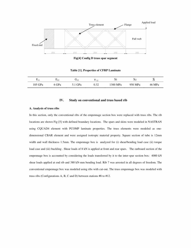
Fig[4] Config D truss spar segment
Table [1]. Properties of CFRP Laminate
E11 E22 G12 � 12 Xt Xc S
105 GPa 6 GPa 5.1 GPa 0.32 1300 MPa 950 MPa 46 MPa
IV. Study on conventional and truss based rib
A. Analysis of truss ribs
In this section, only the conventional ribs of the empennage section box were replaced with truss ribs. The rib
locations are shown Fig [5] with defined boundary locations. The spars and skins were modeled in NASTRAN
using CQUAD4 element with PCOMP laminate properties. The truss elements were modeled as one-
dimensional CBAR element and were assigned isotropic material property. Square section of tube is 12mm
width and wall thickness 1.5mm. The empennage box is analyzed for (i) shear/bending load case (ii) torque
load case and (iii) buckling . Shear loads of 8 kN is applied at front and rear spars. The outboard section of the
empennage box is accounted by considering the loads transferred by it to the inter-spar section box: 4000 kN
shear loads applied at end rib and 380 kN-mm bending load. Rib 7 was arrested in all degrees of freedom. The
conventional empennage box was modeled using ribs with cut-out. The truss empennage box was modeled with
truss ribs (Configurations A, B, C and D) between stations #8 to #12.
Fixed end
Applied load
Full web
Flange Truss element

Fig[5]. FE model of empennage box with rib (index) location
B. Analysis of truss box
In this section, both the spars and ribs were replaced with truss configuration. To study the stiffness/strength
characteristics truss configuration; box level analysis is being carried out for config D with above said boundary
condition in section [A]. The modeled weight budgets of the configurations are shown in Table [2].
Table [2]. Weight budget of various sub components of sectional box
Sub parts Conventional Config Truss Config
Front and rear spar (Kg) 3.17 1.914
Truss ribs #8 to #12 (Kg) 3.02 2.02
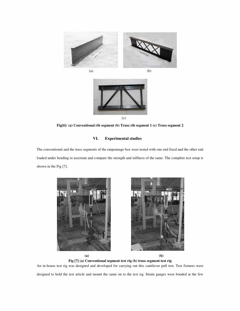
V. Fabrication of conventional/truss spar segment
A conventional/truss structural I-section segment was fabricated using hand layup technique
(1500mm*300mm*50mm) Fig[6]. The fabrication of truss segment is highly challenging. CFRP carbon UD/BD
fabric material use to fabricate the I-sections. The truss braids preform were sandwich between foam core to
retain its shape (12 mm diameter) and co-cured along with T-section. The fabricated segment shows the possible
way of curing one element, two element joints and three element joints. The moulds were made out of laminated
sheet of 25mm thick machined and carved to the required shape. Resin Transfer Molding (RTM) and Autoclave
molding using prepregs for fabrication are currently under progress. The conventional segment weighs about
2.56 Kg and truss spar segment weighs about 1.51 Kg.
#13
#7 #8
#9 #10
#11
#12
Arrested all DOF
Concentrated Bending load
Concentrated shear load
(a)
Fig[6]: (a) Conventional rib segment (b) Truss rib segment 1 (c) Truss segment 2
VI.
The conventional and the truss segments of the
loaded under bending to ascertain and compare the strength and stiffness of the same. The complete test setup is
shown in the Fig [7].
(a) Fig [7] (a) Conventional segment
An in-house test rig was designed and developed for carrying out this cantilever pull test. Test fixtures were
designed to hold the test article and mount the same on to the test rig. Strain gauges were bonded at the fe
(b)
(c)
Fig[6]: (a) Conventional rib segment (b) Truss rib segment 1 (c) Truss segment 2
VI. Experimental studies
The conventional and the truss segments of the empennage box were tested with one end fixed and the other end
loaded under bending to ascertain and compare the strength and stiffness of the same. The complete test setup is
(b) Fig [7] (a) Conventional segment test rig (b) truss segment test rig
house test rig was designed and developed for carrying out this cantilever pull test. Test fixtures were
designed to hold the test article and mount the same on to the test rig. Strain gauges were bonded at the fe
Fig[6]: (a) Conventional rib segment (b) Truss rib segment 1 (c) Truss segment 2
box were tested with one end fixed and the other end
loaded under bending to ascertain and compare the strength and stiffness of the same. The complete test setup is
house test rig was designed and developed for carrying out this cantilever pull test. Test fixtures were
designed to hold the test article and mount the same on to the test rig. Strain gauges were bonded at the few

critical locations especially at the flanges and web of the segment at its fixed. A lording fixture for applying the
load at the other free end was developed which in turn connects to an hydraulic actuator for the load application.
The strain response of the segments were monitored at the various loading steps till its failure .The tip
displacement of the cantilever segment was monitored using a displacement transducer at every load step till the
failure of the test specimen.
VII. Results and discussion
(a) Stiffness characteristic of truss segments is shown in Fig [8]. The analysis is being carried to match the
stiffness close to convectional full web spar. Comparatively Config D has maximum stiffness of 157.941 N/mm,
where Config A has least stiffness of 99.66 N/mm, other segment stands between these two values.
Fig[8]. Comparison of stiffness for different configurations of spars
(b) Conventional rib with cut-out web were replaced with truss structure. The analysis result of empennage box
is shown in Table [3]. The tip deflections of these configurations were close to conventional box. The first three
buckling modes were near the root due to edge effect were not considered for tabulation. Comparatively config
D has high buckling factor to conventional model but truss segment with 600 degree orientation (Config C) will
be an optimum selection in terms of weight and response to load. The response to twisting torque is about 0.30 at
rib#7 for all the configurations.
1000 2000 3000 4000 5000 6000 7000 8000 9000 100000
10
20
30
40
50
60
70
80
90
100
Load (N)
Def
lect
ion
(mm
)
Config AConfig BConfig CConfig DConfig E
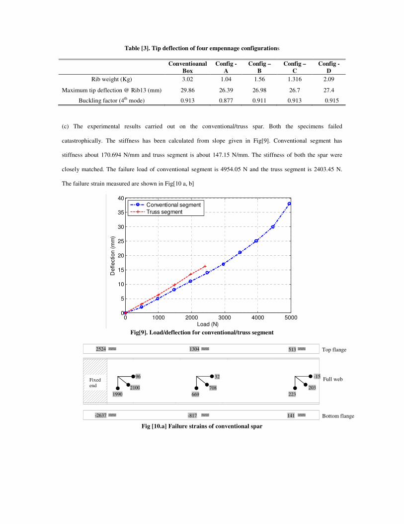
Table [3]. Tip deflection of four empennage configurations
Conventioanal Box
Config - A
Config – B
Config – C
Config - D
Rib weight (Kg) 3.02 1.04 1.56 1.316 2.09
Maximum tip deflection @ Rib13 (mm) 29.86 26.39 26.98 26.7 27.4
Buckling factor (4th mode) 0.913 0.877 0.911 0.913 0.915 (c) The experimental results carried out on the conventional/truss spar. Both the specimens failed
catastrophically. The stiffness has been calculated from slope given in Fig[9]. Conventional segment has
stiffness about 170.694 N/mm and truss segment is about 147.15 N/mm. The stiffness of both the spar were
closely matched. The failure load of conventional segment is 4954.05 N and the truss segment is 2403.45 N.
The failure strain measured are shown in Fig[10 a, b]
Fig[9]. Load/deflection for conventional/truss segment
Fig [10.a] Failure strains of conventional spar
0 1000 2000 3000 4000 50000
5
10
15
20
25
30
35
40
Load (N)
Def
lect
ion
(mm
)
Conventional segmentTruss segment
2524 1304 513
-2637 -817 141
Top flange
Full web
Bottom flange
Fixed end
-15
203 223
32
708 669
96
2100 1990
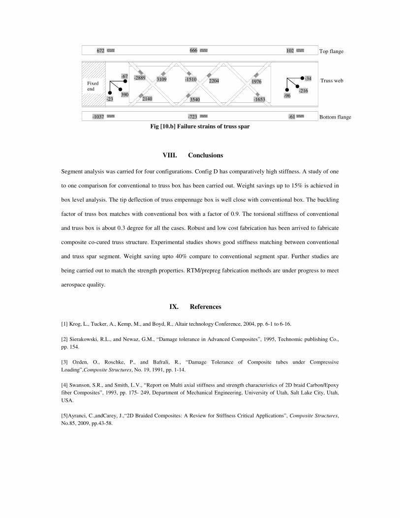
Fig [10.b] Failure strains of truss spar
VIII. Conclusions
Segment analysis was carried for four configurations. Config D has comparatively high stiffness. A study of one
to one comparison for conventional to truss box has been carried out. Weight savings up to 15% is achieved in
box level analysis. The tip deflection of truss empennage box is well close with conventional box. The buckling
factor of truss box matches with conventional box with a factor of 0.9. The torsional stiffness of conventional
and truss box is about 0.3 degree for all the cases. Robust and low cost fabrication has been arrived to fabricate
composite co-cured truss structure. Experimental studies shows good stiffness matching between conventional
and truss spar segment. Weight saving upto 40% compare to conventional segment spar. Further studies are
being carried out to match the strength properties. RTM/prepreg fabrication methods are under progress to meet
aerospace quality.
IX. References
[1] Krog, L., Tucker, A., Kemp, M., and Boyd, R., Altair technology Conference, 2004, pp. 6-1 to 6-16. [2] Sierakowski, R.L., and Newaz, G.M., “Damage tolerance in Advanced Composites”, 1995, Technomic publishing Co., pp. 154. [3] Ozden, O., Roschke, P., and Bafrali, R., “Damage Tolerance of Composite tubes under Compressive Loading”,Composite Structures, No. 19, 1991, pp. 1-14. [4] Swanson, S.R., and Smith, L.V., “Report on Multi axial stiffness and strength characteristics of 2D braid Carbon/Epoxy fiber Composites”, 1993, pp. 175- 249, Department of Mechanical Engineering, University of Utah, Salt Lake City, Utah, USA. [5]Ayranci, C.,andCarey, J.,“2D Braided Composites: A Review for Stiffness Critical Applications”, Composite Structures, No.85, 2009, pp.43-58.
-67 Fixed end
Top flange
Truss web
Bottom flange
672 666 102
-1037 -723 -61
-2889
2140
3109 -1510
3540
2204 1976
-1653 -96
-34
-216 390
-23