Embed Size (px)
Citation preview
INCAS BULLETIN, Volume 13, Issue 3/ 2021, pp. 149 – 164 (P) ISSN 2066-8201, (E) ISSN 2247-4528
Empennage sizing with the tail volume complemented with a method for dorsal fin layout
Dieter SCHOLZ*
*Corresponding authorAircraft Design and Systems Group (AERO),
Hamburg University of Applied Sciences, Berliner Tor 9, 20099 Hamburg, Germany,
[email protected] DOI: 10.13111/2066-8201.2021.13.3.13
Received: 14 June 2021/ Accepted: 25 August 2021/ Published: September 2021 Copyright © 2021. Published by INCAS. This is an “open access” article under the CC BY-NC-ND license (http://creativecommons.org/licenses/by-nc-nd/4.0/)
Abstract: Purpose: Provide good values for the tail volume coefficient and the lever arm as a percentage of the fuselage length. Provide a statistical method for dorsal fin layout. – Methodology: Based on an understanding of flight physics, the statistical correlation of real aircraft parameters is investigated. This is based on the firm conviction that high fidelity parameters for future aircraft need a check against parameters of existing successful aircraft. – Findings: Typical tail volume coefficients are between 0.5 and 1.0 for the horizontal tail and between 0.03 and 0.08 for the vertical tail depending on aircraft category. Empennage statistics have clear trends. The often weak correlation shows that aircraft design allows for sufficient designer's choice. Only a minority of aircraft feature a dorsal fin. Designers see it as an added surface rather than as part of the vertical tail. It is used to limit the hypothetical risk of vertical tail stall due to high sideslip angles. – Research Limitations: Results obtained from statistics are close to reality, but not a proof to fulfill requirements. – Practical Implications: Methods from the paper can be used for quick initial sizing of a vertical tail with or without dorsal fin or sizing of a horizontal tail. These results can also be used as good starting values for optimization tools in aircraft design. – Originality: Estimation of the tail lever arm is necessary for sizing with the tail volume coefficient, but had not been investigated to any detail. A method for the layout of dorsal fins was missing.
Key Words: aircraft, airplane, tail, tailplane, stabilizer, fin, THS, lever, moment, fuselage, wing
1. INTRODUCTION1.1 Fundamentals
Empennage (originally a French word) means “tail” and usually comprises of the horizontal and the vertical tail (see Fig. 1 and Fig. 2). The vertical tail may also be called fin. Conventional aircraft (“tail aft aircraft”) have the tail mounted on the aft fuselage. Common is also the T-tail (Fig. 5), where the horizontal tail is mounted on top of the vertical tail. Other tail configurations are the V-tail or the H-tail (named after their shape, when the aircraft is seen from the rear). Also unconventional aircraft and tail configurations exist (Chapter 4 in [1]). One such example is the canard configuration with the horizontal tail attached to the front of the fuselage.

Dieter SCHOLZ 150
INCAS BULLETIN, Volume 13, Issue 3/ 2021
Fig. 1 – Conventional empennage of a Boeing 747-200 with horizontal and vertical tail attached directly to the
fuselage [2]
Fig. 2 – Conventional empennage with horizontal tail and vertical tail. The tail consists of the larger stabilizer and the smaller elevator and rudder. Elevator and rudder can be in one piece or can be split into two or more parts as
on this Airbus A380 [3]
An empennage ensures trim, stability, and control (Chapter 9 in [1]). Dynamic and static stability is increased with larger tail surfaces. An aircraft can be trimmed for larger longitudinal shifts of the Center of Gravity (CG) if the horizontal tail is larger. Nevertheless, aim is to fulfill requirements with a tail as small as possible, because a small tail is lighter and has less wetted area and drag.
For static directional stability, an aft vertical tail ensures that the aircraft points into the airflow (“weathercock stability”) to avoid a sideslip angle. The rudder is for yaw trim and yaw control and produces a yawing moment (about the vertical axis). Yaw trim is necessary in an asymmetric engine out situation or for any other directional asymmetry e.g. due to propeller spiral slipstream.
The horizontal tail setting angle is often variable for trim and the surface may be called Trimmable Horizontal Stabilizer (THS). The THS produces a pitching moment (about the lateral axis) and is adjusted slowly to compensate changes in thrust setting, CG location, flap deflection, or landing gear position (extended or retracted). With a THS, the fast moving elevator is for pitch control only. In case of a fixed horizontal tail, the elevator is also responsible for pitch trim. For static longitudinal stability the aircraft experiences a nose up pitching moment with speed increase and a nose down pitching moment with speed decrease. This requires the horizontal tail to produce more or less of a downward force.

151 Empennage sizing using the tail volume complemented with a method for dorsal fin layout
INCAS BULLETIN, Volume 13, Issue 3/ 2021
The wing geometry – with wing vertical position, wing sweep, and wing dihedral – takes care of roll stability. The ailerons take care of roll trim. Together with the roll spoilers (as far as available) they take care of roll control and produce a rolling moment (about the longitudinal axis).
1.2 Aircraft design iterations
The design process of passenger aircraft has its distinct phases. The sequence of these phases is not unique and agreed. Different authors propose a slightly different sequence or leave the decision of the calculation sequence to the reader. Design parameters are strongly linked to one another. Every change of one value causes an alteration of some other value. In addition, the whole design process has an iterative nature. These are the steps in the aircraft design sequence proposed by [1], because this sequence tends to limit the number of iterations:
1. Definition of Requirements 2. Comparative Studies 3. Selection of an Aircraft Configuration 4. Selection of a Propulsion System 5. Preliminary Sizing 6. Cabin and Fuselage Design 7. Wing Design 8. Design for High Lift 9. Empennage Sizing Using the Tail Volume 10. Mass and Center of Gravity (CG) Estimation 11. Empennage Sizing from Stability and Control Requirements 12. Landing Gear Conceptual Design and Integration 13. Drag Estimation, Drag Polar, L/D 14. Check Aircraft Performance 15. Direct Operating Cost (DOC) Calculation and Design Evaluation 16. Presentation of Design Results (Cabin Cross Section, Cabin Layout, Three-View-
Drawing, List of Parameters), 3D Visualization of the Aircraft, Interfacing to other Tools
Step 9 “Empennage Sizing Using the Tail Volume” is the topic of this paper. The paper extends Chapter 9 of the Aircraft Design Lecture Notes [1].
The aircraft design sequence from Step 9, 10, 11, to 12 is quite iterative. Step 9 in the design sequence delivers the initial value of the surface area for the horizontal and vertical tail. The tail surface areas are required as input for Step 10 “Mass and CG Estimation” (Chapter 10 in [1]), because the mass of horizontal and vertical tail are estimated mainly from their surface area. Mass estimation is iterative in itself. Once the Center of Gravity (CG) is calculated from the mass and position of all major aircraft components, it may be necessary to shift the wing with respect to the fuselage in such a way that the CG is in a correct and favorable position to the wing. On a well balanced aircraft configuration (with engines under the wing), the wing is usually located such that the CG of the empty aircraft is positioned on the 25%-point on the Mean Aerodynamic Chord (MAC) of the wing. Only once the wing is in place, the lever arm of the tail can be determined. The tail has to produce a moment (force times lever arm). The larger the surface area, the larger a possible aerodynamic force. Hence, the required force and required surface area depends on the lever arm. The larger the lever arm, the smaller the required surface area. Here we see the iterative nature of the design process between Step 9 and Step 10. Step 11 (Chapter 11 in [1]) applies flight mechanics to calculate required tail surface areas from stability and control requirements for horizontal and
Dieter SCHOLZ 152
INCAS BULLETIN, Volume 13, Issue 3/ 2021
1. Requirements
2. Comparative Studies
3. Aircraft Configuration
4. Propulsion System
5. Preliminary Sizing
6. Cabin and Fuselage
7. Wing, Aileron, Spoiler
8. High Lift System
9. Empennage, Elevator, Rudder
10. Mass & Center of Gravity
11. Stability & Control
12. Landing Gear
13. Polar, L/D, Take-Off Mass
14. Aircraft Performance
15. Operating Costs / DOC
16. Three-View Drawing
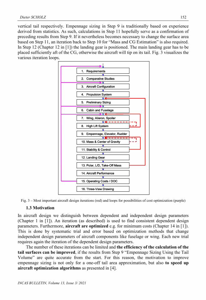
vertical tail respectively. Empennage sizing in Step 9 is traditionally based on experience derived from statistics. As such, calculations in Step 11 hopefully serve as a confirmation of preceding results from Step 9. If it nevertheless becomes necessary to change the surface area based on Step 11, an iteration back to Step 10 for “Mass and CG Estimation” is also required. In Step 12 (Chapter 12 in [1]) the landing gear is positioned. The main landing gear has to be placed sufficiently aft of the CG, otherwise the aircraft will tip on its tail. Fig. 3 visualizes the various iteration loops.
Fig. 3 – Most important aircraft design iterations (red) and loops for possibilities of cost optimization (purple)
1.3 Motivation
In aircraft design we distinguish between dependent and independent design parameters (Chapter 1 in [1]). An iteration (as described) is used to find consistent dependent design parameters. Furthermore, aircraft are optimized e.g. for minimum costs (Chapter 14 in [1]). This is done by systematic trial and error based on optimization methods that change independent design parameters of aircraft components like fuselage or wing. Each new trial requires again the iteration of the dependent design parameters.
The number of these iterations can be limited and the efficiency of the calculation of the tail surfaces can be improved, if the results from Step 9 “Empennage Sizing Using the Tail Volume” are quite accurate from the start. For this reason, the motivation to improve empennage sizing is not only for a one-off tail area approximation, but also to speed up aircraft optimization algorithms as presented in [4].
153 Empennage sizing using the tail volume complemented with a method for dorsal fin layout
INCAS BULLETIN, Volume 13, Issue 3/ 2021
1.4 Definitions
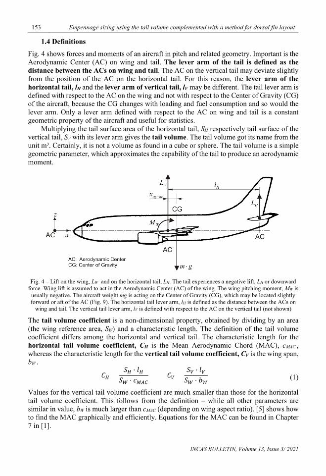
Fig. 4 shows forces and moments of an aircraft in pitch and related geometry. Important is the Aerodynamic Center (AC) on wing and tail. The lever arm of the tail is defined as the distance between the ACs on wing and tail. The AC on the vertical tail may deviate slightly from the position of the AC on the horizontal tail. For this reason, the lever arm of the horizontal tail, lH and the lever arm of vertical tail, lV may be different. The tail lever arm is defined with respect to the AC on the wing and not with respect to the Center of Gravity (CG) of the aircraft, because the CG changes with loading and fuel consumption and so would the lever arm. Only a lever arm defined with respect to the AC on wing and tail is a constant geometric property of the aircraft and useful for statistics.
Multiplying the tail surface area of the horizontal tail, SH respectively tail surface of the vertical tail, SV with its lever arm gives the tail volume. The tail volume got its name from the unit m³. Certainly, it is not a volume as found in a cube or sphere. The tail volume is a simple geometric parameter, which approximates the capability of the tail to produce an aerodynamic moment.
Fig. 4 – Lift on the wing, LW and on the horizontal tail, LH. The tail experiences a negative lift, LH or downward
force. Wing lift is assumed to act in the Aerodynamic Center (AC) of the wing. The wing pitching moment, MW is usually negative. The aircraft weight mg is acting on the Center of Gravity (CG), which may be located slightly forward or aft of the AC (Fig. 9). The horizontal tail lever arm, lH is defined as the distance between the ACs on
wing and tail. The vertical tail lever arm, lV is defined with respect to the AC on the vertical tail (not shown)
The tail volume coefficient is a non-dimensional property, obtained by dividing by an area (the wing reference area, SW) and a characteristic length. The definition of the tail volume coefficient differs among the horizontal and vertical tail. The characteristic length for the horizontal tail volume coefficient, CH is the Mean Aerodynamic Chord (MAC), cMAC , whereas the characteristic length for the vertical tail volume coefficient, CV is the wing span, bW .
𝐶𝐶𝐻𝐻 =𝑆𝑆𝐻𝐻 ⋅ 𝑙𝑙𝐻𝐻
𝑆𝑆𝑊𝑊 ⋅ 𝑐𝑐𝑀𝑀𝑀𝑀𝑀𝑀 𝐶𝐶𝑉𝑉 =
𝑆𝑆𝑉𝑉 ⋅ 𝑙𝑙𝑉𝑉𝑆𝑆𝑊𝑊 ⋅ 𝑏𝑏𝑊𝑊
(1)
Values for the vertical tail volume coefficient are much smaller than those for the horizontal tail volume coefficient. This follows from the definition – while all other parameters are similar in value, bW is much larger than cMAC (depending on wing aspect ratio). [5] shows how to find the MAC graphically and efficiently. Equations for the MAC can be found in Chapter 7 in [1].
Dieter SCHOLZ 154
INCAS BULLETIN, Volume 13, Issue 3/ 2021
Empennage sizing is first of all the calculation of the tail surface area from
𝑆𝑆𝐻𝐻 =𝐶𝐶𝐻𝐻 ⋅ 𝑆𝑆𝑊𝑊 ⋅ 𝑐𝑐𝑀𝑀𝑀𝑀𝑀𝑀
𝑙𝑙𝐻𝐻 𝑆𝑆𝑉𝑉 =
𝐶𝐶𝑉𝑉 ⋅ 𝑆𝑆𝑊𝑊 ⋅ 𝑏𝑏𝑊𝑊𝑙𝑙𝑉𝑉
. (2)
The reference values SW, cMAC, and bW are know from wing design in Step 7. The horizontal tail area, SH is defined as a gross tail area, which includes the virtual area of the horizontal tail in the fuselage. For a calculation of the horizontal tail area, the leading and trailing edge of the wing are extended to the center line.
The vertical tail area, SV is defined as an exposed area, which is only the area above the fuselage, not including the area of a dorsal or ventral fin. Tail volume coefficients from the literature may apply different or vague definitions. This may affect the accuracy, when working with such values.
1.5 Aim and scope
Aim of this paper is to provide good values for CH, CV, lH, lV, and to give hints on dorsal fin layout, because a literature review by [6] found: a) Tail volume coefficients as constants are given in the literature. However, tail volume
coefficients given as a function of other design parameters are rare. Little is known about sizing of dorsal fins (extending the vertical tail to the front).
b) Absent in the literature seem to be statistics of the lever arm. As a consequence: a) More detailed statistics on tail volume coefficients and dorsal fin layout were produced
and published online in a Technical Note [6]. b) Statistics about the lever arm were produced and published online in a Student Project
[5]. This paper summarizes the results of these two documents about the tail volume
coefficient, the lever arm, and dorsal fin layout for wider dissemination. Only conventional tails and T-tails are covered.
The paper is limited to the calculation of the tail area. Other tail parameters like aspect ratio, taper ratio, or sweep are not considered. Also size and shape of the elevator and rudder is not part of this paper. For more information see [1], [5], [6] and [7].
2. TAIL VOLUME COEFFICIENTS At Hamburg University of Applied Sciences, Barua et al. [6] investigated the tail volume coefficients for various aircraft categories. The aircraft categories are defined in Table 1 by means of their certification regulations, Maximum Take-Off Mass, mMTO, and maximum number of passengers, nPax.
The tail volume coefficients given in [8-14] were listed together with an average of tail volume coefficients obtained for individual aircraft from the literature. The average of all these parameters is given in Table 2. Vertical tail volume coefficients were also obtained from own measurements on three-view-drawings and are given separately in Table 2.

155 Empennage sizing using the tail volume complemented with a method for dorsal fin layout
INCAS BULLETIN, Volume 13, Issue 3/ 2021
Table 1 – Definition of aircraft categories by certification regulations
Aircraft Category Certification (US)
Certification (Europe) Type mMTO nPax
Sailplane CS-22
Personal FAR Part 23 CS-23 Normal, Utility, Aerobatic ≤ 5700 kg ≤ 9 Commuter FAR Part 23 CS-23 Commuter ≤ 8600 kg ≤ 19 Regional Turboprop FAR Part 25 CS-25 no limit
Business Jet FAR Part 23 or 25 CS-23 or 25
Jet Transport FAR Part 25 CS-25 no limit
Military Types None None
Table 2 – Average constant tail volume coefficients for various aircraft types
Aircraft Category average CH own CV a average CV Sailplane 0.500 0.0190 Civil Props Homebuilt 0.484 0.0380 Personal 0.593 0.0589 0.0601 General Aviation - single engine 0.672 0.0443 General Aviation - twin engine 0.812 0.0657 Commuter 0.930 0.0707 0.0707 Regional Turboprop 1.004 0.0764 0.0790 Jet Business Jets 0.694 0.0799 0.0722 Jet transport 0.991 0.0706 0.0793 Supersonic Cruise Airplanes 0.535 0.0635 Military Jet Trainer 0.663 0.0620 Jet Fighter 0.356 0.0710 Military Transport 0.859 0.0742 Special Purpose Flying Boat 0.671 0.0550 Agricultural 0.513 0.0360
a obtained from own measurements on aircraft three-view-drawings
The T-tail is heavier than the conventional tail because the vertical tail has to support the horizontal tail. However, the T-tail has advantages that partly compensate for the described main disadvantage (weight). Owing to the end plate effect, the vertical tail can be smaller compared to a conventional tail. The horizontal tail is more effective because it is positioned out of the airflow behind the wing and is subjected to less downwash. It can therefore be smaller. Table 2 distinguishes among aircraft categories – not tail configurations. About 70% of the aircraft have a conventional tail. As such, the statistic is dominated by conventional tails. For T-tails the given tail volume coefficients may be reduced by 4%.
Personal aircraft generally have fixed horizontal tails, whereas jet transport aircraft have Trimmable Horizontal Stabilizer (THS). This is part of the statistic and does not require any numerical adjustments.

Dieter SCHOLZ 156
INCAS BULLETIN, Volume 13, Issue 3/ 2021
y = -2.357E-01x + 5.114E+01R² = 3.816E-01
0
10
20
30
40
50
60
0 10 20 30 40 50
% o
f fus
elag
e le
ngth
[%]
fuselage length [m]
3. ESTIMATING THE TAIL LEVER ARM At Hamburg University of Applied Sciences, McDavid et al. [5] [15] investigated the lever arm of horizontal and vertical tails as a percentage of fuselage length (Table 3).
Table 3 – Tail lever arm as a percentage of the fuselage length
Aircraft Configuration Average tail lever arm as a
percentage of the fuselage length for the horizontal tail
Average tail lever arm as a percentage of the fuselage length
for the vertical tail All 30 investigated aircraft 46.2% 41.8% Aircraft with engine on the wing 47.0% 44.7% Aircraft with engine on the aft fuselage 44.6% 36.1%
The relative lever arm decreases slightly with fuselage length. Fig. 5 shows the most extreme case with the horizontal tail lever arm for aircraft with rear mounted engines. Only a weak dependency is observed for the other three cases. The equations for engines on the wing and conventional tails:
𝑙𝑙𝐻𝐻𝑙𝑙𝐹𝐹
= − 0.000641m
𝑙𝑙𝐹𝐹 + 0.502 𝑙𝑙𝑉𝑉𝑙𝑙𝐹𝐹
= − 0.000881m 𝑙𝑙𝐹𝐹 + 0.491 . (3)
The equations for rear mounted engines respectively T-tails: 𝑙𝑙𝐻𝐻𝑙𝑙𝐹𝐹
= − 0.00241m
𝑙𝑙𝐹𝐹 + 0.511 𝑙𝑙𝑉𝑉𝑙𝑙𝐹𝐹
= − 0.000181m 𝑙𝑙𝐹𝐹 + 0.366 . (4)
Fig. 5 – Horizontal tail lever arm as a percentage of the fuselage length for aircraft with engines at the aft fuselage. The percentage decreases with fuselage length
It can be seen in Table 3 that aircraft with engines on the aft fuselage show a smaller percentage and hence have a shorter lever arm for horizontal and vertical tail than aircraft with engines on the wing. The relative lever arm with engines on the aft fuselage is about 5% less than with engines on the wing in case of the horizontal tail and even about 19% less in case of the vertical tail. Reason for this is that aircraft with (heavy) rear engines result in the CG pushed quite far back. This requires the wing to be moved back towards the CG, which again results in an even more aft CG shift (Fig. 6). The shorter lever arm requires a larger and heavier tail (with more drag), which again shifts the CG aft. The clean efficient wing

157 Empennage sizing using the tail volume complemented with a method for dorsal fin layout
INCAS BULLETIN, Volume 13, Issue 3/ 2021
uncluttered of engines is an advantage of the configuration with engines aft, but it may not result in an overall advantage.
Fig. 6 – On an aircraft (here, the Bombardier CRJ 700) with rear mounted engines, the wing is positioned quite far aft on the fuselage to match the aft CG. Most of the cabin is located forward of the wing. The T-tail gets the horizontal tail out of the way of the engines. The horizontal tail is able to maintain a decent lever arm due to its
position on top of the aft swept vertical tail. Based on [16]
It can be observed (e.g. Fig. 1) that also a conventional horizontal tail is often positioned aft of the vertical tail. An extreme example is the Socata TB-10 (Fig. 7). A horizontal tail aft of the vertical tail keeps its flow undisturbed at high angles of attack. The opposite situation is shown in Fig. 8, where the flow over the vertical tail is blanketed by a horizontal tail located more forward. Also the horizontal tail on a T-tail is located aft of the vertical tail, simply because the horizontal tail is mounted on top of the aft swept vertical tail (Fig. 6).
Fig. 7 – On the Socata TB-10 the horizontal tail is positioned far aft of the vertical tail [9]

Dieter SCHOLZ 158
INCAS BULLETIN, Volume 13, Issue 3/ 2021
Fig. 8 – The flow over the vertical tail may be blanketed at very high angles of attack by a horizontal tail located more forward. It is important that an unblanketed portion of the tail and/ or rudder always remains to control the
aircraft in an upset situation. Setting the horizontal tail aft of the vertical tail may resolve the problem The lever arm of the horizontal tail is larger than the lever arm of the vertical tail. Numerically, this is reflected in Table 3. In case of conventional tails, the lever arm of the horizontal tail is about 5% larger than the lever arm of the vertical tail. Much more so, in case of T-tails, where the lever arm of the horizontal tail is even about 23% larger than the lever arm of the vertical tail.
4. TAIL VOLUME COEFFICIENTS ESTIMATED Step 12 “Empennage Sizing from Stability and Control Requirements” in [1] explains how to calculate the tail areas based on flight mechanics. In contrast, here an approach based on statistics is sought, which should be based on the key parameters known from theory.
The key parameter for horizontal tail sizing is the required CG-range as explained in Fig. 9. The larger the required CG-range (or CG-travel) the larger the horizontal tail area. The statistical trend is visible in Fig. 10. The correlation is not very strong, because also many other parameters have an influence on the tail area. Fig. 9 – Horizontal tail sizing scissor plot showing the forward and aft CG boundaries from control and stability
requirements and the required CG range

159 Empennage sizing using the tail volume complemented with a method for dorsal fin layout
INCAS BULLETIN, Volume 13, Issue 3/ 2021
Fig. 10 – Horizontal tail volume coefficient, CH versus CG-range, xCG shown for all investigated aircraft
categories in one diagram.
The horizontal tail volume coefficient estimated from Fig. 10 for all aircraft categories from CG-range, xCG in %MAC
𝐶𝐶𝐻𝐻 = 0.0214 𝑥𝑥𝑀𝑀𝐶𝐶 + 0.451 . (5)
The horizontal tail volume coefficient estimated for jet transport aircraft
𝐶𝐶𝐻𝐻 = 0.0158 𝑥𝑥𝑀𝑀𝐶𝐶 + 0.634 . (6)
The horizontal tail volume coefficient estimated for personal aircraft
𝐶𝐶𝐻𝐻 = 0.0115 𝑥𝑥𝑀𝑀𝐶𝐶 + 0.410 . (7)
The CG-range varies as shown in Fig. 10 from 5% to 32%. Personal aircraft for one pilot or for two pilots sitting side-by-side have the smallest CG-range. Larger personal aircraft and business jets have on average 16% MAC CG-range. Commuter, regional turboprop, jet transport aircraft, and military transport aircraft have on average 20% CG-range. This statistic includes also older aircraft.
For new aircraft add 5% or 2.5% every 10 years. When aircraft with rear engines are loaded, the CG moves only forward (Fig. 6). This is why these aircraft have a larger CG-range – about 9% points more than aircraft with engines on the wing; add 6% points to the average values given above.
Vertical tail sizing for stability has to compensate the destabilizing effect of the fuselage. A cigar-like body tends not to fly into the flow, but turns to fly sideways. This is expressed by the yawing moment coefficient, CN due to sideslip, β acting on the fuselage (F). It can be calculated based on DATCOM Section 5.2.3 [17] from the fuselage length, lF and diameter, dF . A simplified equation is given in [1].
𝐶𝐶𝑁𝑁,𝛽𝛽,𝐹𝐹 = − 𝑘𝑘𝑁𝑁 ⋅ 𝑘𝑘𝑅𝑅,𝑙𝑙 ⋅𝑙𝑙𝐹𝐹2 ⋅ 𝑑𝑑𝐹𝐹
𝑆𝑆𝑊𝑊 ⋅ 𝑏𝑏𝑊𝑊 in 1/rad (8)
The vertical tail has to compensate this destabilizing effect. It can be seen from (8) that the vertical tail area depends on the term combining the relevant aircraft geometry: 𝑙𝑙𝐹𝐹
2 ⋅ 𝑑𝑑𝐹𝐹/ (𝑆𝑆𝑊𝑊 ⋅𝑏𝑏𝑊𝑊). The slope from the old statistic presented by Kroo (Chapter 8.6 in [18]) calibrated for the Airbus A320 gives
y = 2.140E-02x + 4.511E-01R² = 1.988E-01
0.0
0.2
0.4
0.6
0.8
1.0
1.2
1.4
1.6
0 5 10 15 20 25 30 35
CH
xCG in %MAC

Dieter SCHOLZ 160
INCAS BULLETIN, Volume 13, Issue 3/ 2021
𝐶𝐶𝑉𝑉 = 0.3 ⋅𝑙𝑙𝐹𝐹2 ⋅ 𝑑𝑑𝐹𝐹
𝑆𝑆𝑊𝑊 ⋅ 𝑏𝑏𝑊𝑊+ 0.022 . (9)
For aircraft with more than one engine, vertical tail sizing for control has to compensate the yaw moment from an (asymmetric) one engine out flight case. CV is plotted against a factor called engine out ratio, E. Engine out ratio is defined differently for jet and propeller aircraft owing to the difference in propulsion. This ratio is defined for jets
𝐸𝐸𝑇𝑇 =𝑇𝑇𝑇𝑇𝑇𝑇 ⋅ 𝑦𝑦𝐸𝐸,𝑜𝑜
𝑛𝑛𝑒𝑒 ⋅ 𝑆𝑆𝑊𝑊 ⋅ 𝑏𝑏𝑊𝑊 (10)
and is defined for props
𝐸𝐸𝑃𝑃 =𝑃𝑃𝑇𝑇𝑇𝑇 ⋅ 𝑦𝑦𝐸𝐸,𝑜𝑜
𝑛𝑛𝑒𝑒 ⋅ 𝑆𝑆𝑊𝑊 ⋅ 𝑏𝑏𝑊𝑊 . (11)
TTO take off thrust total, PTO take-off power total, yE,o outer engine lever arm (from centerline), ne number of engines, ET has the units of kN/m2, EP has the units of kW/m2.
Fig. 11 – Vertical tail volume coefficient, CV versus engine out ratio, ET for jet transport aircraft
The vertical tail volume coefficient is estimated from Fig. 11 for jet transport aircraft
𝐶𝐶𝑉𝑉 = 0.226m2
kN 𝐸𝐸𝑇𝑇 + 0.0534 (12)
and for regional turboprop aircraft
𝐶𝐶𝑉𝑉 = 0.0055m2
kW 𝐸𝐸𝑃𝑃 + 0.0639 . (13)
The vertical tail should be sized with a value CV , which is the larger one from (9) and (12) respectively (9) and (13). Tail volume coefficients CH and CV obtained here from Chapter 4 have to be compared with those from Table 2.
5. DORSAL FIN SIZING A vertical tail can be mounted on the fuselage in various ways, depending on the transition of its leading edge into the upper fuselage surface. The vertical tail can be mounted on a fuselage such that at the leading edge of the tail a “sharp corner” is formed (Fig. 7). More gradual with two corners, is the addition of a (standard) “dorsal fin” as a simple triangle (Fig. 12a). A
y = 2.262E-01x + 5.340E-02R² = 2.876E-01
0.00
0.02
0.04
0.06
0.08
0.10
0.12
0.00 0.05 0.10 0.15 0.20 0.25
CV
ET [kN/m2]

161 Empennage sizing using the tail volume complemented with a method for dorsal fin layout
INCAS BULLETIN, Volume 13, Issue 3/ 2021
“round edge dorsal fin” can be as small as in Fig. 12b, or with a circle of larger radius, adding more surface area. A “dorsal fin with dorsal fin extension” as in Fig. 12c is a rather unique solution.
Fig. 12 – Examples of dorsal fin geometries. From top to bottom: (a) standard dorsal fin, (b) round edge dorsal fin, (c) dorsal fin with dorsal fin extension. Aircraft: (a) Fokker 70 [19-20], (b) Airbus A320 [21-22],
(c) Bombardier Q400 [23-24] Regardless of any such details, the dorsal fin is a vertical surface extension on the back of the fuselage forward of the vertical tail with a leading edge sweep much larger than the leading edge sweep of the main vertical tail.
Because of its higher aspect ratio and smaller sweep, the vertical tail has a steeper lift curve slope and produces rapidly increasing yawing moments at low sideslip angles. Unfortunately, it stalls at low angles. On the other hand, the dorsal fin, with its low aspect ratio and large sweep, achieves higher sideslip angles before stalling by creating vortices that reattach the flow. In this way, it helps the aircraft retain directional stability in case it will ever experience high sideslip angles.
An alternative to a dorsal fin can be either a highly swept tail or a ventral fin. “The lightly swept tailplane with a dorsal fin performs better than the fully-swept-back vertical tail surface” [25]. A ventral fin is a vertical surface extending below the aft end of the fuselage. Ventral fins have the disadvantage that they lead to earlier ground contact when the aircraft rotates on the runway for take-off or if the aircraft is in the landing flare.
Vertical tails have to be sized for many stability and control requirements like an engine out event. However, all these requirements may not necessarily lead to high sideslip angles if handled correctly. As such, a dorsal fin protects the aircraft against a more hypothetical,

Dieter SCHOLZ 162
INCAS BULLETIN, Volume 13, Issue 3/ 2021
but possible upset. This explains, why some aircraft come with a dorsal fin and others do not. The decision is a compromise between safety and economy, because the dorsal fin has the disadvantage to add weight and drag – even if this may not be much.
It was found in [6] that designer apparently add the dorsal fin area after proper sizing of the vertical tail to benefit from added protection. The geometry of the dorsal fin is given in Fig. 13. The dorsal fin area, Sdf is added to the vertical tail area, SV. This increases the vertical tail area, SV. It increases also the vertical tail volume coefficient, CV. The percentage of this increase is given in Table 4.
Fig. 13 – Geometry of the vertical tail with dorsal fin
Table 4 – Increases of the vertical tail volume coefficient, CV due to a dorsal fin
Aircraft Category increase of CV Personal with dorsal fin 18% Commuter with dorsal fin 13% Business Jets with dorsal fin 11% Jet Transport with round edge dorsal fin 3% Jet transport with dorsal fin 8% Regional Turboprop with dorsal fin 19% Average (not considering round edge dorsal fin) 14%
A sizing method for a dorsal fin is available with statistics for passenger jet aircraft (jets) and passenger propeller aircraft (props) [6] and should follow these steps: (a) Determine the dorsal fin area, Sdf from vertical tail area, SV. (b) Select a dorsal fin leading edge sweep angle, φ0,df – a proposal is given. (c) Calculate the distance hdf (derivation of Equation 15 in [6]) from the vertical tail leading edge sweep, φ0,V. (d) Draw the line H to A (Fig. 13).
Jets: Sdf = 0.106 SV and φ0,df = 72° – Props: Sdf = 0.164 SV and φ0,df = 74° (14)
ℎ𝑑𝑑𝑑𝑑 = �2𝑆𝑆𝑑𝑑𝑑𝑑
𝑡𝑡𝑡𝑡𝑛𝑛 𝜑𝜑0,𝑑𝑑𝑑𝑑 − 𝑡𝑡𝑡𝑡𝑛𝑛𝜑𝜑0,𝑉𝑉 (15)
A sizing method for a round edge dorsal fin is only available with statistics for jets, where round edge dorsal fins can be found [6]. These are the steps: (a) Determine the root chord of the vertical tail, cr,V (even if previous chapters did not go into details on tail parameters). (b) Determine two distances:
𝑐𝑐𝑟𝑟,𝑑𝑑𝑑𝑑 = 0.243𝑐𝑐𝑟𝑟,𝑉𝑉 𝐿𝐿𝑑𝑑𝑑𝑑 = 1.53𝑐𝑐𝑟𝑟,𝑑𝑑𝑑𝑑 (16)
163 Empennage sizing using the tail volume complemented with a method for dorsal fin layout
INCAS BULLETIN, Volume 13, Issue 3/ 2021
(c) Determine point A with cr,df and point B with Ldf . Determine point H from B. (d) Draw a round edge from A to H. Alternative method: Select the distance BH equal to the distance AB = cr,df . (i) Draw a line in A vertically up. (ii) Draw a line in H perpendicular to BH. Both lines from (i) and (ii) intersect in a point X. This point X is the center of a circle with XA and XH the radius of this circle. Draw the circle to get the round edge for the dorsal fin.
6. SUMMARY An empennage usually comprises of the horizontal and the vertical tail. It ensures trim, stability, and control in pitch and yaw. Empennage sizing is one step in the aircraft design sequence, which is quite iterative. An efficient calculation of the tail surfaces helps for a one-off tail area approximation. More important may be that it also speeds up aircraft optimization algorithms. Typical tail volume coefficients are between 0.5 and 1.0 for the horizontal tail and between 0.03 and 0.08 for the vertical tail depending on aircraft category. On average, the lever arm of the horizontal tail is 46% of the fuselage length. The lever arm of the vertical tail is only 42% of the fuselage length. Aircraft with engines on the aft fuselage have a shorter lever arm for horizontal and vertical tail compared to aircraft with engines under the wing. The relative lever arm decreases slightly with fuselage length. The horizontal tail volume coefficient increases with CG-range. The vertical tail compensates yaw instabilities introduced by the fuselage. Its area would increases with fuselage length and diameter. However, the vertical tail is usually dimensioned by an engine out failure at take-off. The vertical tail area increases with the thrust or power of a single engine and the distance of the outboard engine from the centerline. If a (standard) dorsal fin is used, it increases the vertical tail area on average by 14% – depending on aircraft category. The leading edge of such a dorsal fin has a very large sweep of around 70°. A round edge dorsal fin only blends the vertical tail leading edge into the horizontal surface of the upper fuselage. For this reason it only increases the vertical tail area by about 3%. Hints are given how to find more details of the dorsal fin geometry.
ACKNOWLEDGEMENTS Thanks to Priyanka Barua and Tahir Sousa, who prepared the Technical Note "Empennage Statistics and Sizing Methods for Dorsal Fins" [6] with me. Both were funded by the German Federal Ministry for Education and Research (support code FKZ 03CL01G). Thanks to Jascha McDavid, who prepared the statistics for the tail lever arm under my guidance and to Benjamin Kühner, who formatted the text of this project nicely to go online [5].
REFERENCES [1] D. Scholz, Aircraft Design, Lecture Notes, 2015, Available from: http://hoou.ProfScholz.de. [2] * * * B747-200 Aircraft Tail, Available from: https://commons.wikimedia.org/wiki/File:Aircraft_tail.JPG. [3] O. Cleynen, Vertical and Horizontal Stabilizer Units on an Airbus A380 Airliner, Available from:
https://commons.wikimedia.org/wiki/File:Tail_of_a_conventional_aircraft.svg. [4] M. Niţă, Contributions to Aircraft Preliminary Design and Optimization, PhD Thesis, HAW Hamburg/UPB,
Verlag Dr. Hut, 2013, Available from: http://OPerA.ProfScholz.de. [5] J. McDavid and B. Kühner, Empennage Sizing: The Tail Lever Arm as a Percentage of Fuselage Length
Determined from Statistics, Project, HAW Hamburg, 2017, Available from: http://purl.org/AERO/P2017-11-25.
[6] P. Barua, T. Sousa and D. Scholz, Empennage Statistics and Sizing Methods for Dorsal Fins, Technical Note, HAW Hamburg, 2013, Available from: http://purl.org/AERO/TN2013-04-15.

Dieter SCHOLZ 164
INCAS BULLETIN, Volume 13, Issue 3/ 2021
[7] F. Nicolosi, D. Ciliberti, P. Della Vecchia, S. Corcione, and V. Cusati, A Comprehensive Review of Vertical Tail Design, Aircraft Engineering and Aerospace Technology, vol. 89, no. 4, pp. 547-557, 2017, Available from: https://doi.org/10.1108/AEAT-11-2016-0213.
[8] D. P. Raymer, Aircraft Design: A Conceptual Approach, Washington D.C., USA, AIAA, 1992. [9] J. Roskam, Airplane Design, Part II: Preliminary Configuration Design and Integration of the Propulsion
System, Ottawa, Kansas, USA, Roskam Aviation and Engineering Corporation, 1985. [10] E. Torenbeek, Synthesis of Subsonic Airplane Design, Delft University Press, NL, 1982, Available from:
https://bit.ly/3dLSeVQ. [11] D. Howe, Aircraft Conceptual Design Synthesis. London, UK, Professional Engineering Publishing Limited,
2000. [12] R. D. Schaufele, The Elements of Aircraft Preliminary Design, Santa Ana, California, USA, Aries Publication,
2007. [13] L. R. Jenkinson, P. Simpkin, D. Rhodes, Civil Jet Aircraft Design, London, UK, Arnold, 1999. [14] L. M. Nicolai, Fundamentals of Aircraft Design, Xenia, Ohio, USA, METS, 1975. [15] J. McDavid and B. Kühner, Empennage Sizing: The Tail Lever Arm as a Percentage of Fuselage Length
Determined from Statistics, Dataset, 2021. Available from: https://doi.org/10.7910/DVN/TLFDIU. [16] D. Saranga, Bombardier CRJ 700, Blueprints, 2021, Available from: https://bit.ly/3mJO1ZF. [17] R. D. Finck, USAF Stability and Control Datcom, Long Beach, CA, USA, McDonnell Douglas Corporation,
Douglas Aircraft Division, 1978. – Report prepared under contract F33615-76-C-3061 on behalf of the Air Force Wright Aeronautical Laboratories, Flight Dynamics Laboratory, Wright-Patterson AFB (Ohio).
[18] I. Kroo, Aircraft Design: Synthesis and Analysis, 2016, Available from: https://bit.ly/3yhtGwy. [19] * * * Fokker 100, 2013, Available from: https://bit.ly/3ja8i8h. [20] * * * Fokker Services, Fokker 70 Basics, 2013, Available from: https://bit.ly/3mztZkf. [21] F. Dubesset, L’A320, Le Best Seller d’Airbus!, 2013, Available from: https://bit.ly/3yfkXuQ. [22] * * * Airbus A320, 2013, Available from: https://bit.ly/3BfpuzD. [23] * * * Bombardier Aerospace Q400 Dash 8, 2013, Available from: https://bit.ly/3Djhwr4. [24] * * * Bombardier Dash 8 Q400, 2013, Available from: https://bit.ly/3sJ1iCx. [25] E. Obert, Aerodynamic Design of Transport Aircraft, Amsterdam, NL, IOS Press, 2009.
NOMENCLATURE Upper Case Latin A – aspect ratio, A = b2/S C – aerodynamic coefficient E – engine out ratio L – length M – pitching moment P – power S – surface area T – Thrust y – distance from centerline Lower Case Latin b – span c – chord d – diameter g – earth acceleration h – height, distance k – constant l – length or lever arm
m – mass x – distance Greek Symbols β – sideslip angle φ – sweep Subscripts 0 – zero percent line, leading edge df – dorsal fin e – engine F – fuselage H – horizontal tail L – lift MAC – mean aerodynamic chord N – yawing moment r – root V – vertical tail W – wing