Embed Size (px)
Citation preview

Brigham Young University Brigham Young University
BYU ScholarsArchive BYU ScholarsArchive
Theses and Dissertations
1983-04-01
Development of a Computer-aided Analysis Package for Linear Development of a Computer-aided Analysis Package for Linear
Elastic Fracture Mechanics Elastic Fracture Mechanics
William E. Warkentin Brigham Young University - Provo
Follow this and additional works at: https://scholarsarchive.byu.edu/etd
Part of the Civil and Environmental Engineering Commons
BYU ScholarsArchive Citation BYU ScholarsArchive Citation Warkentin, William E., "Development of a Computer-aided Analysis Package for Linear Elastic Fracture Mechanics" (1983). Theses and Dissertations. 3455. https://scholarsarchive.byu.edu/etd/3455
This Thesis is brought to you for free and open access by BYU ScholarsArchive. It has been accepted for inclusion in Theses and Dissertations by an authorized administrator of BYU ScholarsArchive. For more information, please contact [email protected], [email protected].

DEVELOPMENT OF A COMPUTER-AIDED ANALYSIS PACKAGE FOR
LINEAR ELASTIC FRACTURE MECHANICS
A Thesis
Presented to the
Department Of Civil Engineering
Brigham Young University
In Partial Fulfillment
of the Requirements for the Degree
Master of Science
by
William E. Warkentin
April 1983

This thesis, by William E. Warkentin, is
accepted in its present form by the department of Civil
Engineering of Brigham Young University as satisfying
the thesis requirement for the degree of Master of
Science .
l7~J &3 Da e
Steven E. Committee
s . Olani Dur/ant Committee Mfmber
~ u. f2:§k.: '
ii

TABLE OF CONTENTS
Page
ACKNOWLEDGEMENTS .
LIST OF FIGURES • •
. . . . . . . . . . i v
. . . . . . . . . . . . . CHAPTER
1. INTRODUCTION • •• • •
2
3 •
FRACTURE MECHANICS.
CHILES . BYU ••••
. . . . . . . . . . . . . . . . . . . .
v
1
3
8
4 . ACTUATOR SPECIMEN DESIGN ANALYSIS • ••• 11
I . DESCRIPTION OF TEST SPECIMENS •••• 11
II . RESULTS OF TEST SPECIMENS ANALYSES . 16
III. EVALUATION OF RESULTS ...• •• • . 30
5 . CONCLUSIONS AND RECOMMENDATIONS • • . . • 33
BIBLIOGRAPHY .
A.PPENDIXES
. . . . . . . . . • . • • • 3 5
A. CHILES.BYU USER ' S GUIDE • . • • • 40
B. CHILES . BYU PROGRAM LISTING • • • •••. • 51
C. SAMPLE QMESH INPUT FILE • • . ••.. 91
D. SAMPLE CH I LES . BYU INTERACTIVE SESSION •. 93
iii

ACKNOWLEDGEMENTS
The author wishes to express his sincere
gratitude for the patience, guidance, and encouragement
of Dr . Steven E. Benzley and Dr . s . Olani Durrant
during the research and preparation of this thesis .
Much appreciation also goes to the entire Civil
Engineering Faculty at Brigham Young University for
their professional example and instruction.
The financial assistance received through Dr.
Benzley from Sandia Laboratories was appreciated, as
was the initial coding of the finite element program by
Dr . Benzley and Zelma E. Beisinger.
Lastly, the author wishes to express thanks to
his mother for her support and love during the
preparation of this thesis .
iv

LIST OF FIGURES
Figure
1. Types of relative crack movement
2. Basic Test Specimen
3. F.E. Grid Over Color Parts (S-Glass/ Inconnel )
4. F.E. Grid Over Color Parts (S-Glass)
5 . F.E. Grid Over Color Parts (S-Glass/ Pin )
6. Constraints and Pressures on Basic Test Specimen
7. Deformed Geometry (S-Glass/ Inconnel)
8. Deformed Geometry (S-GLass)
9. Deformed Geometry (S-Glass/ Pin )
10. Von Mises Stress Fringes (S-Glass/Inconnel)
11. Von Mises Stress Fringes (S-Glass )
12. Von Mises Stress Fringes (S-Glass/Pin)
13. Radial Stress Fringes (S-Glass/ Inconnel)
14. Radial Stress Fringes (S-Glass)
15. Radial Stress Fringes (S-Glass/ Pin)
16. Near Field Mesh Removed from Specimen
17. Near Field Mesh- .001" Crack
18. Near Field Mesh - .005" Crack
19. Deformed Geometry- .001" Crack
v

Figure
20.
21.
22.
23.
24.
Deformed Geometry - .oos• Crack
Stress vs. Crack Length graph
Hoop and radial stress plot- S-Glass/Inconnel
Hoop and radial stress plot- S-Glass
Hoop and radial stress plot- S-Glass/Pin
vi

CHAPTER ONE
Introduction
Mathematical modeling of linear elastic
structures often gives solutions that have stress and
strain singularities at particular points in the body.
Specifically these points are crack tips, re-entrant
corners, or discontinuities. These features are of
major concern to the stress analyst because they can
lead to catastrophic failure.
An interactive computer-aided analysis package
that would allow for the easy modification of the size
and location of crack tips would be very bene£icial to
the engineer. With minimal effort, the engineer could
model a structure with many different cracked
configurations. These models could be compared and the
most critical one for that particular structure would
be determined. Such a process is important to ensure
that a structure is designed for its most critical
condition.
1

2
The work done in this thesis is a part of a
research project sponsored by Sandia National
Laboratories to model failure of Glass Ceramic
components. The specific work done in this thesis is
broken down into three areas: 1) a library search on
the subjects of fra-cture mechanics and glass ceramics,
2) the modification of an existing finite element
fracture mechanics program <CHILES 2) to make it
interactive, and 3) the analysis of three test specimen
designs to demonstrate the use of the modified finite
element program.
The test specimens will be analyzed according
to the following procedure. Meshes of the different
specimens will be made up using the mesh generation
program QMESH. Material properties and loading
conditions will be assigned to the specimens and they
will be analyzed using the modified version of CHILES
2. Graphical displays of the results of the loading
conditions on the specimens will be shown using the
MOVIE.BYU computer graphics system. These results will
then be discussed.
The computer package consisting of the programs
QMESH.BYU, CHILES.BYU, and MOVIE.BYU allows an engineer
to easily modify the size and location of cracks within
a structure. Critical points in the structure can then
be rapidly investigated.

CHAPTER TWO
Fracture Mechanics
"The fundament al principle of fracture
mechanics is that t he stress field ahead of a shar p
crack in a structural member can be characterized in
terms of a single parameter, K, the stress intensity
factor, that has units of psi . This parameter, K, is
related to both the nominal stress level <u> in the
membe r and the size of the crack present . "£61 Whereas
unflawed members can be loaded to various stress
levels, ~, so can structural members or test specimens
which have flaws be loaded to various levels of K.
"Linear - elastic fracture mechanics technology
is based on an analytical procedure that relates the
stress- field magnitude and distribution in the vicinity
of a crack tip to the nominal stress applied to the
structure, to the size, shape, and orientation of the
crack- like discontinuity, and to material
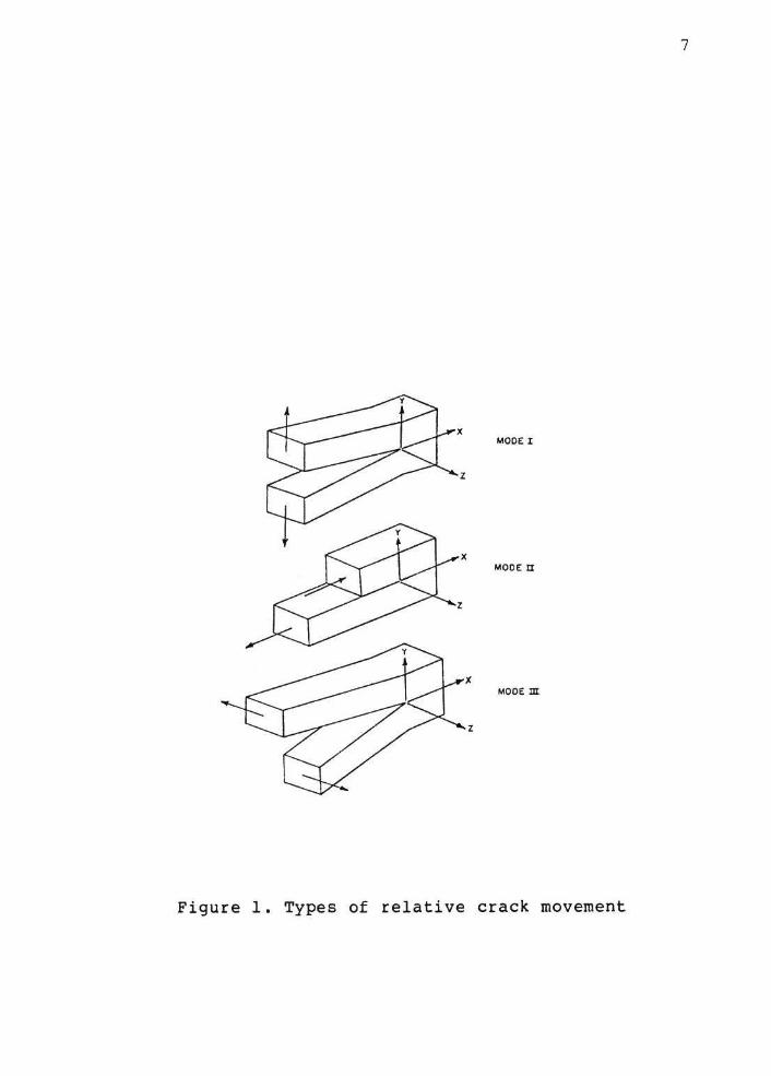
properties . "£61 Three types of relative movement can be
defined to show the movement of two crack surfaces .
This movement is defined as either Mode I , II, or III
3

which correspond to
modes (see Fig. 1).
can be treated as
combination of them.
4
the opening, shear, or tearing
The stress field at a crack tip
either one of these modes or any
The equations for the stress and displacement
fields "show that the distribution of the
elastic-stress fields and of the deformation fields in
the vicinity of the crack tip are invariant in all
components subjected to a given mode of deformation and
that the magnitude of the elastic-stress field can be
described by single-term parameters,Kl, K2, K3, that
correspond to Modes I, II, III, respectively.
Consequently, the applied stress, the crack shape and
size, and the structural configuration associated with
structural components subjected to a given mode of
deformation affect the value of the stress-intensity
factor but do not alter the stress-field
distribution ."£ 61
The magnitude of the stress intensity factor,
K, is directly related to the nominal stress (01 and
the square root of the crack length (a) .
K=<f<g>> <cr> era>
where f(g} is a parameter that depends on the specimen
and crack geometry and has been the subject of

5
extensive investigations and research. Barker has
suggested material testing to determine this .
tasks
A review of the
of this thesis
literature
has been
incorporated a computer assisted
"Engineering Index" [1 and 21
published articles. This review
pertinent to the
done. This survey
of the search
to find
used the
recently
following
combinations of key words in searching abstracts listed
in References 1 and 2 .
1 . Glass Ceramic - fracture mechanics
2. Glass Ceramic - finite element
3. Glass Ceramic - bimaterial interface
The significant articles of this survey are included in
the bibliography .
References 3 and 4 provide very basic and
complete descriptions of brittle fracture of ceramic
materials and References 5 and 6 treat the basics of
linear elastic fracture mechanics . A recent summary of
the state-of- the art in the application of fracture
mechanics to glass ceramics is given in Reference 7 .
Information on fracture mechanics data of glass
ceramics is given in References 8-24 .
The problem of fracture of a bimaterial bond is
covered in general in Reference 25. Of particular
interest is the nature of the oscillatory character of
the stresses in the near crack tip region [261. The
6
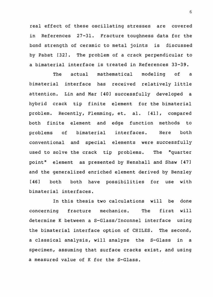
real effect of these oscillating stresses are covered
in References 27-31. Fracture toughness data for the
bond strength of ceramic to metal joints is discussed
by Pabst [32]. The problem of a crack perpendicular to
a bimaterial interface is treated in Refe~ences 33-39.
The actual mathematical modeling of a
bimaterial interface has received relatively little
attention. Lin and Mar [40] successfully developed a
hybrid crack tip finite element for the bimaterial
problem. Recently, Flemming, et. al. [411 , compared
both finite element and edge function methods to
problems of bimaterial interfaces. Here both
conventional and special elements were successfully
used to solve the crack tip ~roblems. The "quarter
point" element as presented by Henshall and Shaw [471
and the generalized enriched element derived by Benzley
[46] both both have possibilities for use with
bimaterial interfaces.
In this thesis two calculations will be done
concerning fracture mechanics. The first will
determine K between a S-Glass/Inconnel interface using
the bimaterial interface option of CHILES. The second,
a classical analysis, will analyze the S-Glass in a
specimen, assuming that surface cracks exist, and using
a measured value of K for the S-Glass.
7
MODE I
MOOE II
MODEm
z
Figure 1. Types of relative crack movement
CHAPTER THREE
CHILES.BYU
Chiles 2 is a FORTRAN finite element computer
program that calculates the intensities of linear
elastic singularities in isotropic and orthotropic
materials. It was authored by Steven E. Benzley and
Zelma E. Beisinger, and prepared by Sandia
Laboratories, Albuquerque, New Mexico and Livermore,
California for the United States Department of Energy.
The abstract for the program reads as follows:
CHILES 2 is a finite element computer program that calculates the strength of singularities in linear elastic bodies. A generalized quadrilateral finite element that includes a singular point at a corner node is incorporated in the code. The displacement formulation is used and interelement compatibility is maintained so that monotone convergence is preserved. Plane stress, plain strain, and axisymmetric conditions are treated. Isotropic and orthotropic crack tip singularity problems are solved by this version of the code but any type of singularity may be properly modeled by modifying selected subroutines in the program. £46]
The above referenced version of CHILES 2 is not
interactive. To run this version the user has to make
a file consisting of a set of problem identification
8

9
lines. The information in the lines has to appear in
certai~ col~mns making the task of creating the file
cumbersome, time consuming, and prone to error. An
interactive version of CHILES 2 named CHILES.BYU was
developed as a part of this thesis. An interactive
program allows a user to be questioned by the computer
program such that the necessary input data may be
generated. The modifications to make CHILES 2
interactive are discussed in what follows .
In modifying CHILES it was essential that the
user of the program be able to easily change data if
erroneous information was input. Therefore, questions
asking if changes need to be made are placed at the end
of sections dealing with common information. For
example, after the questions dealing with the
initialization process are asked, the user is then
asked if any changes are to be made . If no changes are
to be made the program continues on to the next block
of questions to be asked, namely, questions dealing
with the material properties of the specimen. The
program continues through the different blocks of
information until the user is satisfied that all the
information is input correctly .
The program then goes through the solution of
the problem in question . To inform the user that the
program is in the calculation stage, the message

10
"CHILES IS EXECUTING" appears on the terminal. When
calculations cease, the message that two files,
CHILES.LIS and CHILES.MOV, have been made appears.
CHILES.LIS is a file listing information such as
stresses, strains, connectivity, and node point
coordinates of a problem. CHILES.MOV is a file
containing plotting information that is to be used in
conjunction with a graphics program in displaying
computed data. The program then tells the user that
calculations are complete and signs off. The
limitations and capabilities of CHILES.BYU are
explained in Appendix A.

CHAPTER FOUR
Actuator Specimen Design Analysis
I. DESCRIPTION OF TEST SPECIMENS
As a part of this thesis the modeling of
fracture of glass ceramics and glass ceramic/metal
interfaces will be demonstrated using CHILES.BYU.
Three test specimens will be designed . The
specimens will be composed of three materials . The
properties of these materials are given as follows:
Inconnel 718 Modulus of Elasticity: 29 . 0 E6 psi Poisson's Ratio: 0 . 294 Yield Stress: 13.0 E4 psi Expansion: 0 . 00975
S-Glass Modulus of Elasticity: 13 . 0 E6 psi Poisson's Ratio: 0.200 Yield Stress: None Expansion : 0 . 00882
Hastalloy Modulus of Elasticity: 29.8 E6 psi C-276 Poisson's Ratio: 0 . 300
Yield Stress: 57.8 E3 psi Expansion: 0.00930
11

12
The three specimens are all variations of the
same basic shape with different dimensions to produce
failures at different locations in the specimen. The
goal is to have three different designs that will
produce failures at:
a) the S-Glass/Inconnel interface
b) the S-Glass alone
c) the S-Glass/Hastalloy interface
The basic test specimen from which the others were
modeled is shown i n Fig. 2.
The S-Glass/Inconnell interface specimen is
designed to produce a critical stress area between the
Inconnel and S-Glass. The S-Glass specimen is designed
to produce failure on the S-Glass su£faces.
done by maximizing the bending that will occur
S-Glass and minimizing the effect
S-Glass/Inconnel interface. The S-Glass/Pin
This is
in the
of the
failure
specimen is designed to produce a critical stress area
between the S-Glass and Hastalloy. This occurs at the
point of maximum bending at the bottom of the specimen
between the S-Glass/Hastalloy interface.
Since the specimens are symmetrical about their
central axis only half of each specimen is modeled.
The finite element meshes were created by keeping each
element as square as possible though a length to width
ratio of 2:1 was allowed . Critical areas were defined

13
more completely by a finer mesh while areas of lesser
interest and importance were modeled more coarsely .
Three colors were assigned to the three different
materials that make up the specimens. Hastalloy is
gold, S-Glass is red, and Inconnel is turquoise.
Pictures of the specimen designs, with the finite
element grid overlaying each specimen, are shown in
Figs. 3 thru 5.

.Ollt\
.,oo
.SH"
-~•Z. 4f0
,l.fQ
·2.'1$"
I '\....o,oRI
J II * ~ . 100
Figure 2. Basic Test Specimen
1
Figure 3. F.E. grid over color parts S-Glass/Inconnel
14

Figure 4. F . E. grid over color parts S- Glass
Figure 5 . F. E. grid over color parts S- Glass/Pin
15

1 6
II. RESULTS OF TEST SPECIMENS ANALYSES
Boundary conditions are applied to the finite
element models to allow them to behave in a manner
which simulates their real behavior. A pressure of
50,000 psi is applied to the inner surface of the
specimens. The models are constrained, and the
pressure is applied, according to the basic test
specimen shown in Fig. 6.
The deformed geometries of the models must be
magnified many times to allow the viewing of the
deformed shape. The deformation of each model,
produced by the 50,000 psi load, is shown in Figs. 7
thru 9.
The stresses developed in the specimens can be
thought of as being distributed in the model according
to contours or fringes. The fringes will be modeled in
five colors with blue being the lowest stress and red
being the highest stress. The Von Mises color stress
fringes in the S-Glass of each model are shown in Figs.
10 thru 12.
The radial color stress fringes in the S-Glass
of each model are likewise important. These stresses
are shown in Figs. 13 thru 15.
17
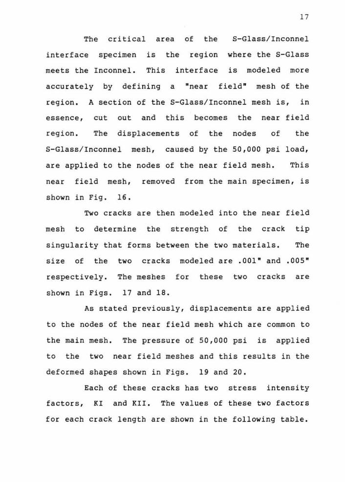
The critical area of the
interface specimen
meets the Inconnel .
is the region
S- Glass/Inconnel
where the S-Glass
This
accu r ately by defining a
interface is
"near fie l d "
modeled more
mesh of the
region . A section of the S-Glass/Inconnel mesh is , in
essence, cut out and this becomes the near field
region . The displacements of the nodes of the
S-Glass/Inconnel mesh , caused by the 50 , 000 psi load ,
are applied to the nodes of the near field mesh . This
near field mesh , removed from the main specimen, is
shown in Fig . 16 .
Two cracks are then modeled into the near field
mesh to determine the strength of the crack tip
singular ity that fo r ms between the two materials. The
size of the two cracks modeled are .001" and . 005"
respectively. The meshes for these two cracks are
shown in Figs. 17 and 18.
As stated previously, displacements are applied
to the nodes of the near field mesh which are common to
the main mesh . The pressure of 50,000 psi is applied
to the two near field meshes and this results in the
deformed shapes shown in Figs. 19 and 20.
Each of these cracks has two stress intensity
factors, KI and KII . The values of these two factors
for each crack length are shown in the following table .

Crack Size
.001"
.005"
KI
11 , 720 13 , 881
18
KII
-13,473 -20,907
A classical analysis of a surface crack on the
S-Glass will now be described . Data supplied [50]
indicates that machining flaws on the surface of the
S- Glass could range from 50-100 microns deep and be
100-200 microns long . Such flaws could be assumed to
be semi-circular . For such a flaw, the stress
intensity factor, KI, can be determined from the
following analysis [51 .
For a semi- circular flaw
1/2 1/2 KI=l.l (<T') (<T') (a/Q)
where KI=Stress Intensity Factor <T'=Applied Stress a=Crack depth Q=Flaw Shape parameter (apprx . =2 . 4)
1/2 Thus KI=l.259(~) (a)
Using the measured value of K 1620 psi; we obtain
1/2 1287/<J=(a)
for S-Glass [50] of
Applying this equation the graph in Figure 21
can be drawn. This figure can be used to determine the
critical flaw depth for a semi-circular crack along the
surface of the S-Glass. Note that the expected flaw

19
size of 100 microns (i.e. .003937") corresponds to a
stress level of approximately 20,000 psi stress.
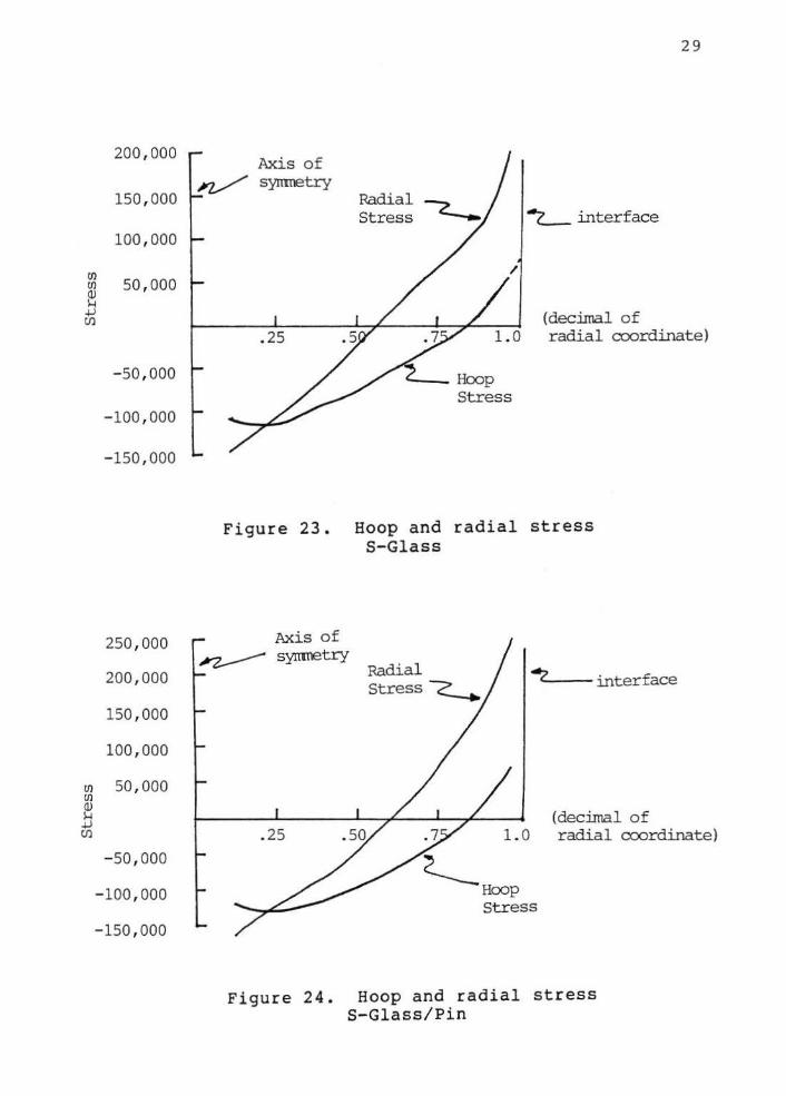
Plots of hoop and radial stresses along the
surface of the S-Glass for the three specimens are
shown in Figures 22 thru 24. The value of tensile
stress in the hoop direction (i.e. circumferential),
for all three specimens, is significantly lower than
the tensile stress in the radial direction, thus
failures originating from surface flaws on the S-Glass
are most likely to occur from radial stresses. Figures
22 thru 24 show that the highest values of tensile
stress and the greatest
20,000 psi tension occur
S-Glass
in the
surface area above
S-Glass specimen.
Consequently this specimen
failures along the S-Glass
S-Glass/Inconnel interface.
is most likely to produce
surface away from the

Unifonn Pressure
50 , 000 psi -+
Symretry -z....... line
20
Figure 6. Boundary conditions on basic test specimen
Figure 7 . Deformed geometry (S- Glass/ Inconnel)

21
Figure 8 . Defor med geometry (S-Glass )
Figure 9 . Defor med geometry (S-Glass/ Pin )

22
Figure 10. Von Mises Stress Fringes (S-G1ass/Inconne1) Range: 2,755 psi - 77,000 psi
Figure 11. Von Mises Stress Fringes CS-G1ass) Range: 5,506 psi - 170,000 psi

Figure 12 . Von Mises Stress Fringes (S-Glass/Pin) Range: 13 , 800 psi - 319,000 psi
Figure 13. Radial Stress Fringes (S-Glass/Inconnel) Range: -400 psi - 23,750 psi
23

Figu r e 14 . Radi a l Stress Fringes (S- Glass ) Range: - 171,430 psi - 100 , 000 psi
Figure 15 . Radial Stress Fringes (S-Glass/ Pin ) Range: -189 , 000 psi - 309 , 000 psi
2 4

25
~ .... ~ ~ ~ ~ ~ ~ ~ ~ .... """ ~
""" ~ ~ ....
""' ~ ""' ~
.... ~ ~ .... ~ ~
""" ~ looo,
""' ~ looo, -...
~ ""' ... "" ~ ... ~ ... ~ ... ...
""' .... """'
... ~"" ... ... ""' ~ ... ...... ... ~
.... ~ ... ~ .... .... ~ .... ~
.... ... """ ~ .... ...
"" """ ~
""" ...
""" ~"""
""" """ ...
"""
....... .... .... "'"'"" - ---------~ ~~ .... "'"~ ... .....
~ ~...,
1 r "'" - r -T I
.......::::;...; 1 r
~ ...
~ ...
~~ ; ~ ~~ ~ ::: ~-~:.... -J....
I I 1 I 1 1 I
j 1 I I I I I
j II I J
Figure 16. Near field mesh removed from main specimen

26
Figure 17. Near field mesh- .001" crack
Figure 18. Near field mesh - . 005" crack

27
Figure 19. Deformed shape - .001 " crack
Figure 20. Deformed shape - . 005" crack

100,000
(j)
~ 50,000 14 +l U)
(20,000)
60 , 000
40,000
(j)
20,000 (j) Q) 14 +l (i)
-20,000
.001 .002 . 003
Critical crack length, a cr
.004
Figure 21. Stress vs. crack size
I Radial I Stress I <-..,t
"t.__ interface
I /
(decimal of
28
.25 1.0 radial coordinate)
Hoop Stress
Figure 22. Hoop and radial stress S-Glass/Inconnel
200, 000
150, 000
100 , 000
en 50, 000 en
~ +' (/)
- 50 ,000
- 100, 000
-150,000
250 , 000
200 , 000
150 , 000
100 , 000
en en
50 , 000 Q) H +' (/)
- 50 , 000
- 100 , 000
- 150, 000
29
Axis of syrrrretry
Radial Stress ""'(__interface
(decimal of radi al coordinate)
Figure 23. Hoop and radial stress S-Glass
Radial Stress -c__.
<-___
4z.__ __ interface
(decimal of 1.0 radial coordinate)
Hoop Stress
Figure 24. Hoop and radial stress S-Glass/Pin

30
III . EVALUATION OF RESULTS
basic
The specimen designs were all derived from a
specimen and modeled to produce different
critical areas. The results obtained from. the analysis
of the three test specimens indicate that each specimen
will fail at a different location.
The S-Glass/Inconnel interface failure specimen
was designed to produce a critical region at the
S-Glass and Inconnel interface. To further analyze
this region a near field mesh was defined and two
different size cracks were introduced between the two
materials. A fracture mechanics analysis using the
near field meshes shows that as the size of the crack
increases, the value of KI increases. Material testing
as suggested by Barker is required at this point to
determine a value of toughness for such a bimaterial
interface.
The S-Glass failure specimen was modeled with a
geometric discontinuity along the lower surface. An
area of high stress should be produced at this
discontinuity.
CHILES.BYU shows
Analysis of this
that high stresses
problem using
exist at the
discontinuity but also that significant bending is
caused by the discontinuity. These bending regions
produce high tensile stresses at the top and bottom of
the S-Glass on opposite ends of each other. Therefore,
31
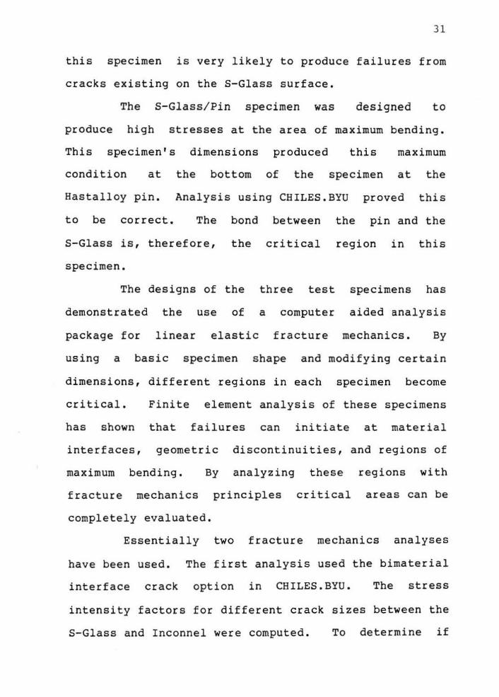
this specimen is very likely to produce failures from
cracks existing on the S-Glass surface.
The S-Glass/ Pin specimen was designed to
produce high stresses at the area of maximum bending.
This specimen's dimensions produced this maximum
condition at the bottom of the specimen at the
Hastalloy pin. Analysis using CHILES.BYU proved this
to be correct. The bond between the pin and the
S-Glass is, therefore, the critical region in this
specimen.
The designs of the three test specimens has
demonstrated the use of a computer aided analysis
package for linear elastic fracture mechanics. By
using a basic specimen shape and modifying certain
dimensions, different regions in each specimen become
critical. Finite element analysis of these specimens
has shown that failures can initiate at material
interfaces, geometric
maximum bending. By
discontinuities, and regions of
analyzing these regions with
fracture mechanics principles critical areas can be
completely evaluated.
Essentially two fracture mechanics analyses
have been used. The first analysis used the bimaterial
interface crack option in CHILES.BYU. The stress
intensity factors for different crack sizes between the
S-Glass and Inconnel were computed. To determine if

32
these interface cracks are critical, the computed
stress intensity factor must be compared to laboratory
measured values of fracture toughness of
S-Glass/Inconnel bonds. By comparing the computed
values and measured values critical crack size can be
computed.
The second analysis assumed machining flaws
would produce surface cracks from 50-100 microns deep
and 100-200 microns long. Assuming the flaws to be
semi-circular a stress intensity value KI can be
determined to be KI=l.259(~) (~). Using a value of
KI=l620 psi a graph of stress vs. critical length can
be drawn. By plotting the hoop and radial stresses
along the surface of the S-Glass the area where stress
corresponds to critical crack size can be found.

CHAPTER FIVE
Conclusions and Recommendations
The principal contribution of this thesis was
the development of an interactive version of the CHILES
Fracture Mechanics program. With this program an
engineer can easily modify the size and location of
cracks. A structure ' s shape can also easily be changed
to analyze different situations. Fracture mechanics
analyses can then be performed on these situations .
Two methods have been used to perform fracture
mechanics analyses . The single or bimaterial interface
option in CHILES.BYU can be used to calculate the
stress intensity factors of a crack . A classical
surface flaw analysis can also be performed by assuming
a crack size and shape and using a computed stress
field. Critical stresses for specific crack sizes and
shapes can then be calculated.
The package of QMESH . BYU CHILES . BYU
MOVIE.BYU allows an engineer to rapidly investigate
different crack configurations and display the results
using color graphics. This visual aid allows the
33
3 4
engineer to analyze and investigate the results of
critical areas .
Although CHILES . BYU is interactive and
"user-friendly" the following modifications could be
incorporated into the software. 1- Error checks could
be used such that if a number is input that does not
follow the prescribed format, the program would not
terminate. 2- More selective editing could be used
than is available. Instead of having to modify a whole
block of entries it would be useful to edit just one
individual entry at a time and not be required to input
all entries to correct a single error. 3- An echo of
data input should be pr ovided to allow the user to see
all the input data . These above improvements would all
be very useful to improve the "user-friendliness" of
CHILES.BYU.

BIBLIOGRAPHY

BIBLIOGRAPHY
[1] Compendex, (Copr. Engineering Index Inc. )
[2] ISMEC: Mechanical Engineering, {Copr. Cambridge Sci. Abs)
[3] Liebowitz H., Fracture, An Advanced Treatise, VII, 1972, Academic Press , New York .
[4] Jayatilaka, Ayal des., Fracture of Engineering Brittle Materials. 1979, Applied Science Publishers, T.td . , London .
(5] &roek, D., Elementary Engineering Fractur e Mechanics, 1974 , Noordhoff, Leyden.
[6] Rolfe, S . T. , and J , M. Barson , Fracture and Fatigue Control in Structures, 1977, Prentice Hall, Englewood Cliffs, New Jersey.
[7] Mecholsky, J.J., "Fracture Mechanics Analysis of Glass Ceramics, .. Special Pub., Advances in Ceramics, American Ceramic Society, 1982.
(8] Szendi- Horvath, G., "Fracture Toughness Determination of Brittle Materials Using Small to Extremely Small Specimens," Eng. Fract. Mech., vl3 , no . 4, 1980.
[9) Hofmann , V. , 0. Henkel, and D. Schulze, Mechanical Behavior of Solids in Dependence on Their Structure - Glass , Ceramics , Polymers, 1976," Arag-Verlag, Berlin, 1976.
[ 10] Marion. R.H., "Use of Indentation Fracture to Determine Fracture Toughness," ASTM STP 678, 1979.
[11) Ritter, J.E., "Engineering Design and Fatigue Failure of Brittle Materials," Fract Mec. of Ceram, v.4, Symp on Fract Mech of Ceram, Proc, Pa. State Univ., University Park, 1977.
(12] Ritter, J . E. , "Strength and Failure Predictions for Glass and Ceramics," J , Am. Ceram. Soc., v.S9, no . 11, 1976.
[13] Wiederhorn, S. M., E.R. Fuller, J , Mandel, and A.G. Evans , "Error Analysis of Failure Prediction Techniques Derived from Fracture Hechanics," J. Am. Ceram. Soc. , v . 59, no . 9-10, 1976, p. 403-411.
[14] Pisarenkg , G.S., Y.I. Kozub, U.G. Soluganou, and A.P. Poleshko, "Evaluation of the Strength of Brittle Materials by Studying the Fracture Surface," Acad. of Sci., Kiev, UKr SSR.
[15) Hecholsky, J . J., and s.w . Freiman , "Fracture Surface Analysis of Glass Ceramics," Eleventh International Glass Congress, Prague, Czechosolvakia, 1977.
(16] Mecholsky , J . J . , s . w. Freiman , and l:LW. Rice , "Fracture Surface Analysis of Ceramics," J, Mat. Sci. ..!:..!..• 1310-19, 1976.
36

37
[17] Bansal, G.K., w. Duckworth, and D.E. Niesz , Bull. Am. Ceram. Soc. 55. (3), 298-92, 1976.
(18] Lewis III, D.L., "Fracture Strength and Mirror Size in A Commercial Glass-Ceramic," J, Am. Ceram. Soc. 64, (2) 82-86, 1981.
(19] Mecholsky, J.J., C.T. Moynihan, P.B. Macedo , and G. R. Srinivasn, "Microstructure and Properties of an Infrared Transmitting Chalcogenide Glass Ceramic , " J. Mat . Sci. .!.!:.• 1952- 60, 1976.
(20] Govila, R.K., K.R. Kinsman, and P. Beardmore . "Fracture Phenomenology of a. Lithium-Aluminum-Silicate Glass Ceramic," J, Mat. Sci • .!2• 2081-91, 1978 .
[21] Swearengen, J.C. , E.K. Beauchamp, and R.J . Eagan, "Fracture Toughness of Reinforced Glasses," Fracture Mechanics of Ceramics op.cit., v. 4 , 973-987, 1978.
[22] Evans, A.G., A.H. Rever, D.L. Porter , "The Fracture Toughness of Ceramics," Fracture 1977, v. 1, ICF4 , Waterloo, June 1977.
{23] Henshall, J.L., D.J. Roucliffe, and J . W. Edington, '"The Measurement of K and Subcritical Crack Propagation Rates in Hot Pressed Sic and Si N ... Fracture 1977, v. 3, ICF4, Waterloo, June 1977 .
[24] Abdel-Latif, A I.A., R.E. Tressler, and R.C., Bradt., "Fracture Mirror Formation in Single Crystal Alumina," Fracture 1977, v. 3, ICF4, lolaterloo, June 1977.
(25] Anderson, G.P., S.J. Bennett, and K.L. DeVries, Analysis and Testing of Adhesive Bonds, Academic Press, New York, 1977 .
[26] W:l.lliams, M.L., "The Stresses Around a Fault or Crack in Dissimilar Media," Bull. Seis. Soc. Am., V. 49, 1959, pp 199-204.
[27] Rice, J.R., G.G. Sih, "Plane Problems of Cracks in Dissimilar Media," J. of App. Mech., ASME, V. 32, 1965, pp. 418-423.
[28] Erdogan, F., "Stress Disbribution in Bonded Dissimilar Materials with Cracks," J, of App. Mech., ASME, V. 32, 1965, pp . 403-410.
[29] England, "A Crack Between Dissimilar Media," J, of App. Mech., ASME, v. 32, 1965, pp. 400-402.
[30] Mak, A.F., and L.M. Keer, "No-Slip Edge Crack on a Bimaterial Interface, " J. of App. Mech., ASME, v. 47, 1980, pp 816-820.
[31] Theocaris, P.S., and E.E. Gdoutas, "Stress Singularities in Cracked Composite Full-Planes," Int, J, Fracture, v. 13, n. 6, 1977, pp 763-773.
[32] Pabst, R., and G. Elssner, "Bond Fracture Strength in Ceramic-to-Metal Joints," Fracture 1977, ICF4, v. 3, pp 1025-1029 .

38
[33] Tracey, D.M., and T.S. Cook, "STRESS Distribution in a Cracked Bimaterial Plate," Irac_t~re 1977, !CF4, v. 3, 1977, pp 1055-1058.
[34] Theocaris, P.S., J , Milios, "Crack-Arrest at a Bimaterial Interface," Int J. Solids Struct., v. 17, n. 2, 1981, pp 217-230
[35] Ioakimidia, N.I., P.S. Theocaris, "Practical Evaluation of STRESS Intensity Factors at Semi-Infinite Crack Tips," Eng . Fract. Mechj., v. 13, n. 1, 1980 , pp 31-42.
[36] Theocaris, P.s., and E.E. ,Composite Full-Planes," Int. 763-773.
Gdoutos, "STRESS Singularities in Cracked J. Fracture, v. 13, N. 6, Dec 1977, pp
[37] Erodogan, F., "Fracture of Composite Materials," Prospects of Fract. Mech. Int. Conf., Proc . Delft, Neth . June 1974, pp 477-492.
[38] Ashbaugh, N., "STRESS Solution for a Crack at an Arbitrary Angle to an Interface," Int. J. Fract., v . 11, n. 2, April 1975, pp 205-219.
[39] Ashbaugh, N., "On the Opening of a Finite Crack Normal to an Interface," J . All. Mech . , ASME, v . 40, n . 2, June 1973, pp 626- 628 .
[40] Lin . K.Y., and J.W. Mar, "Finite Element ANalysis of Stress Intnesity Factors for Cracks at a BiMaterials Interface," Int. J. Fract., V. 12 , n .4, Aug 1976.
[41] Flemming, J.F., J . R. Guydisk , J.R . 1enta, C.E. Ronnion, "The Finite Element Method vs the Edge Function Method for Linear Fracture Analysis," Eng. Fract . Mech., v. 13, pp 42-55, 1980.
[42] Randall, P.N., Plain Strain Crack Toughness Testing of High Strength ~etal1ic Materials, ASTM 410, ed. W.F. Brown, Jr., and J.E. Srawley , 88-126' 1966.
[43] Benchmark Editorial Committ ee of the SESA Fracture Committee, "A Critical Evaluation of Nume r ical Solutions to the 'Benchmark' Surface Flaw Problem," Experimental Mechanics, 253-64, Aug 1980.
[44] Tada , H., P. Paris, and G. Irwin, "The Stress Analysis of Cracks Handbook, " Del Research Corporation, Hellectown, Pa., 1973.
[45] Parmerter, R. Reid, "Stress Intensity Factor for Three-Dimensional Problems," AFRPL-TR-76-30, Air For ce Rocket Propulsion Laboratory, Edwards AFB, California , 1976.
[46] Benzley , S.E., and Z. E. Beisinger, "CHILES---A Finite Element Computer Program That Calculates the Intensities of Linear Elastic Singularities", Sandia Lab., Rep. No . SLA-73- 0894, Albuquerque , New Mexico (September 1973).
[47 ] Henshall. R.D., and K.G. Shaw, "Crack Tip Finite Elements are Unnecessary", IJNME, Vol. 9, No. 3, 1975, pp. 495-507.

39
[48] Grandt, A.F., "Two Dimensional Stress Intensity Factor Solutions for Radially Cracked Rings," Technical Report, AFML-TR-75- 121, WrightPatterson AFB, Ohio, 1975.
[49] Warkington, W.E . , "Development of a Computer Aided Analysis Package for Linear Elastic Fracture Mechanics," Masters Thesis, Brigham Young University Provo, Utah, 1983.
[SO] Private Communication with J . J. Mecholsky.
[51] Parks, V.J., Sanford, R.J. "Photoelastic Stress and Fracture Analysis of Two Neutron Tube Designs," preliminary report to SLA.

APPENDIX A
CHILES.BYU USER'S GUIDE

41
C H I L E S . B Y U
(CHILES • BRIGHAM YOUNG UNIVERSITY)
AN INTERACTIVE FINITE ELEMENT COMPUTER PROGRAM THAT
CALCULATES THE INTENSITIES OF LINEAR ELASTIC SINGULARITIES
IN ISOTROPIC OR ORTHOTROPIC MATERIALS AND ALONG
BIMATERIAL INTERFACES
AUGUST 1982 EDITION
The computer program described in this document is available from Brigham Young University. Neither Brigham Young University nor their employees makes any warranty, expressed or i mplied, or assumes any legal responsibility for the accuracy, completeness or usefulness of this program and document.
42
ABSTRACT
CHILES.BYU is a finite element computer program
that calculates the strength of singularities in linear
elastic bodies. A generalized quadrilateral finite
element that includes a singular point at a corner node
is incorporated in the code. The displacement
formulation is used and interelement compatibility is
maintained so that monotone convergence is preserved.
Plane stress, plane strain and axisymmetric conditions
are treated. Isotropic and orthotropic crack tip
singularity problems are solved by this version of the
code but any type of singularity may be properly
modeled by modifying selected subroutines in the
program. This program also
intensity factor of crack
bimaterial crack option.
calculates the stress
tip problems using a

43
PROGRAM CAPABILITIES AND LIMITATIONS
1. CHILES performs a linear elastic stress analyses of any two-dimensional body in a plane stress, plane strain or axisymmetric state. Singular points are treated with enriched finite elements.
2. Up to three singular nodes may be defined in the body.
3. 1000 nodal points may be used.
4. 1000 elements may be used.
s . Bandwidth is limited to 54 (i.e . , difference between node numbers in any one element must be < 27) •
6. Mechanical and thermal loads are accepted.
7. A pre-created mesh and boundary condition scheme must be read from a file.
8 . Displacements, stresses, and strains are output on the file CHILES.MOV for plotting.
9. CHILES.BYU automatically surrounds a singularity with type A and type B elements.
10. Small strains are assumed, a condition that is violated at the crack.
11. Up to 10 different materials can be defined.
12. Special elements are compatible with conventional elements.
13 . Users may replace subroutines (CALQ and CALQI) to model singularities other than crack tips.

44
INTRODUCTION
This user's guide describes how to use the program CHILES.BYU. Each block of required input data is described in detail in the order requested by CHILES . BYU. In this way, the user can follow the guide in the same order that the data is requested . This guide is not intended to describe the theory of finite element analysis and the specific fracture mechanics elements in the program but is a step-by- step guide to allow someone inexperienced with CHILES . BYU to be able to use the program with ease. For a more thorough description of CHILES.BYU and its development the user should refer to CHILES 2 by Benzley and Beisinger; available through Sandia Labs . After each block of information is input a question asks if any changes are to be made . If changes are to be made input "yes" and re-input that block of information. If no changes are to be made input "no" and the program will continue on to the next block of information .
I. PROBLEM IDENTIFICATION INFORMATION
The first block that is required in the program is the initial problem identification data. This data identifies the scope of the problem to be analyzed. The specific input prompt is given followed by an explanation of the data requested by the prompt. All numerical values of this block must be entered in integer format Ci.e. no decimal).
<ENTER TITLE OF PROBLEM>
This request requires a statement of identification for the problem. A maximum of 80 characters is allowed .
<ENTER NUMBER OF SINGULAR POINTS (3 MAX . )>
A value of zero to three is to be entered for this question . CHILES can handle up to three singular points.
<ENTER 1,2 , OR 3 FOR AXISYMMETRIC, PLANE STRESS, OR PLANE STRAIN GEOMETRY>

The geometry selector question asks for either 1 to be entered for axisymmetric geometry, 2 to be entered for plane stress geometry, or 3 to be entered for plane strain geometry.
<ENTER NUMBER OF MATERIALS (10 MAX.)>
This asks for the number of materials which make up the problem being analyzed. Enter any number from one thru ten with ten being the maximum number of materials the program can handle.
<ENTER 0 FOR REDUCED OUTPUT OR 1 FOR EXTENDED OUTPUT>
This deals with the amount of information contained in the CBILES.LIS file. Reduced output contains stresses, strains, and displacements. Extended output contains loading information, connectivity, stresses, strains, and displacements.
<ENTER 0 FOR NO BOUNDARY CONDITIONS ON INTENSITIES OR 1 TO ALLOW INTENSITY BOUNDARY CONDITION TO BE READ>
This gives the user the option of putting boundary conditions on intensities. Zero for none or one to allow.
<ENTER 0 TO READ QMESB FILE OR 1 TO INPUT GEOMETRY POINT BY POINT>
If a finite element mesh file has already been created input zero; otherwise input one and the geometry of the problem will input point by point.
<ENTER NUMBER OF BOUNDARY FLAGS AS SET IN QMESB >
This asks for the number of boundary flags which will be applied to the problem. Input the actual number that will be used.
<ENTER 0 FOR ISOTROPIC MATERIAL OR 1 FOR ORTBOTROPIC MATERIAL>
Isotropic material properties will be specified if 0 is input; orthotropic properties if 1.
45

4 6
II. MATERIAL PROPERTY INFORMATION (ISOTROPIC)
If there were no changes to be made for the first block of information the program continues to the material properties section of the program. For isotropic materials the program will ask three questions for each material . It asks these questions for one material then continues on to the next material in chronological order until all material properties are defined . All numerical values of this block must be entered in real format (i.e . a number including a decimal) .
<ENTER YOUNGS MODULUS FOR MATERIAL (n)>
This entry s pecifies Yo~ng's modulus for the material number defined by the (n ) .
<ENTER POISSONS RATIO FOR MATERIAL (n )>
This entry specifies Poisson's ratio for the material number defined by the (n) .
<ENTER COEF. OF THER . EXPANSION FOR MATERIAL (n) >
This entry specifies the coefficient of thermal expansion for the material number defined by the (n) •
II . MATERIAL PROPERTY INFORMATION (ORTHOTROPOIC )
If orthotropic materials are used this block of materi a l property questions will be asked . For each material seven entries will be required .
<ENTER Ell FOR MATERIAL (n )>
This entry specifies Young ' s modulus in the first principle direction of material orthotropy .
<ENTER Vl2 FOR MATERIAL (n) >
This entry specifies Poisson's ratio in the 1-2 plane.

<ENTER E22 FOR MATERIAL (n)>
This entry specifies Young's modulus in the second principle direction of material orthotropy.
<ENTER E33 FOR MATERIAL (n)>
This entry specifies Young's modulus normal to the plane of analysis.
<ENTER V31 FOR MATERIAL (n)>
This entry specifies Poisson's ratio in the 1-3 plane.
<ENTER V32 FOR MATERIAL (n)>
This entry specifies Poisson's ratio in the 2-3 plane.
<ENTER SHEAR MODULUS FOR MATERIAL (n)>
This entry specifies the shear modulus for the material in question.
<ENTER ANGLE FOR PRINCIPAL AXES>
This entry specifies the angle the principal axes of orthotropy make with respect to r-z coordinates.
III. FINITE ELEMENT MESH FILE INFORMATION
47
This block deals with the finite element mesh file that will be read by CHILES.BYU. Currently this is the data file written by the QMESH.BYU mesh generator. Any file name can be used • It is important to insure that the difference between node numbers in any one element be less than 27 for bandwidth considerations.
<SPECIFY QMESH FILE>
This asks to input the name of the finite element mesh file.

48
IV. BOUNDARY CONDITION INFORMATION
This block of information defines the different boundary conditions (i.e. displacements, forces, shear tractions, and normal tractions) that can be placed on sides or nodes of a mesh. The boundary flags that specify the location of the intended condition are defined in the QMESH file. A table describing the various codes is given below. All numerical values except the boundary flag number must be entered in real format .
CODE Radial ( r) Axial (z) ---------- ---------
0 . 0 Force Force 1 . 0 Displ Force 2.0 Force Displ 3 . 0 Displ Displ
<ENTER BOUNDARY FLAG NUMBER AS SET IN QMESH >
This entry defines the boundary flag number that has been defined in the QMESH file .
<ENTER BOUNDARY CODE>
This entry specifies the boundary code that will be applied to all nodes with a boundary flag as defined above . If the boundary code is greater than or equal to zero the boundary codes are defined in the table above and the next two entries are nodal forces or displacements . If the boundary code is less than zero the next two entries are the normal and shear tractions on an element face.
<ENTER XR OR PN VALUE OF DISPLACEMENT, FORCE OR NORMAL TRACTION>
Enter the proper value according to the boundary code used.
<ENTER XZ OR SH VALUE OF DISPLACEMENT, FORCE OR SHEAR TRACTION>
Enter the proper value according to the boundary code used .

49
V. DEFINITION OF A SINGULAR .POINT
This block of information defines the singular points . Fracture mechanics analyses of single material interfaces and bimaterial interfaces use this option of CHILES . BYU. A maximum of three singular points can be defined . All numerical values except the angle phi must be ente r ed in integer format . Phi must be entered as a real number.
DO YOU WISH TO DEFINE A SINGULAR POINT?
This asks if a singular point is to be defined. If not , input no .
<ENTER SINGULAR REGION>
Input the number which corresponds t o the specific singular point, ( i . e. 1 ,2, or 3) .
<ENTER NODE NUMBER OF CRACK TIP>
The node number of the crack tip is entered here. This can be determined from a listing of the finite element mesh or displaying the mesh using a graphics program to determine what node number corresponds to the crack tip .
<ENTER ANGLE PHI OF CRACK>
Enter angle , in degrees, that the crack makes with the r - axis .
<ENTER REFERENCE MATERIAL FOR SINGULAR REGION>
Enter the number of the material that surrounds the singular region defined above.
<ENTER ADJACENT MATERIAL FOR SINGULAR REGION>
If a single material crack interface is being defined this entry is the same material number as the reference material entered above . If a bimaterial crack interface is being defined, this entry is the material on the opposite side of the interface from the reference material entered above . The stress intensity factors are normalized with respect to the reference material .

50
VI. DEFINITION OF BOUNDARY CODE FOR A NODE
This block of information allows the definition of a boundary code for a node . This option is useful if a boundary condition is needed to be specified for a node that does not have an associated boundary flag . Instead of using a boundary flag number as a reference the node number is used. All numerical values except the node number must be entered as a real number .
DO YOU WISH TO DEFINE A BOUNDARY CODE FOR A NODE?
If this is not needed input no.
<ENTER NODE NUMBER>
Enter the specific node number to be constrained. This number can be obtained from either a listing of the finite element mesh or from a graphics display .
<ENTER BOUNDARY CODE>
Enter this according to the chart in section IV .
<ENTER XR VALUE>
Enter this as described in section IV .
<ENTER XZ VALUE>
Enter this as described in section IV.

APPENDIX B
CHILES . BYU PROGRAM LISTING

c c c c c c c c c c c c c c c c c c c c c c c c c c c c c c c c c c c c c c c c c
PROGRAM CHILES2V OPEN (UNIT~6, TYPE= ' NEW' ,ACCESS='SEQUENTIAL ' ,NAME~ ' CHILES . LIS 1 ) OPEN (UNIT=10,TYPE= 1 NEW' ,ACCESS='SEQUENTIAL',NAME='CHILES . MOV 1
,
1 FORM•'UNFORMATTED') OPEN CUNIT=1' TYPE a I SCRATCH I 'ACCESS= '.SEQUENTIAL I '
1 FORH• ' UNFORHATTED 1)
OPEN (UNIT•2, TYPE='SCRATCH',ACCESS='SEQUENTIAL', 1 FORM•'UNFORHATTED ' )
OPEN (UNIT=.,TYPE='SCRATCH 1 ,ACCESS•'SEQUENTIAL') OPEN (UNIT=12,TYPE= ' SCRATCH 1
1 ACCESS•'SEQUENTIAL', 1 FORM•'UNFORHATTED 1
)
CALL CHILES2 CLOSE CUNIT=l) CLOSE CUNIT:.2) CLOSE (UNIT=4) CLOSE CUNIT•6) CLOSE (UNIT=9) CLOSE <UNIT:.10) CLOSE (UNIT=12) CLOSE (UNIT•13)
END SUBROUTINE CHILES2
CHILES 2V
S. E. BENZLEY W. E. WARKENTIN
CIVIL ENGINEERING DEPARTMENT BRIGHAM YOUNG UNIVERSITY, PROVO, UTAH, 84602
CHILES RELEASED SEPTEMBER 1973 CHILES2 RELEASED AUGUST 1977
CHILES 2V RELEASED AUGUST 1982 CHILES IS A. FINITE ELEMENT COMPUTER PROGRAM THAT CALCULATES THE STRENGTH OF SINGULARITIES IN LINEAR ELASTIC BODIES. A GENERALIZED QUADRILATERAL FINITE ELEMENT THAT INCLUDES A SINGULAR POINT AT A CORNER NODE IS INCORPORATED IN THE CODE. THE DISPLACEMENT FORMULATION IS USED AND INTERELEMENT COMPATIBILITY IS MAINTAINED SO THAT MONOTONE CONVERGENCE IS PRESERVED. PLANE STRESS, PLANE STRAIN AND AXISYMMETRIC CONDITIONS ARE TREATED. ISOTROPIC AND ORTHOTROPIC CRACK TIP SINGULARITY PROBLEMS ARE SOLVED BY THIS VERSION OF THE CODE AS WELL AS A SPECIAL APPROXIMATE TREATMENT OF A BIMATERIAL INTERFACE CRACK. ANY TYPE OF SINGULARITY HAY BE PROPERLY MODELED BY MODIFYING SELECTED SUBROUTINES IN THE PROGRAM.
52
* * * * * * * * * * * * * * * * * * * * * * * * * * * * * * * * * * * CHILES WAS ISSUED BY SANDIA LABORATORIES, * * A PRIME CONTRACTOR TO THE * * UNITED STATES ATOMIC ENERGY COMMISSION * * * * * * * * * * * * * * NOTICE * * * * * * * * * * * * * * * * THIS REPORT WAS PREPARED AS AN ACCOUNT OF WORK SPONSORED BY THE UNITED STATES GOVERNMENT. NEITHER THE UNITED STATES NOR THE UNITED STATES ATOMIC ENERGY COMMISSION, NOR ANY OF THEIR EMPLOYEES, NOR ANY OF THEIR CONTRACTORS, SUBCONTRACTORS, OR THEIR EMPLOYEES, MAKES ANY WARRANTY, EXPRESS OR IMPLIED, OR ASSUMES ANY LEGAL LIABILITY OR RESPONSIBILITY FOR THE ACCURACY, COMPLETENESS OR USEFULNESS OF ANY INFORMATION, APPARATUS, PRODUCT OR PROCESS DISCLOSED, OR REPRESENTS THAT ITS USE WOULD NOT INFRINGE PRIVATELY OWNED RIGHTS. * * * * * * * * * * * * * * * * * * * * * * * * * * * * * * * * * * *THE BASIC REFERENCE DOCUMENT FOR THIS CODE IS SLA-73-0894, * *SEPTEMBER 1973. * * * * * * * * * * * * * * * * * * * * * * * * * * * * * * * * * * *

... C TAPEl---BINARY TAPE FOR REDUCED BLOCKS OF EQUATIONS IN SOLV. C TAPE2---BINARY TAPE FOR UNREDUCED BLOCKS OF EQUATIONS IN C STIFF FOR USE IN SOLV. C TAPE4---BCD TAPE USED TO OUTPUT CARD IMAGES. C TAPES---STANDARD INPUT TAPE. C TAPE6---STANDARD OUTPUT TAPE. C TAPE9---BINARY INPUT TAPE--WRITTEN BY A MESH GENERATOR. C TAPElO--BINARY DATA TAPE TO BE USED FOR PLOTTING. C TAPE12--BINARY TAPE STORES STRESS AND STRAIN MATR ICES IN C ELSTIF FOR LATER CALCULATIONS. C THE MAIN PROGRAM CALLS SUBROUTINES ZONE, MESHC, TYPE, STIFF, C AND SOLV. c c
COMMON IXCS,l000) ,R<l000) ,ZC1000) ,CODE<l000) , XR<l000) , l XZ<l000) ,ISPC1000) ,BETA<l000) ,IPC200) ,JP (200) , 2 PRC200) ,ISC200) ,JS(200) ,SHC200)
COMMON /ROOT/ElSCl0),E2SCl0) ,XNUlSClO) ,XNU2SC10) ,G2SC10) ,ANGSC10), l E3S (10) ,XNU31S <10) ,XNU32S (10)
C COMMON /MAT/ DC4,4,10) ,HEDCS> COMMON /MAT/ DC4,4,10),HEDC20) COMMON /PAR/ NODES,NEL,NFORCE,NUMSC,NST,NSP,ISMAT C6) ,MBAND,NUMBLK COMMON /SNG/ RIC4) ,ZIC4) ,XNUS(lQ) ,PHIC3) ,RC (3) ,ZCC3) ,KODEC3),
l NPAR,IMAT,RCN,ZCN,PHIN,SINPHI,COSPHI COMMON /ELl/ XKC10,10),NRNC10) ,NNC4>,STC4,10) COMMON /GLB/ XF C108) ,XBMC108,54),XC(l08,6) ,XCTC6,6) ,XBT(6) COMMON /ORTO/ KORTSW COMMON /BEAT/ TSTRC1000),ALPBAC10) DIMENSION SIGC4,1000) ,STRNC4,1000) ,UClO) ,ESC4) ,ESTC 4>,
1 STRAINC4,10) ,YM(lO) ,NSINN{3) , CARD(20) C l STRAINC4,10) ,YMClO) ,NSINNC3) ,CARD(9)
c
c c c c c c c c c
c
14
21
31
41
51
DIMENSION TC4,4),TDC4,4) DIMENSION RMIC1000),ZMIC1000) EQUIVALENCE CR ( l) , SIG (l)) , (XZ ( l ) , STRN (l)) INTEGER BETA DATA ENDDAT/4BEND I
TIMl•SECNDSCO.O) REWIND 12
CALL FTNBIN Cl,O,IIDUM)
ECHO OF INPUT CARDS
BOROLOG IS A LIBRARY SUBROUTINE AVAILABLE ONLY AT THE SANDIA LABORATORIES CDC 6600 INSTALLATION.
CALL HOROLOG (IIDUM,IIDUM,IDATE) CALL DATECIDATE) WRITE (6,580 ) !DATE
TYPE 14 FORMATC//////////,28X,' <<WELCOME TO CHILES.BYU>>'//) TYPE 21 FORMATC3SX,'AN INTERACTIVE') TYPE 31 FORMATC33X,'TWO-DIMENSIONAL OR ' ) TYPE 41 FORMATC32X,'AXISYMMETRIC FINITE') TYPE 51 FORMATC34X,'ELEMENT PROGRAM'/////) DO 20 1•1 ,1nnn RCI>•O . O ZCI)•O.O IX <l, I> •0
53

c
.tAI.&.,.ti•V
IXC3,I)a0 IXC4,Il•O IXC5,Il•O CODECil•O.O XR Cil•O.O XZ Cil • O.O ISP (Il•O BETACil•6
20 CONTINUE DO 30 1•1,200 IPCI)•O JPCI)•O PR Ci l •O.O IS Ci l •O JS CI ) •O SH (I ) •O.O
30 CONTINUE DO 40 I•1,4 DO 40 J•1,10 D (I, 1, J) •0. 0 DCI,2,Jl•O . O DCI,3,Jl•O.O DCI,4,J l •O.O
40 CONTINUE DO 50 I•1,6 ISMATCil•O XBTCil•O.O DO 50 J•1,6
50 XCTCJ,I)•O.O KODE C1) • 0 KODE C2l •O KODE (3)•0
C BEGINNING OF DATA INPUT/OUTPUT
c
52 CONTINUE TYPE 920 ACCEPT 620,BED WRITE (6,630) HED TYPE 931 ACCEPT 941,NSP TYPE 951 ACCEPT 941,NPAR TYPE 961 ACCEPT 941,NMAT TYPE 971 ACCEPT 941,IPTSW TYPE 980 ACCEPT 941,KBSW TYPE 990 ACCEPT 941,KGEOSW TYPE 1000 ACCEPT 941 , NUMTB TYPE 1100 ACCEPT 941,KORTSW TYPE 54
54 FORMAT(//,' DO YOU WISH TO CHANGE ANY OF THE ABOVE ENTRIES? ' $) ACCEPT 56, ANS
56 FORMAT CAl l IF (ANS.EQ.'Y' l GO TO 52 WRITE (6,650 ) NSP,NPAR,NMAT,NMESHC,IPTSW,KBSW,KGEOSW WRITE (6,660l NUMTB,KORTSW,NSSURF NST•NSP+NSP
IF CKORTSW.GT.Ol GO TO 110 C SET MATERIAL CONSTANTS FOR D MATRIX
c::o rn"-t"'T._tn Ct
54

c c c c c
c
... lfJ ~V4-...t. ..1.4"Ua=t
DO 100 I•1,NHAT TYPE 1200, I ACCEPT 945,E TYPE 130'0, I ACCEPT 945,XNU TYPE 1400, I ACCEPT 945,ALPHA(I) YH (I) •E XNUS(I)•XNO CON•(E* (1.0-XNU))/((1.0+XNU)*(1.0-2.0*XNUll C2•(CON*XNU)/(1.0- XNU)
NPAR • 1 NPAR • 2 NPAR • 3
FOR AXISYMMETRIC SOLUTION FOR PLANE STRESS SOLUTION FOR PLANE STRAIN SOLUTION
GO TO (60,70,80), NPAR 60 0(2,2,Il•CON
D<l , 2, Il •C2 0(2,1 , Il•C2 0(2 , 3 , Il•C2 0(3,2,I)•C2 0(4, 4 ,Il•CON*(1.-2. *XNUl/(2.*(1.-XNU)) GO TO 90
70 CON•E/(1.-XNU*XNUl C2•CON*XNU 0(4,4,Il•CON*(1.-XNUl/2. GO TO 90
80 0(4, 4 ,Il•E/(2.0*(1.0+XNU)) 90 CONTINUE
0(1,1,Il•CON 0(3,3,Il•CON D (l I 3, I) •C2 D (3 , 1 , I) •C2
100 CONTINUE TYPE 105
105 FORMAT(//, ' DO YOU WISH TO CHANGE ANY MATERIAL PROPERTY ENTRIES? ' 1 $)
ACCEPT 107, ANS 107 FORMAT (All
IF(ANS.EQ.'Y ' ) GO TO 58 GO TO 230
110 CONTINUE DO 220 I•1,NHAT TYPE 1500, I ACCEPT 945,E1 TYPE 1600, I ACCEPT 945,XNU1 TYPE 1700, I ACCEPT 945,E2 TYPE 1800, I ACCEPT 945,E3 TYPE 1900, I ACCEPT 945,XNU31 TYPE 2000, I ACCEPT 945,XNU32 TYPE 2100 , I ACCEPT 945,G2 TYPE 2200, I ACCEPT 945,ANG XNU2•XNU1 *E2/El E3S(Il•E3 XNU31S(I)•XNU31 XNU32S(Il,.XNU32
55

c
C.J.O)IJ. J•C..I.
E2S(I)•E2 XNU1S(I)•XNU1 XNU2SCI)•XNU2 G2S (I)•G2 ANGS(I)•ANG XN•E1/E2 XH•G2/E2 CON•E2/CC1.0+XNU1 ) * C1.0-XNU1-2.0*XN*XNU2*XNU2 )) DO 120 N•1,4 DO 120 J•1,4 D(N,J,I)•O.O
120 CONTINUE
C TRANSFORM IF ORTHOTROPIC SKEWED TO R-Z COORDINATES c
GO TO (130,140,150), NPAR 130 CONTINUE
0(1,1,I)•CON*XN*(1.0-XN*XNU2*XNU2) 0(2,2,I)•D(1,1,I) 0(1,2,I)•CON*XN* (XNU1+XN*XNU2 *XNU2 ) 0(2,1,I)•D(1,2,I) 0(1,3,I)•CON*XN*XNU2*(1.0+XNU1) 0(3,1,I)•D(1,3,I) D(2,3,I)•D(1,3,I) D(3,2,I)•DC1,3,I) 0(3,3,I)•CON*(1.0-XNU1*XNU1) 0(4,4,I>•CON*XM*(1.0+XNU1) * (1.0-XNU1-2.0*XN*XNU2*XNU2) GO TO 160
140 CONTINUE CON•E2/ <l.O-XN*XNU2*XNU2) D <1 , 1 , I) •CON *XN D(1,3,I)•CON*XN*XNU2 DC3 , 1,I)•D (1,3,I) D(3 , 3,I)•CON 0(4,4,I)•CON*XM* C1.0- XN*XNU2*XNU2) GO TO 160
150 CONTINUE 0(1,1,I)•CON*XN*(1.0 -XN*XNU2*XNU2) 0(1,3 , I)•CON*XN*XNU2*(1.0+XNU1) 0(3,1,I)•D(1,3,I) 0(3,3,Il•CON*C1.0- XNU1*XNU1) DC4,4,I)•CON*XM*(1.0+XNU1)*C1 . 0-XNU1-2.0*XN*XNU2*XNU2)
160 CONTINUE IF CANG.EQ . O.O) GO TO 220 DO 170 J•1,4 TC2,J)•0.0 TCJ,2)•0.0
170 CONTINUE TC1,1)•COSCANG)*COSCANG) TC1,3)•SINCANG)*SINCANG) TC3,l)•TC1,3) TC2,2>•l.O TC4,1)•SIN(ANG)*COS(ANG) TC1,4)•-2.0*TC4,1) TC3,3)•TC1,1) T ( 3, 4 ) •-T <1, 4 ) T C4,3 )•-T C4,1) T(4,4 )•TC1,1)-TC1,3)
C TD•T*D DO 190 NRz1,4 DO 190 NC•1,4 01•0.0 DO 180 J•1, 4 Q1•Q1+T(NR ,J)*D(J,NC,I)
180 CONTINUE 1 on "'" t l.l'D JJr \ ..,.n,
56

J.JV 61.1 \&.'-''-t &.''-1 -~~
C D=TD*TT
c
DO 210 NR•1,4 DO 210 NC•1,4 01=0.0 DO 200 J•1, 4
200 Q1=Q1+TD(NR,J)*T(NC,J) 210 D(NR,NC,Il•Q1 220 CONTINUE
TYPE 222 222 FORMAT(//,' DO YOU WISH TO CHANGE ANY MATERIAL PROPERTY ENTRIES? '
1 $) ACCEPT 22 4 , ANS
22 4 FORMAT CAl) IFCANS.EQ.'Y ' l GO TO 110
230 CONTINUE
C TEST (KGEOSW) SWITCH TO DETERMINE IF MESHING INFORMATION C IS INPUT FROM TAPE9 OR FROM CARDS
IF (KGEOSW. NE . O) CALL ZONE IF (KGEOSW.EQ.Ol CALL QMESB CNUMTB) WRITE (6,690) NEL,NODES,NFORCE,NUMSC
C OUTPUT PRESSURE AND SHEAR LOADING INFO
c
IF CNFORCE.EQ . O) GO TO 270 WRITE (6,240)
240 FORMAT (//9X,1HI,9X,1BJ,5X,8BPRESSURE,5X,5HSHEAR/l DO 260 I•1,NFORCE WRITE (6,250) IP(I) ,JPCI) ,PR(I) ,SHCI)
250 FORMAT C2I10,2E15.5) 260 CONTINUE 270 CONTINUE
C OUTPUT MATERIAL PROPERTIES c
c
IF CKORTSW.GT.O) GO TO 280 WRITE (6,700) WRITEC6,730) (I,YH(I) ,XNUSCI) ,ALPHACI) ,I:a1,NMATl GO TO 290
280 CONTINUE WRITE (6,710) WRITE (6,720) (I,E1S(I) ,XNUlS(I) ,E2SCil ,E3S(I) ,XNU31S(I) ,XNU32SCil
1,G2S(I),ANGS(I),Ia1,NMAT) 290 CONTINUE
IF CNPAR-2) 300,310,320 300 WRITE (6,740)
GO TO 330 310 WRITE (6,750)
GO TO 330 320 WRITE (6,760) 330 CONTINUE
C TEST (NMESHCl SWITCH TO DETERMINE IF MESH CHANGES ARE NEEDED c
IF CNST.EQ.Ol GO TO 350 c C INPUT/OUTPUT SINGULAR POINTS CARD c
WRITE (6,770) c C INTERACTIVE INPUT OF SINGULAR POINT INFORMATION c
5001 CONTINUE TYPE 5000
5000 FORMAT(//,' DO YOU WISH TO DEFINE A SINGULAR POINT? ' $)
ACCEPT 5010, ANS 5010 FORMAT CAl)
57

c c c
c c c c c c c
J..!: ' lA!'l~ • 1:.\J • 0 N °) uU o.I.'U OUUV
TYPE 5020 5020 FORMAT(//, ' <ENTER SINGULAR REGION> ' $)
ACCEPT 5030,1 5030 FORMATCil
TYPE 5040 5040 FORMAT(//, ' <ENTER NODE NUMBER OF CRACK TIP> ' $)
ACCEPT 5030, NODEN NSINNCil•NODEN TYPE 5050
5050 FORMAT(//, ' <ENTER ANGLE PHI OF CRACK> ' $) ACCEPT 5060, ANGPHI
5060 FORMATCEJ PHI(I)•ANGPHI TYPE 5070
5070 FORMAT(//, ' <ENTER REFERENCE MATERIAL FOR SINGULAR REGION> ' $) ACCEPT 5030, MATREF I2=2*I ISMATCI2l•MATREF TYPE 5080
5080 FORMAT(//,' <ENTER ADJACENT MATERIAL FOR SINGULAR REGION> ' $) ACCEPT 5030 , MATADJ Il=I2-1 ISMAT(Ill=MATADJ GO TO 5001
6000 CONTINUE TYPE 583
583 FORMAT(//,' DO YOU WISH TO MAKE ANY CHANGES? ' $)
ACCEPT 584, ANS 584 FORMAT CAll
340 350
355
360
IF CANS . EQ.'Y'l GO TO 5001 DO 340 I•1,NSP Il=NSINNC I) CALL TYPE (I , Ill RC ( Il •R(Il) ZC(I)•Z(Il) I2=I+I WRITE (6,790) I,Il,RCCil ,ZC(I) ,PBI(I) ,ISMATCI2l PHICil•PHICil*O.Ol74532925l994 CONTINUE CONTINUE IF (KBSW.EQ.Ol GO TO 360
INPUT/OUTPUT BOUNDARY CODE CARD FOR SINGULAR POINTS
DO 355 Ill=1,NSP TYPE 2500, Ill ACCEPT 945,KODECilll CONTINUE WRITE (6,810) (I,KODECIJ,I=1,NSP) CONTINUE
READ PRESSURE CARDS ON SINGULAR SURFACES AND COMPUTE PSEUDO LOADS
EXACT INTEGRATION FOR PLANE PROBLEMS, APPROXIMATE INTEGRATION FOR AXISYMMETRIC PROBLEMS
RMEAN•l. IFCNSSURF.EQ.Ol GO TO 3612 DO 3651 I=1,NSSURF
960 970
READC4,960l IMM,I1,I2,I3,ISPN,XPRES WRITEC6,970li,IMM,Il,I2,I3,ISPN,XPRES FORMAT(5I5,El0.3) FORMAT(lH ' SINGULAR SURFACE NUMBER I , IS/
I ,IS/ I TC: I
1 ' MATERIAL NUMBER
58
\..A.~ft\,o~\. J.J..C UVIJI'U.J &V.I.4""- - I .LJ/
3 ' FIRST NODAL POINT ',IS/ 4 ' SECOND NODAL POINT ',IS/ S ' SINGULAR POINT NUMBER= ',IS/ 6 I APPLIED PRESSURE • I , E1S. 4/ I I)
IFCNPAR.EQ.1) RMEAN•.S*CRCI1)+R(I2)) RH01=SQRTCCRCI2l-RCI1))**2+(Z(I2l-ZCI1))**2) RH02=SQRT((R(I3)-R(I1))**2+(Z(I3)-Z(I1)l**2) XL=RH02-RH01 XNU .. XNUSCIMN) XKAP•3.-4.*XNU IFCNPAR.EQ.2) XKAP•C3.-XNU)/(1.+XNU) INDEX•2*ISPN-1 XBTCINDEX)•XBTCINDEX)+RMEAN*CRH01**1 . S)*(XKAP+1.)/12. R1P•RH02 R2P•RH01 IFCNPAR.EQ.1) RMEAN=.S*(R(I2l+RCI3l) XTEM•O. XTEM•XTEM+(R1P**1.S-R2P**1.5l*4./3. XTEM•XTEM-CR1P**2.Sl*4./CS.*XL) XTEM•XTEM-CR2P**2 . Sl*8./(15.*XL) XTEM•XTEM+(R2P*R1P**1.Sl*4./(3.*XL) XTEM•XTEM- XL*R1P**.S/3.-XL*R2P**.S*2./3. XTEM=XTEM*(XKAP+1.)*.S*RMEAN XBT(INDEX)zXBTCINDEX)+XTEM XBTCINDEXl•XPRES*XBTCINDEX)
36S1 CONTINUE 3612 CONTINUE
DO 361 !=1,1000 361 TSTRCI)•O.O
IFCNMESHC.EQ.O) GO TO 365 IFCNMESHC.LT.O) GO TO 363 DO 362 I•1,NODES READC4,940) NODT,TEMP
362 TSTRCNODT)•TEMP GO TO 364
363 CONTINUE c C READ NODAL POINT TEMPERATURE FROM TAPE c
773 364
3641 36S 930 940 950 c
DO 773 I• 1,NODES TSTRCI)•-100. CONTINUE WRITEC6,930) DO 3641 I•1,NODES WRITEC6,950) I,TSTRCI) CONTINUE FORMAT(1H0,4X,'NODE',10X,'TEMPERATURE FORMATCI10,E10.0) FORMATCI10,E30.S)
DIFFERENTIAL'//)
c INTERACTIVE INPUT OF POINT BOUNDARY CODES c
3001 CONTINUE TYPE 3000
3000 FORMAT(//,' DO YOU WISH TO DEFINE A BOUNDARY CODE FOR A NODE? ' $ 1>
ACCEPT 3010, ANS 3010 FORMAT(Al)
IF(ANS.EQ.'Y') GO TO 3003 GO TO 4000
3003 TYPE 3020 3020 FORMAT(//,' <ENTER NODE NUMBER> ' $)
ACCEPT 3030, NUMBER 3030 FORMAT(!)
TYPE 3040 .,1'\AI'\ nl"'\nu"''"' II t /t'!t'-'fmf':'-n J'l""\....,,..,ro,,...,...,r ,..,...-~, f ~\
59
.)V 'tU t VIU'li\.L \I I 1 ' '!:.l~'.L!:.l\ DVU1~Ul\l\~ \...VUI:.o.> . 'II I
ACCEPT 3050 1 BCODE 3050 FORMAT (El
CODE(NUMBERl•BCODE GO TO 300J.
4000 CONTINUE TYPE 666
666 FORMAT(//// 1 28X' <<CH ILES IS EXECUTING>>'////) C TEST ( IPTSW) SWITCH TO DECIDE OUTPUT--IF IPTsw•o ELEMENT DATA C INCLUDING SINGULAR REGION AND R-Z COORDINATES WILL BE OUTPUT c
c
IF (IPTSW.EQ.O) GO TO 410 MPRINT•O DO 380 I•1 1 NEL IF (MPRINT.NE.O) GO TO 370 WRITE (6, 820) HED MPRINT•50
370 MPRINT•MPRINT-1 WRITE (6,830) I, (IX(J,I) ,J•1,5l IF (ISP(I) .NE.O ) WRITE (6,840) BETA(!) ,ISP(I)
380 CONTINUE . MPRINT•O
DO 400 I•1,NODES IF (MPRINT.NE.Ol GO TO 390 WRITE (6,850) HED MPRINT•50
390 MPRINT•MPRINT-1 WRITE ( 6, 86 0) I, CODE (I) , R (I) , Z ( Il , XR (I) , XZ (I)
400 CONTINUE 410 CONTINUE
C END OF DATA INPUT/OUTPUT c C CALCULATE BANDWIDTH c
c c c
c c c c
c c c
MBAND•O DO 420 I•1,NEL NNMAX•MAXO (IX (1, I) I IX ( 2 I I) , IX ( 3, I) , IX ( 4 , I) ) NNMIN•MINO (IX ( 1, I l , IX ( 2 1 I l , IX ( 3 , I l , IX ( 4 , I l ) NBW1•(NNMAX-NNMIN+1l*2 IF (NBW1.GT. MBAND) MBAND•NBW1
420 CONTINUE
430
WRITE (6,870) MBAND IF (MBAND . LE . 54l GO TO 430 WRITE (6,880) STOP CONTINUE
CALL ROUTINE TO FORM STIFFNESS MATRIX
CALL STIFF (NMESHCl
CALL ROUTINE TO SOLVE BANDED STIFFNESS MATRIX AND OUTPUT DISPLACEMENT SOLUTION AND SINGULAR INTENSITIES
CALL SOLV
OUTPUT GEOMETRY DATA AND DISPLACEMENTS ON BINARY DATA TAPElO
REWIND 10 WRITE (10) HED,NEL ,NODES WRITE (10) (R(I) ,I=1,NODESl, (Z(I) ,I=1,NODESl, ((IX<I,Jl ,J•1,NELl ,I=
11 ,5) TDUM•O.O WRITE (10) TDUM NDOF•2*NODES f.l'CT"'~ /11\\ IV!:'IT\ 'T'-1 UT'V"'\0\ /V'C'/T\ T-, 11.1T"'II"'\'D\ IVn/..,.\ T - 1 '~1"'-r.t\
60

nnJ.J.&::I \.LUI \.A&\.L.It.I.-.J. 1 L'U.IV&Jt\A£\J.ItJ.-..Lt1'UJVt'J t \Ar\J.J 1 J.•J.. 1 1"'4UVt'J
c C CALCULATE AND OUTPUT STRESSES AND STRAINS FOR EACH ELEMENT c
MPRINT•O REWIND 12 DO 570 I•1,NEL READ (12) NRN,RM,ZM,IMAT,IEL RMICIELl•RM ZMICIEL)•ZM READ C12l ST READ (12) STRAIN DO 440 K•1,8 IND•NRNCK)
440 U(K)•XF(IND) IF (NST.EQ.O l GO TO 460 DO 450 J•1,2 K•J+S IND•NRN(K)
450 U(K)•XBTCIND) 460 CONTINUE
DO 470 J•1,4 ES(Jl•O.O ESTCJl•O .O KT•10 IF (NST .EQ . Ol KT•S DO 470 K•1,KT EST(J)•EST(J)+STRAIN(J,Kl*U(K)
470 ES(J)•ES(J)+ST(J,Kl*U(K) c C CALCULATE STRESS AND STRAINS c
c c c
480
490 500
c · c c
510
520 530 540
Il•IX (l, IEL) I2•IX ( 2, IEL) I3•IX (3, IEL) I4•IX ( 4, IEL) ET1•TSTR (I1l *ALPHA (IMAT) ET2•TSTRCI2l*ALPHACIMATl ET3•TSTRCI3l*ALPBACIMATl ET4•TSTR (I4 l *ALPBA (IMATl ET•.25*CET1+ET2+ET3+ET4l ES(1)•ES(1)-(D(1,1,IMATl+D(1,2,IMATl+D(1,3,IMATll*ET ESC2l•ES(2)-(D(2,1,IMAT)+D(2,2,IMAT)+D(2,3,IMAT))*ET ESC3l•ES(3)-(D(3,1,IMATl+D(3,2,IMATl+D(3,3,IMATll*ET IF (NPAR-2) 540,510,480
CALCULATE T-STRESS FOR PLANE STRAIN SOLUTION
CONTINUE IF CKORTSW.GT.Ol GO TO 490 ES(2)•(ES(1l+ESC3ll*XNUSCIMATl-YM(IMATl*ET GO TO 500 ES{2l•ES{1)*XNU32S{IMATl+ES{3)*XNU32S(IMATl CONTINUE GO TO 540
CALCULATE T-STRAIN FOR PLANE STRESS SOLUTION
CONTINUE IF (KORTSW.GT.O l GO TO 520 EST {2)•- (ES C1l+ES( 3l l *XNUS CIMATl/YMCIMATl+ET GO TO 530 EST{2)•-ES{1l *XNU31S(IMATl/E1S{IMAT) -ES (3)*XNU32SCIMATl/E2SCIMATl CONTINUE CONTINUE DO 550 J•1,4 .... , - ...
61

tF (j.fQ.~) jJ~3 IF (J.EQ.3) Jl•2 STRN{J,IEL)=EST{Jl) SIG{J,IEL)•ES(Jl)
550 CONTINUE 570 CONTINUE
MPRINT•O DO 575 I•l,NEL IF CMPRINT.NE.O) GO TO 560 WRITE (6,890) BED MPRINT•50
560 MPRINT=MPRINT-1 WRITE (6, 900) I ,RMI (I), ZMI (I), (SIG (K, 1) ,K=l ,4)
575 CONTINUE MPRINT=O DO 577 I•l,NEL IF (MPRINT.NE.O) GO TO 578
62

WRITE (6,891) HED MPRINT•50
578 MPRINT=MPRINT-1 WRITE C6,900 ) I,RMI CI ) ,ZMI CI ) , (STRN CK,I l ,K=l,4)
5 77 CONTINUE C OUTPUT STRESSES AND STRAINS ON BINARY DATA TAPE c
c
WRITE ClO) ( CSIGCI,J) ,J .. l,NEL) ,I•l,4) WRITE (10 ) CC STRN CI,J) ,J=l,NEL) ,I•l,4 ) REWIND 10
C CALL SECONDCTIM2 )
c
TIM2•SECNDSC0.0) TIM•TIM2-TIM1 . WRITE (6,910 ) TIM IF CNMESHC.EQ.O.OR.KORTSW. EQ . O> WRITE C6,917 ) TYPE 2655
2655 FORMATC25X,'EXECUTION COMPLETED;'/) TYPE 2656
2656 FORMAT C30X, ' YOUR PRINTED OUTPUT FILE I S CHILES . LIS' ) TYPE 2657
2657 FORMATC30X,'YOUR PLOT DATA FILE IS CHILES .MOV' // /) TYPE 2658
2658 FORMATC25X,'SEE YOU AGAIN NEXT TIME' ///) TYPE 2659
2659 FORMAT C25X , 'YOUR USER FRIENDLY FINITE ELEMENT PROGRAM' ///) TYPE 2660
2660 FORMATC30X ,' SIGNED ,'/) TYPE 2661
2661 FORMAT C33X,'CHILES.' ) RETURN
917 FORMATClH ,• PROGRAM STOPPED, ONLY ISOTROPIC THERMAL EXPANSION !ALLOWED I)
63
580 FORMAT (10081 CBILES2-- A FINI TE ELEMENT PROGRAM THAT CALCULATES TH lE INTENSITIES OF LINEAR ELASTIC SINGULARITIES., //10X,24HRELEASED S 2EPTEMBER 1973. , /10X,l9HREVISED AUGUST 1977, //10X,23HTHIS PROBLEM W 3AS RUN ON, 4X,Al0//)
590 FORMAT ClH1 , 35X,l8HECBO OF INPUT DATA//9X,2Hl0,8X,2H20,8X,2H30,8X, 12H40,8X,2B50,8X,2B60 , 8X,2B70,8X,2H80/ 81H 1234567890123456789012345 26789012345678901234567890123 456789012345678901234567890 / )
C 600 FORMAT CA3,A7,7Al0) 600 FORMAT C20A4)
C 610 FORMAT ClH ,A3,A7, 7AlO> 610 FORMAT ClB ,20A4)
C 620 FORMAT C8A10 ) 620 FORMAT C20A4 ) 630 FORMAT Cl1X,20A4 / ) 640 FORMAT C10I5) 650 FORMAT C4X,5 4HNUMBER OF SINGULAR POINTS CNSP)--- - -----------------
l--,I5/ , 58H GEOMETRY PARAMETER (NPAR )---------------------------2--,I5/ ,58H NUMBER OF MATERI ALS (NMAT) --------------------------3--, I5/ 4X,54BTHERMAL LOADING INPUT SWITCH (NMESHC ) -----------------4, I5/ 4X,5 4HGEOMETR? OUTPUT OPTION (IPTSW)-------- ---------------- ,I 55/4X,54HSTRESS INTENSITY BOUNDARY CONDITIONS CKBSW)----------- , IS/ 64X,54HMESH GENERATION SWITCH (KGEOSWl -----------------------, I5)
660 FORMAT C4X,54HB.C . TABLE CARDS (NUMTB )---------------------------l--,I5/ ,4X,54HORTBOTROPIC MATERIAL SWITCH (KORTSW) -------- ---------2-, IS/ 4X,54HNUMBER OF LOADED SINGULAR SURFACES CNSSURF ) ----------2-,I5)
670 FORMAT C2El0.0) 680 FORMAT C8El0. 0) 690 FORMAT C4X, 54HNUMBER OF ELEMENTS <NEL l ----------------------------
, -- T C: I AV C:: A U ,.,TT1 U 'O'C'O r\1:' 'a.l i"\'M.J\T nt:\ T~lmC" /lrJI"\nDC \ -- - - - -------------------

.L --,~..Jt•Ar.J .. 04'UJJ.•J.tu .• .n v,; ,,vun..u rv-4.4,~.:> \l'tV.AJ&:..J/- · · · · · ·
2,IS/4X,54HNUMBER OF PRESSURE CARDS CNFORCEl--- ----- - - -----------,I 35/4X,54BNOMBER OF SHEAR CARDS (NUMSCl-- ------------------ - - ---,ISl
700 FORMAT (//20X,l9HMATERIAL PROPERTIES//4X,l2HMATERIAL NO.,SX,l4HYOU lNGS MODULOS , SX,l4BPOISSONS RATI0,3X,24HCOEFFICIENT OF EXPANSION)
710 FORMAT (//SX,3HMAT,8X,2BEl,l2X,4BNUl2,l2X,2HE2,l3X,2HE3,12X,4BNU3l l,llX , 4BN032,12X,2BG2,llX,3BANG/)
720 FORMAT CI7,8E15.5) 730 FORMATCI10,E23.5,Fl8.5,E26.5) 740 FORMAT ('// 4X,5 4HTBIS PROBLEM SOLVES EQUATIONS FOR AXISYMETRIC GEOM
lETRY) 750 FORMAT (//4X,SSBTBIS PROBLEM SOLVES EQUATIONS FOR PLANE STRESS GEO
lMETRY) 760 FORMAT (//4X,SSBTBIS PROBLEM SOLVES EQUATIONS FOR PLANE STRAIN GEO
1METRY) 770 FORMAT (/// 4X,l2BSINGULAR PT.,lX,4HNODE,4X,10HR- ORDINATE,SX,l0BZ-0
lRDINATE , 4X,11BCRACK ANGLE,2X,8HMATERIAL/) 780 FORMAT (3(I5,El0.0)) 790 FORMAT (2I10,2E15.5,F13.2,I9) 800 FORMAT (3I5) 810 FORMAT (///4X,36HSTRESS INTENSITY BOUNDARY CONDITIONS//9X,6BREGION
l,l5X,4BKODE//(I13,I19)) 820 FORMAT C1Bl , 5X,20A4///,lOX,29HTABLE OF ELEMENT CONNECTIVITY,//,6X,
l7BELEMENT,5X,1BI,5X,1BJ,SX,lHK,5X,lBL,3X,8BMATERIAL,2X,'ELEMENT', 21X,'TYPE',2X,l5HSINGULAR REGION/)
830 FORMAT Cli13,4I6,I7) 840 FORMAT ClB+ ,46X,I11,I14 ) 850 FORMAT ClHl,5X,20A4///l2B NODAL POINT,2X,4HCODE,2X,'R-ORDINATE' ,5X
l, ' Z-ORDINATE R LOAD OR DISPLACEMENT Z LOAD OR DISPLACEMENT') 860 FORMAT C6X ,I6,F6.0,2Fl2 . 3,E20.5,E24.5 ) 870 FORMAT (//4X,12BBANDWIDTH IS,IS) 880 FORMAT C42HO***FATAL ERROR MAXIMUM BANDWITB IS 54.) 890 FORMAT <lBl , 25X,20A4/003X, 2BEL , 6X, lHR, 8X,1HZ , 6X, 8HR-STRESS ,5X, 8BZ
lSTRESS,SX,8BT-STRESS,4X,9BRZ- STRESS/) 891 FORMAT C1B1,25X,20A4/003X,2HEL,6X,lHR,8X,1HZ,5X,8BR-STRAIN,5X,8
lHZ-STRAIN,SX,8HT-STRAIN,4X,9BRZ-STRAIN/) 900 FORMAT (I5,2F9.3,8El3.5) 910 FORMAT (//lOX ,l4BEND OF PROBLEM,l0X,Fl0.2,32B CPU SECONDS WERE USE
lD BY CHILES) 920 FORMAT (//, ' <ENTER TITLE OF PROBLEM> ' $) 931 FORMAT (/I, ' <ENTER NUMBER OF SINGULAR POINTS (3 MAX.)> ' $) 941 FORMAT CI) 945 FORMAT (E) 951 FORMAT (//, ' <ENTER 1,2, OR 3 FOR AXISYMMETRIC, PLANE STRESS, OR P
1LAIN STRAIN GEOMETRY> ' $) 961 FORMAT(//,' <ENTER NUMBER OF MATERIALS (10 MAX.)> ' $)
971 FORMAT(//,' <ENTER 0 FOR REDUCED OUTPUT OR l FOR EXTENDED OUTPUT> l' $)
980 FORMAT(//,' <ENTER 0 FOR NO BOUNDARY CONDITIONS ON INTENSITIES OR 11 TO ALLOW INTENSITY ' ,/, ' BOUNDARY CONDITION TO BE READ> ' $)
990 FORMAT(/ I,' <ENTER 0 TO READ QMESH FILE OR l TO INPUT GEOMETRY POI lNT BY POINT> I $)
1100 FORMAT(//,' <ENTER 0 FOR ISOTROPIC MATERIAL OR 1 FOR ORTHOTROPIC M lATERIAL> I $)
1000 FORMAT (//,' <ENTER 1200 FORMAT (//, ' <ENTER 1300 FORMAT (//, ' <ENTER 1400 FORMAT (//, ' <ENTER
l $) 1500 FORMAT 1600 FORMAT 1700 FORMAT 1800 FORMAT 1900 FORMAT 2000 FORMAT 2100 FORMAT
(//I I
<I I, ' (//, ' (//,' <I I,' (// , ' <I I, '
<ENTER <ENTER <ENTER <ENTER <ENTER <ENTER <ENTER
NUMBER OF BOUNDARY FLAGS SET IN QMESH> ' $) YOUNGS MODULUS FOR MATERIAL' ,I3,'> ' $)
POISSONS RATIO FOR MATERIAL' ,I3,'> ' $) COEF. OF TBER. EXPANSION FOR MATERIAL' ,I3,'> '
Ell FOR MATERIAL' ,I3, I> I $)
v12 FOR MATERIAL', I3, '> ' $) E22 FOR MATERIAL' ,I3, '> ' $) E33 FOR MATERIAL' ,I3,'> ' $) v31 FOR MATERIAL' ,!3,' > 1 $) v32 FOR MATERIAL' ,I3,' > ' $) SHEAR MODULUS FOR MATERIAL' ,I3,' > .... ,.. .......... __ ,.., ................. ·- _....,_ ., __ , _...,. ' .. . ' $)
64

"..:;uu L'U.I\1'1.1\'.1· \II, · <. .t..rn.:r...l\ .IU'IuL.t. 1''\).K ::>J.NuULJUt I:'UJ.N'.I.''rl-'r'> • '11
2500 FORMAT (//, 1 <ENTER KODE FOR POINT I ,I2, 1 > I $) END SUBROUTINE ZONE
c C THIS SUBROUTINE READS MESHING CARDS INTERNALLY AND CREATES A C MESH. C THIS SUBROUTINE IS CALLED BY THE MAIN PROGRAM. c
c
COMMON 1 2
COMMON /PAR/
IX(5,1000) ,R (1000).,Z(l000) ,CODE(1000) ,XR(l000), XZ (1000) , ISPC1000) ,BETA<l000) ,IP(200) , JPC200), PR(200) ,IS(200 l ,JS( 200 ) ,SHC200) NODES,NEL,NFORCE,NUMSC,NST,NSP,ISMATC6),MBAND,NUMBLK
C READ ELEMENT PROPERTIES FROM CARDS c
c
IBOMB•O READ (4,160 ) NEL, NODES,NUMPC WRITE (6,170 ) NEL,NODES,NUMPC NFORCE=NUMPC NUMSC•NUMPC N•O
10 READ ( 4, 160) M, CIXCI,M) ,I:a1, 5) 20 N•N+1
IF (M-N) 60,40 ,30 30 IX(1,N)•IX(1 ,N-1 )+1
IXC2,N)=IXC2,N-1)+1 IXC3,N)•IXC3,N-1)+1 IXC4,N)•IX(4 , N-1)+1 IXCS ,Nl =IX CS ,N-1)
40 IF (M-Nl 60,50,20 50 IF CNEL-N) 70 ,70,10 60 WRITE (6,180 ) M
IBOMB•1 70 CONTINUE
C READ NODAL POINT DATA FROM CARDS c
N•O 80 READ (4,190 ) M,CODE CM) ,R CM),Z( M), XR CM),XZCM)
NNL•N+1 IF CNNL.EQ.1l GO TO 90 ZX•FLOAT(M-N)
65

c
DR•(R(M)-R(N))/ZX DZ•(Z(M)-Z(N))/ZX
90 N•N+1 IF (M-N) 120,110,100
100 IF (CODE CNNL-1 ) .EQ.CODE(M)) CODE(N)•CODE(M) RCNJ•RCN-1)+DR ZCN)•Z(N-1)+DZ XR(N)•O.O XZ(N)•O.O GO TO 90
110 IF CNODES-M) 120,130,80 120 WRITE (6,200) M
IBOMB•1 130 CONTINUE
C READ PRESSURE AND/OR SHEAR BOUNDARY STRESSES FROM CARDS c
c
c
IF CNUMPC . EQ . O) GO TO 150 DO 140 N•1,NUMPC READ (4,210 ) IP(N) ,JP(N) ,PRCNJ ,SH(N) IS(N)•IP(N)
140 JS(N)•JP(N) 150 CONTINUE
IF CIBOMB.NE . O) CALL EXIT RETURN
160 FORMAT (6!5 ) 170 FORMAT (4X,54BNOMBER OF ELEMENTS CNEL) ----------------------------
1--,IS/4X, 5 4HNUMBER OF NODAL POINTS CNODES)------------------------2,I5/4X,548NUMBER OF PRESSURE CARDS (NUMPC J----------------------,I 35)
180 FORMAT C36BO***FATAL ERROR ELEMENT CARD, M •,IS) 190 FORMAT CIS,FS.0,4E10.0) 200 FORMAT (40HO***FATAL ERROR NODAL POINT CARD, M •,IS) 210 FORMAT (2I5,2E10.0)
END SUBROUTINE QMESH CNUMTB )
C READ MESH GENERATED BY QMESB (TAPE9), READ CARDS CONTAINING C B. C. INFORMATION . COMPLETE THE B.C. ARRAYS . C THE BASIC REFERENCE DOCUMENT FOR THE MESH GENERATOR IS--C R.E. JONES, USERS MANUAL FOR QMESH, A SELF-ORGANIZING MESH C GENERATING PROGRAM SLA-74-0239, JULY 1974, c
c
c
COMMON 1 2
COMMON /PAR/ DIMENSION DIMENSION EQUIVALENCE
TYPE 200
IXC5 , 1000) ,RC1000) ,Z<l000) ,CODEC1000) ,XRC1000), XZ(1000) ,ISP(1000) ,BETA(1000) ,IP(200) ,JPC200) I
PRC200) ,IS(200) ,JS(200) ,S8(200) NODES,NEL,NFORCE,NUMSC,NST,NSP,ISMAT(6) ,MBAND,NOMBLK BEDQ(8) ,IFLAG<l) ,IBCClOO) ,BCOD£(100) ,PNORClOOJ PTOZ ( 100) ,XN {12) (IXC1 ,1J ,IFLAGCl))
ACCEPT 210,XNC1) ,XN(2) ,XN(3) ,XN(4) ,XN(S) ,XN(6 ) ,XN(7) ,XN(8) ,XN(9) I
1XN(l0) ,XN(ll) OPENCUNIT•9,FILEzXN,TYPE='OLD',ACCESS• ' SEQUENTIAL',
1FORM• ' UNFORMATTED' ,ERR•10 ) REWIND 9 READ (9) HEDQ READ (9) NEL,NODES,NFF
C READ NODAL POINT AND ELEMENT DATA FROM QMESH-RENUM TAPE c
..... ""' ... _ t('\\ ,...,., .. .,, ... ,, .. , ,._ .,
66

c
c
l\C.IUJ \ ':I I \ l\ \~I 1 l. \~I 1 ~- .1. 1 ~UIJC.o:> J
READ (9) ( (IX(I 1 N) 1 !,.1 1 5) 1 N•1 1 NEL) DO 10 N•l,NODES CODE(NJ•O.O XR(N)•O.O XZ(N)•O.O
10 CONTINUE NFORCE=O NUMSC•O
IF (NFP.EQ.O) GO TO 140 IF CNUMTB . GT.Ol GO TO 30 WRITE (6 1 20)
20 FORMAT (52HONO B.C. TABLE. B. C. FLAGS FROM QMESH TAPE IGNORED.) GO TO 140
30 CONTINUE
C READ BOUNDARY CONDITION DATA FROM QMESH-RENUM TAPE c
READ ( 9) (!FLAG(!) I I=l INFF) c C READ CARDS TO FILL IN B.C. DATA FOR FLAGS FROM QMESH-RENUM TAPE
c
35 CONTINUE DO 45 J•1 1 NUMTB TYPE 150 ACCEPT l 46,IBCCJ) TYPE 160 ACCEPT l45,BCODECJ) TYPE 170 ACCEPT l45,PNOR(J) TYPE 180 ACCEPT 145 1 PTOZ(J)
45 CONTINUE TYPE 42
42 FORMAT(/ I I I DO YOU WISH TO MAKE ANY CHANGES? I $) ACCEPT 44 , ANS
44 FORMAT CAll IFCANS . EQ. 1 Y') GO TO 35 DO 90 II•1 I NFF IF CIFLAGC!Il.LE.O) GO TO 50 NNN•IFLAGCII) GO TO 60
50 NFLAG•IABSCIFLAG(II)) GO TO 90
60 DO 80 I•1,NODES IF CNNN.NE.I l GO TO 80 DO 70 J•1,NUMTB IF (IBC(J) .NE.NFLAG) GO TO 70 IF CBCODE(J) .LT.O.Ol GO TO 70 CODECil•BCODE(J) XR (I)•PNOR(J ) XZ (I) •PTOZ (J)
70 CONTINUE 80 CONTINUE 90 CONTINUE
C OBTAIN PRESSURE AND SHEAR LOADING INFORMATION FROM FLAG INFO c
DO 130 II•1 ,NFF IF (IFLAG(II) .LE.O ) GO TO 100 IF CIFLAGCII - 1) .LE.Ol GO TO 130 NNN,.IFLAG ( II-1) NNNl•IFLAG(!I) GO TO 110
100 NFLAG•IABSCIFLAGCII)) GO TO 130
1 1 1\ f'\1'\ 1 .,n .,._, UrtUn"'C
67
c
~~u ~v ~ ~u w-~,~unAU
IF CIBCCJl.NE.NFLAGl GO TO 120 IF CBCODECJ) .GE.O.Ol GO TO 120 NFORCE•NFORCE+1 IPCNFORCE)•NNN JPCNFORCEl•NNN1 PRC NFORCEl•PNOR(J) NUMSC•NUMSC+1 ISCNUMSCl•NNN JS(NUMSCl•NNN1 SBCNUMSCl•PTOZCJl
120 CONTINUE 130 CONTINUE
REWIND 9 READ C9l READ (9) READ (9) READ (9) ( (IXCI,Nl, I=1 ,5l , N•1 ,NELl
140 CONTINUE 145 FORMAT (E) 146 FORMAT Cil 150 FORMAT (//,' <ENTER BOUNDARY FLAG NUMBER AS SET IN QMESB> ' $ )
160 FORMAT (// , ' <ENTER BOUNDARY CODE> ' $) 170 FORMAT (//,' <ENTER XR OR PN VALUE OF DISPLACEMENT, FORCE OR NORMA
1L TRACTION> I $) 180 FORMAT (//, ' <ENTER XZ OR SB VALUE OF DISPLACEMENT, FORCE OR SHEAR
1 TRACTION> I $) 200 FORMAT(//,' <SPECIFY QMESH FILE> I $) 21 0 FORMAT ( llA1 l
END SUBROUTINE TYPE (IND,NSIN)
C TBIS SUBROUTINE IDENTIFIES THE ELEMENT TYPE AND CATALOGS C THE DIFFERENT SINGULAR POINTS. (BETA AND ISP ARRAYS) C THIS SUBROUTINE IS CALLED FROM THE MAIN PROGRAM. c
c
COMMON 1
IXC5 , 1000l ,RClOOOl ,ZC1000l ,CODEClOOOl ,XRClOOOl, XZClOOOl ,ISPClOOOl , BETAClOOOl ,IPC200l ,JPC200l, PRC200l ,IS C200) ,JS(200) ,SB C200l NODES , NEL,NFORCE,NUMSC,NST,NSP , ISMATC6) ,MBAND,NUMBLK BETA
2 COMMON /PAR/ INTEGER
IBOMB•O DO 100 I•1,NEL IF CNSIN.NE.IXC1,Ill GO TO 10 IB•1 K•3 Kl=2 K2•4 IBET•7 IBETL•9 GO TO 40
10 IF CNSIN.NE.IXC2,Ill GO TO 20 IB=2 K•4 Kl•3 K2•1 IBET .. 9 IBETL•ll GO TO 40
20 IF CNSIN.NE.IXC3,Ill GO TO 30 IB•3 K•1.:. • K1=4; K2•2 IBET•ll ,.nr.tfftT' - ,.,
68

c
c
.l.Dt:.J.J.,..,J..:J
GO TO 40 30 IF CNSIN.NE.IXC4,Ill GO TO 100
IB=4 K=2 Kl=l K2•3 IBET•l3 IBETL•7
40 BETACil•IB IF (ISPCil.NE.Ol !BOMBs! ISP(I) •IND MAT•IXC5,Il Il=IND+IND IF (MAT . EQ .ISMATCI1ll GO TO 50 IF CISMATCill .NE.O l IBOMB•I I2•Il - l
50 CONTINUE INX•IXCK,Il DO 90 II•l, NEL IF CINX.NE .IXCK2,II)l GO TO 60 IF CIXCK1,I l.NE.IX CIB,II)) GO TO 60 BETA (II l •IBET GO TO 80
60 IF CINX.NE . IX(IB,IIll GO TO 70 BETA (II l • IBET+l GO TO 80
70 IF CINX.NE.IX CK1,IIll GO TO 90 IF CIXCK2,Il .NE.IX(IB,IIll GO TO 90 BETACIIl•IBETL
80 IF CISPCII).NE .Ol IBOMB•I ISPCIIl •IND MAT•IX C5,IIl Il•IND+IND IF CMAT.EQ.ISMAT CI1l) GO TO 90 IF CISMATCI1) .NE.Ol IBOMB•I I2•Il - l
90 CONTINUE 100 CONTINUE
IF CIBOMB. EQ.O) GO TO 110 WRITE (6,120) !BOMB
110 RETURN
120 FORMAT C77BO***FATAL ERROR 1 SINGULAR REGION, EL •,IS)
END SUBROUTINE STIFFCNMESHC)
MATERIAL OR ELEMENT INCONSISTENCY IN
C THIS SUBROUTINE FORMS THE GLOBAL STIFFNESS MATRIX AND C LOADING VECTOR IN BLOCKS. C THIS SUBROUTINE IS CALLED BY THE MAIN PROGRAM. C THIS SUBROUTINE CALLS ELSTIF AND MODIFY. C THIS SUBROUTINE IS A VERSION OF SUBROUTINE STIFF FROM THE WORK C BY E. L. WILSON--A DIGITAL COMPUTER PROGRAM FOR THE FINITE C ELEMENT ANALYSIS OF SOLIDS WITH NONLINAR MATERIAL PROPERTIES, C JULY 1965, UNIVERSITY OF CALIFORNIA, BERKELEY, CALIFORNIA. c
COMMON 1 2
1 COMMON /SNG/
COMMON /ELl/ COMMON /PAR/ COMMON /GLB/ DIMENSION
IXC5,1000l ,RClOOOl ,ZClOOOl ,CODEClOOOl ,XR C1000) , XZC1000) IISP C1000) ,BETAC1000) ,IPC200) ,JPC200l I
PRC200) ,ISC200) ,JS C200) ,SBC200) RI(4) ,ZIC4) ,XNUS<lOl ,PHI(J) ,RC(J) IZC(3) IKODEC3l I
NPAR,IMAT,RCN,ZCN,PHIN,SINPHI 1 COSPHI XK ( 10, 10) , NRN (1 0 l , NN ( 4 l , S'l: ( 4, 10) NODES,NEL,NFORCE,NUMSC,NST,NSP,ISMAT(6) ,MBAND 1 NUMBLK XFC108l ,XBMC108,54) ,XCC108 , 6) , XCT(6,6) ,XBTC6) AC108,54l ,BC108) ,CC108,6l 1)/,n\ T U f A \
69

U~M~~Q~V~ r\~VIt~~\ · 1
EQUIVALENCE (A(l,1) ,XBM<l,1)), (B(l) ,XF(1)), CC<l,l> ,XC(l,1)) INTEGER BETA
c C INITIALIZATION c
IF (NPAR.EQ.2) NPP•1 IF (NPAR. EQ . 1) NPP•2 IF (NPAR. EQ.3) NPP•3 NUMEL•NEL NUMNP•NODES NUMPC•NFORCE REWIND 2 NB•27 ND•2*NB ND2•2*ND STOP•O. NUMBLK:aO DO S 1•1,6
S XBT ( I ) •0 • 0
c
DO 30 M•1,108 BCM)•O.O DO 10 N•1,S4
10 A(M , N)•O.O DO 20 N•1,6
20 C(M, N)•O . O 30 CONTINUE
C FORM STIFFNESS MATRIX IN BLOCKS c
c
c
40 NUMBLK•NUMBLK+1 NH•NB*(NUMBLK+1) NM•NH-NB NL•NM-NB+1 KSBIFT-2*NL- 2
DO 1 40 N•1,NUMEL IF (!XCS,N) .LE.O) GO TO 140 DO SO 1•1, 4 IF (!X(! , N) .LT. NL) GO TO SO IF CIXCI,N).LE.NM) GO TO 60
SO CONTINUE GO TO 140
60 CONTINUE DO 70 1=1,4 NOD• IX (I, N) NN(l)•NOD Rl(l)•R(NOD)
70 Zl(l)•ZCNOD} IMAT•IX(S,N) IXCS,N>=- IX(S,N) !TYPE• BETA (N) NSING•ISP(N) IF (NSING.EQ . O) GO TO 80 RCN•RC(NSING) ZCN•ZC(NSING) PBIN•PBI(NSING) SINPHI•SIN(PHIN) COSPBI•COS(PHIN}
80 CONTINUE CAL.L ELSTIF (!TYPE, NS ING, N}
C ADD ELEMENT STIFFNESS MATRIX TO GLOBAL STIFFNESS MATRIX c c C COMPUTE THERMAL LOADS ,..
70
c
CALL TLOADS(N,P,XKF1,XKF2,ITYPE,NSING) DO 90 1•1, 4
90 LM(I)•2*IXCI,N)-2 DO 110 1=1,4 DO 110 K•l , 2 II•LM(I)+K-KSHIFT KK=2*I-2+K
C BODY FORCES SET TO ZERO c C THERMAL LOADS PUT IN P
c
BCII>•BCII)+PCKK) DO 110 J•l ,4 DO 110 L•1 ,2 JJ•LM(J)+L- Il+1-KSBIFT LL•2*J-2+L IF (JJ .LE.O ) GO TO 110 IF (ND.GE . JJ) GO TO 100 WRITE (6,410) N STOP•1. GO TO 140
100 A(II,JJ)•A(II,JJ)+XK(KK,LL) 110 CONTINUE
IF CITYPE.EQ.6) GO TO 140 JT•NSING+NSING JB=JT-1 DO 120 J•JB,JT JS•J-CNSING-1)*2+8 DO 120 I•l, 4 DO 120 K•1,2 JJ•2*I-2+K II•LMCI)+K-KSHIFT
120 XCCII,J)•XCCII,J)+XK(JJ ,J8) DO 130 I•JB, JT DO 130 J•JB,JT Il•I-(NSING-1> *2 J1•J-CNSING-1)*2
130 XCTCI,J)•XCT (I, J )+XK(I1+8,J1+8) IFCNMESBC.NE.O) XBTCJB)•XBTCJB)+XKF1 IFCNMESHC.NE.O) XBT(JT):XBTCJT)+XKF2
140 CONTINUE
C ADD CONCENTRATED FORCES c
c
DO 150 N•NL,NM IF CN.GT.NUMNP) GO TO 160 K•2*N-KSHIFT B(K)•B(K)+XZ(N)
150 BCK-1)•B(K-1)+XR(N)
C ADD PRESSURE BOUNDARY CONDITIONS c
160 IF (NUMPC.EQ.O) GO TO 220 DO 210 L•l,NUMPC I•IP(L) J=JP(L) PP•PR(L)/6. DZ•(Z(I)-Z(J)) *PP DR•(R(J)-R(I))*PP RX=2 .*R(I)+R(J) ZX•R(I) +2. *R(J) IF (NPP.EQ .2. 0R.NPP.EQ.5) GO TO 170 RX=3.0 ZX=3 . 0
170 CONTINUE TT- "') '*T - VC'tUT~m
71
.&...L-~-J.-1'\.:)0.l.r.t..
JJ=2*J-KSHIFT IF (II . LE.O.OR.II.GT.NDl GO TO 190 SINA•O. COSA•1. IF (CODE(!) .GE.O,) GO TO 180 SINA•SINCCODE(I)/57.29578) COSAcCOSCCODE(!)/57.29578)
180 BCII-1)•B(II-1)+RX*CCOSA*DZ+SINA*DR) BCII)•BCII)-RX*CSINA*DZ-COSA*DR)
190 IF (JJ.LE.O.OR.JJ.GT.ND) GO TO 210 SINA•O. COSA•1. IF CCODE (J) .GB . O.) GO TO 200 SINA•SINCCODECJ)/57.29578) COSA•COSCCODE(J)/57.29578)
200 B(JJ- 1l•B(JJ- 1)+ZX*CCOSA*DZ+SINA*DR) BCJJ)•B(JJ)-ZX*(SINA*DZ-COSA*DR)
210 CONTINUE c C ADD SHEAR BOUNDARY CONDITIONS c
220 IF CNUMSC.EQ .O) GO ~ 280 DO 270 L=1,NUMSC I•IS(L) J=JS(L) SS=SH(L)/6. DZ•CZCil-ZCJll*SS DR•(R(J)-R(!))*SS RX•2.*R(Il+R(J) ZX•R(Il+2.*R(J) IF CNPP.EQ.2.0R.NPP.EQ.5) GO TO 230 RX•3 .0 ZX•3.0
230 CONTINUE II=2*I- KSHIFT JJ•2*J- KSHIFT IF CII . LE.O.OR.II.GT.NDl GO TO 250 SINA•O. COSA=1. IF CCODE (Il .GE.O.l GO TO 240 SINA•SINCCODE(I)/57.29578) COSA=COSCCODE(I)/57 . 29578)
240 BCII-1l•BCII-1)+RX*CSINA*DZ+COSA*DR) BCII)•B(II)-RX*(COSA*DZ- SINA*DR)
250 IF (JJ.LE . O.OR.JJ.GT.ND) GO TO 270 SINA•O. COSAc1, IF CCODE(J) .GE.O.) GO TO 260 SINA=SINCCODE(J)/57.29578) COSA•COSCCODE(J)/57.29578)
260 BCJJ-1)•B(JJ-1)+ZX*(SINA*DZ+COSA*DRl BCJJl=BCJJ)-ZX*CCOSA*DZ-SINA*DR)
270 CONTINUE c C ADD DISPLACEMENT BOUNDARY CONDITIONS c
280 DO 330 McNL,NB IF CM.GT.NUMNP) GO TO 330 UX:a:XR(M) N•2*M-1 - KSHIFT IF CCODECMll 310,330,290
290 IF CCODEC Ml .EQ.1.l GO TO 320 IF CCODEC Ml .EQ.2.) GO TO 310 IF CCODECMl.EQ.3.l GO TO 300 GO TO 310 ..... ... Y' ··-- .... -· .. , .. ~"" ......... ,
72

c
~UV 1...1\L.U I'IUUJ.J:' .l \f.'IU,(. 1 N 1 lJA/
310 UX•XZ(M) N•N+1
320 CALL MODIFY (ND2,N, UX) 330 CONTINUE
IF (NSP'.EQ.O~ GO TO 370 DO 360 J•1,NSP KOD•KODE(J) IF (KOD.EQ.O) GO TO 360 ICOL•2* (J-1) +KOD DO 340 I •1,108
340 XC (I,ICOL)•O.O DO 350 I•1,6 XCT(ICOL,I)•O.O
350 XCTCI,ICOL)•O.O XCT(ICOL,ICOL)=1.0 XBT<ICOL)•O . O
360 CONTINUE 370 CONTINUE
C WRITE BLOCK OF EQUATIONS ON FILE 2 AND SHIFT UP LOWER BLOCK c
c
WRITE (2) (B(N), (A(N,M ) ,M•1,MBAND) ,N=l, ND) IF (NST.GT.O ) WRITE (2) (( C(N,L ) ,L=1,NST),N•1 ,ND) DO 380 N•1,ND K•N+ND B(N)•B(K) B (K) •0. DO 380 M•1,ND A(N,M)•A(K,M)
380 A(K,M ) •O. IF (NST.EQ.O) GO TO 400 DO 390 N•1,ND DO 390 M•1,NST K•N+ND C<N,M)•C(K,M) C(K,M)•O.O
390 CONTINUE 400 CONTINUE
C CHECK FOR LAST BLOCK c
c
c
IF (NM.LT.NUMNP) GO TO 40 IF (STOP.NE.O.) STOP RETURN
410 FORMAT C46B BAND WIDTH EXCEEDS ALLOWABLE FOR ELEMENT NO.,I4) END SUBROUTINE MODIFY CNEQ,N,U)
C THIS SUBROUTINE SETS THE BOUNDARY CONDITIONS IN THE GLOBAL C STIFFNESS MATRIX. C THIS SUBROUTINE IS CALLED BY STIFF. C THIS SUBROUTINE IS A VERSION OF SUBROUTINE MODIFY FROM THE WORK C BY E. L. WILSON--A DIGITAL COMPUTER PROGRAM FOR THE FINITE C ELEMENT ANALYSIS OF SOLIDS WITH NONLINAR MATERIAL PROPERTIES, C JULY 1965, UNIVERSITY OF CALIFORNIA, BERKELEY, CALIFORNIA. c
c
COMMON /PAR/ COMMON /GLB/ DIMENSION EQUIVALENCE
NODES,NEL,NFORCE,NUMSC,NST,NSP,ISMAT (6 ) ,MBAND,NUMBLK XF (108) ,XBMC108,54) ,XC<l08,6) ,XCTC6,6) ,XBT(6) A<l08,54) ,BC108) ,C(l08,6) (A(l,1) ,XBM(l,l )) , (B(1) ,XF(1)) , (C(l,1) ,XC(l,1))
DO 20 M•2,MBAND K=N-M+1 IF CK . LE.O) GO TO 10 Q(VI.Q/VI-afV Ml*n
73

c
iJ \. n I - lo.i \ 4\. I n \ ,., I '-' 41 \.,1
ACK,Ml-=0. 10 K=N+M-1
IF (NEQ . LT.K) GO TO 20 B(K)•BCK) -A ( N,~)*U ACN,Ml•O.
20 CONTINUE DO 30 I• l,NST
30 CCN,Il•O.O ACN , l)•l. BCN)•U RETURN END SUBROUTINE ELSTIFCITYPE,NSING,IEL)
C THIS SUBROUTINE CONTROLS THE CALCULATION OF THE ELEMENT C STIFFNESS MATRIX AND COMPUTES ELEMENT STRESS AND STRAIN C MATRICES. C THIS SUBROUTINE IS CALLED BY SUBROUTINE STIFF. C THIS SUBROUTINE CALLS ADSING AND CALBll. c
1 COMMON /SNG/
COMMON / MAT/ COMMON / ELl/ COMMON /EL2/ COMMON /EL3/ DIMENSION DATA
RIC4l,ZIC4l,XNUS C10), PHI (3),RCC3l,ZC(3),K0DEC3), NPAR,IMAT,RCN, ZCN,PBIN,SINPHI,COSPHI D ( 4 , 4 , l 0) , BED ( 8) XK C 1 0 , 1 0 ) , NRN (l 0 l , NN ( 4 l , ST ( 4 , 1 0 l RAJ CSO) , FC 4 l ,GAM (4) ,TAU C4l ,Bll C4,8 ) ,B12( 4,2 l R, Z,RA,RB,ZA,ZB,OJ A ( 2 l , B ( 2) , BS ( 4 , 10 l HC1l ,B(2l /l.O , l.O/
74

c
c
DATA
ISTRMT•O DO 10 J•1,8 Bll (l ,Jl • 0 .0 Bll{2,Jl•O.O Bll ( 3 , J l • 0 • 0 Bll { 4, J l •0 • 0
10 CONTINUE DO 20 I •1 ,10 DO 20 J•1,10
20 XK{I,Jl•O.O K•O DO 40 Kl•1,2 AU•A{K1l DO 40 K2•1,2 K•K+1 BO•ACK2l
A(l),A(2)/-0.5773502691,0.5773502691/
CALL CALB11 CAU,BO, Kl DO 30 M•1,8 BD1•B11{1,Ml*D{1,1,IMATl+B11C2,Ml*D(2,1,IMAT)+B11(3,M)*0(3,1,IMAT)
1+B11{ 4,M l*DC 4, l,IMAT) BD2•B11Cl,Ml*D(1,2,IMAT)+B11{2,M)*D(2,2,IMAT)+B11(3,Ml*D(3,2,IMAT)
l+B11{4 ,M l*DC 4,2,IMATl BD3•Bl1(l,M)*D{1,3,IMAT)+B11(2,M)*D{2,3,IMAT)+Bll(3,M)*D{3,3,IMAT)
1+B11(4,M)*OC4 , 3,IMAT) BD4•Bll(l,M)*D{l,4,IMAT>+B11C2,Ml*DC2,4,IMAT>+B11C3,Ml*DC3,4,IMAT>
1+B11(4,Ml*D(4 ,4, IMATl DO 30 N•1,8 BlDB1K•BD1*B1l{l,Nl+BD2*B11(2,Nl+BD3*Bl1{3,N)+BD4*B11{ 4, Nl
C PERFORM GAUSSIAN 2 BY 2 INTEGRATION {WEIGHT FACTORS H{Kll*B{K2l C ARE 1.0*1.0 THEREFORE ARE OMITTED) c
c
XK{M,Nl•XKCM,Nl+B1DB1K*RAJ{K) 30 CONTINUE 40 CONTINUE
C FORM ENRICHED STIFFNESS MATRIX COMPONENTS IF ELEMENT C IS IN A SINGULAR FIELD
c
IF {ITYPE .NE.6) CALL AOSING {ITYPE,ISTRMT,NSING) DO 50 I•1, 4 I2•I+I Il•I2- 1 NE2•NN(I) NRN(I2l•NE2+NE2
50 NRN(I1l•NRNCI2) - 1 NRN{lOl •NSING+NSING NRN C 9) •NRN (10) -1
C COMPOTE STRESS AND STRAIN MATRICES AND OUTPUT ON TAPE12. c
ISTRMT=-1 DO 60 !•1 ,4 Bl2CI ,1 )•0 . 0
60 B12CI ,2l•O .O AO•O.O BO•O.O K•1 CALL CALB11 CAO,BO,K) IF CITYPE .NE.6 ) CALL AOSING CITYPE,ISTRMT,NSING) DO 80 I•1,4 DO 70 J•l,S
in 'Q~/T 1'\~011 (T ,.,
75

c
76
IV ~W\•tUI-~~~\~tV I
BS(I,9l•B12(I,1) 80 BS(I,10l•B12(I,2l
DO 90 J•1,10 STC1,Jl•D(1,1,IMATl*BS(1,Jl+D(1,2,IMATl*BS<2,Jl+D(1,3,IMATl*BS (3,J
1 ) +D(1,4,IMATl*BS (4,J ) ST (2,J l •D ( 2,1,IMAT ) *BS (1,Jl +D ( 2,2,IMATl*BS ( 2,J) +D (2,3,IMAT) *BS (3,J
1 ) +D ( 2,4,IMATl*BS (4,J) ST(3,Jl•D(3,1,IMAT)*BS(1,J)+D (3,2,IHAT)*BS (2,J)+D (3,3,IMAT) *BS (3,J
1l+D(3,4,IMATl*BS(4,J) STC4,Jl•D(4,1,IMATl*BS(l,Jl+D(4,2,IMAT)*BS(2,J)+D(4,3,IMAT)*BS(3,J
1)+D(4,4,IMAT)*BS(4,Jl 90 CONTINUE
WRITE <12> NRN,R,Z,IMAT,IEL WRITE (12) ST WRITE (12) BS RETURN END SUBROUTINE TLOADS ( IEL,P,XKF1,XKF2,ITYPE,NSING)
C THIS SUBROUTINE COMPUTES THE ELEMENT THERMAL LOAD VECTOR c
COMMON/ KLD/ ET1,ET2,ET3,ET4 COMMON / BEAT/ TSTR (1000 ) ,ALPHA (l 0) DIMENSION XA C4l,XB ( 4) ,PA ( 4) ,FB ( 4) DI MENSION P ( 8 ) COMMON IX (5,1000) ,R(l000) ,Z(lOOO ) ,CODE<l000) ,XR<lOOO l ,
1 XZ<l000) ,ISP<l000) ,BETA<l000) ,IPC200) ,JP(200 ) , 2 PR(200) ,IS(200) ,JS(200) ,SHC200)
COMMON /SNG/ RI(4) ,ZI(4) ,XNUS(lOl ,PBI(3) ,RC(3) ,ZC(3) ,KODE(3), 1 NPAR,IMAT,RCN,ZCN,PBIN,SINPHI,COSPHI
COMMON / MAT/ 0 ( 4,4,10l,HED(8 ) COMMON / ELl/ XK (10,10l ,NRN ( l0 ) ,NN ( 4) ,ST ( 4,10 ) COMMON / EL2/ RAJ ( 50 ) ,P ( 4l,GAM ( 4l ,TAU ( 4) ,Bll (4,8 l ,Bl2 (4,2 l DIMENSI ON A( 2) ,B ( 2) ,BS C4,10 ) DATA B(l ) ,H(2) / l.O,l.O/ DATA A(l),A(2)/-0.S773502691,0.5773502691/ DATA (XA(I),I•1,4)/-1.0,l.O,l.O,-l.O/ DATA CXB(I) ,I•l,4)/-l.O,-l.O,l.O,l.O/ DO 3 I•l,8
3 P ( I )•O.O c
c
ISTRMT•O DO 10 J•l,8 Bll (1,Jl•O.O Bll ( 2 , J) •0 • 0 Bll(3,J)•O.O Bll ( 4 , J) •0 • 0
10 CONTINUE K•O DO 40 Kl=1,2 AU• A(Kl ) DO 40 K2z1,2 K• K+l BU• A(K2) CALL CALB11 (AU,BU,Kl
C COMPUTE THERMAL STRAINS AT INTEGRATION POINTS c
Il • IX <1, IEL ) I2 • IX ( 2,IEL) I3•IX(3,IEL) I4 • IX ( 4, IEL) ET1 • TSTR(Il)*ALPHA(IMAT) ET2 • TSTR(I2l*ALPHA(IMAT) ET3 • TSTR(I3)*ALPHA ( IMAT) " "". - '"f""''"- , .... " ...... ........... , ..,. .... ,... \

Co.&:'t• "J.";:)"J."l\ I J.'t/ ~ .1\L.t'n.l\ l J.l'IJ\".1: I
DO 5 !=1,4 5 F(I)•.25*(1.+AU*XA(I))*(1.+BU*XB(I))
ET•F(1)*ET1+F(2)*ET2+FC3)*ET3+F(4)*ET4 DO 30 M•1,8 BD1•Bl1(1,M)*D (l ,l,IMAT)+B11(2,M)*D(2,l,IMAT)+B11(3,M)*D(3,l,IMAT)
1+Bll( 4,M ) *D C4,1,IMAT ) BD2•B1l(l,M)*D (1,2,IMAT)+B11 ( 2,M ) *D (2,2,IMAT)+Bll ( 3,M) *D (3 ,2,IMAT )
l+B11(4,M)*D(4,2,IMAT) BD3•Bll(l,M)*DC1,3,IMAT)+Bl1(2,M)*D(2,3,IMAT)+Bll(3,M)*D(3,3,IMAT)
l+Bl1C 4,M)*D(4,3,IMAT) BD4•B11(1,M)*D(1, 4,IMAT)+B1l(2 ,M)*DC2,4 , IMAT)+Bl1(3,M)*D(3,4,IMAT)
1+BllC4,M)*DC4;4,IMAT) B1DE•(BD1+BD2+BD3)*ET PCM)•P(M)+B1DE*RAJ(K)
30 CONTINUE 40 CONTINUE
c
IF(ITYPE.NE .6) CALL KTLOAO(ITYPE,XKF1,XKF2,NSING) RETURN END SUBROUTINE ADSING CITYPE ,ISTRMT,NSING)
C THIS SUBROUTINE ADDS THE SINGULAR ROWS AND COLUMNS TO THE C ELEMENT STIFFNESS MATRIX. C THIS SUBROUTINE IS CALLED BY ELSTIF. C THIS SUBROUTINE CALLS CALB11, CALKIL , CALQ, AND CALQI. c
c
c
COMMON /SNG/ RI(4) ,ZI(4) ,XNUSClO) ,PHI(3) ,RCC3) ,ZC(3) ,KODE C3) , 1 NPAR,IMAT,RCN,ZCN,PBIN,SINPHI,COSPBI
COMMON / MAT/ DC4,4,10 ) ,HED (8) COMMON /ELl/ XK(10,10) ,NRN(10),NN(4) ,ST C4,10 ) COMMON /EL2/ RAJ(50),F(4),GAM(4),TAUC4),B11C4,8),Bl2C4,2) COMMON /EL3/ R,Z ,RA, RB ,ZA,ZB,OJ COMMON /QUE/ QI(4,4),Q( 4),QR( 4),QZC 4) COMMON /ORTO/ KORTSW DIMENSION A(7),H(7) DIMENSION B1DB2C8,2 ,50 ),B2DB2 ( 2,2,50 ) DATA (H(I) ,I•l,7 )/ .1294849662,.2797053915,.3818300505 ,
1 .4179591837,.3818300505,.2797053915,.1294849662/ DATA (A(I),I•1,7)/-.9491079123, -.7415311856,-. 4058451514,
1 0.0,.4058451514,.7415311856,.9491079123/ DATA NINTP/ 7/
IF CKORTSW .GT.O) CALL ROOTS (!MAT) CALL CALQI (NSING) ASSIGN 30 TO IST1 ASSIGN 160 TO IST2 IF ( ISTRMT.EQ.1) GO TO 10 ASSIGN 20 TO IST1 ASSIGN 80 TO IST2
10 CONTINUE
DO 120 K1•1, NINTP DO 110 K2•1,NINTP K•1 AU•O.O BU•O.O GO TO IST1, (30 ,20)
20 CONTINUE K•K2+(K1-1)*NINTP AU•A(Kl) BU•A(K2)
30 CONTINUE CALL CALBll (AU,BU ,K ) CALL CALKIL (ITYPE,AO,BU,ALPHA,BETA,FCR, FCZ,FKL) CALL CALQ (NSING) nn ..tn T .. , .t
77

c
....,....., ... 'J .. -. , ...
B12(I,l>•O.O B12CI,2)•0.0
40 CONTINUE FJ=FKL*OJ BJ .. BETA*OJ ALJ•ALPHA*OJ FR=FKL/R DO 60 I•1,4 B12C1,1l•B12C1,1)+QI(1,Il*GAM(I)*FJ+QIC1,I)*F(I)*BJ B12 (1,2l•B12 C1,2 l+QI( 2,Il*GAM(Il*FJ+QIC2,I ) *F (I ) *BJ IF CNPAR.NE.1) GO TO SO B12(2,1l•B12(2,1l-QI(1,Il*F(I)*FR B12C2 , 2l•B12(2,2l-QI(2,il*FCil*FR
78
SO B12C3,1)•B12C3,1)+QI(3,Il*TAUCI)*FJ+OIC3,Il*F(I)*ALJ B12(3,2)•B12(3,2)+QIC4,I)*TAU{I)*FJ+OIC4,I)*F(I)*ALJ B12(4,1)•B12(4,1)+(QIC1,Il*TAU(I)+QI(3,I)*GAM(I))*FJ+ALJ*0I(1,Il*F
1Cil+BJ*QI(3,I)*FCI) 60 B12(4,2)•B12C4,2)+(QIC2,I)*TAU(Il+QI(4,I)*GAMCI) ) *FJ+ALJ*OI C2,Il *F
1Cil+BJ*OIC 4,Il*FCil B12(1,1)•B12(1 , 1)+FKL*QR(l)+FCR*QC1) B12C1,2l•B12Cl , 2)+FKL*QRC2l+FCR*OC2l IF CNPAR.NE.ll GO TO 70 B12C2,ll•B12C2~ll+FR*QC1) B12C2,2 ) •B12C2,2l+FR*Q(2)
70 B12C3,1l•B12C3,1)+FKL*QZC3l+FCZ*QC3l B12(3,2)•B12C3,2l+FKL*QZC4l+FCZ*Q(4) B12C4,l)•B12C4,ll+FKL*OZC1l+FCZ*Q(l)+FKL*QRC3l+FCR*QC3l B12C4,2l•Bl2C4,2l+FKL*QZC2l+FCZ*QC2l+FKL*QRC4l+FCR*QC4l GO TO IST2, (160 ,80 )
80 CONTINUE DO 100 N•1,2 D1B•DC1,1,IMATl*B12C1,Nl+D(1,2,IMAT)*B12(2,N)+D(l,3,IMAT)*Bl2(3,N)
l+D(l,4,IMATJ*Bl2(4,N) D2B•DC2,l,IMAT)*Bl2Cl,N)+D(2,2,IMAT)*Bl2C2,N)+D(2,3,IMATl*Bl2(3,N)
l+D(2,4,IMATl*Bl2 (4,N) . D3B-DC3,l,IMAT)*Bl2(l,Nl+D(3,2,IMAT)*Bl2C2,N)+D(3,3,IMAT)*B12C3,N)
l+D(3,4,IMAT)*B12C4,N) D4B•D(4,1,IMATl*B12 (1 ,N)+D(4,2,IMATl*Bl2 (2 ,Nl+D(4,3,IMAT)*Bl2 C3 ,N) ·
l+DC4,4,IMAT)*Bl2(4,N) DO 90 M•l,8 B1DB2(M,N,K)•Bll(1,Ml*D1B+B11(2,Ml*D2B+B11(3,M)*D3B+B11(4,Ml*D4B
90 CONTINUE B2DB2C1,N,Kl•B12Cl,ll*D1B+B12(2,1)*D2B+B12(3,1)*D3B+B12C4,1)*D4B B2DB2(2 , N,Kl=B12C1,2)*DlB+B12C2,2)*D2B+B12(3,2l*D3B+B12C4,2)*D4B
100 CONTINUE 110 CONTINUE 120 CONTINUE
C GAUSSIAN INTEGRATION OF K12 AND K22 TERMS c
DO 1SO I•1,10 XK2:o:O . O XK1=0.0 DO 140 K1•l,NINTP BK1=BCK1) DO 140 K2•l,NINTP K=K2+CK1-ll*NINTP BBR•BKl*B(K2l*RAJ(K) IF (I.GT.8) GO TO 130 XKl•XKl+BlDB2CI , l,Kl*BHR XK2•XK2+BlDB2CI , 2,Kl*BBR GO TO 140
130 XKl•XKl+B2DB2(I-8,1,Kl*BBR XK2=XK2+B2DB2(I-8,2,Kl*BBR
1 40 CONTINUE VV/T t\\-VV'1

c
1\.t\\J.t:?J-Al\..J.
XK(9,I)•XKl XK(I,l0)•XK2 XK (10, I) •XK2
150 CONTINUE 160 CONTINUE
RETURN END SUBROUTINE KTLOAD(ITYPE,XKFl,XKF2,NSING)
79
C THIS SUBROUTINE ADDS THERMAL FORCES ASSOCIATED WITH THE SINGULAR TERM£ C IT IS SIMILAR TO SUBROUTINE ADSING c
c
c
COMMON/KLD/ ETl,ET2,ET3,ET4 COMMON /SNG/ RI ( 4) ,ZI(4) ,XNOS<lO) ,PBI(3) ,RC(3) ,ZC(3 ) ,KODE(3),
l NPAR,IMAT,RCN,ZCN,PBIN,SINPBI,COSPBI COMMON /MAT/ D(4,4,10) ,BED(8) COMMON /ELl/ XK(lO,lO),NRN(lQ) ,NN( 4),ST(4,10) COMMON /EL2/ RAJ(50),F(4) ,GAM(4),TAU(4),Bll(4,8),Bl2(4,2) COMMON /EL3/ R,Z,RA,RB,ZA,ZB , OJ COMMON /QUE/ Q!(4,4),Q(4),QR(4),QZ(4) COMMON /ORTO/ KORTSW DIMENSION A(7) ,8(7) DIMENSION BlDB2 (8 ,2,50),B2DB2 (2 ,2,50 ) DATA (H(I) ,I•l,7) /.1294849662,.2797053915,.3818300505,
1 .4179591837, .381 8300505,.2797053915,.1294849662/ DATA (A(I), !•1, 7) /-.9491 079123, -.7415311856,-.4058451514,
1 0.0,.4058451514,.7415311856,.9491079123/ DATA NINTP/7/
ISTRMT•O IF (KORTSW.GT.O) CALL ROOTS (!MAT) CALL CALQI (NSING) ASSIGN 30 TO ISTl ASSIGN 160 TO IST2 IF ( ISTRMT.EQ.1) GO TO 10 ASSIGN 20 TO ISTl ASSIGN 80 TO IST2
10 CONTINUE
DO 120 K1•1,NINTP DO 110 K2=l,NINTP K•1 AU•O.O BU•O.O GO TO IST1, (30 ,20 )
20 CONTINUE K• K2+(Kl-1)*NINTP AU•A(Kl) BU•A (K2)
30 CONTINUE CALL CALBll (AO,BU ,K ) CALL CALKIL CITYPE ,AU,BU,ALPHA , BETA,FCR,FCZ,FKL) CALL CALQ(NSING) DO 40 !•1,4 B12(!,1)=0.0 812(!,2)=0.0
40 CONTINUE FJ•FKL*OJ BJ•BETA*OJ ALJ• ALPBA*OJ FR•FKL/R DO 60 I•1,4 B12(1,1)•Bl2C1,1)+QI(1,I)*GAM(I)*FJ+QI(l,I)*F(I)*BJ Bl2(1 ,2)zBl2(1,2)+QI(2,I)*GAMCI>*FJ+QI(2 ,I >*FCI)*BJ IF CNPAR.NE.1) GO TO 50 P1.,/., 1\~P1.,/., 11-1'\T/1 Tl*C'/T\*C'P

80
iJ~ Ao \ ... t 4 I" - U4 Ao \ 4o t • I ' 'W, 4. \.A. f .&. I &.' \ .&.. I .&." n
B12(2,2l•B12C2,2)-QIC2,Il*F(I)*FR SO B12(3,1l•B12(3,1l+QI(3,Il*TAU(Il*FJ+QI(3,Il*F<Il*ALJ
B12(3,2l•B12(3,2l+QI(4,Il*TAU(Il*FJ+QI(4,I)*F(I)*ALJ B12(4,1l•B12(4,1)+(QI(1,I)*TAU(Il+QI(3,I)*GAM(Ill *FJ+ALJ*QI(l,Il*F
1(I)+BJ*QIC3,Il*F(I) 60 B12(4,2l•B12C4,2)+(QI(2,Il*TAU\Il+QI(4,Il*GAM(Ill*FJ+ALJ*QI(2,Il*F
1Cil+BJ*QIC4 , Il*F(I) B12(1,1l•B12(l,ll+FKL*QRCll+PCR*Q(1) B12(1,2l•B12(1,2)+FKL*QR(2)+FCR*Q(2l IF (NPAR.NE . 1) GO TO 70 B12(2,1l•B12(2,1l+FR*Q(1l B12(2, 2)•B12(2,2)+FR*QC2l
70 Bl2C3,1)•B12(3,1)+FKL*QZC3l+FCZ*Q(3) B12(3,2l•Bl2(3,2)+FKL*QZC4l+FCZ*QC4l B12(4,ll•B12(4,1)+FKL*QZ(1)+FCZ*Q(1)+FKL*QR(3l+FCR*Q(3) Bl2(4,2l•B12(4,2)+FKL*QZ(2)+FCZ*Q(2)+FKL*QR(4)+FCR*Q(4) GO TO IST2, (160 ,80 )
80 CONTINUE ET•F(1l*ET1+F(2)*ET2+F(3)*ET3+FC4l*ET4 D1B•CD<l,1,IMAT)+D(1 , 2,IMATl+D(1,3,IMATll*ET D2B-(D(2,1,IMATl+D(2,2,IMATl+D(2,3,IMATl)*ET D3B• (D(3 ,1,IMATl+D(3,2,IMAT l+D(3,3,IMATll *ET B2DB2(1,1 , Kl•B12(1,1l*DlB+B12(2,1)*D2B+B12(3,l)*D3B B2DB2(2,1,Kl•B12(1,2l*D1B+B12(2,2l*D2B+B12(3,2)*D3B
110 CONTINUE 120 CONTINUE
XKFl•O .0 XKF2•0.0 DO 140 K1•1,NINTP HK1•H(Kl) DO 140 K2•1 ,NINTP K•K2+(K1-1l*NINTP BHR•BKl*BCK2)*RAJ(K) XKFl•XKF1+B2DB2Cl,1,K)*BHR
140 XKF2•XKF2+B2DB2(2,1,Kl*BHR 160 CONTINUE
RETURN END SUBROUTINE ROOTS CIMAT l
c C THIS SUBROUTINE COMPUTES THE COMPLEX ROOTS OF THE CAHRACTERISTIC c
COMMON /ROOT/E1SC10l,E2SC10l,XNU1SC10l ,XNU2S(10) ,G2S C10l ,ANGS(10l, 1 E3SC10l ,XNU31SC10) ,XNU32SC10l
COMMON /SNG/ DUMC30l , NPAR COMMON /MAT/ D(4,4,10l ,BED(8) COMMON /!MAG/ S1,S2,P1,P2,Q1,Q2 DIMENSION COEF(S),WR( 4J, WI (4 ) COMPLEX S1,S2,Pl,P2,Ql,Q2 All•1./ElS ( IMAT) A12•-XNU2S(IMATl/E2S(IMATl A22•l./E2S(IMAT) A66•1./G2S(IMATl IF (NPAR . EQ .2 l GO TO 10 A33•1./E3S (! MAT ) Al3 • -XNU31S(IMATl/E3S (IMAT ) A23•-XNU2S(IMATl/E2S(IMAT) Bl1• (All *A33-Al3 *Al3 ) /A.33 B12•(Al2*A33- Al3*A23)/A33 B22•CA22*A33-A23*A23l/A33 B66•A66 All•Bll Al2•Bl2 A22•B22 A66•B66

c c c c c
c
J.U \..V1'1'J." J.t-.U.C.
1
COEF(l)•Al1 COEF(2) ... 0. COEF(3)•2.*Al2+A66 COEF(4)•0. COEF(5)•A22 CALL RPQR (4,COEF,WR,WI ,IERROR) Sl=CMPLX(WR(1) ,WI(1)) S2•CMPLX(WR(3) ,WI (3)) P1=CMPLXCWRC2) ,WI(2)) P2•CMPLX(WR(4),WI(4)) P1•All*Sl*Sl+Al2 01•(A12*S1*Sl+A22)/S1 P2•All*S2*S2+Al2 Q2•(Al2*S2*S2+A22)/S2 END SUBROUTINE CALB11 (AU,BU,K)
THIS SUBROUTINE CALCULATES THE B MATRIX WHICH RELATES ELEMENT STRAIN TO NODAL POINT DISPLACEMENTS. THIS SUBROUTINE IS CALLED BY ELSTIF, AND ADSING.
COMMON /SNG/
COMMON /EL2/ COMMON /EL3/ DIMENSION DATA DATA
RI(4) ,ZI(4) ,XNUS<lO) ,PHI(3) ,RC(J) , ZC(J) ,KODE(J), NPAR,IMAT,RCN,ZCN,PHIN,SINPHI,COSPHI RAJC50) ,F(4) ,GAM(4) ,TAU(4) ,811(4,8) ,B12(4,2) R,Z,RA,RB,ZA,ZB,OJ XA ( 4) , XB ( 4 ) , FA ( 4 ) , FB ( 4) (XA(I),I•l, 4)/-l.O,l.O,l.O ,-l .O/ CXBCI) , I=1 ,4) / -l.O,-l.O,l.O,l.O/
DO 10 I•1,4 F(I)•.25*Cl.+AO*XA(I))*(l.+BO*XB(I) ) FA(I)•.25*XA(I)*(l.+XB(I)*BU)
10 FB(I)•.25*XB(I)*(l . +XA(I)*AU) ZA•O.O ZB•O.O RA•O.O RB•O.O R•O.O Z•O.O DO 20 I=1, 4 ZB•ZB+FB(I)*ZI(I) RA•RA+FA(I)*RI(I) ZA•ZA+FA(I)*ZI(I) RB•RB+FB(I)*RI (I) Z=Z+F(I)*ZI(I)
20 R•R+F(I)*RI(I) RINTK•R IF CNPAR.GT.l ) RINTK•1.0 AJK•RA*ZB-RB*ZA RAJ(K)•RINTK*ABS(AJK) OJ•l.O/AJK DO 30 J•1,4 L=J+J I=L-1 B1l(l,I)=(ZB*FA(J)-ZA*FB(J))*OJ Bll(2,I)•F(J)/R IF (NPAR.GT.l) B11(2,I)•0.0 B11(3,L)=(RA*FB(J)-RB*FACJ))*OJ B11(4,I)=B11(3,L)
30 Bll(4,L)=B11(l,I) DO 40 I•1,4 GAM(I)•ZA*FBCI)-ZB*FA(I)
40 TAU(I)•RB*FA(I)-RA*FB(I) RETURN END CTt'D'DI"'fli'I'Tt..tl:' rarli'Tf ITI'I'V'DC" lift 'DTt llf'DDII 'DI:'I'I'll l:'r'O l:'r'P l:''llf\
81

c C THIS SUBROUTINE CALCULATES THE KILL FUNCTION R USED IN ELEMENT C TYPE B TO ELIMINATE THE INCOMPATIBILITY. C THIS SUBROUTINE IS CALLED BY ADSING. c c
c
COMMON /EL3/ R,Z ,RA,RB,ZA,ZB,OJ
FKL•1 .0 FCR•O .O FCZ•O.O ALPBA•O.O BETA•O.O IF (ITYPE.LT.6 ) GO TO 100 IF (ITYPE.NE.7) GO TO 10 FKL• .5* <1 .-AUl FCA•-.5 FCB•O. GO TO 90
10 IF (ITYPE.NE . 8l GO TO 20 FKL•.25*(1.-AU)*(1.-BU) FCA•- .25* <1 .-BUl FCB•- .25* <1. -AUl GO TO 90
20 IF (ITYPE.NE.9l GO TO 30 FKL• .5* <1 . -BUl FCA•O. FCB•-.5 GO TO 90
30 IF CITYPE .NE. 10l GO TO 40 FKL•.25*(1.+AOl * (1.-BUl FCA•. 25 * <1.-BOl FCB•-. 25*(1 .+AU) GO TO 90
40 IF (ITYPE . NE.11) GO TO 50 FKL•.5*(l.+AUl FCA•.5 FCB•O.O GO TO 90
50 IF CITYPE .NE.12) GO TO 60 FKL•.25* (1 . +AUl*<1.+BU) FCA•.25*(1.+BUl FCB• .25* <l.+AUl GO TO 90
60 IF (ITYPE.NE.13l GO TO 70 FKL•.5* (l.+BUl FCA•O . FCB•.5 GO TO 90
70 IF (ITYPE .NE. 14l GO TO 80 FKL•.25*(1.-AOl*(1.+BUl FCA•- .25* (l.+BUl FCB• .25* <1. - AUl GO TO 90
80 WRITE (6,110) !TYPE STOP
90 ALPBA•RB*FCA-RA*FCB BETA•ZA*FCB- ZB*FCA FCR•(ZB*FCA-ZA*FCBl*OJ FCZ•( - RB*FCA+RA*FCBl*OJ
100 CONTINUE RETURN
110 FORMAT (31HO***FATAL ERROR 1YPEl
END
ELEMENT TYPE,I5,20H IS NOT A VALAD T
82

c C THIS SUBROUTINE CALCULATES THE Q TERMS USED IN FORMULATING C THE SINGULAR PART OF THE ELEMENT STIFFNESS MATRIX. C THIS SUBROUTINE IS CALLED BY ADSING. c
c
COMMON /SNG/ RI(4) ,ZI(4) ,XNUS<lO) ,PHI(3) ,RC(3) ,ZC(3) ,KODE(3), 1 NPAR,IMAT,RCN,ZCN,PHIN,SINPHI,COSPHI
COMMON /EL3/ R,Z,RA,RB,ZA,ZB,OJ COMMON /QUE/ 0!(4,4) ,Q(4) ,QR(4) ,QZ(4) COMMON /ORTO/ KORTSW COMMON /P~/ NODES,NEL,NFORCE,NUMSC,NST,NSP,ISMAT (6 ) ,MBAND,NUMBLK COMMON / MAT/ 0 (4,4,l0) ,BED (20 ) DIMENSION QT( 4)
ZD•Z-ZCN ROaR-RCN RHO=SQRT(RD*RD+ZD*ZD) R2•SQRT(RH0) IR•2*NSING IA=IR-1 IMATREF•ISMAT(IR) IMATADJ•ISMAT (!A) GAVG•.S*(0(4,4,IMATREF)+D(4, 4, IMATADJ)) RATIO•GAVG/D( 4,4,IMAT) IF(IMAT.EQ .IMATADJ. OR.IMAT.EQ.IMATREF) GO TO S TYPE 3,IMAT,IMATADJ,IMATREF
3 FORMAT( ' BIMATERIAL INTERFACE DOES NOT MATCH ELEMENT MATERIAL ' 1' !MAT - I , IS, I IMATADJ .. I , IS, I IMATREF • I , IS )
TYPE 33, NSING,IR,IA,ISMAT CIR),ISMAT(!A) 33 FORMAT(' NSING ,IR,IA,ISMAT (IR),ISMAT (IA) ',SIS)
CALL EXIT 5 CONTINUE
RH01•1.0/RHO COST•(COSPHI*RD+SINPHI*ZD)*RH01 SI•(COSPHI*ZD- SINPHI*RD)*RHOl S!sSI/ABSCSI) THEDA•SI*ACOSCCOST) CTP.COS(TBEDA+PHIN) STP=SINCTBEDA+PHIN) T2=TBEDA*O . S C2•COSCT2) 52•SINCT2) XNU=XNUS ( IMAT) SP•SINPHI CPo:COSPHI IF (KORTSW.GT.O) CALL CALG (0,G1,G2,G3,G4,GS,G6,G7,G8,THEDA) IF (KORTSW.GT.O) GO TO 10 XKAP•3.-4 . *XNU IF (NPAR.EQ.2) XKAP• (J.-XNU)/ (l .+XNU) XKAP1• (XKAP-1.) /2 . XKAP2• (XKAP+1 . )/2 . G1=C2* (XKAP1+S2*52 ) G2•S2*(XKAP2+C2*C2) G3=52*(XKAP2-C2*C2) G4=- C2*(XKAP1-S2*S2) GS•O.S*(-52*XKAP1+2.0*C2*C2*52-S2*S2*S2) G6•0.S*(C2*XKAP2-2.0*C2*S2*S2+C2*C2*C2 ) G7•0.S*CC2*XKAP2+2.0*C2*S2*52-C2*C2*C2) G8=-0.S*<-S2*XKAP1-2 . 0*C2*C2*S2+S2*S2*52)
c C MODIFY SINGULAR FACTORS TO ACCOMIDATE BIMATERIAL INTERFACE c
G2=G2*RATIO G3=G3*RATIO G6=G6*RATIO ~'"f-~'"f *t>II'I'T f'\
83
c
10 CONTINUE QC1)•R2*CG1*CP-G3*SP} QC2)•R2*CG2*CP-G4*SP) Q(3)=R2*(Gl*SP+G3*CP) QC4}•R2*CG2*SP+G4*CP} R3•0.5/R2 QRC1}•R3*CG1*CP-G3*SP} QR(2)•R3*CG2*CP-G4*SP) QR(3}•R3*(Gl*SP+G3*CP) QR(4}•R3*(G2*SP+G4*CP} QT(1)•R2*(G5*CP-G7*SP} QT(2)•R2*(G6*CP-G8*SP} QT(3)•R2*CGS*SP+G7*CP) QT(4)•R2*(G6*SP+G8*CP} DO 20 I•1 1 4 QRHO•QR(I} QTBEDA•QT (I) QR(I)=QRBO*CTP-QTBEDA*STP*RH01 QZ(I}=QRHO*STP+QTBEDA*CTP*RH01
20 CONTINUE RETURN END SUBROUTINE CALQI (NSING)
C THIS SUBROUTINE CALCULATES THE Q BAR TERMS USED IN C FORMULATING THE SINGULAR PART OF THE ELEMENT STIFFNESS MATRIX. C THIS SUBROUTINE IS CALLED BY ADSING. C THIS SUBROUTINE CALLS CALSI. c
c
c
COMMON /SNG/ RI(4) IZI(4) IXNUS(l0} IPBI (3} IRC(3} IZC(3} IKODE(3} I
1 NPAR,IMAT,RCN 1ZCN 1PBIN,SINPHI,COSPHI COMMON /QUE/ QI<4,4} 10(4} 1QR(4) ,QZ(4) COMMON /ORTO/ KORTSW COMMON /PAR/ NODES,NEL 1NFORCE 1NUMSC 1NST,NSP,ISMAT(6} 1MBAND,NUMBLK COMMON /MAT/ 0(4 14 110) 1BEDC20}
XNU•XNUSCIMAT} XKAP•3. -4 . *XNU IF (NPAR.EQ .2 ) XKAP•(3.-XNU)/(1.+XNU) XKAP1•CXKAP-1.)/2. XKAP2•CXKAP+1.}/2. DO 30 I•1 1 4 ZD•ZI(I)-ZCN RD•RI(I}-RCN RHO•SQRT(RD*RD+ZD*ZD} IF (RHO,GT,1.0E-30) GO TO 10 QIC11I>=O.O QI(2 1I) .. O,O Q I ( 3 I I) •0 • 0 QI<4,I)•0 .0 GO TO 30
C CALCULATE THEDA BY VECTOR MULTIPLICATION. c
10 CONTINUE RH01•1.0/RBO COST•CCOSPHI*RD+SINPBI*ZD}*RH01 SI•(COSPHI*ZD-SINPHI*RD)*RH01 IF (ABSCSI).LT.S.OE-4) CALL CALS1 (1,S1) SI•SI/ABS C SI) THEDA•SI*ACOSCCOST) T2•THEDA*O.S C2•COSCT2)
84

c
S2•SINCT2) R2•SQRTCRHOJ
C COMPOTE COMPLEX FUNCTIONS FOR ORTBOTROPIC MATERIALS c
IF CKORTSW . GT.Ol CALL CALG Cl,Gl,G2,G3,G4,GS,G6,G7,G8,TBEDA) IF (KORTSW. GT . Ol GO TO 20 IR•2*NSING IA•IR-1 IMATREF=ISMAT(IR) IMATADJziSMATCIAl GAVG•.S*(D(4,4,IMATREF)+D(4,4,IMATADJ)) RATIO•GAVG/D (4,4,IMATJ Gl•C2*CXKAP1+S2*S2) G2•S2 * CXKAP2+C2*C2) G3=S2*CXKAP2-C2*C2l G4•C2*C-XKAP1+S2*S2 ) G2•G2*RATIO G3•G3*RATIO
20 CONTINUE QIC1,Il•R2*(Gl*COSPHI-G3*SINPHIJ QI(2,Il•R2*(G2*COSPBI-G4*SINPBI) QIC3,I)•R2* CG1*SINPHI+G3*COSPBI) QI(4,Il•R2*CG2*SINPHI+G4*COSPBI)
30 CONTINUE RETURN END SUBROUTINE CALG (ICBK,Gl,G2,G3,G4,GS,G6,G7,G8,TBEDA) COMMON / IMAG/ Sl,S2,Pl,P2,Ql,Q2 COMPLEX Sl,S2 ,Pl, P2,Ql,Q2,SMS,GI,CS2,CS1 CT•COSCTHEDA) STzSIN(TBEDA) SMS•Sl - 52
85

c
SMS•1./SMS CS2•CSQRT(CT+S2*STl CS1•CSQRTCCT+S1 *STl GI•SMS* (S1*P2*CS2-S2*P1*CS1 l G1•REAL (Gi l GI•SMS*CP2*CS2-P1*CS1l G2•REAL (Gil GI•SMS*(S1*Q2*CS2-S2*Ql*CS1) G3•REAL(GI) GI•SMS*(Q2*CS2-Q1*CS1) G4•REALCGI) IF ( ICHK.EQ.1) RETURN CS2•.5 * (-ST+S2*CT)/CS2 CS1•.5* ( -ST+S1*CT)/CS1 GI•SMS* (S1 *P2*CS2-S2*P1*CS1 ) GS•REAL(Gil GI•SMS*(P2*CS2-Pl*CS1) G6 •REAL ( GI) GI•SMS*(S1*Q2*CS2-S2*Q1*CS1l G7•REAL (Gil GI•SMS* (Q2*CS2-Q1*CS1 l GS•REAL (GI) RETURN END SUBROUTINE CALSI (I,SI)
C THIS SUBROUTINE CALCULATES THE SIGN OF AND ANGLE BETWEEN C TWO VECTORS. C THIS SUBROUTINE IS CALLED BY CALQI . c
c
c
COMMON /SNG/ RI ( 4 ) ,ZI ( 4) ,XNUS ClOl ,PBIC3 l ,RC (J) ,ZC C3l ,KODE C3l , 1 NPAR,IMAT,RCN,ZCN,PHIN,SINPBI,COSPBI
IF (I.EQ.3l KI•1 IF (I.EQ,4) KI•2 IF CI.EQ.l) KI•3 IF (I.EQ. 2) KI•4 ZD•ZI (Kl) -ZCN RD•RI (Kl) -RCN RB0•1.0/SQRT(RD*RD+ZD*ZD) SI•(COSPHI *ZD-S INPHI*RD)*RBO RETURN END SUBROUTINE SOLV
C THIS SUBROUTINE REDUCES THE GLOBAL SET OF EQUATIONS BLOCK BY C BLOCK, PERFORMS THE BACK SUBSTITUTION , OUTPUTS THE C DISPLACEMENT SOLUTION, CALCULATES AND OUTPUTS TBE SINGULAR C INTENSITIES . C THIS SUBROUTINE IS CALLED BY THE MAIN PROGRAM. C THIS SUBROUTINE CALLS SYMSOL. C THIS SUBROUTINE IS A VERSION OF SUBROUTINE SOLVE FROM THE WORK C BY E. L. WILSON--A DIGITAL COMPUTER PROGRAM FOR THE FINITE C ELEMENT ANALYSIS OF SOLIDS WITH NONLINAR MATERIAL PROPERTIES, C JULY 1965, UNIVERSITY OF CALIFORNIA, BERKELEY, CALIFORNIA. c
COMMON / MAT/ D( 4,4 ,10l,HEDC8l COMMON / PAR/ NODES,NEL,NFORCE,NUMSC,NST,NSP,ISMAT(6),MBAND,NUMBLK COMMON / GLB/ XFC108l ,XBMC108,54 ) ,XC C1 08,6 l ,XCT (6,6) ,XBT ( 6) COMMON /ORTO/ KORTSW DIMENSION A(l08,54l,B(l08l,C(108,6l DIMENSION XBCT(6,6l EQUIVALENCE (A(1 ,1) ,XBMCl ,1) l, (B(l) ,XF (1)), (C (1 ,1) ,XC (1 ,l) )
86

c
ISMASH•O NUMNP•NODES MM•MBAND NN•54 NL•NN+1 NH•NN+NN REWIND 1 REWIND 2 NB•O DO 10 I •1,6 DO 10 J•1,6
10 XBCTCJ,Il•O.O GO TO 60
C REDUCE EQUATIONS BY BLOCKS c C SHIFT BLOCK OF EQUATIONS c
c
20 NB•NB+1 DO 30 N•1,NN NM•NN+N BCNl•B(NMl BCNMl•O. DO 30 M•1,MM A(N,Ml•A(NM,Ml
30 A(NM,Ml•O. IF CNST.EQ . Ol GO TO 50 DO 40 N•1,NN NM•NN+N DO 40 M•1,NST CCN,Ml•C(NM,Ml
40 CCNM,Ml•O. 50 CONTINUE
C READ NEXT BLOCK OF EQUATIONS INTO CORE c
c
IF (NUMBLK.EQ.NBl GO TO 70 60 READ (2) (B(N) I (A(N ,Ml ,M•1,MM) ,N•NL,NH)
IF (NST.GT.Ol READ (2) ((C( N,Ll ,L,.l,NST) ,N•NL, NBl IF (NB .EQ .Ol GO TO 20
C REDUCE BLOCK OF EQUATIONS c
70 DO 170 N•1 , NN IF CACN,1) .EQ.O.) GO TO 170 NEO•N+ CNB-ll *NN IF CISMASH.EQ . O. AND.ACN,ll . LE.1.0E-30l ISMASH•NEQ IF (A(N,1l.GT. O. ) GO TO 80 WRITE (6,360) NEQ
80 B(Nl•B(Nl/ACN,1l DO 120 L•2 ,MM IF (A(N,Ll.EQ.O.l GO TO 120 DA•A(N,Ll/ACN ,1 l I•N+L-1 J•O DO 90 K•L,MM J•J+1
90 ACI,J)•A(I,Jl-DA*ACN,Kl IF CNST . EQ.Ol GO TO 110 DO 100 M•1,NST IF CCCN,Ml.EQ.O . l GOT0100 CCI,Ml•CCI,Ml-DA*CCN, Ml
100 CONTINUE 110 CONTINUE
B(I)•B(Il-ACN,Ll*B(N) ~''~' ''-""
87

c
l'\\.a.•'"""'-"""n 120 CONTINUE
IF (NST.EQ.O) GO TO 160 DO 140 M•1,NST DO 130 MN•M,NST
130 XCT(M,MN)=XCT(M,MN)-C(N,M)*C(N,MN)/A(N,1) 140 XBT(M)•XBT(M)-B(N)*C(N,M)
DO 150 M•1,NST IF (C(N,M).EQ.O.O) GO TO 150 C(N,M)•C(N,M)/A(N,1)
150 CONTINUE 160 CONTINUE 170 CONTINUE
C WRITE BLOCK OF REDUCED EQUATIONS ON FILE1 c
c
IF (NUMBLK.EQ.NB) GO TO 180 WRITE (1) (B(N), (A(N,M) ,M•2,MM) ,N•1,NN) IF (NST.GT.O) WRITE (1) ( (C(N,L) ,L•1,NST) ,N•1,NN) GO TO 20
C BACK-SUBSTITUTION c
c
180 CONTINUE IF (NST.EQ .O) GO TO 200 DO 190 I•1,NST DO 190 J•I,NST J1•J-I+l
190 XBCT(I,J1)•XCT(I,J) CALL SYMSOL (XBT,XBCT,NST,NST)
200 DO 240 M•1,NN N-=NN+1-M DO 210 K=2,MM L•N+K-1
210 B(N)•B(N)-A(N,K)*B(L) IF (NST.EQ.O) GO TO 230 DO 220 I=1,NST
220 B(N)•B(N}-C(N,I)*XBT(I) 230 CONTINUE
NM•N+NN B(NM)•B(N}
240 A(NM,NB)•B(N} NB•NB-1 IF (NB.EQ .O) GO TO 250 BACKSPACE 1 IF (NST .GT.O) BACKSPACE 1 READ (1) (B(N), (A(N,M) ,M=2,MM) ,N .. 1,NN) IF (NST.GT.O) READ (1) ((C(N,L},L•1,NST),N•1,NN> BACKSPACE 1 IF (NST.GT.O) BACKSPACE 1 GO TO 200
C ORDER FORMER UNKNOWNS IN B ARRAY c
c
250 K• O DO 260 NB•1,NUMBLK DO 260 N•1 ,NN NM•N+NN K=K+1
260 B(K)=A(NM,NB)
C WRITE SOLUTION c
MPRINT•O K=O DO 280 N•1,NUMNP V-V ~•. 1
88

c
~-A~~
IF (MPRINT.NE.O ) GO TO 270 IF (NUMNP.LT.K+SO .AND.K.GT.1 l GO TO 290 IF (NUMNP.GT.K+49.AND.K.GT.1l K•K+SO WRITE (6,370) BED WRITE (6,380) MPRINT~SO
270 MPRINT-MPRINT-1 NN•K+SO IF (NUMNP.LT.NN) NN•NUMNP IF (K.GT.NUMNP) GO TO 290
280 WRITE (6,390) (I,BC2*I-1l ,BC2*I),I•K,NN,50) 290 CONTINUE
IF CNST.EQ .O l GO TO 330
C CALCULATE AND OUTPUT SINGULAR INTENSITIES c
c
WRITE (6,340) BED K•O DO 320 I•1,NST,2 K•K+1
C SINP=XBT* (D(4,4,ISMAT ) *2.0*SQRT (3.14159) /SQRT (2.0 )) c C FOR OTRHOTROPIC C SINP•XBT(SQRT(3.14159l/SQRT(2) c
I1•ISMAT(I) I2•ISMAT(I+1) IF (KORTSW.EQ.O) GO TO 300 SINP1=XBT(I)*1.253314 SINP2•XBT(I+ll *l.253314 GO TO 310
300 CONTINUE C SINP1•XBT CI)*D(4,4,Il l *2.506628274631 C SINP2=XBT(I+1)*D(4,4,I2l*2.506628274631
c
c
GAVG•.5*(0(4,4,I1l+D(4,4,I2)) SINP1•XBT<Il *GAVG*2. 506628274631 SINP2=XBT(I+1)*GAVG*2.506628274631
310 CONTINUE WRITE (6,350) K,SINP1,SINP2
320 CONTINUE 330 CONTINUE
RETURN
340 FORMAT ClB1 ,8X,8A10 ///30X,26BINTENSITY OF SINGULARITIES//10X,14BSI 1NGULAR POINT,14X,3HK I,23X,4BK II/l
350 FORMAT (Il7,2E27.5) 360 FORMAT ( 34B NEGATIVE DIAGONAL AT EQUATION NO.,I5) 370 FORMAT (1Bl,30X,8A10// 53X,13HDISPLACEMENTS) 380 FORMAT <1B0,5X,2HNP,9X,2BUR,l4X,2BUZ.,12X,2BNP,9X,2HUR,14X,2BOZ/) 390 FORMAT (1X,2(2X,IS,2E16 .6,2X ll
END SUBROUTINE SYMSOL (B ,A,NN,MM)
C THIS SUBROUTINE SOLVES A SET OF BANDED EQUATIONS. C THIS SUBROUTINE IS CALLED BY SOLV. c
DIMENSION A(6,6), B(6) c C REDUCE MATRIX c
DO 50 N=1,NN B(N)•B(N)/A(N,1) DO 50 L•2,MM IF (A(N ,L)) 10 , 50 , 10
1n r~~~~ '' 1 ~1~ 1\
89
90
.I. \I \,..-n\U tJ..A II.l'\.\A..,. f-61
I:o:N+L-1 IF CNN-I) 40,20,20
20 J•O DO 30 K=L,MM J=J+1
30 ACI,J)=A(I,J)-C*ACN,Kl B(I):o:B(I)-A(N,L)*B(N)
40 ACN,L)•C 50 CONTINUE
c c BACK SUBSTITUTION c
NcNN 60 N•N-1
IF (N) 70,100,70 70 DO 90 K•2,MM
L=N+K-1 IF CNN-L) 90,80, 80
80 B(N)•B(N)-A(N,K)*B(L) 90 CONTINUE
GO TO 60 100 RETURN
END

APPENDIX C
SAMPLE QMESH INPUT FILE

92
This is a sample QMESH input file for the S- Glassi Pin specimen . It defines node point coordinates , boundary codes, line strings , regions, and mesh renumbering.
COMMEN s GLASS- PIN FAILURE POINT ll 0 . 0 000 o.oooo 100 POINT 21 0 . 2500 o.oooo 0 POINT 31 0 . 2500 1 . 0000 0 POINT 41 0 . 0000 1 . 0000 0 POINT 51 3 . 0000 0.0000 0 POINT 61 4.2500 0.0000 0 POINT 11 4 . 2500 3.0000 0 POINT 81 4.2500 5 . 0000 0 POINT 91 3 . 0000 5 . 0000 0 POINT 101 3.0000 1.0000 0 POINT lll 8.0000 3.0000 0 POINT 1 21 8.0000 5 . 0000 0 POINT 131 3 . 0000 3 . 0000 0 LINE STR l l 1 2 0 1 1 . 0000 0 LINE STR 21 2 3 0 4 1 . 0000 0 LINE STR 31 3 4 0 1 1 . 0000 300 LINE STR 41 4 1 0 4 1.0000 200 LINE STR 51 2 5 0 11 1.0000 0 LINE STR 61 5 10 0 4 1.0000 0 LINE STR 11 10 3 0 11 1.0000 400 LINE STR 81 5 6 0 5 1 .0000 0 LINE STR 91 6 7 0 12 1 . 0000 0 LINE STR lOI 7 13 0 5 1 . 0000 0 LINE STR ll l 13 10 0 8 1.0000 500 LINE STR 1 21 7 8 0 8 1.0000 0 LINE STR 1 31 8 9 0 5 1 . 0000 0 LINE STR 141 9 13 0 8 1.0000 600 LINE STR 151 7 11 0 15 1 . 0000 700 LINE STR 161 11 12 0 8 1.0000 0 LINE STR 171 12 8 0 15 1 .0000 0 REGION 1 ll - 1 - 2 -3 - 4 REGION 2 21 - 5 - 6 -7 -2 REGION 3 31 - 8 -9 -10 -11 - 6 REGION 3 41 -12 - 13 -14 - 10 REGION 3 51 -15 - 16 -17 -12 SCHEME 1M SCHEME 2M SCHEME 3M SCHEME 4M SCHEME 5M BODY I 1 2 3 4 5 END 4 P- L- 12 17 8 13 9 END

APPENDIX D
SAMPLE CHILES.BYU INTERACTIVE SESSION
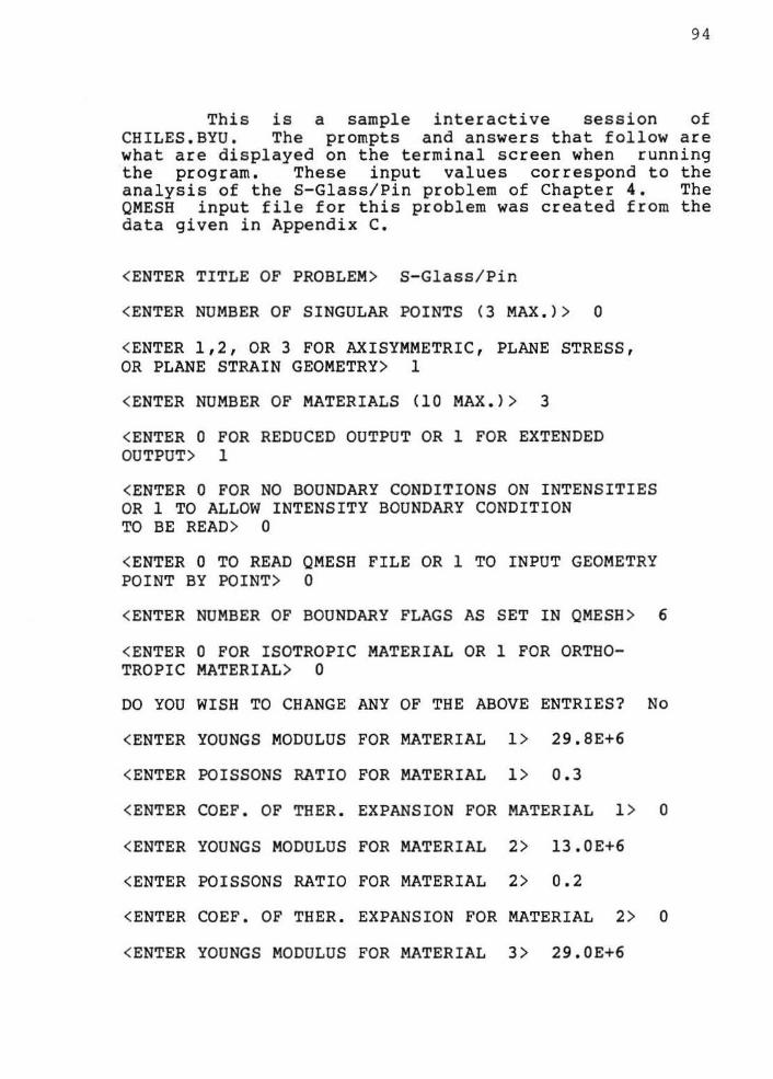
9 4
This is a sample interactive session of CHILES.BYU. The prompts and answers that follow are what are displayed on the terminal screen when running the program. These input values correspond to the analysis of the S-Glass/Pin problem of Chapter 4. The QMESH input file for this problem was created from the data given in Appendix C.
<ENTER TITLE OF PROBLEM> S-Glass/ Pin
<ENTER NUMBER OF SINGULAR POINTS (3 MAX.)> 0
<ENTER 1,2, OR 3 FOR AXISYMMETRIC, PLANE STRESS, OR PLANE STRAIN GEOMETRY> 1
<ENTER NUMBER OF MATERIALS (10 MAX.)> 3
<ENTER 0 FOR REDUCED OUTPUT OR 1 FOR EXTENDED OUTPUT> 1
<ENTER 0 FOR NO BOUNDARY CONDITIONS ON INTENSITIES OR 1 TO ALLOW INTENSITY BOUNDARY CONDITION TO BE READ> 0
<ENTER 0 TO READ QMESH FILE OR 1 TO INPUT GEOMETRY POINT BY POINT> 0
<ENTER NUMBER OF BOUNDARY FLAGS AS SET IN QMESH>
<ENTER 0 FOR ISOTROPIC MATERIAL OR 1 FOR ORTHO-TROPIC MATERIAL> 0
6
DO YOU WISH TO CHANGE ANY OF THE ABOVE ENTRIES? No
<ENTER YOUNGS MODULUS FOR MATERIAL 1> 29.8E+6
<ENTER POISSONS RATIO FOR MATERIAL 1> 0.3
<ENTER COEF. OF THER. EXPANSION FOR MATERIAL 1 > 0
<ENTER YOUNGS MODULUS FOR MATERIAL 2> 13.0E+6
<ENTER POISSONS RATIO FOR MATERIAL 2> 0.2
<ENTER COEF. OF THER. EXPANSION FOR MATERIAL 2> 0
<ENTER YOUNGS MODULUS FOR MATERIAL 3> 29.0E+6

<ENTER POISSONS RATIO FOR MATERIAL 3 > .294
<ENTER COEF . OF THER. EXPANSION FOR MATERIAL 3 > 0
DO YOU WISH TO CHANGE ANY MATERIAL PROPERTY ENTRIES? No
<SPECIFY QMESH FILE> PIN9.DAT
<ENTER BOUNDARY FLAG NUMBER AS SET IN QMESH > 200
<ENTER BOUNDARY CODE> 1 . 0
<ENTER XR OR PN VALUE OF DISPLACEMENT, FORCE OR NORMAL TRACTION>
<ENTER XZ OR SH VALUE OF DISPLACEMENT , FORCE OR SHEAR TRACTION>
<ENTER BOUNDARY FLAG NUMBER AS SET IN QMESH > 300
<ENTER BOUNDARY CODE> -1
<ENTER XR OF PN VALUE OF DISPLACEMENT, FORCE OR NORMAL TRACTION> 50000.
<ENTER XZ OR SH VALUE OF DISPLACEMENT , FORCE OR SHEAR TRACTION> 50000 .
<ENTER BOUNDARY FLAG NUMBER AS SET IN QMESH > 400
<ENTER BOUNDARY CODE> -1
<ENTER XR OR PN VALUE OF DISPLACEMENT, FORCE OR NORMAL TRACTION> 50000 .
<ENTER XZ OR SH VALUE OF DISPLACEMENT , FORCE OR SHEAR TRACTION> 50000 .
<ENTER BOUNDARY FLAG NUMBER AS SET IN QMESH > 500
<ENTER BOUNDARY CODE > -1
<ENTER XR OF PN VALUE OF DISPLACEMENT, FORCE OR NORMAL TRACTION > 50000 .
<ENTER XZ OR SH VALUE OF DISPLACEMENT , FORCE OR SHEAR TRACTION> 50000.
<ENTER BOUNDARY FLAG NUMBER AS SET IN QMESH > 600
95

<ENTER BOUNDARY CODE> -1
<ENTER XR OF PN VALUE OF DISPLACEMENT, FORCE OR NORMAL TRACTION> 50000.
<ENTER XZ OR SH VALUE OF DISPLACEMENT, FORCE OR SHEAR TRACTION> 50000.
<ENTER BOUNDARY FLAG NUMBER AS SET IN QMESH> 700
<ENTER BOUNDARY CODE> 2.0
<ENTER XR OF PN VALUE OF DISPLACEMENT, FORCE OR NORMAL TRACTION>
<ENTER XZ OR SH VALUE OF DISPLACEMENT, FORCE OR SHEAR TRACTION>
DO YOU
DO YOU
DO YOU
WISH TO MAKE ANY CHANGES? No
WISH TO DEFINE A SINGULAR POINT? No
WISH TO DEFINE A BOUNDARY CODE FOR A NODE? No
<<CHILES IS EXECUTING>>
EXECUTION COMPLETED;
YOUR PRINTED OUTPUT FILE IS CHILES.LIS YOUR PLOT DATA FILE IS CHILES.MOV
SEE YOU AGAIN NEXT TIME
YOUR USER FRIENDLY FINITE ELEMENT PROGRAM
SIGNED,
CHILES
96
DEVELOPMENT OF A COMPUTER-AIDED ANALYSIS PACKAGE FOR
LINEAR ELASTIC FRACTURE MECHANICS
William E. Warkentin
Department of Civil Engineering
M.S. Degree, April 1983
ABSTRACT
This thesis develps an interactive computer-aided analysis package for solving linear elastic fracture mechanics problems. CHILES 2 (an existing finite element fracture mechanics program) was modified to be interactive. The modified program is named CHILES.BYU and is used in conjunction with QMESH .BYU and MOVIE.BYU to form the total software package . An analysis of glass ceramics and glass ceramic/metal interfaces was performed demonstrating the capabilities of the package.
This study demonstrates the usefulness of an interactive package of computer programs to allow an engineer to rapidly investigate different crack configurations.
COMMITTEE APPROVAL:
~~ ·~ ~y N. Christiansen Department Chairman