Embed Size (px)
Citation preview

DEVELOPMENT AND TESTING OF RETROFIT SOLUTIONS FOR HOLLOW-CORE FLOORS IN EXISTING BUILDINGS
MIKE PARR – University of Canterbury, DR. KEN ELWOOD – University of Auckland, DES BULL – Holmes Consulting, FRANK BUEKER – University of Auckland, DR.
LUCAS HOGAN – University of Auckland, DR. ASHWARYA PURANAM – University of Auckland, DR. RICK HENRY – University of Auckland, DR. NIC BROOKE – Compusoft
Engineering
SUMMARY
The collapse of precast concrete flooring components in Statistics House and varying levels
of damage to precast floor units in many other buildings during the Kaikoura earthquake has
increased concerns about the performance of these elements in earthquakes. While the details
for these floor systems have been improved in new buildings, support conditions for units in
existing buildings designed before 2006 are likely to lead to significant damage and potentially
collapse in design level ground motions.
Buildings with precast floors comprise a large percentage of the commercial building stock in
all New Zealand cities, with likely over 60% of commercial buildings in Wellington falling in this
category. There are increasingly more residential buildings with older precast floor details as
more buildings are being converted from commercial to residential in Wellington CBD. A
Wellington Fault event will undoubtedly lead to multiple floor collapses in numerous buildings
throughout Wellington.
Assessing the likely performance of these floors in an earthquake is a challenge for engineers.
While guidance has recently been developed for the seismic assessment of buildings with
precast floors (so-called Yellow Chapter), engineers will urgently need direction on retrofit
approaches to address vulnerable buildings. In particular, concern has been raised that seat
angles, already provided as a retrofit for several buildings, could potentially lead to unintended
negative moment failures and collapse of hollowcore floors. This research identifies under
what conditions such unintended failure modes may be triggered and provides a retrofit
solution where vulnerability to negative moment failure is identified.
An experimental investigation was directed at issues related to 200 mm deep hollowcore units
(known as loss of seating (LOS) and Negative Moment Failure (NMF)) that could lead to
casualties in earthquakes. A focus was on identifying seating connection details that would
lead to the unfavourable failure mechanisms and validating retrofit options to remediate
existing floors at risk. A previously used retrofit known as the “seating angle retrofit” to avoid
LOS was also examined to determine if it would promote NMF in cases where it was installed
“hard up” against the bottom of the hollowcore unit. It was found that the relative flexibility of
the most commonly used seating angles reduced the severity of NMF promotion. This was a

good outcome as it meant that many existing cases of the retrofit in New Zealand buildings will
not require further remediation. However, it was found that seating connection details with
stiffer seating angle retrofits or strong or short starter bar configurations are prone to NMF.
These cases represent a smaller subset of floors in New Zealand but will require additional
retrofit. Three retrofit strategies were tested to fix NMF prone cases. These were:
• Cutting starter bars at the interface between the hollowcore unit and support beam to release restraint and demand on the unit at the end of the starter bars – where negative moment cracking initiates.
• Post-installing bars into the unit topping to increase the strength of the unit at the critical
section for crack initiation for NMF.
• Lowering the seating angle retrofit by 10 mm to remove the additional restraint it
imposed on the unit.
All of these retrofits proved successful for preventing NMF. The diaphragm weakening side
effects of cutting starter bars means that this retrofit is only appropriate for some areas of a
floor though.
INTRODUCTION
Two types of precast flooring unit have been widely used in New Zealand construction of multi-storey buildings since the early 1980’s. These precast units are called hollowcore and double-tee units and they are seated on beam ledges with an in-situ concrete topping cast on top. Precast floor units are connected to the beams of the structure using continuity reinforcement or “starter bars”, which are cast into the beams and floor topping. The poor performance of some precast flooring units in Wellington multi-storey buildings during the 2016 Kaikoura Earthquake has confirmed the concerns throughout the engineering industry about the safety of these flooring systems for building occupants. An experimental investigation was directed at issues related to hollowcore units, as they were identified as the precast flooring system with the most pressing concerns. 200 mm deep hollowcore (200HC) units were selected for testing because they are the most commonly used size in New Zealand multi-storey buildings. Also, previous investigations have mainly focussed on 300 mm deep hollowcore units – leaving a gap in the body of knowledge and lack of data regarding 200HC. Two of the critical failure mechanisms to avoid with hollowcore units under earthquake loading are known as “loss of seating” (LOS) and “negative moment failure” (NMF). LOS is undesirable because it describes a unit falling off insufficient ledge seating during an earthquake, which compromises the life safety of building occupants on and below the affected floor. NMF is undesirable because it describes cracking and eventual collapse of the unit away from the ledge support – meaning it will also drop onto the floor below, compromising the life safety of building occupants. Hollowcore is known to perform poorly when subjected to negative moment demands (which imposes tension on the top of the unit), because it only has reinforcing steel near the bottom in the form of pre-tensioned strands. This means the unit itself must withstand tension demand at the top of the unit by the tensile capacity of concrete alone - which is relatively small and unreliable. The only steel reinforcing at the top of a hollowcore floor system (beyond the end of the starter bars) is mesh in the topping, which is insufficient for large earthquake demands. A depiction of LOS is displayed in Figure 1 and a depiction of NMF is displayed in Figure 2.

Figure 1: LOS Mechanism (Sourced from Woods, 2008)
The critical parameter determining if LOS will occur is the available seating length. The critical parameters determining if NMF will occur are the seating length, the length of the starter bars and the strength of the starter bars across back face of the hollowcore unit (where the unit ends against the support beam). A longer seating length is beneficial to prevent LOS but provides a more critical case for NMF. The interaction of the strength vs length of the starter bars is particularly important for NMF, because it is a scenario where the strength of one member in the structure needs to be weaker than the rest, thereby acting as a “fuse”; allowing the structure to deform safely in an earthquake. In this case, it is favourable for the “fuse” and damage concentration to occur at the back face of the unit (a crack forming at the interface of the back of the unit and face of the supporting beam; stretching (plastically deforming) the continuity bars). With the crack forming at this interface, the unit remains supported by the seating ledge. However, if the starter bars are too strong across the back face of the unit or too short, the damage will instead be pushed out to the section at the end of the starter bars where there is a sudden drop in floor strength. Unfortunately, a retrofit detail commonly used in the early 2000’s to address LOS has also had the unintended consequence of promoting NMF. This retrofit called the “seating angle retrofit” is a steel angle bolted to the support beam underneath the unit, providing additional seating for the hollowcore unit. This retrofit is shown in Figure 2.
(a) (b)
Figure 2: Promotion of NMF by the Seating Angle Retrofit (Sourced from Jensen, 2006)
The issue with the seating angle retrofit is that it can hasten the onset of NMF when the angle is installed in direct contact or “hard up” against the hollowcore unit soffit (bottom of the unit). In this case, the unit becomes restrained by the angle when it is rotated (as it would be in an earthquake), changing the support reaction (or pivot point) under negative rotation from the end of the ledge further out towards the end of the angle, as shown in Figure 2. This has two undesirable consequences:
• It is effectively a shortening of the starter bars – which as previously mentioned, results
in the Negative Moment Failure (NMF).
• It creates a negative moment peak demand over the end of the angle which is
essentially to say the angle works to “break the back” of the unit. This extends the

length over which the unit is subjected to negative moment demand (meaning tension
at the top of the floor over a longer length away from the support). This is critical,
because if the unit is still being subjected to a large negative moment demand at the
end of the starter bars, the tension capacity of the topping mesh may be insufficient to
prevent crack initiation and propagation through most of the depth of the unit.
Once negative moment cracking occurs and the mesh is snapped, the effective section available to carry load becomes very small and the stiffness of the hollowcore unit decreases greatly. The negative moment crack propagates from the top of the floor at the end of the starter bars down to the depth of the prestressed strands as shown in Figure 1 (b). From there, the crack continues horizontally along the web, at the height of the prestressed strands, until it reaches near the edge of the ledge or angle support. Under repeated cyclic earthquake loading or even gravity loading, sudden collapse of the unit is a high likelihood at this stage, because the entire floor is primarily being held up only by dowel action of the prestressing strands that cross the main crack in the bottom of the unit, at the support. Multiple tests were required to determine how each mechanism forms: the NMF and the more favourable mechanism of cracking at the back face of the unit over the support ledge. As part of this testing programme, the testing of retrofits to remedy the NMF cases was done. To accomplish this, the single unit testing method used previously by University of Canterbury and University of Auckland researchers was employed. This method used a hollowcore unit supported on one end by a beam segment with the desired ledge seating connection for testing and supported on the other end by a vertically oriented actuator. An additional horizontal actuator attached to the end of the hollowcore unit was also used to impose axial tension on the unit for one test case. This applied axial/longitudinal tension was used where it was appropriate to account for beam elongation (a process through which concrete beams stretch during earthquakes, pushing the hollowcore ledge supports apart). This setup is displayed in Figure 3.
Figure 3: Single Unit Test Layout
The vertical actuator was used to impose rotational demands on the beam-hollowcore seating connection by rotating the hollowcore unit. Downward rotation of the unit (causing negative moment in the unit) is recorded as negative drift and upward rotation is recorded as positive drift.
4000
200

OBJECTIVES
There are two key objectives to this research. These are:
• Identify the seating connection details which lead to Negative Moment Failure (NMF)
under earthquake loading. Ideally, determine the conditions that cause the preferred
cracking at the interface between the back face of the unit and front face of the
supporting beam, over that of NMF.
• Provide initial verification for retrofit strategies to fix seating details identified as being
prone to NMF.
SPECIMEN LAYOUTS
The general layout of the seating connection details is displayed in Figure 4 and Figure 5 and the specific details and objectives for each specimen are listed in Table 1. The layout of a post-installed bar retrofit is shown in Figure 4 including a depiction of the designed strut-and-tie solution.
(a) (b)
Figure 4: Plan View of General Specimen Seating Connection Layout (a) and Post-Installed Bar Retrofit Layout with Strut-and-Tie Solution (b)
Figure 5: Elevation of General Specimen Seating Connection Layout

Table 1: Testing Matrix for Auckland Single Unit Hollowcore Experiments
Test Set One – Existing Cases
Test Case Starter Bar Spacing, Angle, Saw cut? Expected Failure Objectives Results
1 - Unretrofitted, uncracked section
400 mm c/c, None, No LOS or cracking at the unit back face
Control case to display either no critical failure or LOS issue.
No Critical Failure – Crack opened at the back face of the unit. Large amount of remaining seating after cycling.
2 - 150 mm angle (flexible), uncracked section
400 mm c/c, Flexible, No
NMF Display NMF caused by an angle.
No Critical Failure - Crack opened at the back face of the unit. No negative moment cracks progressed into the unit.
3 - 150 mm angle (flexible), cracked section at the end of the starter bars
400 mm c/c, Flexible, 30 mm deep saw cut
NMF Display NMF caused by an angle for a cracked section.
No Critical Failure – Crack opened at back face of the unit. Negative moment cracking progressed a short way into the unit.
4 - 150 mm angle (stiffened), cracked section at the end of the starter bars
400 mm c/c, Stiff, 30 mm deep saw cut
NMF Display NMF caused by a stiff angle for a cracked section.
Critical NMF – negative moment cracking appeared at -1.0% drift, large loss of stiffness and 3 mm vertical crack offset at -1.8% drift and complete loss of stiffness at -2.25% drift.
Test Set Two – Retrofit Cases
Test Case Starters Bar Spacing, Angle, Saw Cut?
Desired Mechanism Objectives Results
5 - 150 mm angle (stiffened), 2 x 1.4 m long post-installed bar retrofit, 4 starter bars, cracked section at the end of the starter bars
300 mm c/c, Stiff, 30 mm deep saw cut
Cracking at the unit back face
Display how reducing the strength drop-off at the end of starters prevents NM failure.
Cracking at the unit back face, no critical failure – negative moment cracking was held closed by the retrofit bars. Secondary cracking developed in the top of the unit similar to a beam plastic hinge. Success.
6 - 150 mm angle (stiffened) placed with a 10 mm gap below the unit soffit, cracked section at the end of the starter bars, elongation tension applied, 30 mm ledge seating
400 mm c/c, Stiff and offset by 10 mm, 30 mm deep saw cut
LOS and unit caught by the angle
Display how removing angle restraint avoids NM failure and tests if there are issues with the unit landing on the angle.
LOS and unit caught by the angle, no critical failure – no issues with the unit landing on the angle or any damage causing the unit to crack and drop beyond the end of the angle. Success.

RESULTS
In the reporting of results, negative (pushing the unit down) and positive drift directions are reversed in load-displacement plots. This is done for clarity, as the critical results for these tests are in the negative drift ranges and the shapes of the hysteresis curves can be more easily interpreted in this configuration.
Test 1, 2 and 3
The first test was set-up as a control case to display the performance of the hollowcore seating connection layout without the addition of any angle or other alterations. Tests 2 and 3 used an unstiffened steel angle seating retrofit to check if the retrofit would push the failure mechanism to NMF. The only difference between Test 2 and 3 was the addition of a crack initiator at the end of the starter bars for specimen 3, as it was considered unreliable to depend on the uncracked properties of the topping to prevent NMF. As shown in Figure 6 and 7, none of these specimens displayed NMF. The primary failure mechanism for all three was a crack opening at the back face of the unit. The effect of the angle was found to be less severe than initially anticipated due to its relative flexibility. It did still increase restraint on the unit though, as seen in Figure 6(b). The stiffness of the system was higher with an angle retrofit up until crack initiation at the back face of the unit occurred leading to a sudden loss of strength. The stiffness of the connection beyond yield of the starter bars in the retrofitted cases was also greater due to the increased restraint. This led to more cracking in the topping compared to the unretrofitted case as displayed in Figure 8, but it did not initiate a critical negative moment crack.
(a) (b)
Figure 6: Test 1 Cyclic Load-Drift Plot (a) and Test 1-3 Monotonic Load-Drift Plot Comparisons
(a) (b)
Figure 7: Specimen 1 Residual Crack After ±4.5% Drift (a), Specimen 2 at -2.75% Drift (b)…

(c) (d)
Figure 8: Specimen 3 at -3.5% Drift (c) and Specimen 3 Topping With Saw-Cut (d)
Test 4
Specimen 4 used the same configuration as Specimen 3 except for the addition of five 12 mm thick stiffeners for the angle retrofit. This relatively extreme case for angle stiffness was used to further investigate the effect of angle retrofit stiffness on the performance of the seating connection while aiming to avoid NMF. Initial cracking occurred at the back-face of the unit at approximately -0.45% drift displacement. This caused an instant loss of stiffness and the unit dropped to -0.6% drift before picking up load again. Negative moment cracking occurred at -1.0% drift displacement. At this stage, the crack at the back face of the unit had opened to approximately 2 mm wide. The negative moment crack did not appear during loading, instead forming approximately 30 seconds after loading stopped. A loud cracking was heard and the unit lost stiffness, increasing the drift to -1.6% instantaneously. The unit at this stage of loading is displayed in Figure 9(b). This result was useful, because it showed that for negative moment cracking to occur, the crack at the back face of the unit needed to open first to sufficiently stress the starter bars to cause NMF. Note the peak load sustained by the seating connection before the sudden failure initiated was less than half of what was observed for the flexible angle cases, as shown in Figure 9(a). This suggests that angle retrofits much more flexible than used in this configuration but stiffer than a Grade 300 12x150x150 equal angle retrofit would also initiate NMF. This will require further investigation in parametric analyses. After this point, loading was continued up to -1.75% drift where it was confirmed that all additional deformation was now occurring at the negative moment crack instead of the unit back-face crack. The specimen was then returned to 0% displacement and a cyclic load protocol of was started. In the first 2.0% drift cycle, the negative moment crack had a sudden extension at -1.8% drift causing the unit to drop instantly to -2.15% drift, which is displayed in Figure 9(a) and (c). At this stage the crack reached the depth of the prestress strands and propagated along them half way to the angle support. A vertical offset of 3 mm was observed at the top of the unit across the NMF crack (initiated by the saw cut). This vertical offset can be considered failure of the unit. In the 3.0% drift cycle, the unit reached -2.25% drift before complete loss of stiffness occurred and the actuator supported end dropped. The wires of the topping mesh were heard snapping one after another as this occurred. The unit would have landed on the floor at the actuator end but was caught by dunnage placed under the unit near the actuator to avoid this. It was caught at -4.25% drift which is shown in Figure 9(a) and (d). Further cycling displayed that from this point on, the pieces of the unit on each side of the negative moment crack were completely separated and the unit was only being supported as a pinned connection by dowel action of the tension strands as shown in Figure 9(a) and (e).

(a)
(b) (c)
(d) (e)
Figure 9: Test 4 Load-Drift Plot (a), Specimen 4 at -1.6% Drift (Directly After NM Crack Initiation at -1.0% Drift) (b), at -2.0% Drift (Crack Propagation Along Strands) (c), at -4.25% Drift (After Complete Loss of Stiffness upon reaching -2.25% Drift) (d) and at -6.0% Drift (e)
Test 5
Specimen 5 was used to test a potential retrofit strategy of installing two 1.4 m long HD12 bars into the topping along the critical section for NMF, as shown in Figure 4 and Figure 10, to prevent the NMF triggered in Test 4. Note, it is important for this retrofit that the post-installed bars do not cross the interface between the unit back face and the support beam front face. The retrofit performed well and prevented negative moment failure up to the monotonic limit of -3.5% drift and then through a set of cyclic loading up to -6% drift. Many cracks formed in the topping and progressed into the unit, but none went beyond half the depth of the unit. Instead,
(b) (c) (d)
(e)
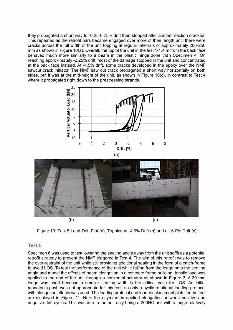
they propagated a short way for 0.25-0.75% drift then stopped after another section cracked. This repeated as the retrofit bars became engaged over more of their length until there were cracks across the full width of the unit topping at regular intervals of approximately 200-250 mm as shown in Figure 10(a). Overall, the top of the unit in the first 1-1.4 m from the back face behaved much more similarly to a beam in the plastic hinge zone than Specimen 4. On reaching approximately -2.25% drift, most of the damage stopped in the unit and concentrated at the back face instead. At -4.5% drift, some cracks developed in the epoxy over the NMF sawcut crack initiator. The NMF saw cut crack propagated a short way horizontally on both sides, but it was at the mid-height of the unit, as shown in Figure 10(c), in contrast to Test 4 where it propagated right down to the prestressing strands.
(a)
(b) (c)
Figure 10: Test 5 Load-Drift Plot (a), Topping at -4.5% Drift (b) and at -6.0% Drift (c)
Test 6
Specimen 6 was used to test lowering the seating angle away from the unit soffit as a potential retrofit strategy to prevent the NMF triggered in Test 4. The aim of this retrofit was to remove the over-restraint of the unit while still providing additional seating in the form of a catch-frame to avoid LOS. To test the performance of the unit while falling from the ledge onto the seating angle and model the effects of beam elongation in a concrete frame building, tensile load was applied to the end of the unit through a horizontal actuator as shown in Figure 3. A 30 mm ledge was used because a smaller seating width is the critical case for LOS. An initial monotonic push was not appropriate for this test, so only a cyclic rotational loading protocol with elongation effects was used. The loading protocol and load-displacement plots for the test are displayed in Figure 11. Note the asymmetric applied elongation between positive and negative drift cycles. This was due to the unit only being a 200HC unit with a ledge relatively

high on the support beam. This meant the rotation component to LOS about the centroid of the support beam was more critical for positive drifts than negative. Initial cracking of the unit occurred as a full depth hairline crack at the back face of the unit in the first 0.5% drift cycle. Damage remained concentrated at this crack for the rest of the test. No further interesting damage occurred until the second 2.0% drift cycle. As the unit reached -2.0% drift, the middle starter bar ruptured, and the reaction and restraint of the seating connection greatly reduced as seen in Figure 11. In the first 3.0% drift cycle, the unit began dropping off the ledge support on the eastern side during the first +3.0% cycle as shown in Figure 12(a). The outer starter bar on the eastern side of the specimen also ruptured as the unit was approaching -3.0% drift. Only having one remaining point of connection between the hollowcore unit and beam section (that was off-centre in plan) changed the structural system of the experiment. To allow the completion of the test up to a cycle at 4.5% drift with complete LOS of the unit, the final starter bar was manually cut. The 4.5% drift cycle was completed with the unit completely supported by the angle. There was no indication of restraint against the beam ledge or cracking occurring away from the support as shown in Figure 12(b).
(a) (b)
Figure 11: Test 6 Loading Protocol (a) and Horizontal Load-Displacement Plot (b)
(a) (b)
Figure 12: Specimen 6 at +3.0% Drift (25 mm Pull-Off) (a) and at +4.5% Drift (b)
CONCLUSIONS AND KEY FINDINGS
• Stiffness of the seating angle retrofit was found to be a major determining factor for
whether NMF was triggered or not. The commonly used 150x150x12 steel equal angle
was found to be more flexible than expected, causing a lower amount of restraint to be
applied to the unit than anticipated.
• Most steel angle seating retrofits currently installed hard up again hollowcore unit soffits
in New Zealand buildings would be considered “flexible” by the findings of this

investigation. This is a positive outcome, because it means that many existing seating
angle retrofit cases should not cause undesirable performance (triggering a NMF) and
become a danger to the occupants, and therefore such angles do not require any
further remediation. However, for Grade 500 starter bar reinforcing layouts this only
applies to when the starters are 600 mm or longer and have a unit back face tensile
strength equivalent or lower than that of HD12s spaced at 400 mm c/c. The most
common starter bar layout uses a spacing of 300 mm c/c – which would require some
form of additional retrofit (against NMF) even for a flexible angle case.
• Drilled holes at the back face of the unit is not a required retrofit strategy for NMF
(Jensen 2008) – the natural progression of damage towards an NMF requires a crack
to open at the back face of the unit anyway - to engage the starter bar strength.
Therefore, this retrofit option makes no valuable changes to the structural system.
• Cutting starter bars across the back face of the hollowcore unit is a valid retrofit strategy
for NMF as it reduces restraint and therefore negative moment demand at the end of
the unit and end of the starter bars. However, it also has the side effect of reducing the
strength of the floor diaphragm. This makes it an appropriate strategy for the corners
of a floor plan or in the middle of support beams where the diaphragm strut-and-tie
design is unlikely to be relying on the topping reinforcement to act as critical floor ties.
• The post-installed epoxied bar retrofit is a valid retrofit strategy for NMF and has the
added benefit of maintaining the designed diaphragm load path. This makes the retrofit
appropriate for areas of the floor seating near intermediate columns on the exterior of
the building, or the columns within the interior of the floor plan, of which all are likely to
be designed as major tie anchor points in the floor diaphragm strut-and-tie design.
• Lowering the seating angle retrofit 10 mm under the unit soffit is a valid retrofit strategy, as it removes the effect of this retrofit detail promoting NMF and instead acts as a catch-frame for the falling floor. Under the test conditions, there was no indication of an issue with the unit landing on the angle once LOS occurred. However, it is recommended for new angle installations that a lowered seating angle with a compressible material infill between the angle and unit soffit is used. This would provide minimal restraint to the unit but also ensure that no impact loading occurs during an earthquake where vertical accelerations could be substantial.
• It is expected that where Grade 500 starter bars have been used for continuity
reinforcement; most of these reinforcing bars around the floor perimeters will have
ruptured by approximately 2.5-3.0% drift demand because of beam elongation in long
duration earthquakes. This drift range is around the ultimate limit state (ULS) design
level earthquake displacement demands.
• For long duration ULS design level earthquakes, the strut-and-tie diaphragm design
solution will likely be destroyed for much of the later cycles. Future research will
investigate how this could impact building performance in earthquakes.
REFERENCES
Jensen, J. (2006). The Seismic Behaviour of Existing Hollowcore Seating Connections Pre and Post Retrofit. Christchurch: University of Canterbury.
Woods, L. (2008). The Significance of Negative Bending Moments in the Seismic Performance of Hollow-Core Flooring. Christchurch: University of Canterbury.