Embed Size (px)
Citation preview
Development and Testing of Cavitation Jet Erosion Test Rig
Abhinav Pandey, Abhishek Jain & Vipul AroraT-11
B.Tech, Mechanical EngineeringIIT Roorkee

Outline of the Presentation
• Cavitation (what it is, why so critical etc..)• Present available testing methods (discuss each of them in detail)• Short comings of available methods• What we are going to do (how our work is overcoming those disadvantages)• Complete discussion (theoretical) of our system (mostly from ASTM)• Design of the setup• Detailed description of each component (what were the design criteria, available
option, why the particular selection is made) Complete description about the working of components along with specification.
• Assembly of the components• Design of experiment• Calibration• Testing• Discussion of results• Conclusions• Future work• References• Bibliography
Dept. of Mechanical & Industrial Engg.
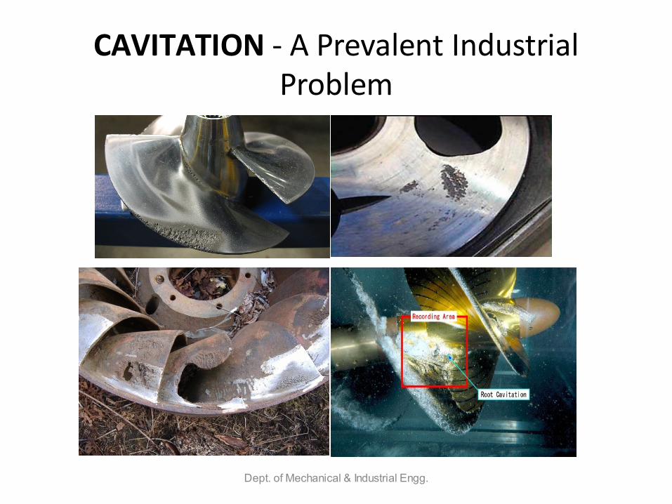
CAVITATION - A Prevalent Industrial Problem
Dept. of Mechanical & Industrial Engg.
Cavitation Damage
• Performance loss in:• Pumps • Hydraulic turbines• Valves• Bearings• Diesel Engine Cylinder Liners• Ship Propellers• Hydraulic Dynamometers and Couplings
• Unbalanced rotational forces causing harmful vibrations.
Dept. of Mechanical & Industrial Engg.

Dept. of Mechanical & Industrial Engg.
Advantages of G-134• Precise simulation of cavitation behavior, and thus of erosion due
to collapse of cavities.
• A satisfactory alternative for the more traditional cavitation tunnel technique.
• Precisely shaped specimen are not required, a basic requirement of G-32.
• Testing process can be accelerated or slowed down, if conducted at constant cavitation number.
• Also facilitates the comparison of erosion behavior of various liquids, in addition to grading materials.
Dept. of Mechanical & Industrial Engg.

OUR APPROACH
Dept. of Mechanical & Industrial Engg.
Erosion by a Cavitating Liquid Jet
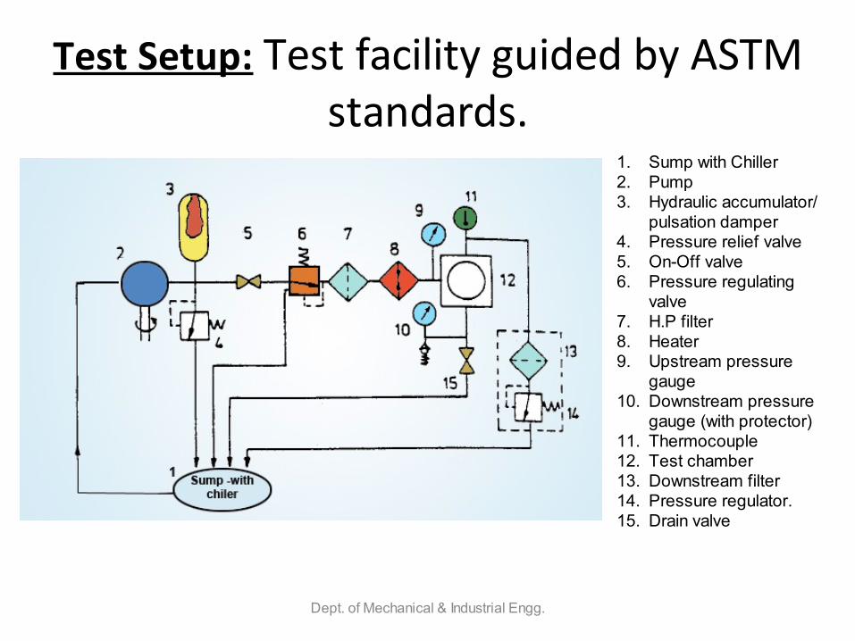
Test Setup: Test facility guided by ASTM standards.
Dept. of Mechanical & Industrial Engg.
1. Sump with Chiller2. Pump3. Hydraulic accumulator/
pulsation damper4. Pressure relief valve5. On-Off valve6. Pressure regulating
valve7. H.P filter8. Heater9. Upstream pressure
gauge10. Downstream pressure
gauge (with protector)11. Thermocouple12. Test chamber13. Downstream filter14. Pressure regulator.15. Drain valve

Test Chamber
Dept. of Mechanical & Industrial Engg.
December
• Design Calculations for various components
• Order and procurement of :– Seamless Tubing– Connectors and fittings– Hose pipes– Inline Filters– Downstream Pressure regulation Valve– Bleed valve
MIED, IIT RoorkeeFebruary 11, 2010
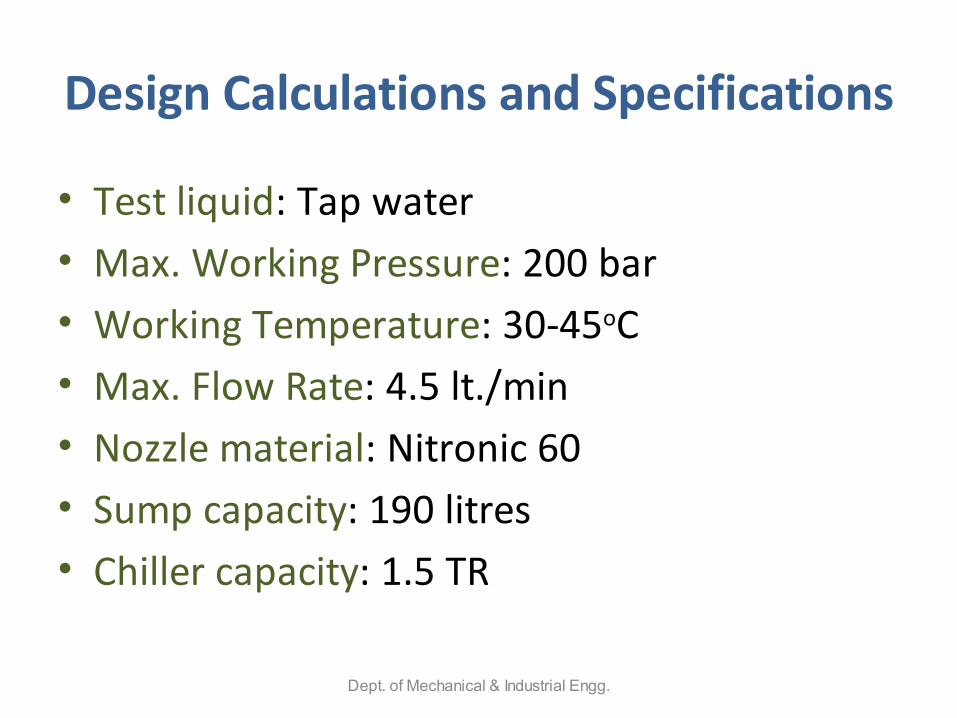
Design Calculations and Specifications
• Test liquid: Tap water• Max. Working Pressure: 200 bar• Working Temperature: 30-45oC• Max. Flow Rate: 4.5 lt./min• Nozzle material: Nitronic 60• Sump capacity: 190 litres• Chiller capacity: 1.5 TR
Dept. of Mechanical & Industrial Engg.
Design: Sump Tank
• Capacity: 190 lt.
• Dimensions: 620x620x500 mm
• Material: Stainless Steel 304
• 3 mm thick SS sheet
• Argon weld at joints; leakage proof
• Double baffle design: To reduce turbulence
• Provision for Air Tight arrangement with gasket and lid
• Arrangement for level indicator
February 11, 2010 MIED, IIT Roorkee

Design: Chilling Arrangement
• Max. Flow rate: 4.5 lt/min
• Max. Inlet fluid temperature: 42 0C (approx.)
• Outlet fluid temperature: 30 0C (approx)
• Cooling Capacity: 1.5 TR
• Compact unit
February 11, 2010 MIED, IIT Roorkee

Januaryo Procurement of:
o Pressure gaugeso Ball Valve, Upstream Pressure Regulatoro Material for development of chiller- compressor, condenser, etc
o Design of the components & test-rig in SolidWorks
o Development of:o Mountings and Supportso Sump tanko Motor Pump coupling
MIED, IIT RoorkeeFebruary 11, 2010
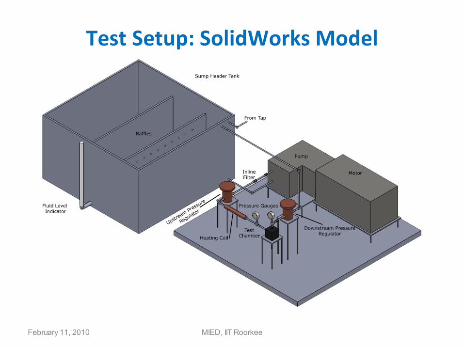
Test Setup: SolidWorks Model
MIED, IIT RoorkeeFebruary 11, 2010

Sump/Header Tank
February 11, 2010 MIED, IIT Roorkee

February 11, 2010 MIED, IIT Roorkee

February 11, 2010 MIED, IIT Roorkee

February• Development of chiller arrangement for sump tank
• Order of Nozzle material (why nitronic-60 ?)
• Modification of Test Chamber (Nozzles and Jet Deflector)
• Assembly of the components
MIED, IIT RoorkeeFebruary 11, 2010
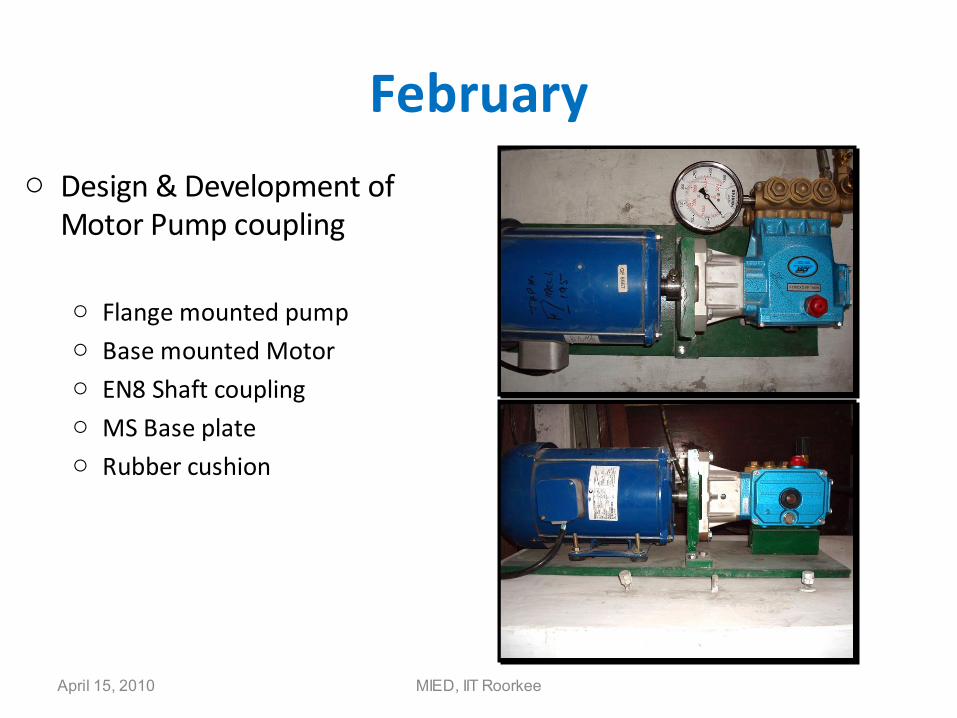
Februaryo Design & Development of
Motor Pump coupling
o Flange mounted pumpo Base mounted Motoro EN8 Shaft couplingo MS Base plateo Rubber cushion
MIED, IIT RoorkeeApril 15, 2010

February
MIED, IIT RoorkeeApril 15, 2010
Development of Chilling unit

Marcho Design of the mountings and supports
o Custom design for each component/equipmento Design Criteria:
o Common baseline for piping/tubingo Minimum number of joints and bendso Sturdy and reliable supports & least vibrations
MIED, IIT RoorkeeApril 15, 2010
March
MIED, IIT RoorkeeApril 15, 2010
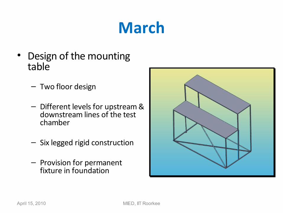
• Design of the mounting table
– Two floor design
– Different levels for upstream & downstream lines of the test chamber
– Six legged rigid construction
– Provision for permanent fixture in foundation

Marcho Development of the mountings and supports
o MS bodyo Chrome Plated
MIED, IIT RoorkeeApril 15, 2010
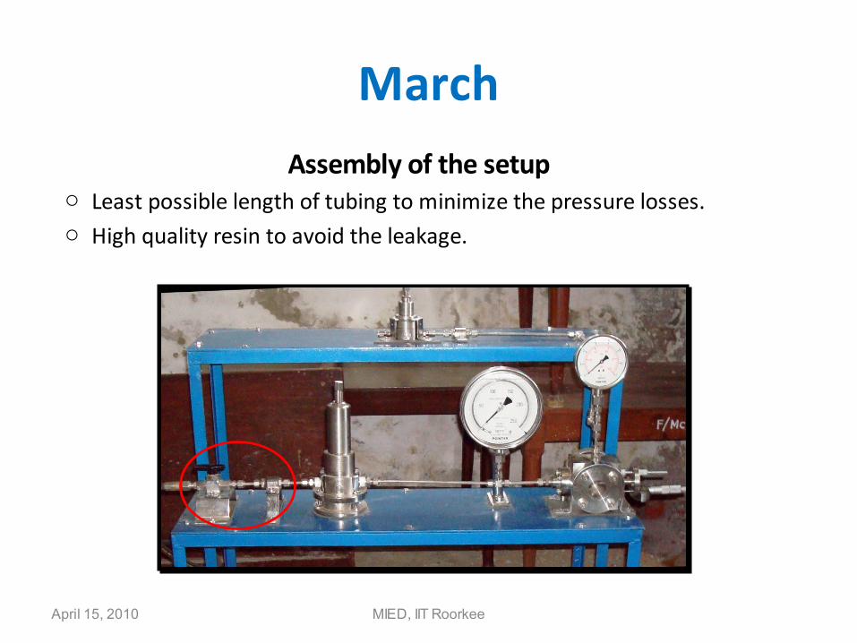
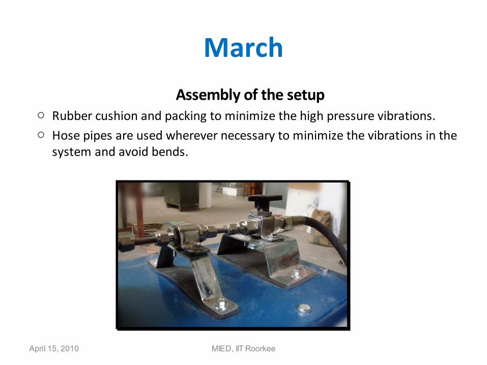
MarchAssembly of the setup
o Least possible length of tubing to minimize the pressure losses.o High quality resin to avoid the leakage.
MIED, IIT RoorkeeApril 15, 2010
March
Assembly of the setupo Rubber cushion and packing to minimize the high pressure vibrations.o Hose pipes are used wherever necessary to minimize the vibrations in the
system and avoid bends.
MIED, IIT RoorkeeApril 15, 2010

April
MIED, IIT RoorkeeApril 15, 2010
• Development of foundation– 6” high foundation for sturdiness of the system

April
MIED, IIT RoorkeeApril 15, 2010
• Troubleshooting– Increment on the inlet hose to ensure sufficient
supply to pump & to avoid cavitation– Modification in the unloader assembly to suit the
experimental requirements– Cleaning of the choked filters, because of the use of
tap water– Arrangement of distilled water
• Installed the distilled water plant in IC engine lab

May – Solving unforeseen problems
MIED, IIT RoorkeeApril 15, 2010
• Modification of the Test setup– To further minimize the connectors– To easily adjust the upstream and downstream pressures– Now the setup can be run in both the modes as describes
in ASTM G-134– A new and easy method has been devised.
• Insulation to the sump tank • Modification of the nozzles (now available in 0.4, 0.6,
0.8, 1.0 mm dia)• Preparation of test specimens

May
MIED, IIT RoorkeeApril 15, 2010
• Design of Experiment• Important considerations before beginning the experimentation
• Check oil level in the pump crankcase. • Check the water level in the tank.• Ensure proper ventilation for the drive unit (Motor-Pump set).• Make sure all valves are open (to avoid deadhead overpressure condition).• Make sure all filters (including that inside the pump) are not clogged.• Perform a complete test on a standard reference material.
• Standard Experimentation Procedure • Insert a dummy specimen inside the test chamber.• Set the standoff distance based on the desired cavitation number.• Start the system with the unloader backed off to the lowest pressure setting (counterclockwise direction).• Set and adjust the unloader pressure. (using the pressure reading at the pressure gauge on the manifold and not at the gun or nozzle)• Allow the system to stabilize and make sure that the temperature at the nozzle inlet is around 35oC.
• Ensure that the test specimen is not damaged merely by the stagnation pressure developed by the jet.• Switch off the ball valve and remove the dummy specimen.• Clean and weigh the test specimen till identical balance readings are obtained; and insert it in the test chamber.• Switch on the ball valve and remove all air from the hydraulic circuit.• Periodically switch off the ball valve, and remove the specimen.• Carefully clean the specimen using an ultrasonic bath.• Dry the specimen, and determine its mass on a balance.• Insert this specimen back into the test chamber.• Plot the mass loss against time as the test proceeds.• Repeat steps 9-14 till until the cumulative erosion rate reaches a maximum and starts to diminish.

OutcomesStudy of various parameters on cavitation erosion
under controlled environment.
Estimation of relative erosion of materials due to cavitation.
Comparison of erosion wear due to different liquids.
First state of art facility in an IITs & fifth in the world, thus of great help to industrial research.
Dept. of Mechanical & Industrial Engg.
![Evaluation of cavitation erosion resistance of Al-Si ...€¦ · cavitation erosion models based on bulk mechanical properties [11-13] were performed in order to predict the erosion](https://img.pdfslide.us/doc/110x75/602fbc102d0fbb7b2944c54a/evaluation-of-cavitation-erosion-resistance-of-al-si-cavitation-erosion-models.jpg)


![Experimental Research on Cavitation Erosion Detection Based on … · 2012-10-09 · estimate cavitation erosion by observing the removal of the paint [3]. They detect cavitation](https://img.pdfslide.us/doc/110x75/5e93bba127dcb37304714469/experimental-research-on-cavitation-erosion-detection-based-on-2012-10-09-estimate.jpg)