Embed Size (px)
Citation preview

Study of the unified control system of the magnets
in the KEKB/PF-AR accelerators
Tatsuro Nakamura
DOCTOR OF PHILOSOPHY
Department of Accelerator Science
School of High Energy Accelerator Science
The Graduate University for Advanced Studies
2011

Abstract KEKB is a double-ring, asymmetric-energy, electron-positron collider, which is
pursuing luminosity frontier. In order to improve its luminosity, commissioning has been continued incessantly. Because various machine tunings are frequently necessary during the commissioning, the control system is required to be highly responsive and flexible. Especially for the magnets and magnet power supplies, which define optics of the accelerators, the efficiency and flexibility of the control system are essentially important.
To achieve these requirements the design and the construction of the control system of the magnet power supplies have been carried out with the following view points. The most important point is the unified treatment of the magnet power supplies. KEKB has wide variety of the magnet power supplies, from the large power supplies for the main bending magnets to the small power supplies for the steering magnets. The bending magnets, quadrupole magnets, sextupole magnets and steering magnets require different type of power supplies and are operated in the different manner. The magnet can be iron core or air core, superconducting or normal conducting, with or without auxiliary windings, and so on. There are many different types of the magnet power supplies, in the scale, in the regulation scheme, bipolar or unipolar, with or without pole changer, and so on. Although such differences exist, focusing on the common properties of the magnet power supplies, the hardware of the interface and the software of the control system have been designed not separately for each type but designed as universal for the all types as possible.
Another important point is reliability. Although resources of the budget and the man power to construct KEKB have been limited, it has been required to keep the control system reliable. Not only in the construction phase but also in the maintenance phase, reliability should be considered. In order to maintain reliability in such conditions, the design strategy adapted is simplification. Especially it is important how to simplify the interface to the magnet power supply with the control computer. It greatly influences the reliability of the control system. In the previous, TRISTAN, control system CAMAC was adopted as the standard interface. Between the CAMAC module and the magnet power supply there were wired signal lines for each signal one by one. If KEKB adopted the same scheme, the amount of wires could be huge because the number of magnet power supplies in KEKB is large, more than double. In KEKB, instead of the parallel wiring, one serial line has been introduced for a magnet power supply. All signals are exchanged through the single serial line.
2

Thus, considering unification and simplification as the important principles, the magnet power supply control system has been developed. There are two major tasks in the development. One is the development of the interface between the control computers and the magnet power supplies. The other is the development of the control software. KEKB control system has adopted EPICS (Experimental Physics and Industrial Control System) as the core software framework. And two types of computers have been installed. One is IOC (Input/Output Controller), which directly controls the equipments through its own hardware connection to the equipments. The other is OPI (Operator Interface), which runs various high level applications like operator interface.
The synchronous operation of multiple magnet power supplies is required in order to change optics without loosing stored beams. For this purpose, the synchronous setting has been designed that the tracking data are calculated in the IOC and sent to the magnet power supply beforehand and then the synchronous start signal triggers the synchronous tacking. In this method the magnet power supply is required to store the array data for the tracking and to set them in sequence with the interval clock. Although it requires some intelligence in the magnet power supply, total system can be simplified and flexible operation is possible. ARCNET (Attached Resource Computer NETwork) has been adopted as the serial interface. It supports relatively long packet and communication speed is enough for our purpose. The twisted-pair cable with RS485 type differential driver has been chosen as the media of ARCNET. This configuration allows multi-drop wiring. The synchronous start signal is also delivered by the cable combined with ARCNET. Thus, the simplification of the wirings has been achieved. For the implementation of the ARCNET interface, the PSICM (Power Supply Interface Controller Module) has been developed. It is the plug-in module in the magnet power supply and has an ARCNET interface and a microcomputer with the control software (firmware). PSICM has been designed to be universal for any type of the power supplies. All of the magnet power supplies can be controlled in single manner using PSICM.
In the development of the control software, the magnet power supplies have been treated in unified manner. Among the different types of the magnets and the power supplies, the common features are abstracted. Major functions incorporated in the IOC are followings.
(1) parameter conversion from abstracted magnetic field strength to the current (2) regular setting sequences to reduce the magnetic hysteresis problem (3) synchronous and asynchronous operations for the current setting Although the magnet power supply control system has been originally designed for
the KEKB, because of its universal design, it has been also well applied to the PF-AR
3

magnet control system. PF-AR has been upgraded in 2001. At that time its control system has been renewed using the same way as KEKB. PSICM can be used for PF-AR without any modifications. Most of the control software for KEKB can be also applied for PF-AR. In addition for PF-AR, the pattern operation of the acceleration has been developed based on the same mechanism of the synchronous operation. The tracking pattern of the acceleration can be flexibly configured.
As the unification has been implemented in the IOC layer, the magnet power supply can be treated as the abstracted object independent of the hardware in the OPI layer. Such abstraction has reduced the load of the development of the user application programs. Thus, during a decade of the commissioning of the KEKB accelerators, many application programs have been developed and have contributed to the tuning up and improvement of the accelerators continuously.
4

Contents 1. Introduction.....................................................................................................................8 1-1. Motivation and approach of the study ........................................................................8 1-2. Composition of the thesis.............................................................................................9 2. KEKB magnet power supplies and control system...................................................... 11 2-1. The magnets and the magnet power supplies for the KEKB accelerators .............. 11 2-2. EPICS .........................................................................................................................12 2-2-1. IOC database...........................................................................................................14 2-2-2. Channel Access........................................................................................................14 2-3. KEKB accelerator control system..............................................................................15 2-3-1. IOC in KEKB ..........................................................................................................16 2-3-2. Control network ......................................................................................................18 2-3-3. OPI layer .................................................................................................................18 3. Development of the interface to the magnet power supply.........................................20 3-1. Prerequisites of the design of the interface ..............................................................20 3-2. Consideration of the CAMAC system of TRISTAN ..................................................20 3-3. Serial communication for the interface.....................................................................21 3-4. Synchronous operation of the multiple magnet power supplies ..............................22 3-4-1. The required specifications of the synchronous setting ........................................22 3-4-2. Implementation of the synchronous setting ..........................................................24 3-5. Delivery system of the synchronous start signal......................................................26 3-5-1. Event timing system...............................................................................................26 3-5-2. Delivery of the synchronous start signal from the IOC to the magnet power supply.................................................................................................................................27 3-6. PSICM ........................................................................................................................28 3-7. ARCNET interface VME module for the magnet power supply...............................30 3-8. ARCNET hub for the magnet power supply .............................................................32 3-9. Entire configuration of the magnet power supply control system ...........................33 3-9-1. Current monitor system of the magnet power supply...........................................34 3-9-2. Interlock signal from the magnet...........................................................................35 4. Development of the control software............................................................................36 4-1. 3-layers scheme of the distributed control system ...................................................36
5

4-1-1. Software of the PSICM layer..................................................................................36 4-1-2. Software of the IOC layer .......................................................................................37 4-1-3. Software of the OPI layer .......................................................................................39 4-2. Required functions for the magnet power supply control software .........................39 4-3. Control parameter......................................................................................................40 4-3-1. Magnetic field as the control parameter................................................................40 4-3-2. Excitation function..................................................................................................41 4-3-3. Virtual parameter and QCS virtual magnet power supplies ................................43 4-4. Standardization..........................................................................................................44 4-4-1. Direct setting...........................................................................................................44 4-4-2. Sequence setting .....................................................................................................45 4-4-3. Standardize setting.................................................................................................45 4-4-4. Simple standardize setting.....................................................................................46 4-5. Asynchronous setting and Synchronous setting .......................................................47 4-5-1. Asynchronous setting..............................................................................................47 4-5-2. Synchronous setting................................................................................................47 4-5-2-1. Synchronous setting server .................................................................................47 4-5-2-2. Synchronous pole change server .........................................................................50 4-6. Exclusion control for the magnet with auxiliary coils..............................................52 4-7. Implementation of the software on the IOC .............................................................54 5. User application programs for the operation...............................................................57 5-1. Operation panel for the storage rings .......................................................................57 5-2. Operation panel for the injection BT lines................................................................59 5-3. Injection mode switching panel for the BT line ........................................................60 5-4. Optics panel for the storage rings .............................................................................61 5-5. Orbit correction panel for the storage rings..............................................................62 6. PF-AR magnet power supply control system ...............................................................64 6-1. Upgrade of PF-AR ......................................................................................................64 6-2. Treatment of the existing magnet power supplies of PF-AR ...................................65 6-3. Tracking of the acceleration of PF-AR ......................................................................65 6-4. Control system of the injection BT line of PF-AR.....................................................67 7. Discussion......................................................................................................................68 7-1. Simplification .............................................................................................................68
6

7-2. Unification..................................................................................................................68 7-3. Prerequisite and limit of application of the methodology ........................................69 7-4. Balance between hardware and software .................................................................70 8. Summary .......................................................................................................................72 Acknowledgements............................................................................................................75 References..........................................................................................................................77
7
1. Introduction 1-1. Motivation and approach of the study
KEK B-factory (KEKB) is an asymmetric-energy electron-positron collider. It consists of two storage rings. One is LER (Low Energy Ring), which stores the 3.5GeV/c positron beam, and the other is HER (High Energy Ring), which stores 8GeV/c electron beam. Both beams collide at the Interaction Point (IP) to produce intensive pairs of B meson and anti-B meson. Belle detector is installed at the IP. The B mesons are provided for the various experiments of the elementary particle physics, especially for the experimental studies of the CP violation in B meson decays.
These experiments require large amount of B mesons in order to improve statistical precision. Thus, KEKB has challenged to the aggressive goal that the design luminosity is 1034cm-2s-1, which is one-order of magnitude higher luminosity than ever achieved before. To achieve such high luminosity the commissioning phase of KEKB was expected to be continued for a long time. Indeed the commissioning has been continued during the whole operation period. The operation of KEKB started in 1998. The design luminosity has been achieved in 2003. Even after that the effort to improve the luminosity has been still continued. Finally the luminosity has reached to the twice of the design value in 2009.
Because various machine tunings are frequently necessary during the commissioning, the control system is required to be highly responsive and flexible. Especially for the magnets and magnet power supplies, which define optics of the accelerators, the efficiency and flexibility of the control system are essentially important. The main theme of this thesis is a methodology to design and to construct a control system of the magnet power supplies to achieve these requirements.
In the KEKB, the design and the construction of the control system of the magnet power supplies have been carried out with the following view points. The most important point is the unified treatment of the magnet power supplies. KEKB has wide variety of the magnet power supplies, from the large power supplies for the main bending magnets to the small power supplies for the steering magnets. The bending magnets, quadrupole magnets, sextupole magnets and steering magnets require different type of power supplies and are operated in the different manner. The magnet can be iron core or air core, superconducting or normal conducting, with or without auxiliary windings, and so on. There are many different types of the magnet power supplies, in the scale, in the regulation scheme, bipolar or unipolar, with or without pole
8

changer, and so on. Although such differences exist, focusing on the common properties of the magnet power supplies, the hardware of the interface and the software of the control system have been designed not separately for each type but designed as universal for the all types as possible. It helps accelerator physicist to concentrate on the problems of accelerator physics rather than the detailed difference of the magnetic power supplies during the development of software and accelerator operation.
Another important point is reliability. Although resources of the budget and the man power to construct KEKB have been limited, it has been required to keep the control system reliable. Not only in the construction phase but also in the maintenance phase, reliability should be considered. In order to maintain reliability in such conditions, the design strategy adapted is simplification. Especially it is important how to simplify the interface to the magnet power supply with the control computer. It greatly influences the reliability of the control system. In the previous, TRISTAN, control system CAMAC was adopted as the standard interface. Between the CAMAC module and the magnet power supply there were wired signal lines for each signal one by one. If KEKB adopted the same scheme, the amount of wires could be huge because the number of magnet power supplies in KEKB is large, more than double. In KEKB, instead of the parallel wiring, one serial line has been introduced for a magnet power supply. All signals are exchanged through the single serial line.
Thus, considering unification and simplification as the important principles, the magnet power supply control system has been developed. There are two major tasks in the development. One is the development of the interface between the control computers and the magnet power supplies. The other is the development of the control software. In this thesis the details of these developments are described. The large scale control system like a magnet power supply control system for accelerators tends to be complicated because it involves large diversity of the components and diversity of the required operations. But focusing on the universal features among the diversity, it is possible to reduce the complexity and to construct the control system with good perspective. This thesis shows such methods through describing the process of the development of the KEKB/PF-AR magnet control system. 1-2. Composition of the thesis
In this chapter, the background of this study has been described. And then the approach of the study has been presented. In addition, the composition of the thesis is also presented.
9

In chapter 2, the prerequisites for the system design is reviewed. One is the magnets and the magnet power supplies for the KEKB accelerators. Another is the KEKB control system itself. They are boundary conditions of the study.
In chapter 3, the detailed design and development of the I/O (Input/Output) interface between control computer and the magnet power supply are described. The unified serial I/O interface has been designed, which is universal for any type of magnet power supplies. Specifically ARCNET, which is a token passing field network, has been adopted for the I/O interface. The dedicated protocol has been defined on the ARCNET packet. The I/O interface also includes the synchronous start signal. Not only the specification of the I/O interface has been defined, but also its implementation, named PSICM, has been developed. PSICM is the plug-in module into the magnet power supply and also universal for any type of magnet power supplies. Total configuration of the control system of the magnet power supplies is also described in chapter 3.
In chapter 4, the detailed features of the control software are described. Treating the magnet power supply as an abstracted object in software, it can be handled in unified manner without considering the detailed differences of the hardware in the higher-level application programs. Because the KEKB magnet power supply control system is the distributed control system, the key point of the software design is that how the functions are divided and distributed over the layers. At first this point is discussed. Then each description of the developed software follows. Finally the implementation of the software of the control computer is also described.
In chapter 5, in order to show how the magnet power supply control system has been used in the actual operation of the accelerators, several examples of the higher-level application programs written by users including the author are introduced.
In chapter 6, the PF-AR magnet power supply control system is described. Originally the magnet power supply control system using ARCNET and PSICM has been designed only for KEKB accelerators. Later it has been able to be applied also to the upgrade of the PF-AR. Only by adding some extensions to the software almost all features of the KEKB magnet power supply control system can be shared with the PF-AR system, so that the efficient development has been achieved. The history of the application and the additional features specific to the PF-AR are described in chapter 6.
In chapter 7, discussing its methodology of the system design, more general analysis is shown. Several guidelines to design control system are presented.
In chapter 8, summary of this thesis is described.
10

2. KEKB magnet power supplies and control system
In this chapter, the magnets and the magnet power supplies for the KEKB accelerators are described. The control system is also overviewed. They are the prerequisite for the system design. 2-1. The magnets and the magnet power supplies for the KEKB accelerators
Table 1 shows the numbers of magnets and magnet power supplies in LER and HER. To increase the flexibility of operation and beam tuning, more then 2200 magnet power supplies have been installed for the two storage rings. Among them more than 1700 are small power supplies whose rating electric current is 10A or less. These small power supplies are mainly used for the corrector dipoles. Installing such a large number of corrector magnets and magnet power supplies is the unique characteristic of the KEKB accelerators.
Because KEKB accelerators have been constructed in the reused tunnel of TRISTAN, the power supply rooms and the local control rooms are also the reuse of TRISTAN. The components of the TRISTAN accelerators have been also reused as many as possible. Many magnets have been reused but also many magnets have been newly produced for the KEKB. In contrast almost all magnet power supplies are newly designed and produced. Exceptions are only 8 large power supplies, which are the reuse of the TRISTAN ones.
Table 2 shows the numbers of magnets and magnet power supplies in the beam transport lines (BT), which transport positrons and electrons from Linac to the injection points of LER and HER.
12 power supply buildings are distributed along the tunnel of the storage rings and are named with number from D1 to D12. The magnet power supplies for LER and HER are installed in 8 of them (D2, D3, D5, D6, D8, D9, D11, D12). The magnet power supplies for BT are installed in 3 power supply rooms (CBT, ARS, ARW), which are located in the central control building or PF-AR experiment buildings.
11

Table 1: numbers of magnet power supplies in KEKB rings Numbers of magnets are also shown in parentheses.
LER HER
Bend 28 (168) 24 (136) Steering 555 (555) 527 (527) Quadrupole Normal Quad. 118 (450) 113 (436) Skew Quad. 8 (8) 12 (12) IR-Quad. 2 (2) 4 (4) Sextupole Normal Sx 54 (108) 52 (104) Skew Sx 4(8) 10 (20) Wiggler 4 (146) Auxiliary coil Back-leg 50 35 Aux. Quad. 8 1 Aux. Sx 6 6 Solenoid to sweep photoelectron 596 Special magnet / power supply Lambertson septum 1 (1) 1 (1) QCS 10 (2) BBA (beam based alignment) 2
Total 2231 (2688)
Table 2: numbers of magnet power supplies in KEKB BT lines
Numbers of magnets are also shown in parentheses.
Positron BT line Electron BT line
Bend 16 (58) 18 (65) Steering 50 (50) 45 (45) Quadrupole 53 (61) 53 (60) Back-leg 16 25
Total 276 (339)
2-2. EPICS
12

For constructing the control system of KEKB accelerators, the control system of TRISTAN is not reused. Instead new control system has been developed. As the core software framework of the new control system, EPICS has been adopted.
EPICS (Experimental Physics and Industrial Control System) is the software toolkit to construct control systems for scientific instruments such as accelerators, telescopes and other large experimental apparatuses. EPICS is developed and maintained by international collaboration. Figure 1 shows a typical configuration of the control system using EPICS. In general two types of computers are used in the EPICS control system. One is IOC (Input/Output Controller), the other is OPI (Operator Interface). IOC is the computer which directly controls the equipments through its own hardware connection to the equipments. OPI is the computer which runs various high level applications like operator interface. IOC and OPI are connected each other by LAN (Local Area Network) with IP (Internet Protocol). They constitute a distributed control system, where IOC provides control services, and OPI utilize them as clients. Thus, EPICS is suitable to the network distributed system.
One of the typical IOC is a VME (VERSAmodule Eurocard bus) single board computer. In this case, various types of VME interface boards are often used to connect to the devices. In historical reason VxWorks is often used as OS (Operating System) of the VME-based IOC. In this case, to develop the IOC software, generally host computer is necessary for cross development. Sometimes the host computer can be also OPI. Old EPICS (version R3.13 or older) supported only VxWorks as the OS of IOC. Current version (R3.14) supports multiplatform for IOC. Common OPI has been UNIX based workstation. Recently PC (Personal Computer) becomes popular, and Windows, Linux and Macintosh are also used as OPI.
The basic features of EPICS are IOC Database and Channel Access (CA). IOC Database is the core function of IOC. Channel Access is the basic communication protocol of EPICS. Detailed descriptions of these key technologies are given in the following sections.
Network
IOC VME/VxWorks
VME
ARCNET
Figure 1: a typical configuration of the control system using EPICS
GP-IB
OPI Unix Workstation
13

2-2-1. IOC database
IOC Database is the memory resident database on IOC. It provides the core function of IOC. The database is defined as a set of records. Typically one record is corresponding to an input signal or an output signal. There is another type of record, which is not corresponding to input/output signal directly but holds internal state or executes some calculation. The record is identified by its name. Each record has its own record type and behaves according to its record type. Each record has a fixed set of fields, which is defined according to its record type. The field is the elemental unit for data access. The most important field is VAL field, which typically holds input/output data or the result of the calculation. Between records, you can define a reference, which is called link. Using link, data can be passed from one record to the other, or control its behavior. Defining IOC database is the basic procedure to construct the control system with EPICS. 2-2-2. Channel Access
Channel Access (CA) is the communication protocol between lower layer (IOC layer) and upper layer (OPI layer) or between lower layers. CA is based on client-server model. The unit of the data access is called channel. The channel is corresponding to the unit of data which is specified by "record_name.field_name". This name is called channel name, which identifies the channel. The client can execute read operation (get) or write operation (put) using channel name. The client does not have to specify the IOC on which the channel is resident i.e. the client does not have to know the server name. It can access the data only with the channel name. This simplicity is one of the advantages of Channel Access. There is another function called monitor. Using this function, the Channel Access server automatically sends a notification whenever the channel status is changed. At the client side, when the client receives the notice, registered callback routine is automatically called with the channel information including the new value, status and timestamp.
Thus, the procedure of the data access is very simple in EPICS. You do not have to consider the detailed implementation, like that what kind of device to be accessed, which computer to be communicated with, and so on. Only you need to know is channel name. EPICS provides such a simple method to users.
14

2-3. KEKB accelerator control system
As described before, the control system of TRISTAN has been fully replaced with the new control system using EPICS.
Figure 2 and Figure 3 show the schematic view of the control system of TRISTAN [1] [2] and KEKB [3] [4] [5] [6], respectively. The control system of TRISTAN consisted of HIDIC minicomputers, which were distributed along the accelerator ring and the network which connected them each other. These computers and network have been completely replaced with new ones because of the rapid progress of the technologies of the computers and networks since the TRISTAN control system was designed and constructed.
Figure 2: Original configuration of the TRISTAN control system; reproduced from reference [1].
15

Linux server
Alpha servers
Free BSD servers Mac OSX serversmainstorage
storage
IOC
terminal server
IOC IOC IOC
Central ControlRoom
Local ControlRooms
KEKB Control Network
X-terminal
serial lines
Figure 3: schematic view of the KEKB control system
SAD Cluster
DVM
DVM
GPIB
PS PSPS
ARCNET
PLC Modbus plus VXI CAMACMXI
RS-232C
IOC
PLC
NAS
Linux servers (archiving) HP-UX servers
Blade servers Solaris server
KEKB control system has been designed to use UNIX based workstations as OPI and
VME computers as IOC. The VME computer and the devices to be controlled are connected through various types of field buses. The field buses in KEKB are CAMAC, ARCNET, VXI/MXI, GP-IB, RS-232C, and Modbus Plus, and so on. In contrast to TRISTAN control system, in which the field bus used was CAMAC only, it is the distinctive feature of the KEKB control system to adopt various field buses. 2-3-1. IOC in KEKB
Figure 4 shows a typical VME computer in the local control room in KEKB. The VME subrack with the power supply module and cooling fan modules has a single board computer and several interface boards to control various field buses. Usually the system monitoring module called RAS is also mounted in the subrack. The RAS monitors power lines, temperature of the flowing air and status of the cooling fans. The RAS can also
16

reset the VME computer. Because the RAS has the serial communication line which is independent of the board computer, operator can reboot the VME computer remotely when the VME computer became hang-up. All of the VME computers in KEKB adopted VxWorks as real-time operating system (OS).
Figure 4: a typical VME computer installed in the local control room
At the beginning of the operation of KEKB, only VME computers were installed as
IOC. Later the computers other than VME have been gradually installed because EPICS R3.14 has been released and it allows the OS other than VxWorks for IOC, thus, we can choose wide variety of the platforms for IOC. The most frequently used non-VME type computers in KEKB are PC-AT/Linux. It is inexpensive and easy to construct IOC. Another popular platform in KEKB is F3RP61, which is the CPU module of the Yokogawa FA-M3 series PLC (Programmable Logic Controller). It support Linux and EPICS can run on it. Recently F3RP61 becomes intensively used in KEKB.
For the case of magnet power supply, only VME computers are used. Each power supply building has a local control room and one IOC for magnet power supplies is assigned to each local control room. Thus, the 8 IOC’s for LER and HER, and 3 IOC’s for BT are installed. 8 IOC’s for LER and HER are dedicated IOC to magnet power supplies,
17

but 3 IOC’s for BT are not only for magnet power supplies but also for other components of BT. We also have one special IOC in the central control building which is used for the overall control of magnet power supplies. 2-3-2. Control network
In KEKB backbone system of the control network consists of the optical fibers between central control room and local control rooms. At the beginning 100Mbps FDDI was adopted for the backbone line and FDDI GigaSwitch was installed at the central control room. The branch line within the local control room has been 10Base-T Ethernet. Later because of the advances in Ethernet technology, it becomes unfavorable to maintain FDDI system both in the cost and in the performance. Thus, another backbone system using Gigabit Ethernet has been installed and gradually migration has been done. Currently the migration has been completed and the FDDI system has stopped. 2-3-3. OPI layer
In KEKB various types of computers have been installed in the OPI layer. They can be classified into the following 3 categories in the operational view.
(1) General purpose servers for the control system (2) SAD Cluster machines (servers for operation) (3) Special purpose machines
The general purpose servers for the control system are the UNIX based server workstations installed in the central control building. At the beginning one HP-UX server has been installed. It has been used to run higher level application for the operation and also used for the development and the management of the IOC software, file management, RDBMS (Relational Database Management System) server, and so on. Later the second HP-UX server has been installed. In 2006 2 new servers (Sun/Solaris, Linux) has been installed. Currently this Linux server is the main server of the KEKB control system. After that additional HP-UX server and blade server system have been also installed.
Apart from these servers the group of computers called SAD Cluster is also used to run the application programs for operation. These applications are mostly written in SAD Script. SAD (Strategic Accelerator Design) is a computer program complex for accelerator design developed in KEK since 1986. Originally SAD Cluster machines have been served for the modeling calculation of accelerators. Since the commissioning of
18

KEKB, they also have served for operation programs of KEKB. By the historical reason, not only KEKB but also other accelerator users use SAD Cluster. The programs that are not related to KEKB operation also run. Therefore, SAD Cluster is managed separately from the control group and operated separately from the general purpose servers for the control system. SAD Cluster consists of various architectures of computers. They are HP-UX, Alpha/Tru64 UNIX, Linux, Macintosh and FreeBSD in historical order. (HP-UX machines and Linux machines have been discarded.)
Apart from category (1) and (2), several computers have been installed for special purposes. For example, there are 3 Linux servers that are dedicated to run archive program called KEKBLog. It collects various monitoring data and setting data and archives them during operation of KEKB accelerators. Because it is required to run uninterrupted, the dedicated servers are assigned to it. Such special purpose machines are managed by each manager separately.
19

3. Development of the interface to the magnet power supply
It is important how the interface between the IOC and the magnet power supply is designed, because it determines the characteristics of the control system of the magnet power supplies of KEKB. In this chapter the detailed design and development of the interface are described. Overall configuration of the control system of the magnet power supplies is also described. 3-1. Prerequisites of the design of the interface
As described before, KEKB storage rings are characterized by a large number of magnet power supplies. Especially more than 1700 small power supplies whose rating current is 10A or less have been installed. For a large number of such a small power supply, the cost of the production is important. Therefore, the cost reduction of the interface is also required.
About the speed of the interface, no stringent requirements have been imposed because the magnets in KEKB are basically controlled in DC operation. The only requirement is that the control speed should catch up the speed of operators. More detailed discussion about the speed of the interface is shown in section 3-4-1. 3-2. Consideration of the CAMAC system of TRISTAN
In the TRISTAN control system, CAMAC was adopted as the unified interface for all of the accelerator components. Therefore, the interface for the magnet power supply was also CAMAC. CAMAC crates were installed in the local control room adjacent to the power supply room. The CAMAC crate was connected to the control computer (HIDIC) through a serial highway. The signal lines between CAMAC modules and the magnet power supplies were relayed by the terminal blocks.
At first, the reuse of the CAMAC system of TRISTAN was one of the candidates for KEKB. But it was finally excluded from our choices because of the following reasons.
(1) Because a number of the magnet power supplies increases significantly, the stocks of the components of the CAMAC system were insufficient. Therefore, adding the components like CAMAC modules, crates, crate controllers, and so on, was necessary. But they were expensive.
(2) The amount of the wiring for the signal lines from the CAMAC module to the magnet power supply was large.
20

(3) The system had various components, which were serial highways, crate controllers, crates, various kinds of modules, terminal blocks, and so on. Therefore, the maintenance load seemed to be heavy.
(4) If the magnet power supplies of TRISTAN continued to be used, the CAMAC system including the wirings could be also used without rewiring. For an example, the low level RF systems of TRISTAN have continued to be used for KEKB. In this case its interface has also continued to be CAMAC and rewiring has not been necessary. But for the magnet power supply case, almost all magnet power supplies were not reused. Exceptions are only 8 power supplies. For such situation, the reuse of the CAMAC was not so advantageous.
3-3. Serial communication for the interface
Instead of the CAMAC system, we have considered the system which utilizes serial communication in order to reduce the amount of wirings. The serial communication was also used in TRISTAN for the connection from the control computer (HIDIC) to the crate controller. The idea is that serial communication can be applied from the control computer (IOC) directly to the magnet power supply. It seems to greatly simplify the system configuration.
There are many systems of the serial communication. There are advantages and disadvantages to each system. Here the following three representative examples are being considered.
(1) RS-485 asynchronous serial communication (2) CAN bus (3) ARCNET
The asynchronous serial communication is a simple method and can be easily controlled by computers. Because the built-in serial interface in the embedded microcomputer can be used for this purpose, the hardware can be simple. On the other hand because the unit of the communication is a byte, you need to design and implement your own higher level communication protocol than byte transfer.
CAN (Controller Area Network) bus is the serial communication which is developed to reduce wirings. Because the unit length of the data transfer (packet length) is rather short, it is suitable for the case that the simple short commands are frequently passed, but it is not so suitable for transferring the large amount of data. As described later, transferring several kilobytes data is required for the KEKB magnet power supply control system in order to send the tracking data which are used for the synchronization
21

among multiple magnet power supplies. ARCNET (Attached Resource Computer NETwork) is a token passing network. It
supports relatively long packet (up to 512 bytes) and communication speed is enough (up to 10Mbps) for the KEKB magnet power supply control system. Because the controller chips on which the communication protocol is implemented are available, it is easy to construct the system. The ARCNET supports several kinds of signal transmission media. Among them twisted-pair cable driver is supported with HYC2485 media driver. This configuration allows multi-drop wiring. Up to 20 ARCNET nodes can be connected on a single network segment in a daisy-chain manner.
As the result of the comparison we have decided to adopt ARCNET for the KEKB magnet power supply control system, so that we has greatly reduced the amount of signal cables. 3-4. Synchronous operation of the multiple magnet power supplies
In KEKB rings, because the energies of the injection beams are equal to the stored beam energies for the collision, acceleration operation is not necessary. Therefore, the synchronous ramping of the magnet power supplies for the acceleration is not required. But the synchronous changing of the multiple magnet power supplies is still required in order to perform the following examples of operations keeping the stored beam stable.
(1) Setting multiple steering magnets in order to make local bump orbit (2) Changing multiple quadrupole magnets to change betatron tune (3) Changing steering magnets over the whole ring for the orbit feedback (4) Changing the optics (5) Changing the beam energy for the energy scan
Thus, efficient operation to change the magnetic fields of the magnets with the stored beam being kept stable is required in KEKB. Therefore, the mechanism to set currents of more than two magnet power supplies synchronously with each others should be implemented in the control system. 3-4-1. The required specifications of the synchronous setting
The required specifications of the synchronous setting of the magnet power supplies have been given by consideration of the model case assuming some operations of the magnets. We, operation group, have discussed the tolerance of the synchronization error and the time to be allowed for setting as the requirements. These requirements have
22

become one of the guidelines for designing the magnet power supply control system. The detailed discussions are given below.
Firstly for the operations with corrector dipoles, most frequent operation is assumed to be the setting bump orbit for the lattice diagnostics. Therefore, a model case of the operation of the bump orbit is assumed as followings. The assuming bump height spans ±10mm. The corresponding kick angle of the corrector dipoles spans ±0.5mrad. The span is equally divided to 8 steps and the bump orbits are set at the 9 points. Then orbit measurement follows at each point. Each orbit measurement is assumed to take 1 second. Therefore, the desirable setting time of each bump orbit is also 1 second or less. Thus, according to this model, they have imposed the following requirement.
Change speed of the corrector dipole ≧0.125mrad/sec (Condition-1) Then the bump orbit consists of at least 2, sometimes 8 corrector dipoles. The setting
current of these corrector dipoles must be changed synchronously each others. The tolerance of the synchronization error per one corrector dipole ⊿θ is estimated from the following requirements.
(1) No beam loss ⊿θ≦1mrad/√8 (2) Displacement at IP is less thanσy*/4 ⊿θ≦1.1μrad/√8 (3) Deviation of the betatron tune is less than 3×10⁻⁴ ⊿θ≦1.2μrad/√8 (4) Deviation of the orbit length ⊿L/L≦1×10-7 ⊿θ≦0.3mrad/√8
Among them (2) and (3) are dominant (but not required if the bump orbit is just for the lattice diagnostics). Thus, the following guideline has been imposed. ⊿θ≦1μrad/√8 (Condition-2)
Secondly for the operations with quadrupole magnets, several requirements have
been also discussed. However, they are less severe than these conditions of the corrector dipoles.
Under the conditions discussed above, the requirements on the synchronous operation have been considered. In order to suppress the synchronization error, amount of the change of the corrector dipole within one tracking step should satisfy the Condition-2. Because total amount of the change of the corrector dipole is 0.125mrad in the model, the Condition-2 requires that a number of tracking steps of the synchronous operation needs to be about 354 steps or more. Including margin, more than 400 steps is considered to be desirable guideline. Thus, the following condition has been defined as the guideline for designing the control system. Case of 8 corrector dipoles to be changed 0.125mrad synchronously within 1
23

second (Asummption-1) Setting current with 400 steps per second has to be done under the
Assumption-1. (Condition-3) Then the time to be allowed for the synchronous operation has been considered. The
original requirement from the operation group is that setting bump orbit should be completed within 1 second. This time includes not only the time of changing current of the magnet power supplies but also the time consumed by the control system like as the time of calculations, the time of the data transfer, and so on. However, the changing current takes up to 1 second because of the response characteristics of the magnet power supply. Therefore, no time is left for the control system if the requirement is strictly imposed. Then we, control group, have redefined the requirement that the time for control system should be small enough compared to 1 second. Thus, the following condition has been also defined as the guideline for designing the control system. The time for control system should be less than 0.1 second under the
Asumption-1. (Condition-4) 3-4-2. Implementation of the synchronous setting
The procedure of the synchronous setting takes following steps in sequence. First the tracking pattern of the current is calculated for each magnet power supply. Then synchronous change of the current along the pattern is performed. In the digital control system, in order to change the current, it seems natural way to digitize the time. In other words, the time axis is divided into the steps with the constant short time interval, and then the corresponding current is set at every step.
It has been the key point of the system design that how the synchronous setting is implemented using the serial communication interface between the IOC and the magnet power supply. Following 3 methods of the synchronous setting have been considered.
(1) The IOC sends a value of the setting current to the magnet power supply every step. The synchronization is done by the IOC. The role of the magnet power supply is just doing D/A conversion of the received value and then outputting.
(2) The IOC does not send a value of the setting current every step, but sends only the final setting value to the magnet power supply. The magnet power supply generates the tracking pattern from the final setting value, and then sets the current according to the pattern with the interval clock. For the synchronization,
24
some mechanism to deriver the synchronization signal to the magnet power supply is necessary.
(3) The generation of the tracking pattern is done by IOC. The generated data are sent to the magnet power supply. The magnet power supply receives the data and temporarily stores them, and then sets the current according to the stored data with the interval clock. For the synchronization some external signal is necessary to trigger the start of the setting current. (Figure 5 shows the timing chart.)
In case of (1), the magnet power supply does not have to have the complex mechanism. On the other hand, the interface is required of the real-time response. Because ARCNET supports real-time communication, this method is possible in principle. However, the careful system design is necessary in order to achieve the required response. For an example, the configuration of the ARCNET interface should be carefully tuned. In case of (2) and (3), the real-time response of the interface is not required. On the other hand, the magnet power supply needs to be more intelligent. Especially in case of (2), complex calculation to generate the tracking pattern is required. Such a complex function is assumed to be implemented on the embedded microcomputer. However, considering the maintenance, for example adding functions or performance improvement, it is better to implement such function as the software of the IOC than as the embedded firmware of the magnet power supply because the software of the IOC is more flexible and easier to upgrade than the embedded firmware.
As the result of the comparison we have decided to adopt the case of (3) because it is considered to be the most well-balanced method. In case of (3), the configuration of the ARCNET interface can be flexibly designed because the real-time response is not required. In addition, although the magnet power supply is still required to handle the array data of the tracking pattern, the function to be implemented on the magnet power supply is rather simple because the complex calculation to generate the tracking pattern is done by the IOC instead of the magnet power supply. There are two disadvantages of the case of (3). First, it needs communication time to transfer the tracking data beforehand. Second, it needs an extra wiring for the synchronization signal. Assuming a practical configuration of ARCNET, the communication time has been estimated and then it has been confirmed that Condition-3 and Condition-4 are satisfied even in the case of (3). Therefore, the communication time is not so severe problem. And we have concluded that the amount of additional wiring is not so large and tolerable compared to its advantages.
25

min. 1 ms
tracking pattern calculation on IOC
data transfer through ARCNET
synchronous start signal
output current
max. 4096 steps Figure 5: sequence of the synchronous setting in the method (3)
3-5. Delivery system of the synchronous start signal
The synchronous start signal, which triggers setting current to start, is delivered by the event timing system from the central control room to the local control room in the power supply building. From the local control room to each magnet power supply, the synchronous start signal is delivered using the same cable of ARCNET.
The synchronous start signal just defines the start timing of setting current. After the start, the timing of each step is defined by the internal clock in the magnet power supply. 3-5-1. Event timing system
Figure 6 shows the event timing system in KEKB [7] [8]. The event timing system is VME based system and consists of an event transmitter module (EVT), event distribution modules (EVD) and event receiver modules (EVR). These modules are connected by optical fibers to transfer the timing signals. The VME computer named IOCTMCCC is installed in the central control room, which has 1 EVT and 4 EVD. The event signal is generated by the EVT and relayed by the EVD and then sent to each local control room through the optical fiber. At each local control room, the event signal is received by the EVR.
The event timing system is not only used for the synchronous setting of the magnet power supplies, but also used for the synchronous measurement of the beam position monitors (BPM). Therefore, the EVR is plugged in the VME computer (IOC) of the BPM
26

control system in each local control room. Whenever the EVR receives the event for the synchronous setting, it output a TTL level pulse signal as the synchronous start signal. The event codes for the synchronous setting are assigned independently for LER and HER, and the EVR outputs two synchronous start signals for LER and HER.
Figure 6: event timing system in KEKB; reproduced from reference [8].
3-5-2. Delivery of the synchronous start signal from the IOC to the magnet power supply
Figure 7 shows the delivery system of the synchronous start signal in the local control room. From the IOC of the magnet control system to the magnet power supply, the synchronous start signals are delivered not through the dedicated cables, but through the cables combined with ARCNET. STP (Shielded Twisted Pair) cable is used for ARCNET in KEKB. The STP cable is Category 5 and has 4 twisted pairs. Because only one pair is necessary for ARCNET, one of the unused pairs is assigned to the synchronous start signal.
The synchronous start signal from the EVR is sent to the ARCNET interface VME-modules in the IOC of the magnet control system in each local control room, and then the signal is buffered and delivered to the magnet power supplies through the cable combined with ARCNET.
27

ARCNET Interface board (4 ch. / boards)
IOC (VME)
power supply room
local control room
magnet power supply
PSICM
twisted pair cable ARCNET(1 pair) synchronous start signal(1 pair)
synchronous start signal
max. 20 nodes
CPU
Figure 7: delivery of the synchronous start signal with ARCNET
3-6. PSICM
The magnet power supply is required to have the ARCNET interface and required to accept the commands from the IOC. For this purpose, the magnet power supply is required to have an embedded microcomputer and control software (firmware). In the initial plan, these mechanisms were planned to be the inseparable built-in functions of the magnet power supply and to be included in the specification of the magnet power supply for the production. However, because of the following reasons, the final design has been decided that the separate board which has the ARCNET interface and the microcomputer has been developed and produced independently from the magnet power supply. The board is designed as the plug-in module in the magnet power supply as shown in Figure 8a. This module has been named PSICM (Power Supply Interface Controller Module) [9]. The PSICM mounted in a magnet power supply is shown in Figure 8b.
(1) There have been several makers expected to produce the magnet power supplies. We considered that the quality control is easier to develop and provide a unified interface module than to implement the functions separately in each maker.
(2) Considering the upgrade of the firmware, it seems easier to have only one kind of firmware, i.e. the unified module.
(3) When the PSICM fails, it is easy to repair by replacement. This is an advantage of the plug-in module for the maintenance.
28

The PSICM has a DIN 64-pin connector which connects to the magnet power supply. The signals through the connector are TTL level. The basic communication with the magnet power supply is the 16 bits parallel I/O. It has 5 bits address lines to specify the contents of the I/O data. It also has 7 dedicated signal lines, which are used to send some pulse signals to control the magnet power supply. The basic hardware parameters are listed in Table 3.
Table 3: basic parameters of PSICM [9]
Physical size 100mm x 160mm x 6 HP Network connectors 2 x RJ45 STP connectors Signal connector DIN 64-pin connector Microcontroller AM186 16-bit Microcontroller Clock frequency 20MHz Data memory 256kB SRAM(128kB x 2) Program memory 256kB EPROM (128kB x 2) Power required +5V 0.4A Network interface 2.5Mbps ARCNET Interface to magnet power supply 7 bits TTL momentary output
16 bits TTL parallel output to DAC 16 bits TTL parallel I/O with 5 bits address
Figure 8a: PSICM
29

Figure 8b: PSICM mounted in the magnet power supply
Although the PSICM is designed for the interface of the magnet power supply, the
hardware design is considered to be general purpose. Therefore, it can be also used for the interface of other devices by changing its firmware. In fact in KEKB, the PSICM is also applied for the control of the video signal switchers and for the status readout of the beam abort requests. 3-7. ARCNET interface VME module for the magnet power supply
As the IOC side, the VME module for the ARCNET interface has been developed. This module has the following features as compared to the commercially available ARCNET
30

interface modules because it is dedicated to the KEKB magnet power supplies. (1) One module has 4 channels of the ARCNET interface for the density. (2) The media driver of the ARCNET is only fixed to HYC2485. (3) The connector for the ARCNET is RJ-45 for STP. (4) The module accepts the synchronous start signal and distributes it after buffering. The photo pictures of the module are shown in Figure 9a and 9b.
Figure 9a: ARCNET interface VME module
Figure 9b: ARCNET interface modules mounted in the VME subrack
31

3-8. ARCNET hub for the magnet power supply
In the initial plan, one ARCNET segment was planned to connect up to 20 PSICM. But later the large segment has been divided into two segments by installing a hub to reduce the number of connected nodes per segment in order to keep good stability of the communication. Figure 10 shows an example configuration of the ARCNET before and after introducing the hub.
Because the split of the synchronous start signal is also required for the KEKB magnet power supply, the commercially available ARCNET hub can not be applied without modification. Therefore, the dedicated hub has been developed for this purpose. In ARCNET system, the controller chip for hub is available. Using this chip, 4 channels hub can be produced easily. We have developed the hub box which includes 3 sets of 4 channel hub. In the actual configuration, the hub box has been applied to the small magnet power supplies, which are mounted in the rack with high density. Typically 16 to 20 small magnet power supplies have been mounted in one rack and the rack was corresponding to one ARCNET segment. Figure 11 shows the hub box mounted in the rack.
IOC
IOC
Max. 20 nodes can be connected in a single ARCNET line.
hub
ARCNET (driven by RS485 differential driver)
ARCNET hub separates 3 (or more) shorter segments. They are electrically separated, but logically form single network. The hub allows more stable operation.
Figure 10: typical configuration of the ARCNET before and after introducing hub
32

Figure 11: hub box mounted in the rack
3-9. Entire configuration of the magnet power supply control system
Looking at the overall design of the control system for the KEKB magnet power supplies, the ARCNET is the most important communication channel while some other communication channels are also used auxiliary [10]. Figure 12 shows the entire configuration and information flows of the magnet power supply control system including these auxiliary subsystems.
33

PSICM
IOC for the magnets in each local control room
Asynchronous setting
Synchronous poles change server
IOCMGCCC (Global parameters)
IOCMGD08
IOCTMCCC IOC for BPM in each local control room
Interlock system (PLC)
Scanner and
DVM
Synchronous setting server
Application programs Magnet interlock status
External interlock
Magnet power supply
Current monitor (analogue)
ARCNET
OPI (UNIX based servers)
Synchronous setting Status
EVREVT / EVD
Synchronous start signal GPIB
Modbus Plus
Figure 12: entire configuration of the magnet power supply control system 3-9-1. Current monitor system of the magnet power supply
Although the communication path between IOC and magnet power supply is designed to be concentrated on the ARCNET as much as possible, there is an exception that the readout system of the current monitor of the magnet power supply is independently designed without ARCNET. If the readout of the current monitor is included in ARCNET, analogue to digital conversion is required within the magnet power supply (or within the PSICM). On the other hand, readout speed is not required but precise measurement is required for the current monitor system. Therefore, the high precision ADC (Analogue to Digital Converter) is required. Embedding such a high precision ADC in every magnet power supply is not good scheme in cost, especially for a large amount of small magnet supplies.
Instead of the embedded ADC, a practical system has been developed. Figure 13 shows the schematic view of the system. In this system the magnet power supply outputs the current monitor as the analogue voltage signal. The voltage signal is rotated by the scanner and measured by DVM (Digital Voltmeter). In this system, the scanner and the DVM are commercially available products. Using the scanner, one DVM measures 80 magnet power supplies. Such a system is not suitable for high-speed reading but high-precision measurement can be achieved at relatively low cost. The IOC
34

controls and reads the scanner and the DVM through GP-IB.
ARCNET Interface board (4 ch. / boards)
IOC (VME)
power supply room
local control room
magnet power supply
PSICM
ARCNET cables (twisted pair)
CPU
DVM
current monitors
GPIB
scanner
Figure 13: current monitor system of the magnet power supply
3-9-2. Interlock signal from the magnet
Typically each magnet has a water flow sensor and a temperature sensor, which are used for the interlock system in order to cut off power when they detect anomaly. The interlock system has been implemented by the PLC (Programmable Logic Controller). All of the signals from the sensors are input to the PLC and aggregated, and then the PLC outputs the interlock signals, which are accepted by the magnet power supplies as the external interlock. The interlock status of the magnets can be read from the PLC. The interlock system is the independent system and has one connection point to the EPICS-based controls system at the D8 power supply building. The IOC of the magnet control at the D8 local control room is the only IOC which is directly connected to the Modicon PLC of the interlock system. They are connected through Modbus Plus [11].
35

4. Development of the control software
In this chapter the detailed features of the control software are described [12]. Because the KEKB magnet power supply control system is the distributed control system, the key point of the software design is that how the functions are divided and distributed over the layers. At first this point is discussed. Then each description of the developed software follows. Finally the implementation of the IOC software is also described. 4-1. 3-layers scheme of the distributed control system
In EPICS generally speaking, two types of computers are used, IOC and OPI. The IOC is the frontend computer directly connected to the devices being controlled. The OPI is the higher level computer which runs the application programs like operator interface. In the KEKB magnet power supply control system, PSICM also has microcomputer and software (firmware). Therefore, the control software is distributed over the 3 layers of OPI, IOC and PSICM. They have been designed to work cooperatively to achieve the required functions. 4-1-1. Software of the PSICM layer
The software on the PSICM is required to perform following functions. (1) Sending and receiving a packet of the ARCNET (2) Parsing and executing the commands from the IOC (3) Accepting external trigger signal to start setting DAC (4) Setting DAC of the magnet power supply at every step driven by the internal
clock (5) Sending the status of the magnet power supply and the PSICM itself to the
IOC (6) Changing the internal state according to the status change of the magnet
power supply (7) Diagnostics functions of the ARCNET and PSICM itself
The software on the PSICM is resident in the ROM (Read Only Memory). Therefore, it is not desirable to update frequently. Thus, the software on the PSICM has been designed to be as simple as possible in order to reduce the probability of the update. The specification of the PSICM software has been defined according to the following guidelines.
36

(1) The commands from the IOC are designed to be as simple as possible. It is not desirable that single command causes complex work. Most of the commands are designed to execute a simple atomic function. Therefore, in order to perform the complex work, the IOC is required to send the combination of the atomic commands.
(2) The PSICM is designed to send no acknowledgements to the IOC for every received command. Instead The PSICM sends status packet frequently to the IOC. The status packet also includes all internal states of the PSICM. Thus, the IOC can recognize whether the bunch of commands are normally completed or not by analyzing the status packet from the PSICM. The frequency of the status packet can be flexibly configured.
4-1-2. Software of the IOC layer
Software of the IOC layer is the major part of the magnet power supply control system. The implementation of the IOC software is based on EPICS. The control points of each magnet power supply are implemented by defining EPICS records in the IOC database. Table 4 shows the major records with their functions. The most important function is the setting function of the output current of the magnet power supply individually. The IOC software has been cross-developed on the central control server and is downloaded from the central control server at the boot up time. This scheme is convenient for the maintenance of the software, such as adding or changing its functions, because all of the IOC software can be centrally managed on the server. The IOC software has been still updated a couple of times per year since the beginning of the operation of KEKB. The individual operation on each magnet power supply is implemented on the IOC layer, while the operation in which more than two magnet power supplies participate, such as the synchronous setting, is not completed in the IOC software but also needs the participation of the central control server.
37

Table 4: major record for each magnet power supply Record name *1, *2 Function header:name:IDIR Direct setting in current header:name:ISEQ Sequence setting in current header:name:ISST Simple standardize setting in current header:name:ISTD Standardize setting in current header:name:KDIR Direct setting in control-K-value header:name:KSEQ Sequence setting in control-K-value header:name:KSST Simple standardize setting in control-K-value header:name:KSTD Standardize setting in control-K-value header:name:IRB Read back of set value in current header:name:KRB Read back of set value in control-K-value header:name:PRB Read back of set value in beam momentum header:name:VMON Raw value of output monitor (voltage of DVM) header:name:IMON Output monitor in current header:name:KMON Output monitor in control-K-value header:name:PMON Output monitor in beam momentum header:name:CMD Command code header:name:AF Fudge factor a header:name:BF Fudge offset b header:name:THETA Design angle header:name:REQSTAT Requested status of setting header:name:REQVAL Requested value of setting header:name:REQPOL Requested polarity header:name:REQU Requested digital set value header:name:STATE State of setting sequence header:name:ALARM Alarm status bits header:name:RC Return code of setting header:name:STATUS Status array from the PSICM header:name:SHREG SH register (status bits of magnet power supply) header:name:SSREG SS register (internal state of PSICM) header:name:CREG C register (digital set value) header:name:DREG D register (raw value of DAC) header:name:IREG I register (interlock bits) header:name:IPREG IP register (primary interlock bits) header:name:SDCOUNT Loop counter of standardize header:name:SET_PREC Tolerance of monitor error form set value header:name:MAKE_PKT Internal record: subroutine for control logics header:name:SEND_PKT Internal record: ARCNET packet to PSICM *1: “header” is major category; for example “MGLPS” for LER magnet power supply. *2: “name” is individual name of the magnet power supply.
38

4-1-3. Software of the OPI layer
As described before, the central control server is used not only for the development of the IOC software but also used for running the higher-level application programs, such as the operator interface panels for the accelerator operations. As the higher-level application programs have been written typically by the people in the commissioning group, they are considered to be user application programs from the view of the control system. Some actual examples of the application programs which have been used in KEKB accelerators are shown in chapter 5. The server program for the synchronous setting is also run on the central control server. The synchronous setting server program is located between the application programs in the OPI layer and the IOC layer. The synchronous setting server is responsible for the arbitration among the multiple magnet power supplies and provides the API (Application Programming Interface) of the synchronous setting to users. 4-2. Required functions for the magnet power supply control software
There are two categories of the required functions for the magnet power supply control system. One is the basic function, while the other is the advanced function. The basic functions are the remote control of the atomic operations like power on, power off, reset interlocks, status readout, setting current, monitoring current, and so on. They are minimal functions and definitely indispensable. However, in order to support the operation of the complex system like accelerators, it seems insufficient to provide only such low level operations which correspond directly to the hardware functions. Therefore, we have decided to incorporate the following functions into the magnet power supply control system beforehand in order to support the efficient operations and the efficient development of the user application programs in KEKB/PF-AR.
(1) The translation from the magnetic field to the current for the setting operation should be incorporated into the setting operations.
(2) The regular sequence of the setting current to reduce the magnetic hysteresis error should be supported.
(3) Synchronous setting of the multiple magnet power supplies should be supported.
(4) For PF-AR, the pattern operation of the acceleration or any other pattern should be easily carried out. The pattern should be flexibly configured.
39

4-3. Control parameter 4-3-1. Magnetic field as the control parameter
In the view of the hardware device, the control parameter of the magnet power supply is current. However, in the view of the operation of the accelerator, the parameter to be controlled is not the current of the power supply but the magnetic field of the magnet. Considering the optics of the accelerator, it is desirable to control the magnet system with the parameter called K-value, which is a kind of abstracted parameter of the magnetic field normalized by the beam momentum. Therefore, we have decided to develop the translation service between the current and K-value, which is implemented as a part of IOC software.
In order to translate from K-value to magnetic field, the beam momentum is necessary. Therefore, the software variables which hold the value of the beam momentum have been introduced. The variable has been implemented as an EPICS record. The record is defined not for every magnet power supply. All magnet power supplies of one storage ring share one momentum record.
In case of bending magnet, K-value is equivalent to the bending angle of the beam orbit. Usually the bending magnet has its own design angle. In actual operation, sometimes the bending magnet is set to the value which is slightly deviated from the design angle. Therefore, it seems convenient to adopt the amount of deviation from the design K-value as the control parameter instead of the K-value itself. Here the deviation value is called “control-K-value”. For dipole magnets, following equation defines the control-K-value. (control-K-value) = (K-value) – (design angle)
For steering magnet, usually the design angle is zero. For quadrupole and sextupole magnets, control-K-value is defined equal to K-value because they have no design angle.
Originally the K-value is the property of each magnet. However, in actual operation, the K-value is controlled by the current of the power supply. Therefore, it is necessary to define the K-value (and control-K-vale) also for the magnet power supply. In KEKB/PF-AR, when more than 2 magnets are driven by one magnet power supply, the K-value of the magnet power supply is defined not by the sum of all magnets but by the averaged value per one magnet.
Introducing the control-K-value as the control parameter, the magnets and magnet power supplies can be treated without considering the low level hardware characteristics of the magnets when you write the higher-level application programs.
40

They can be simply treated as the abstracted components of the optics. Thus, the efficient development of the user application programs has become available.
The conversion process from the control-K-value to the current is the following. BLk = (K + θ) * p / c BL = a * BLk + b I = f(BL)
Here, f() is the map from the magnetic field to the current. The f() is determined from the characteristics of the magnets. The f() is implemented as a function of C language in the control system. This function is named “excitation function”. BL is the integrated magnetic field strength (magnetic field strength × effective length) for dipole magnet. For quadrupole magnet, field gradient is used instead of the field strength. BLk is the corrected value of the BL. The correction is done by using the correction factor a and the correction offset b. a and b are called fudge parameters (fudge factor and fudge offset). They are determined in empirical manner. K is the control-K-value. θ is the design angle for dipole magnet. p is the beam momentum. c is the light velocity.
In some special cases, the control-K-value is defined in the special manner. When the K-values of the magnets which are connected to the same magnet power supply are not equal each others, it is difficult to define K-value in ordinary manner. For example, the 4 magnets for the chicane are driven by a single magnet power supply. The K-values of these 4 magnets are heterogeneous because two of them have the opposite sign of the other two. In this case the K-value of the magnet power supply is defined to be the K-value of the magnet which has positive sign. 4-3-2. Excitation function
The excitation function has been determined based on the data of the magnetic field measurements of the magnets for each magnet power supply. The function form of the excitation function should be continuous and monotonically increasing. There are no other requirements for the function form. Arbitrary function can be used as the excitation function. For some magnet power supplies, discontinuous function was given exceptionally. However, in actual operation, the magnets were expected to be never operated around the discontinuity point. Therefore, this function was exceptionally accepted as the excitation function. Later such a function has been replaced with continuous one.
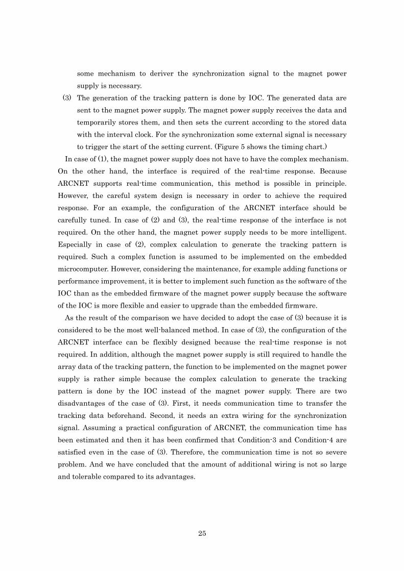
The inverse function of the excitation function is also necessary in order to calculate the K-value conversely from the read back of the setting value or current monitor value.
41
The inverse function is either given in the analytical form or numerically calculated by Newton’s method.
Table 5: excitation functions x: magnetic field (BL), y: current (I), s: polarity of pole changer ps, p0 ~ p11: constant parameters (ps = ±1) Function ID
Number of parameters
Expression Main usage
101 201
8 if y < p6 then x = ps (p0 + p1 y + p2 y2 )
else x = ps (p3 + p4 y + p5 y2 )
obsolete
202 3 x = ps (p0 + p1 y ) BT Steering 203 5 u = ps x
y = p0 + p1 u + p2 u2 + p3 u3
BT Back-leg
301 10 u = ps p8 x if u < p5 then y = p7 (p0 + p1 u + p2 u2 ) else if u < p6 then y = p7 (p0 + p1 u + p2 u2 + p3 (u – p5)2 ) else y = p7 (p0 + p1 u + p2 u2 + p3 (u – p5)2 + p4 (u – p6)3 )
BT Bend BT Quad.
501 7 x = ps (p0 + p1 y + p2 y2 + p3 y3 + p4 y4 + p5 y5 ) unipolar 502 12 if y ≧ 0 then
x = (p0 + p1 y + p2 y2 + p3 y3 + p4 y4 + p5 y5 ) else v = – y x = – (p6 + p7 v + p8 v2 + p9 v3 + p10 v4 + p11 v5 )
bipolar
503 12 if s ≧ 0 then x = (p0 + p1 y + p2 y2 + p3 y3 + p4 y4 + p5 y5 ) else v = – y x = – (p6 + p7 v + p8 v2 + p9 v3 + p10 v4 + p11 v5 )
w/ pole changer
504 3 x = ps (p0 + p1 y ) Back-leg 505 2 y = p0 + p1 x QCS Solenoid 510 0 y = x special case 601 5 x = p0 + p1 y + p2 y2 + p3 y3 + p4 y4 PF-AR 602 10 x = p0 + p1 y + p2 y2 + p3 y3 + p4 y4
y = p5 + p6 x + p7 x2 + p8 x3 + p9 x4
obsolete
603 2 y = p5 + p6 x PF-AR Sx
42

Table 5 shows the list of the excitation functions actually used in KEKB and PF-AR.
Their function form is either a polynomial function or the function whose inverse function is polynomial. In some case, the domain is divided into several sections and a polynomial function is defined for each section. 4-3-3. Virtual parameter and QCS virtual magnet power supplies
Usually the control-K-value, which is the control parameter, has the one to one correspondence to the magnet power supply. In some special case, one control-K-value is corresponding to the multiple magnet power supplies. For such case, even when a single control-K-value is changed, multiple magnet power supplies have to be controlled automatically and simultaneously. More complicated control logics are required to implement such feature. Such a control-K-value is called “virtual parameter” because it has no direct correspondence to a hardware device. The virtual parameter is designed to be similar to the real parameter. Therefore, the similar records are also defined in order to share the API of the ordinary magnet power supply as much as possible. Using such records, user can feel as if the magnet power supply that is corresponding to the virtual parameter exists virtually.
QCS is the superconducting final focus magnet located at each side of the interaction point. The QCS of each side consists of the main quadruple coil, correction coils (horizontal and vertical dipoles and skew quadrupole) and solenoid coil. Each coil is connected to the independent magnet power supply. Although each coil except solenoid is roughly corresponding to the magnetic field component of K1, K0, SK0 and SK1, respectively, these components are mixed each other more or less. Therefore, in order to control the magnetic field precisely, all of the coils have to be treated simultaneously. For this purpose, using 4×4 translation matrix, 4 components of K1, K0, SK0 and SK1 should be mapped to the currents of the 4 coils. The elements of the translation matrix should be determined based on the data of the magnetic field measurement.
In addition, because of the special connection of the main quadruple coils to the magnet power supplies, another type of parameter coupling has to be considered. Two main quadruple coils of both sides are driven by the two magnet power supplies. One is a large power supply named QCS-MAIN and the other is a small power supply named QCS-AUX. QCS-MAIN is connected to the both main coils in series, while QCS-AUX is connected only to the right main coil. Such a special connection causes parameter mixing between both sides of QCS. Including this mixing, 8×8 translation matrix has
43

been introduced and 8 parameters of the both sides of QCS are translated simultaneously.
Thus, the virtual magnet power supplies have been designed for 4 magnetic components and for both sides. Both beams of LER and HER go through QCS. Because of the difference of the beam momentums, the same magnetic field makes the difference of the K-values between LER and HER. Therefore, two sets of virtual magnet power supplies have been implemented separately for LER and HER. Totally 16 virtual magnet power supplies of QCS have been introduced. Setting control-K-values to these virtual magnet power supplies can be done only by the synchronous setting. 4-4. Standardization
Because the magnet with iron core has the hysteresis of the magnetic field, it does not always produce the same magnetic field when the same current is supplied. In order to set the magnetic field with good reproducibility, it is necessary to set current according to the standard procedure, which is defined taking in consideration of the hysteresis loop of the magnet. For the magnet power supply control system in KEKB/PF-AR, 3 procedures have been introduced. They are called “sequence setting”, “standardize setting” and “simple standardize setting”. In addition, the procedure without consideration of the hysteresis loop has been also defined. It is called “direct setting”. Figure 14 and Figure 15 shows the typical behavior of these procedures. 4-4-1. Direct setting
The direct setting is the procedure in which the current is changed toward the target value along the shortest path. Because no consideration of the hysteresis loop is taken, the reproducibility of the magnetic field is bad. This procedure is used mainly for the small amount of the changing current. When the quick setting has the priority than the reproducibility, this procedure is chosen. For the operation of the storage ring with the stored beam being kept, only direct setting can be chosen.
44

Current
time Direct setting
Sequence setting
max
Figure 14: time chart of the direct setting and the sequence setting
4-4-2. Sequence setting
The sequence setting is the procedure in which the current is changed along the standard hysteresis loop. For the magnets of the storage rings, the standard process is defined that setting is done by increasing the current toward the target value. Therefore, when the target value is higher than the current setting point, the current is directly increased to the target value. On the other hand, when the target value is lower than the current setting point, following sequence is processed. First the current is raised to the flat top and then held a certain time. After that, the current is decreased down to the flat bottom and then held a certain time. And then the current is increased to the target value finally.
For the magnets of the BT lines, in contrast to the storage rings, the standard process is defined that setting is done by decreasing the current toward the target value. That means the current setting path goes in opposite direction compared to the storage rings.
As long as the setting is always done by the sequence setting, current changing path always keeps on the same hysteresis loop and then the reproducibility of the magnetic field is always kept. For example, the sequence setting has been frequently used at the switching configuration of the electron BT line. The settings of some magnet power supplies are frequently switched between KEKB injection and PF-AR injection. The switching is usually done by the sequence setting. 4-4-3. Standardize setting
When the direct setting is used repeatedly, the setting point of the magnetic field gradually moves out of the standard hysteresis loop. It makes the reproducibility of the magnetic field worse. In order to eliminate this effect and reset the setting point on the standard loop, the standardization has been introduced. The standardization is the
45

procedure that the current goes up and down between flat bottom and flat top several times and then finally goes down to zero current. The standardize setting is the automatic sequence that after the standardization the sequence setting follows. In other word, the standardization is a special case of the standardize setting, whose target value is zero current.
The standardize setting is the most time consuming procedure. The standardize setting is usually applied on all magnet power supplies when the operation starts or the optics changes significantly. In addition, after the unexpected change such as the cutoff by the interlock occurs, the standardize setting is also used in the recovery process.
The flat top current is usually defined equal to the maximum rated output current of the magnet power supply. The flat bottom current is usually defined equal to zero current. In case of the bipolar power supply, the flat bottom current is defined equal to either zero current or maximum negative current. The number of times of the going up and down of the current is defined typically 3 to 5, depending on the type of magnet. In any case, such a definition has been determined identical to the procedure which has been applied at the magnetic field measurements of the magnets. Because the excitation function has been determined based on the data of the magnetic field measurements, the standardize setting is the standard method to reproduce the measured magnetic field. Current
time
max
Figure 15: time chart of the standardization
4-4-4. Simple standardize setting
Because the standardize setting is time consuming, simpler procedure is also introduced. The simple standardize setting is light-weight version of the standardize setting. It is almost same as the standardize setting except the number of times of the going up and down of the current is reduced to 1. This procedure is less reproducible but faster than the standardize setting.
46

4-5. Asynchronous setting and Synchronous setting
In KEKB/PF-AR magnet power supply control system, two methods of the setting current have been introduced. One is asynchronous setting and the other is synchronous setting. Using the synchronous setting, multiple magnet power supplies can change their current synchronously each others. When the synchronization is not necessary, the asynchronous setting is also available. 4-5-1. Asynchronous setting
In the asynchronous setting, each magnet power supply can perform the setting operation independently. For the asynchronous setting, any of the 4 procedures (direct setting, sequence setting, standardize setting and simple standardize setting) can be chosen. Specifically, the records shown in the table 6 are used for the asynchronous setting. The setting process starts by writing the control-K-value to one of these records. The setting value can be specified not only by the control-K-value but also by the current. The setting by the current is used for the test of the magnet power supply itself.
Table 6: record list for asynchronous setting Setting procedure Set by the control-K-value Set by the current
Direct setting header:name:KDIR header:name:IDIR
Sequence setting header:name:KSEQ header:name:ISEQ
Simple standardize setting header:name:KSST header:name:ISST
Standardize setting header:name:KSTD header:name:ISTD
4-5-2. Synchronous setting
For the synchronous setting, the setting value can be specified only by the control-K-value. The setting by the current is not supported. In addition for the synchronous setting, only direct setting is available. The procedures with the consideration of the hysteresis loop (i.e. sequence setting, standardize setting and simple standardize setting) can not be chosen for the synchronous setting. 4-5-2-1. Synchronous setting server
47

Comparing to the asynchronous setting, the sequence of the synchronous setting is more complicated because the cooperative behavior among the multiple magnet power supplies is required. Therefore, the synchronous setting server has been introduced. It is the server program which drives the sequence of the synchronous setting. Figure 16 shows the schematic view of the synchronous setting server and the related records. In order to request the synchronous setting, the higher-level application program put the request to the records shown in Table 7. After putting the list of the magnet power supplies and the list of the control-K-values to be set, the sequence of the synchronous setting starts by putting a value to the set time record. The synchronous setting server communicates with the records of the specified magnet power supplies (PS-records) using Channel Access and acts as a mediator. The sequence of the synchronous setting consists of the following steps.
(1) The synchronous setting server accepts the request from the application program. The parameters passed are an array of ID of the magnet power supplies, an array of the control-K-values to be set and the time spent in changing currents (the set time).
(2) The synchronous server sends the control-K-value to each PS-record. (3) Each PS-record translates the given control-K-value into the current, and then
estimates the minimum time required for the changing current and sends it back to the synchronous setting server.
(4) The synchronous setting server checks whether all of the minimum times sent back from the PS-records are shorter than or equal to the set time. When the application program does not specify the set time, the maximum value among the minimum values sent back from the PS-records is adopted as the set time.
(5) The synchronous setting server informs the PS-records of the finally fixed set time.
(6) Each PS-record calculates the tracking data from the current value, the target value and the set time. And then it transmits the tracking data to the PSICM.
(7) Each PS-record monitors the status of the PSICM. When the PSICM becomes ready to start tracking, the PS-record gives a notice to the synchronous setting server that it is ready.
(8) The synchronous setting server waits until all PS-records become ready. And then it generates the synchronous start signal, by which the PSICM starts tracking.
(9) The synchronous setting server checks whether all PS-records start tracking. The synchronous setting server has been written in Python language and runs on the
48

central control server. In the original plan, the synchronous setting server was written in C language and ran on the IOC. In order to verify the logics of it, the synchronous setting server has been developed in Python language as a test version and was used for the trial operation early in the commissioning. As the result of the trial, it has been found that the synchronous setting server even in Python language has enough response speed. Therefore, the test version in Python language has become the final version. There have been many advantages of using the high-level language like Python. It makes many things easy such as the coding, debugging, upgrading, and so on. It greatly improves the efficiency of the maintenance.
PS1 PS2 PS3
PS-records
Synchronous setting server
Application Program
UNIX based servers(OPI layer)
Power supply List
Control-K-value List
API records
Trigger record
IOC in the central control room IOC in the local control room
Synchronousstart signal
Set time IOCTMCCC IOC for timing system
ARCNET
Figure 16: synchronous setting server and related records
Table 7: record list to request synchronous setting For KEKB LER For KEKB HER For PF-AR
Power supply list MGLPSS:LER:PSID MGHPSS:HER:PSID MGAPSS:AR:PSID
Control-K-value list MGLPSS:LER:K MGHPSS:HER:K MGAPSS:AR:K
Set time MGLPSS:LER:T MGHPSS:HER:T MGAPSS:AR:T
49

4-5-2-2. Synchronous pole change server
Some of the unipolar magnet power supplies have the pole changer which can be remotely controlled. The magnet power supply with the pole changer can be considered as the pseudo bipolar magnet power supply. Therefore, it has been requested that some mechanism which automatically changes the polarity of the magnet power supplies according to the given target setting values should be introduced into the control software. Because this request was not included in the original specification, the mechanism has been implemented as the additional server program. For simplicity, the automatic pole change has been supported only in the synchronous setting. Thus, the synchronous pole change server, which automatically executes the adequate sequence of the pole change with the synchronous setting, has been developed and introduced. For the asynchronous setting, user must explicitly command the pole change if necessary because no automatic pole change is available.
Figure 17 shows the schematic view of the synchronous pole change server and the related records. The application programming interface of the synchronous pole change server has the similar specification to the synchronous setting server. In order to request the synchronous setting with the automatic pole change, the higher-level application program put the request to the records shown in Table 8. After putting the list of the magnet power supplies and the list of the control-K-values to be set, the sequence of the synchronous setting with the automatic pole change starts by putting a value to the set time record. The synchronous pole change server communicates with the PS-records using Channel Access and sends commands of pole change to the PS-records and requests the synchronous settings to the synchronous setting server. The sequence of the synchronous setting with the automatic pole change consists of the following steps.
(1) The synchronous pole change server accepts the request from the application program. The parameters passed are an array of ID of the magnet power supplies, an array of the control-K-values to be set and the time spent in changing currents (the set time).
(2) The synchronous pole change server translates the given control-K-value of each magnet power supply into the current, and then determines whether the pole change is required for the magnet power supply with the pole changer.
(3) If the pole change is required, the synchronous setting is divided into two sections of synchronous setting which are carried out before and after the pole change, respectively. The division point is determined to be the time at which
50

the current of the magnet power supply become zero during changing current. (4) If more than two magnet power supplies are required of the pole change, the
division points are determined for all of them. When a number of the required magnet power supplies is N, the synchronous setting is divided into N+1 sections.
(5) The synchronous pole change server requests the synchronous setting server to execute the synchronous setting of the first section. And then the synchronous pole change server checks whether the synchronous setting has normally started or not by the return code of the synchronous setting server.
(6) The synchronous pole change server waits completion of the changing current of the magnet power supply of the pole change and waits until its current becomes zero, and then starts changing its polarity. In order to execute pole change, the synchronous pole change server sequentially sends commands of power off, pole change and power on to the magnet power supply.
(7) If more than two magnet power supplies are required of the pole change, (5) and (6) are repeated similarly.
(8) After all of the pole change has completed, the synchronous pole change server requests the synchronous setting server to execute the synchronous setting of the last section. And then the synchronous pole change server checks whether the synchronous setting has normally started or not by the return code of the synchronous setting server.
The synchronous pole change server automatically determines the necessity of the pole change by the given target setting value. If no pole changes are required, the target setting values are just passed directly to the synchronous setting server. In such case, the synchronous pole change server behaves as exactly equal to the synchronous setting server. Thus, the synchronous pole change server can be considered as the enhanced version of the synchronous setting server.
The synchronous pole change server has been also written in Python language and runs on the central control server.
51
PS1 PS2 PS3
PS-records
Synchronous setting server
Application Program
UNIX based servers (OPI layer)
API records
Trigger record
IOC in the central control room IOC in the local control room
Synchronousstart signal
Power supply List Control-K-value List
Set time
IOCTMCCC IOC for timing system
ARCNET
Synchronous pole change server
Power supply List Control-K-value List
Set time
pole change
Figure 17: synchronous pole change server and related records
Table 8: record list to request synchronous setting with the automatic pole change For KEKB LER For KEKB HER
Power supply list MGLPSSS:LER:PSID MGHPSSS:HER:PSID
Control-K-value list MGLPSSS:LER:K MGHPSSS:HER:K
Set time MGLPSSS:LER:T MGHPSSS:HER:T
4-6. Exclusion control for the magnet with auxiliary coils
Some of the magnets have the auxiliary coils which are connected to the independent magnet power supplies. The auxiliary coils are used for the various purposes. Especially the auxiliary coil of the main bending magnet is frequently used for the orbit correction as an alternative to the horizontal steering magnet.
Here, for the magnet which has the auxiliary coil other than the main coil, the magnet power supply connected to the main coil is called “main power supply” and the magnet power supply connected to the auxiliary coil is called “auxiliary power supply” for short. The standardization for such magnet is usually performed only by the main
52

power supply with the auxiliary power supply fixed to no current. Therefore, the magnetic field at the flat top is defined by the maximum rated current of the main power supply. Because main and auxiliary power supplies can be operated independently, undesirable operation is possible. If the main power supply is operated at the maximum current or close to the maximum current and simultaneously the auxiliary power supply outputs current, the magnetic field may exceed the expected operation range. In order to avoid such an undesirable situation, attention should be always paid to the setting values and the setting procedures of the both power supplies. However, it seems imperfect and inefficient to depend only on human attention. Therefore, the logics to avoid undesirable situation automatically has been introduced. The logics prohibit a certain operation during a certain state. The specific logics are shown in the followings. Here, x is the constant percentage which is defined for each set of the main power supply and auxiliary power supply.
(1) When the main power supply satisfies one of the Condition-A, the auxiliary power
supply is prohibited from any of the Operation-B Condition-A:
(i) The main power supply is busy. (ii) The main power supply is local mode. (iii) The main power supply is not accessible. (iv) The main power supply is power on and the absolute value of the setting
current is grater than or equal to the x % of the maximum rated current. Operation-B:
(i) Changing the setting current (ii) Power on (because non-zero offset current may be output just after the
power on.) (2) When the auxiliary power supply satisfies one of the Condition-B, the main power
supply is prohibited from any of the Operation-A Condition-B:
(i) The auxiliary power supply is busy. (ii) The auxiliary power supply is local mode. (iii) The auxiliary power supply is not accessible. (iv) The auxiliary power supply is power on and the setting current is non-zero.
Operation-A: (i) Sequence setting (ii) Standardize setting
53

(iii) Simple standardize setting (iv) Changing the setting current that the absolute value of the target current is
greater than or equal to the x % of the maximum rated current. These exclusion controls have been implemented on the IOC by the IOC database.
The records of the main power supply and the records of the auxiliary power supplies are designed to be linked each others to exchange information.
These exclusion controls can be considered as the interlock system implemented by software. Especially for the bending magnets of the injection BT lines, another interlock system has been introduced by hardware using meter relays as the extra protection system against the failure of the software exclusion controls. This interlock system forcibly cut off the current of the auxiliary power supply when the current of the main power supply exceeds the threshold. 4-7. Implementation of the software on the IOC
Most of the software shown in this chapter has been implemented on the IOC except the synchronous setting server and the synchronous pole change server. It is the basic style in EPICS that the software of the control system is constructed by defining records on IOC. The record is the building unit of the control system. In EPICS, many kinds of ready-made general purpose records are available. Initially the magnet power supply control system in KEKB was designed using such general purpose records and partially implemented for the magnet power supplies in the electron BT line. However, during implementing the required full functions, the IOC database became too complicated to maintain. The complication came from the fact that the ready-made records are general purpose but have only simple functions. Therefore, it needs to combine many records to implement the complex function. In order to reduce the complexity, we have decided that not only the general purpose records are used but also some special purpose records dedicated to the magnet power supply should be developed and the most of the control logics should be implemented inside the dedicated records. Thus, the original design of the software has been largely changed based on the experience of the initial development of the electron BT line.
In EPICS, user can use not only general purpose record types but also can define new record types. The behavior of the record is defined by coding some program, which is called “record support”. The record support is usually written in C language. Therefore, developing the dedicated records means that the control logics are written in C
54

language. The following 2 records have been newly developed, which are dedicated for the magnet power supply. ・psstsin record ・hugesub record
The psstsin record receives an ARCNET packet sent from the PSICM. It has the array which holds the data of the status information sent from the PSICM. Its record support has been developed based on waveform record, which is one of the EPICS standard records and can handle array data. Comparing to the waveform record, the psstsin record has the additional fields to access each element of the array data. Each of the additional fields has its own name which is corresponding to each status of the PSICM. The psstsin record itself just holds the array data and does not have any special logics dedicated to the magnet power supply. The main role of the psstsin record is providing the status information of the magnet power supply to the hugesub record.
The hugesub record has the subroutine in which the control logics of the magnet power supply are written in C language. The most of the functions described in this chapter have been implemented in this subroutine. The record support of the hugesub record has been developed based on sub record, which is one of the EPICS standard records and can call a user-written subroutine. The name “hugesub” comes after sub record and the fact that number of fields are largely extended. Comparing to the sub record, the hugesub record also has the special purpose fields whose name is specific to the magnet power supply. Therefore, the hugesub record is the dedicated record to the magnet power supply.
The control logics of each magnet power supply has been implemented as a group of about 50 records, which consists of a hugesub record as the core, psstsin record and some EPICS standard records, and so on. The EPICS standard records are introduced as the interface record which is designed to be accessed from the higher-level application programs using Channel Access or as the auxiliary record of the control logics. Figure 18 shows the relation among these records.
55

Status input recordARCNET packetoutput record
The record to receive requested control-K-value PS-record
UNIX based servers
IOC
Application program
A set of records for a single magnet power supply
From ARCNET To ARCNET
header:name:KDIR
CA
hugesub record
psstsin record
Figure18: control flow inside the IOC
56

5. User application programs for the operation
In this chapter, in order to show how the magnet power supply control system has been used in the actual operation of the accelerators, several examples of the higher-level application programs written by users are introduced. As described before, these programs are considered to be user application programs from the view of the control system. Initially the “users” were assumed to be the members of the commissioning group, but not only these people but also other various people have been participated in the development of the various application programs. The application programming interface (API) of the magnet power supply control system has been implemented as the set of EPICS records on the IOC. These records have been designed to be uniformly treated regardless of the type of the magnet and the magnet power supply. Therefore, in the development of the user application programs, the magnet power supply can be treated as the abstracted device without considering the detailed differences of the hardware. It makes user programming easier. During a decade of the commissioning of the KEKB accelerators, many application programs have been developed and have contributed to the tuning up and improvement of the accelerators. In the following sections, the typical application programs which are relatively large scale and have been used for a long time are shown. 5-1. Operation panel for the storage rings
The operation panel for the storage rings is one of the user interface program for the general operations of the magnet power supplies. This panel handles the magnet power supplies in LER and HER. The operation can be done by GUI (Graphical User Interface). This program has been developed by the magnet group. The actual author is Mr. Yoshii. The program has been written in Python. For its GUI, tcl/tk is adopted and Tkinter, which is the Python interface of tcl/tk, is used.
This program has various functions and consists of the aggregation of the GUI panels. Figure 19a shows the appearance of the top level panel. User can choose the various panels to launch as necessary at the top level panel. The major functions of the program are followings. ・Individual operation panels (shown in Figure 19b) ・Collective operation panels ・Standardization panel for the whole rings ・Standardization panel for the individual magnet power supply
57

Figure 19a: top level menu of the operation panel for the storage rings
Figure 19b: individual operation panel popped up from the operation panel
58

The main users of this program are the operators and the members of the magnet
group. This program has been used not only in the operation of the accelerators but also used for the maintenance of the magnets and the magnet power supplies. 5-2. Operation panel for the injection BT lines
The operation panel for the injection BT lines is one of the user interface program for the general operations of the magnet power supplies. This panel handles the magnet power supplies in the positron and electron injection BT lines of KEKB. It also handles the PF-AR injection BT line, whose upper stream part is shared with the KEKB electron BT line. The operation can be done by GUI (Graphical User Interface). This program has been developed by the author according to the specifications given by the BT group. The program has been written in Python. For its GUI, tcl/tk is adopted and Tkinter, which is the Python interface of tcl/tk, is used.
Figure 20 shows the appearance of this panel. Comparing to the operation panel for the storage rings shown in the previous section, this program has not many GUI panels, but has been designed that most of the functions can be operated in the main panel. The various functions can be selected by the pull-down menu of the main panel. The collective operation of the multiple magnet power supplies is also possible in the main panel by selecting the operation after selecting the magnet power supplies. Thus, its design framework is different from the operation panel for the storage rings. However, for the individual operation panel, user can also choose another style of panel which is same as the panel for the storage rings, i.e. the unified operability has been provided. The major functions of the program are followings. ・Individual operation panels ・Selection functions for the collective operation ・Collective operations ・Save/Load operation of the setting value ・Guidance of the sequence of changing momentum
Historically, each of these functions was implemented as an individual program. Later they are gradually incorporated into this program. The main users of this program are the operators and the members of the BT group. This program has been used not only in the operation of the accelerators but also used for the maintenance of the magnets and the magnet power supplies.
59

Figure 20: main panel of the operation panel for the electron BT line (left) and individual operation panel popped up from the main panel (right) 5-3. Injection mode switching panel for the BT line
The KEKB electron injection BT line and the PF-AR injection BT line share the upper stream part and the simultaneous injections into the both rings are impossible. Therefore, whenever the injection switch is required, the setting values of the shared magnet power supplies have to be switched between two injection modes. In the regular operation, PF-AR needs injection twice a day. The switching operation is a daily routine work and has been required to introduce some automation for the laborsaving. For this
60

purpose, the program dedicated to the switching operation has been developed. This program switches between KEKB injection mode and PF-AR injection mode. In addition Linac mode, which is the operation mode without injection into any rings, can be also selected. The operation can be done by GUI (Graphical User Interface). This program has been developed by the author according to the specifications given by the BT group. The program has been written in Python. For its GUI, tcl/tk is adopted and Tkinter, which is the Python interface of tcl/tk, is used.
In this program operator can select the switching operation to be executed at the top level panel, and then after checking the current setting, the sequence of the required actions to the magnet power supplies are automatically generated. The generated sequence is graphically shown as a diagram on the panel. Figure 21 shows the top level panel and the diagram panel. Automatic executing of the sequence starts by pressing “Start” button. During the execution, status of each step of the sequence is shown on the diagram on the panel. Thus, the status of progress can be understood at a glance. When the current is cut off by some interlocks of the magnet or the magnet power supply for example, the operator can intervene manually in the sequence and can take an appropriate action according to the fault state shown on the diagram.
Figure 21: injection mode switching panel for the BT lines; top menu (left) and sequence diagram (right) 5-4. Optics panel for the storage rings
The optics panel is the program which set the optics for LER and HER. The operation can be done by GUI (Graphical User Interface). Figure 22 shows an example of the
61
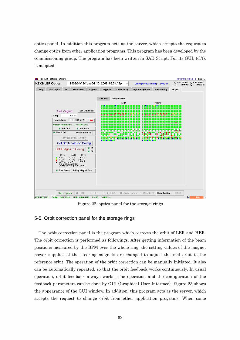
optics panel. In addition this program acts as the server, which accepts the request to change optics from other application programs. This program has been developed by the commissioning group. The program has been written in SAD Script. For its GUI, tcl/tk is adopted.
Figure 22: optics panel for the storage rings
5-5. Orbit correction panel for the storage rings
The orbit correction panel is the program which corrects the orbit of LER and HER. The orbit correction is performed as followings. After getting information of the beam positions measured by the BPM over the whole ring, the setting values of the magnet power supplies of the steering magnets are changed to adjust the real orbit to the reference orbit. The operation of the orbit correction can be manually initiated. It also can be automatically repeated, so that the orbit feedback works continuously. In usual operation, orbit feedback always works. The operation and the configuration of the feedback parameters can be done by GUI (Graphical User Interface). Figure 23 shows the appearance of the GUI window. In addition, this program acts as the server, which accepts the request to change orbit from other application programs. When some
62

program request bump orbit to be set, this program not only directly change the steering magnets but also update the reference orbit including the bump orbit. This program has been developed by the commissioning group. The program has been written in SAD Script. For its GUI, tcl/tk is adopted.
Figure 23: orbit correction panel for the storage rings
63

6. PF-AR magnet power supply control system
Originally the magnet power supply control system using ARCNET and PSICM has been designed only for KEKB accelerators. Later it has been able to be applied also to the upgrade of the PF-AR. In this chapter the history of the application and the additional features specific to the PF-AR are described. Table 9 shows the numbers of magnets and magnet power supplies in the PF-AR.
Table 9: numbers of magnet power supplies in PF-AR Numbers of magnets are also shown in parentheses.
PF-AR
Bend 1 (56) Steering 89 (89) Quadrupole 28 (86) Sectupole 4 (38) Octupole 4 (4) Back-leg 56
Total 182 (273)
6-1. Upgrade of PF-AR
After starting operation of KEKB, in 2001, PF-AR accelerator has been upgraded. At that time the magnet power supply control system has been completely updated to be the nearly same of KEKB. PF-AR was originally Accumulator Ring (AR), which was the pre-accelerator of the TRISTAN Main Ring. After the shutdown of TRISTAN, AR has been modified and diverted to be the light source machine. Therefore, most of the components of the accelerator had been inherited from TRISTAN. The control system had been also inherited from TRISTAN. Because of such history, KEKB and PF-AR have many common features. In addition KEKB and PF-AR share the following items.
• They share the upper stream part of the electron injection BT line. • They share the network of the control system. • They share the central control room. • They share some of power supply building and some of local control rooms. • Many stuffs in KEKB also participate in the operation and the maintenance of
PF-AR. At the upgrade of PF-AR, the KEKB magnet power supply control system has been
64

finished development and started operation. Because of these circumstances, it has been considered relatively easy to apply the KEKB magnet power supply control system to the PF-AR, so that the efficient development has been expected.
On the other hand, PF-AR has some different feature from KEKB. For the magnet power supply control system, the following points should be considered.
(1) In PF-AR, the beam is injected at 2.5GeV (later 3GeV), and then acceleration to 6.5GeV is required.
(2) In PF-AR, most of the existing magnet power supplies have been continued to use except small ones while in KEKB most of the magnet power supplies have been newly produced.
(3) For the downstream part of the injection BT line of PF-AR (the dedicated line to PF-AR after the branching point from the KEKB line), the magnet power supplies has been left untouched by the financial reason.
The solutions of these problems are discussed below. 6-2. Treatment of the existing magnet power supplies of PF-AR
As described in (2) in the previous section, it has been necessary to consider the treatment of the existing magnet power supplies in PF-AR when the same magnet power supply control system in KEKB has been applied. In PF-AR, the existing magnet power supply itself has not been modified but the signal converter has been installed between the IOC and the magnet power supply while in KEKB the existing magnet power supply has been modified to accept the PSICM. The signal converter has the PSICM plugged-in to communicate with the IOC through ARCNET. And it has the connection with the same signal lines as the CAMAC system to the magnet power supply. Thus, the difference between the old and new interfaces has been eliminated by introducing additional hardware, so that both the existing magnet power supplies and the new magnet power supplies can be treated equally in the unified manner from the view of the control system. 6-3. Tracking of the acceleration of PF-AR
For the acceleration of PF-AR, the tracking of the magnet power supplies has been introduced by applying the feature of the synchronous setting in the KEKB magnet power supply control system. Comparing to KEKB, the following points should be considered for the tracking of the acceleration.
65

• All of the magnet power supplies in the ring are involved. • The span of change of the magnetic field (the current of the power supply) is
large. • The tracking parameters are not only the control-K-values but also the beam
momentum. • The RF voltages are also required to be changed synchronously. • The tracking pattern should be able to be flexibly configured by users • The same tracking pattern should be able to be used every operation.
In addition to the acceleration, other routine operations such as deceleration, and so on have been also supported by the same framework of the synchronous setting. The tracking of the acceleration and these operations are called “regular tracking”. For these operations except the acceleration, although the synchronization among the magnet power supplies is not always required because sometimes no beams are stored during the operations, the synchronous setting is always used for simplicity. Thus, the control software has been simplified by using the single framework in the unified manner. It gives a good perspective also to the user application programs.
For the regular tracking, the PSICM and the ARCNET system installed are exactly the same of KEKB without any modifications. As the span of change of the current is relatively large, up to 4000 steps are required to configure the tracking pattern for the regular tracking. However, the PSICM has enough memory to hold such large steps even in the original specification, so that no modifications have been necessary.
On the other hand, the software on the IOC and the synchronous setting server have been modified by adding some extensions for the regular tracking. Each magnet power supply has the additional array records which hold the tracking data. These tracking data are configured by writing directly to the records by the user application programs. The data of the record consists of the sequence of the control-K-values. Additional records which hold the tracking data of the beam momentum are also introduced. The record is installed for each kind of operation such as acceleration, deceleration, and so on. Up to 12 kinds of operations can be configured. And they are identified by a number (tracking number). The regular tracking can be operated only in the synchronous setting. The synchronous setting server accepts the request of the regular tracking with the tracking number. More specifically, it is initiated by putting the special value corresponding to the tracking number to the set time record instead of the set time.
In order to synchronize the RF voltage, the PSICM is also used for the interface to the RF voltage control. The RF voltage is set by using the setting DAC function of the PSICM. Thus, setting RF voltage can be treated as setting to a magnet power supply. As
66

PF-AR has two RF cavities at the east and west stations, two sets of the records of them have been introduced. For each RF voltage, the array records which hold the tracking data are also available and any tracking pattern can be configured. 6-4. Control system of the injection BT line of PF-AR
For the downstream part of the injection BT line of PF-AR (the dedicated line to PF-AR after the branching point from the KEKB line), the CAMAC system as the interface to the magnet power supplies has been left untouched. The CAMAC crate controller has been connected to the IOC through the serial highway. On the other hand, as the upper stream part of the injection BT line of PF-AR is shared with the electron injection BT line of KEKB, the PSICM and ARCNET system has been introduced there. In order to operate the downstream part in the unified manner similar to the upper stream part, additional software on IOC has been introduced to eliminate the differences of the hardware interfaces. Specifically, following emulations have been introduced, and then the control software for KEKB has been applied also on the downstream part as much as possible with the emulations.
(1) For the commands of power on, power off and reset interlocks to the magnet power supply, the case is analyzed in the subroutine in the PS-record, and then if CAMAC is used, the output record assigned to the CAMAC is processed.
(2) For setting current, generating the pattern data is common to the case of PSICM. After that, only the last value of the pattern is set in case of CAMAC.
(3) The input data from the CAMAC module such as the status information are converted into the format which emulates the status packet from the PSICM.
Thus, introducing the emulations in the low level software close to the hardware in order to eliminate the difference of the interfaces, user can treat the magnet power supply in the unified manner regardless of the upper or downstream parts of the BT line, and then most of the programs for the KEKB BT lines can be used also for the PF-AR BT line with little modification.
67

7. Discussion
So far, the magnet power supply control system has been discussed according to the KEKB/PF-AR case. In this chapter, discussing its methodology of the system design, more general analysis is shown. Several guidelines to design control system can be concluded from this study. Such guidelines are described in the following sections. 7-1. Simplification
Upon designing the KEKB/PF-AR magnet power supply control system, the most severe problem was an amount of wirings. Comparing to the previous TRISTAN control system using CAMAC, the amount of the signal cables has been greatly reduced by introducing the new interface based on the serial communication. In addition, if the CAMAC system was adopted, many components such as serial highways, crate controllers, crates, various types of I/O modules, terminal blocks, and so on were required between the IOC and the magnet power supply. Introducing PSICM, the IOC and the magnet power supply can be directly connected with a serial cable, so that the system has been greatly simplified (although there are some exceptions of introducing the hub). Upon designing the control system, it is possible to simplify the system by eliminating the unnecessary parts which is not essential. The simplification reduces the load of the construction and also the load of the maintenance, so that the reliability is promoted. 7-2. Unification
In KEKB/PF-AR, there are bending magnets, quadrupole magnets, sextupole magnets and steering magnets, and so on. There are various magnet power supplies from small one to large one. In generally speaking, the design scheme to develop each system optimized for each type of devices is possible. However, in KEKB/PF-AR, we have chosen to develop the unified system over these differences. Comparing to the heterogeneous system, the homogeneous system is efficient for the development and the maintenance. The unified system has the advantage that the limited resources for the development and the maintenance can be concentrated on the single point, so that the reliability is also promoted. Although the unification is considered to be one of the specific methods of the simplification, it should be still emphasized that the unification is the key point of the system design.
68

The question may arise. What kinds of devices should be unified? It is important to decide the range of the unification. It is not appropriate to unify everything. The magnet power supply and the vacuum pump should not be unified, because they are too different in hardware and also in operation. If you try to unify the devices with large difference, the system becomes rather complicated. In KEKB/PF-AR, some magnet power supplies are excluded from the unified system. They are the pulsed power supplies and the power supplies for the fast orbit feedback. The pulsed power supplies are used for the injection septum magnets, the injection kicker magnets and the abort kicker magnets, and so on. They are excluded from the unification mainly because of the difference in the hardware. The power supplies for the fast orbit feedback at the IP and at the Crab Cavity are excluded from the unification mainly because of the difference in the operation. In addition, some of the power supplies for the solenoids are also excluded from the unification for another reason. Because these power supplies are the reuse of the old power supplies, the modification to introduce the PSICM was required if they were included in the unification. The solenoids have been installed on LER in order to sweep out the electron cloud. For this purpose, they are driven with the constant current and any other complex operations are not required. Of course synchronous setting is never required for their power supplies. So we have concluded that the unification of the solenoid power supplies is not beneficial compared to the required work to introduce the PSICM.
Even for the very different devices, unified treatment is possible in some case. In PF-AR, RF voltage can be treated as the current of the magnet power supply. It has the same interface as the magnet power supply. It is treated as one of the magnet power supplies in the software. Introducing such unification, the synchronous ramping of the RF voltage in the acceleration can be easily implemented in simple manner. 7-3. Prerequisite and limit of application of the methodology
Can the methodology applied in KEKB/PF-AR magnet power supply control system be also applied to any other accelerators? Unfortunately, it can be applied only under certain conditions. The unconditionally universal method like a magic does not exist. What circumstances influence the system design of the KEKB magnet power supply control system? Following 2 situations have determined the characteristics of the system design.
(1) The large numbers of the magnet power supplies have been introduced. (2) Most of them have been newly designed and developed.
69

Because of the large numbers, the amount of wirings has become problem. On the other hand, the large number is advantageous for the mass production of the PSICM. If the number was of order tens, the CAMAC system could be continued. If the number was a couple of hundreds, the wirings of the CAMAC system were uncomfortable but still tolerable. Because the number is a couple of thousands, the serial communication system has been chosen even though the development and the mass production of the PSICM have been required.
More than anything else, it has determined the design direction of the control system that almost all magnet power supplies have been newly designed. The PSICM has been developed in parallel with the development of the magnet power supply itself in collaboration with the magnet group. We have had the full flexibility to choose interface because of the new development. If most of the magnet power supplies were existing ones, their interface could not be chosen other than the existing one. If the magnet power supplies were newly purchased but were ready-made commercial products, the choice of the interface was more or less limited. Especially it would be difficult to unify the interface if each type of the magnet power supply was individually chosen from the ready-made products. 7-4. Balance between hardware and software
The recent progress of the computer technology is remarkable. Computers are introduced everywhere in the control system as the embedded system. The role of the software becomes more and more significant for the control system. The required functions should be implemented in software as much as possible while hardware can be simplified, so that the reliability of the hardware can be promoted. Generally speaking, such a scheme is reasonable as a major trend. However, in some case, sharing some functions with the hardware, the development of the software becomes much easier. The simplification should be considered not only for the hardware but also for the whole system including software.
In KEKB/PF-AR case, the synchronous setting has been designed that the tracking data are sent to the PSICM beforehand and then special hardware (synchronous start signal) triggers the synchronous tacking. If the IOC is designed to put the value directly to the DAC every step of the tracking, the hardware can be simpler but the software on the IOC is required to control the real-time tracking in every millisecond including ARCNET communication. As the tracking control has been shared by the PSICM, the software on the IOC has not been required the real-time response any more. Thus, the
70

development of the software has been much easier. On the other hand, it is desirable that the PSICM takes share of minimal functions as little as possible because the firmware on the PSICM is less flexible than the software on the IOC. Therefore, more intelligent but non-real-time processing such as the calculation of the tracking data has been designed to be done on the IOC. Thus, the appropriate balance of the share of the functions between hardware and software or between the firmware on embedded computer and the software on upper level computer (IOC) is the key point of the system design.
71

8. Summary
In the development of the KEKB magnet power supply control system, the design has started from the interface between the magnet power supply and the IOC. At first, the reuse of the CAMAC system of TRISTAN was one of the candidates. But it was finally excluded from our choices. The problem of the CAMAC system was the parallel wirings between CAMAC modules and the magnet power supplies. It required large amount of wirings for more than 2200 magnet power supplies of KEKB rings. Instead of the CAMAC system, we have considered the system which utilizes serial communication in order to reduce the amount of wirings. In the final design, all signals are exchanged through the single serial line. Although the additional cables have been introduced exceptionally for the current monitor system, which consists of the scanner and DVM to measure the analogue signal directly from the magnet power supplies, totally the wirings have been greatly simplified compared to the TRISTAN control system.
The next step of design was the choice of the serial interface. Assuming some actual operation, required precision and speed have been estimated. In the assumed operation, the synchronous operation among the multiple magnet power supplies has been required. As the result of the comparison of the 3 methods, the synchronous setting has been designed that the tracking data are calculated in the IOC and sent to the magnet power supply beforehand and then the synchronous start signal triggers the synchronous tacking. In this method the magnet power supply is required to store the array data for the tracking and to set them in sequence with the interval clock. Although it requires some intelligence in the magnet power supply, total system can be simplified and flexible operation is possible. ARCNET has been adopted as the serial interface. It supports relatively long packet and communication speed is enough for our purpose. Because the controller chips on which the communication protocol is implemented are available, it is easy to construct the system. The twisted-pair cable with HYC2485 media driver has been chosen as the media of ARCNET. This configuration allows multi-drop wiring. The synchronous start signal is also delivered by the cable combined with ARCNET. Thus, the simplification of the wirings has been achieved.
For the implementation of the ARCNET interface, the PSICM has been developed. It is the plug-in module in the magnet power supply and has an ARCNET interface and a microcomputer with the control software (firmware). The PSICM has been introduced into all magnet power supplies regardless of the makers. Introduction of the unified module makes the maintenance much easier and efficient. In addition, the VME
72

modules for the ARCNET interface and the ARCNET hubs have been also developed. They are dedicated modules to the magnet power supply control as they distribute the synchronous start signal with the ARCNET.
Finally the control software has been developed. In EPICS, two types of computers are used. One is the IOC, which is the frontend computer directly connected to the hardware devices. The other is the OPI, which is the higher level computer that runs the application programs. In the KEKB magnet power supply control system, the PSICM also has software. Therefore, the control software is distributed over the 3 layers of OPI, IOC and PSICM. They have been designed to work cooperatively to achieve the required functions. In KEKB, the application programs on the OPI are developed basically by the users such as the operation group. Because the software of the PSICM is fixed on the ROM, it is less flexible than IOC. Considering the maintenance of the software, the PSICM has been designed to have only simple minimal functions without high intelligence. Major functions incorporated in the magnet power supply control system are followings.
(1) The translation from the magnetic field to the current for the setting operation should be incorporated into the setting operations.
(2) The regular sequence of the setting current to reduce the hysteresis problem should be supported.
(3) Synchronous setting of the multiple magnet power supplies should be supported.
(4) For PF-AR, the pattern operation of the acceleration or any other pattern should be easily carried out. The pattern should be flexibly configured.
Most of these functions have been implemented in software. To implement them, some EPICS record types dedicated to the magnet power supply control have been newly developed. Most of the control logics have been implemented on these records and written in C language. These record types are common to all magnet power supplies regardless of the types of the magnet power supplies.
In KEKB, unified objects have been consistently used from the hardware such as the ARCNET and the PSICM to the software. They have been designed to be handled in unified manner regardless of the types or makers of the magnets and magnet power supplies, and uniformly introduced without distinction of LER, HER, positron BT line and electron BT line. Such unification makes the maintenance of both hardware and software easy. In addition, at the upgrade of PF-AR, the same system as KEKB has been able to be introduced. In PF-AR, the exactly same PSICM as KEKB is used. Most of the IOC database for PF-AR is common to KEKB. The functions for the regular
73

tracking for the acceleration have been added at the upgrade of PF-AR. Unfortunately the downstream part of the injection BT line of PF-AR has not been upgraded by the financial reason, so that the old CAMAC system of the magnet power supplies has been left untouched. However, by introducing the emulation, the old CAMAC part has been able to be handled in the manner as similar to the PSICM system as possible.
As the unification has been implemented in the IOC layer, the magnet power supply can be treated as the abstracted object independent of the hardware in the OPI layer. Such abstraction has reduced the load of the development of the user application programs. Thus, during a decade of the commissioning of the KEKB accelerators, many application programs have been developed and have contributed to the tuning up and improvement of the accelerators continuously.
74

Acknowledgements
I would like to express sincere gratitude to Dr. Tadahiko Katoh and Dr. Noboru Yamamoto for their great support and encouragement to this work.
I would like to express my great gratitude to Mr. Masato Yoshida who developed magnet power supplies for KEKB and supported this work, especially for various discussions and the collaboration in the design of the PSICM and also whole magnet power supply control system.
I would like to express my profound thanks to Mr. Atsuyoshi Akiyama who supported this work especially in developing and testing PSICM and its device driver.
I wish to thank Dr. Takashi Naito for his help of the timing system. I wish to thank Mr. Jun-ichi Odagiri for his help of the software development of the
timing system and PLC system. I wish to thank Dr. Tadashi Kubo, Dr. Noboru Tokuda, Mr. Takashi Kawamoto and
the members of KEKB magnet power supply group for helpful discussion and collaboration in the development of the magnet power supply control system.
I wish to thank Dr. Mika Masuzawa, Dr. Kazumi Egawa, Dr. Norihito Ohuchi and the members of KEKB magnet group for helpful discussion and collaboration in the studies of the operation software of the magnet system.
I wish to thank Dr. Mitsuo Kikuchi, Dr. Naoko Iida and the members of KEKB BT group for many discussions and collaboration in the development of the BT magnet control system.
I wish to thank Dr. Toshiyuki Ozaki, Dr. Tsukasa Miyajima, Mr. Shinya Nagahashi and Dr. Takashi Obina for many discussions and collaboration in the development of the PF-AR magnet control system.
I wish to thank Dr. Teruyuki Kitabayashi, Mr. Kenji Yoshii, Mr. Takuya Nakamura and Mr. Nozomi Koizumi for their great helps of the implementation of the control software.
I wish to thank Mr. Masahiro Kaji for his great help of the development of the RDBMS.
I wish to thank Mr. Susumu Yoshida and Mr. Makoto Takagi for their helps related to EPICS.
I wish to thank Dr. Haruyo Koiso and the members of KEKB operation group for various discussions especially in the core design of the control system.
I would like to express my great gratitude to Dr. Katsunobu Oide and Dr. Shin-ichi Kurokawa for their continuous support and encouragement to this work.
75

At last, I would like to express my sincere gratitude to Dr. Kazuro Furukawa for his continuous encouragement and support to this work. He also gave me invaluable advices to complete this thesis.
76

References 1. S-I Kurokawa, et al., “The TRISTAN Control System”, Nucl. Instr. and Meth., A247,
(1986) pp. 29-36. 2. T. Mimashi et al., “The rejuvenation status of TRISTAN accelerator control system”,
Nucl. Instr. and Meth., A352 (1994) 128-130. 3. T. Katoh et al., “Present Status of the KEKB Control System”, Proceedings of the
ICALEPCS’97, Beijing, 3-7 Nov. 1997. 4. N. Yamamoto, et al., “KEKB Control System: The Present and the Future”,
Proceedings of the PAC-99, New York, 1999, pp. 3158-3160. 5. N. Akasaka, et al., KEKB accelerator control system, Nucl. Instr. and Meth. A499
(2003) 138. 6. T. Nakamura, et al., Status of KEKB accelerators control system in 2006,
Proceedings of the 3rd Annual Meeting of Particle Accelerator Society of Japan, Sendai, 2-4 Aug. 2006.
7. T. Naito, et al., “Synchronization scheme for the KEKB accelerator”, Proceedings of the ICALEPCS’97, Beijing, 3-7 Nov. 1997.
8. T. Naito, et al., Performance of the timing system for KEKB, Proceedings of the ICALEPCS’99, Trieste, 4-8 Oct. 1999, pp. 214-216.
9. Akiyama et al., KEKB power supply interface controller module, Proceedings of the ICALEPCS’97, Beijing, 3-7 Nov. 1997.
10. M. Yoshida et al., Magnet power supply system for KEKB accelerator, Proceedings of the EPAC-98, Stockholm, 22-26 June 1998, pp. 2085-2087.
11. J. Odagiri, et al., Interfacing Modbus Plus to EPICS for KEKB accelerator control system, Proceedings of the ICALEPCS’99, Trieste, 4-8 Oct. 1999, pp. 367-369.
12. T. T. Nakamura et al., Magnet power supply control system in KEKB accelerators, Proceedings of the ICALEPCS’99, Trieste, 4-8 Oct. 1999, pp. 406-408.
77