Embed Size (px)
Citation preview
Developing a Payment System Using
Contactless Smart Card
A Thesis Submitted in Partial Fulfillment of the Requirements for the Master Degree in
Computer Information Systems by
Aymen Jamal Najm
Supervisor Dr. Hazim A. Farhan
Faculty of Information Technology Middle East University
Amman, Jordan
April, 2010
II
III
IV
V
DEDICATION
I dedicate this work to my father, my mother, my wife, my children,
and my brothers and sister, for their love and support; they were the light in
my academic path and without them nothing of this would have been
possible.
VI
ACKNOWLEDGMENTS
I would like to express my gratitude to my supervisor, Dr. Hazim
A. Farhan, for his expertise, help, and suggestions in addition to his support
during the process of this thesis. I also would like to express my
thankfulness to all of the Information Technology Faculty members at the
Middle East University for Graduate Studies, for supplying me with the
necessary information and data to complete this thesis.
Last but not least, big thanks to my family for giving me hope and
strength and support through this thesis. This thesis couldn’t have been
done without their support.
VII
Table of Contents Content Page
List of Figures IX
List of Tables X
English Abstract XI
Arabic Abstract XII
Chapter 1 : Introduction
1-1 Overview 1 1-2 Problem Definition 1-3 Motivation 1-4 Thesis Objectives 1-5 Significance of the Study 1-6 Thesis Organization Chapter 2 : RFID Technologies and Related Work 2-1 Overview 2-2 RFID System’s Components 2-2-1 Reader (Transceiver) 2-2-2 Tag (Transponder) 2-3 Transaction Time 2-4 Advantages of Contactless Card 2-5 Contactless Smart Cards and Payment Systems 2.5.1 Point of Sale with an Employee 2.5.2 Point of Sale without an Employee 2.6 Steps of Using Points of Sale 2.6.1 Point of Sale with an Employee 2.6.2 Point of Sale without an Employee 2.7 System Communication 2.7.1 Handshake 2.7.2 Data Exchange 2.7.3 Termination 2.8 RFID Transponder 2.8.1 Transponder Components 2.8.2 Shapes and Sizes 2.8.3 Power Supply 2.8.3.1 Active Transponders 2.8.3.2 Passive Transponders 2.8.3.3 Active verses Passive Transponders 2.8.4 Operation Type 2.8.5 Data Quantity 2.8.6 Data Carrier’s Memory Access
2.8.6.1 Read‐Only Transponders 2.8.6.2 Read/Write Transponders 2.9 RFID Reader 2.9.1 Reader’s Components 2.9.1.1 HF Interface 2.9.1.2 Control Unit
6 8 8 9 11
12 12 12 13 14 15 17 17 17 19 19 19 19 19 20 20 20 21 21 21 21 22 22 23 23 24 24 24 25 26 26 26
VIII
2.9.2 Data Transfer to Transponder 2.9.2.1 Amplitude Shift Keying (ASK) 2.9.2.2 Frequency Shift Keying (FSK) 2.9.2.3 Phase Shift Keying (PSK) 2.9.3 Types of Readers 2.10 RFID Carrier Frequencies 2.10.1 Low Frequency 2.10.2 High Frequency 2.10.3 Ultra High Frequency 2.10.4 Frequency Comparison 2.11 RFID Standards 2.11.1 The ISO 14443 2.11.1.1 The Purpose of ISO 14443 Part 1: 2.11.1.2 The Purpose of ISO 14443 Part 2: 2.11.1.3 The Purpose of ISO 14443 Part 3: 2.11.1.4 The Purpose of ISO 14443 Part 4: 2.11.2 The MIFARE Standard 2.11.2.1 MIFARE Classic and MIFARE Ultra Light Cards Standard 2.11.2.2 MIFARE ProX, and SmartMX Cards Standard 2.12 Previous Systems Chapter 3 : Analysis of the Developed System 3-1 Overview 3-2 Analysis of Current System in the MEU 3-3 The System Development Life Cycle 3-3-1 Identification and Selection 3-3-1-1 Existing System Study 3-3-1-2 Studying the New System 3-3-2 Initiation and Information System Planning 3-3-3 Analysis 3-3-3-1 Feasibility Study 3-3-3-2 Developed System Requirements 3-3-3-3 The Users of the Developed RFID System Chapter 4: Design and Implementation of the Developed System 4-1 Overview 4-2 Developed System Design 4-2-1 Flowchart of the Developed System 4-2-2 Data Flow Diagram of the Developed RFID System 4-2-3 Fingerprint Identification Flow Chart 4-3 Developed System Implementation Chapter 5 : Conclusions and Future Work 5-1 Conclusions 5-2 Future Work References Appendix : Demonstration of the Stimulation Process Glossary of Terms
27 27 27 27 28 28 29 29 29 30 31 31 34 34 36 36 37 37 38 39
44 44 46 47 47 47 47 48 48 48 53
57 57 57 59 61 62
79 80
81 84 93
IX
List of Figures Figure Number Page
Figure 1.1 : Types of Smart Cards 6 Figure 1.2 : Contactless Smart Card Reader with its Computer Connection Figure 1.3 : Content of a Typical Contactless Smart Card
6 6
Figure 2.1 : RFID System Components 13 Figure 2.2 : Transaction System 14 Figure 2.3 : Point of Sale and Registration Figure 2.4 : RFID Transponder Figure 2.5 : RFID Reader’s Master-Slave Role Figure 2.6 : RFID Reader’s Master-Slave Role Figure 2.7 : University of Cambridge Card Figure 2.8 : University of Nottingham Card Figure 2.9 : University of Chicago Card Figure 3.1 : Traditional Cash Payment Figure 3.2 : Contactless Student ID Card Figure 3.3 : Developed RFID System with an Employee Figure 3.4 : Developed RFID system without an Employee Figure 3.5 : Users of the Developed System Figure 3.6 : Developed RFID System Linked to the Internet Figure 4.1 : Flowchart of the Developed System Figure 4.2 : Data Flow Diagram for the Developed RFID System Figure 4.3 : Finger Print Identifications Flow Chart Figure 4.4 : Developed System Class Diagram Figure 4.5 : User Login Form Figure 4.6 : Main Form Figure 4.7 : Main Form with Functions Figure 4.8 : Orders Form Figure 4.9 : Pay Form Figure 4.10 : Products Form Figure 4.11 : Add New Product Form Figure 4.12 : Products List Form Figure 4.13 : Update Products Form Figure 4.14 : Delete Product Form Figure 4.15 : Customers Form Figure 4.16 : Add New Customer Form Figure 4.17 : Customers List Form Figure 4.18 : Update Customer Form Figure 4.19 : Delete Customer Form Figure 4.20 : Employees Form Figure 4.21 : Add New Employee Form Figure 4.22 : Employees List Form Figure 4.23 : Change Employee Password Form Figure 4.24 : Delete Employee Form Figure 4.25 : Flowchart Diagram for Blocking the Card Using SMS
18 20 25 26 40 41 42
45 50 51 52 54 56
58 59 61 63 64 64 65 66 67 67 68 68 69 69 70 70 71 71 72 72 73 73 74 74 77
X
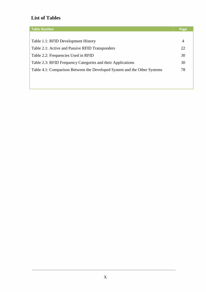
List of Tables Table Number Page
Table 1.1: RFID Development History
Table 2.1: Active and Passive RFID Transponders
Table 2.2: Frequencies Used in RFID
Table 2.3: RFID Frequency Categories and their Applications
Table 4.1: Comparison Between the Developed System and the Other Systems
4
22
30
30
78
XI
ABSTRACT
Contactless smart cards appeared several years ago in the form of electronic tags.
Today they are used in the fields of electronic ticketing, transportation and access
control. More recently they have started to be used for electronic payment transactions.
A contactless smart card is a smart card that can communicate with other devices
without any physical connection but by using Radio Frequency Identifier (RFID)
technology.
What are the advantages of contactless payments over other methods of payment
magnetic stripe cards and cash? Why are traders moving to deploy this new form of
payment? Why are consumers willing to change the way they pay? The answer is speed,
convenience, and security techniques.
The system that implemented in this thesis used the idea of card based payment
systems to bringing a cashless society, this achieved through using the contactless card
payment system. As a case study, we implement the system in the Middle East
University Cafeteria, and can be extended in future to cover all other payment services.
The system is improving the security and will success tackling the problems of fraud,
which gives greater confidence for using the system. In addition, it uses biometric
techniques (such as fingerprints) to clarifying the candidates and authenticates the user
prior to making a purchase.
XII
ا�����
���ة ا������ت ا��آ�� ا������� ��أت ���� �ر ��� .��ات ��$ #�" �����ت ا��! و
و/. . /. 5�� ا�(��.، *4!��م ا������ت ا��آ�� �+�2 ا�!�اآ ا��1! و���، و/. و��-, ا�+" و*(�) ا��'�ل
����6ت ا��/�7ت ا�����6 ./ � .ا9و�� ا8'� ة ��أ أ�!��ا
� ا������ت ا��آ�� ا�������� ه. �����ت ذآ�� ��درة ��$ ا�A*8ل ��8@ ?ة ا8' ى ��ون أي *�6س �" إ
.*4!��م *+�� 7ّ ف * دد ا� اد5�
� ه. ?ا�5 G� ؟ ا�+��5وI 5+� ا��/H66 2�� ا������ت آ��' ى ���/2 ا8���-" ا� �����ت ا��/2 ا��آ��
G �عا�!�Mر �L ه�ا ا� !( ك�6�5ذا �5�Mق ا� I�6ذا �/2؟ا�� �M�ا�46! ���ن ��$ ا�!�7اد �!��H ا�� 5+� ا�!.
( *�5 !L � .ه� ا�4 �� ، وا� ا�Q ، وا�!+��ت ا8�� ا�M�اب ؟7/�5�ن �
�R 2/ل ا���M��$ /� ة أ���6 ����� ا��/2 �����ل ا�$ 75!�6 �Qو I8ا Sه� ./ T��6م ا���أن ا�
�T5 I G أ�!��ا T+)!5 +�ي، وه�ام �����ت ا��/2 ا������� ا�������م ا�! دد ا� اد5�ي(م .(
./ S 5��* G�66ا� Gو*) *���T ه�ا ا���م آ(��� درا��� /. @��7 ا�L ق ا8و�, دا'" ا���/�!� �5، و
�7�Mا8' ى و@2�6 ا��4م ا� �W�!�6ت ا��/2 ا���' 2�6@ ���H!� "�+!46ا�.
. و���M��76� [M ا��L6آ" وآZL اQ8!��ل، Y .�7�� �6+� أن ا���م 675" ��$ *(G�4 ا��2X ا8
���ZL وا�
1
Chapter 1
Introduction
1.1 Overview
Contactless smart cards appeared several years ago in the form of electronic tags.
Today, they are typically used in the fields of electronic ticketing, transportation and
access control. More recently they have started to be used for electronic payment
transactions.
The main difference between contact and contactless cards is that the user does
not need to insert his contactless card into the slot of a smart card reader.
A contactless smart card is a smart card that can communicate with other devices
without any physical connection but by using Radio Frequency Identifier (RFID)
technology. The communication takes place via a radio frequency link, over the air,
rather than through electrical contacts located on the smart card module. An antenna
providing inducted current to the embedded smart card chip powers the whole system,
which is normally hidden between the front and the rear of the card body and is thus
invisible to the user (Handschuh, 2004).
Contactless smartcards are becoming increasingly popular with applications like:
credit-cards, national-ID, passports, and physical access.
Contactless cards are a key technology for improving the consumer experience
for retail transactions. Both computational speed and RF sensitivity are factored into the
consumer’s perceived transaction time (Cook et al., 2007).
2
Contactless cards will examine rapidly growing market and it will provide an
overview of the most recent developments with presentations that spanning the wide
range of sectors in which contactless cards and technology are being developed and
employed.
The term contactless smart card refers to identification cards (for example, some
credit cards) that do not need to make contact either with the reader to be read, or to be
swiped in a special slot. The Contactless Smart Card capability is implemented by using
a tiny RFID tag in the card; the intent was to provide the user with greater convenience
by speeding checkout or authentication processes (Technovelgy, 2005).
RFID is not a new technology as most people think. The first use of RFID
system was in the 1940’s for distinguishing friendly aircraft from the enemy one, where
large powered RFID tags were placed on friendly aircraft, thus these tags would give
response to identify the carrying aircraft as ‘friendly’ when interrogated by a radar
signal. The system was called IFF (Identify: Friend or Foe) and the Modern Aviation
Traffic Control is still adopting its original concept. (Handschuh, 2004)
After that, the wheels of RFID development were turning. The 1950s were an era
of exploration of RFID techniques following technical developments in radio and radar
in the 1930s and 1940s. Work such as F. L. Vernon's "Application of the microwave
homodyne" and D.B. Harris’ "Radio transmission systems with modulatable passive
responder" were important for development of RFID. (Cook et al., 2007)
3
The 1960s were the prelude to the RFID explosion of the 1970s, commercial
activities were beginning in the 1960s. Sensormatic and checkpoint were founded in the
late 1960s. These companies, with others such as Knogo, developed electronic article
surveillance (EAS) equipment to counter theft. EAS is arguably the first and most
widespread commercial use of RFID (Cook et al., 2007).
In the 1970s developers, inventors, companies, academic institutions, and
government laboratories were actively working on developing RFID.
The 1980s became the decade for full implementation of RFID technology,
though interests developed somewhat differently in various parts of the world. The
greatest interests in the United States were for transportation, personnel access, and to a
lesser extent for animals. In Europe, the greatest interests were for short-range systems
for animals, industrial and business applications, though toll roads in Italy, France,
Spain, Portugal, and Norway where were equipped with RFID.
The 1990's were a significant decade for RFID since it saw the wide scale
deployment of electronic toll collection in the United States. The world's first open
highway electronic tolling system opened in Oklahoma in 1991, where vehicles could
pass toll collection points at highway speeds, unimpeded by a toll plaza or barriers and
with video cameras for enforcement. The world's first combined toll collection and
traffic management system was installed in the Houston area by the Harris County Toll
Road Authority in 1992. Interest was also taken for RFID applications in Europe during
the 1990s. Both Microwave and inductive technologies were finding use for toll
collection, access control and a wide variety of other applications in commerce. (Cook et
al., 2007).
4
Table 1.1 summarizes the RFID development history.
Table 1.1 RFID Development History
Decade Event
1940 - 1950 Radar refined and used. Major World War II development effort. RFID
invented in 1948.
1950 - 1960 Early explorations of RFID technology, laboratory experiments.
1960 - 1970 Development of the theory of RFID. Start of applications field trials.
1970 - 1980 Explosion of RFID development. Tests of RFID accelerate.
Very early adopter implementations of RFID.
1980 - 1990 Commercial applications of RFID enter mainstream.
1990 - 2000 Emergence of standards. RFID widely deployed. RFID becomes a part of
everyday life.
Nowadays the world of payments and security is changing and new technologies
are revolutionizing the way consumers interact with retailers and the way they pay for
goods. Also, the rate of change is increasing with recent developments including a new
mobile payment service, contactless card trials, and many other innovations.
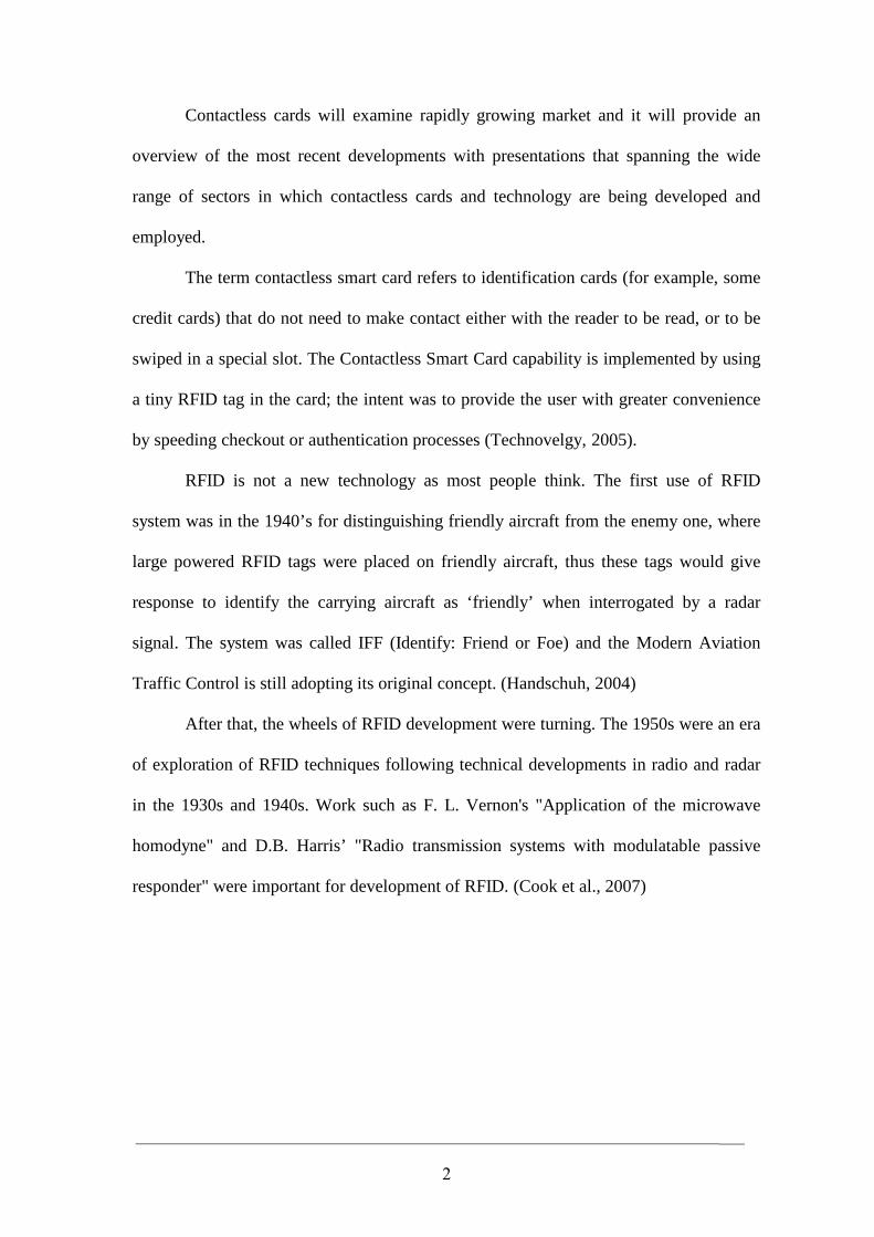
There are different types of smart cards. They are classified into:
Contact smart cards, contactless smart cards, and hybrid (combined) smart cards as
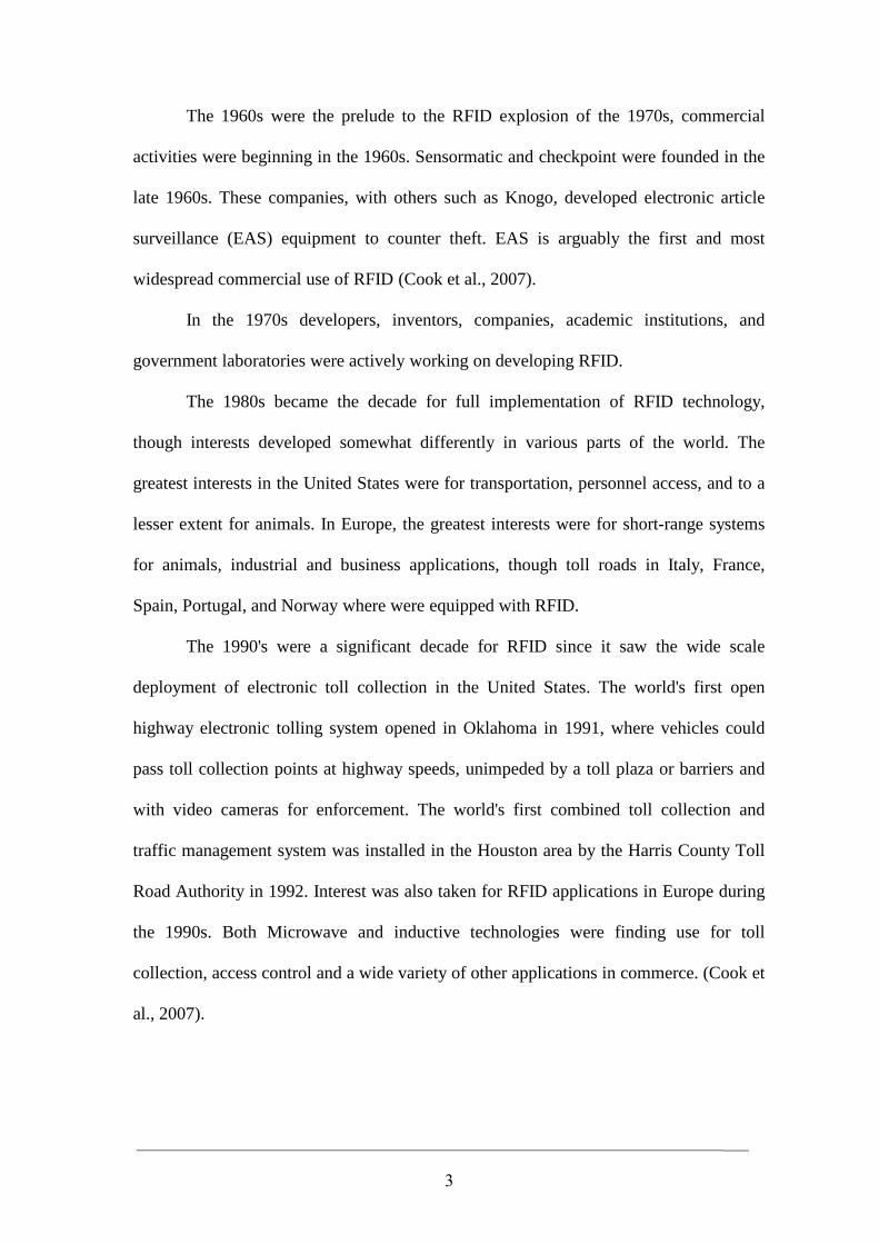
shown in Figure 1.1, Figure 1.2 shows a contactless smart card reader with its computer
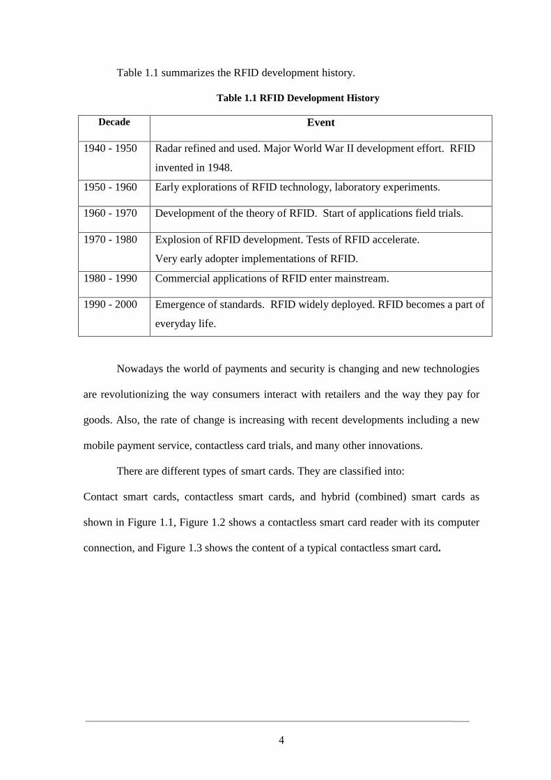
connection, and Figure 1.3 shows the content of a typical contactless smart card.
5
Contact Smart Cards Contactless Smart Card Hybrid (Combine) Smart Cards
Figures 1.1 Types of Smart Cards
Figure 1.2 Contactless Smart Card Reader with its Computer Connection
Figure 1.3 Content of a Typical Contactless Smart Card
Integrated Circuit
Highly flexible Antenna → ←
6
1.2 Problem Definition
For many years the notion of a cashless society has seemed to be drawing ever
closer while around the world coins and banknotes are used as payment in increasingly
few transactions as more and more systems present themselves not only as viable, but as
potentially better alternatives. A new generation of smart cards is being produced as
‘stored value cards’ which further reduces the instances in which physical cash is used in
making payments.
The change in using this technology shows that stored value card systems can be
successfully implemented, and accepted by the public. The advancement of RFID
system has seen smart card systems gain popularity in the different services, and it
seems perfectly plausible that such schemes will develop in the future to provide
multiple functionalities, such that one card can be used to make payments in different
services.
There are many perceived advantages to a cashless society, which is likely to
cause an increased usage of alternative payment methods in the years to come.
Improvements to security techniques may be successful in tackling the problems of
fraud, and give greater confidence in such systems. In the future, biometric techniques
are a clear candidate to authenticate a user prior to making a purchase.
The developed system tries to implement the usage of the idea of card based
payment systems in bringing about the future of a cashless society. This is going to be
achieved through using the contactless card payment system, which enables a decline in
cash payments.
Today, in Middle East University, they use the cash payment method in every
procedure inside the university, where this method has many problems, therefore if we
adopt contactless card payments system in converting this method then it’s going to be
7
more useful and effortless in every department, as well as if we compare its benefit with
credit cards that need a slot to be swiped in and it is not sufficiently secured. Here are
some problems of the two kinds of payment systems, cash payment and credit cards with
a slot:
Slowness is one of the problems that make the current payment systems
inefficient for example the cash transaction take 34 seconds and the magnetic strip card
transaction take 25 seconds (Rankl & Effing, 2003), especially when there are many
customers in the market and they are waiting in a casher queue, shall acquire a long time
before finalizing their payment.
Also the current payment systems similar to contact credit cards are very risky
where the account number can be easily exposed as it is shown in the cover of the card,
and the password is required to be entered.
The traditional cash payment is also not secured at all, you cannot carry more
cash money with you everywhere you go, there are risks of losing it forever, but if you
use the card and the card is stolen you can call the supplier for your card and stop the
card immediately in the same time the money will remain in it, and after you make the
new card the money is going to transfer to it.
For all the above reasons, we know for sure that the best payments system we
can use is the contactless card payments system.
In this thesis, there is an introduction to a new technique added to the system,
when the card is stolen or lost you can send a short message service (SMS) from your
mobile contains the password of the card, thus the system will block the card
immediately. The card will be blocked and no one can use it even if he knows the
password. And you can purchase a new card, the new card will contain the same amount
of money before the card was stolen or lost.
8
1.3 Motivation
The growing market and the other requirements of the age, as the consistent
speediness, payment protection and other security issues, must get improved. Hence the
new payment system is being developed to enhance these issues.
1.4 Thesis Objectives
For many years the notion of a cashless society has seemed to be drawing ever
closer. Around the world coins and banknotes are used as payment in increasingly few
transactions as more and more systems present themselves not only as viable, but as
potentially better alternatives.
This thesis uses a payment automation system, this system provides service-
oriented enterprises with many benefits like: simplifies the interaction of users with
payment systems, allows the enterprise to customize the types of payment media and
adapt them for the different client characteristics, improves fare system by optimizing
information flows, increases security and fraud control, and decreases exploitation costs.
Contactless smart cards fulfill rather well availability of versatile payment devices,
supporting a variety of modes and customization parameters, development of processing
and communication mechanisms permitting us to reduce interaction to the minimum,
and development of mechanisms guaranteeing data and transactions security (Carmel et
al. 2005).
Therefore we use the contactless devices in our thesis and in addition to these
benefits the payment system based on contactless devices offer the following properties:
• Scalability: it is the ability to incorporate new payment functionalities means of
payment, communication systems, and clients.
9
• Security: it is the ability to detect wrong transactions, both fraudulent and caused
by technical or accidental failures.
• Maintenance easiness: it is the ability to detect and respond to operation failures
of its elements. Also, it is the ability of its physical and logical elements to be
easily updated.
• Robustness: it is the ability to work in adverse physical conditions, both due to
environmental reasons and to a massive and continued use.
• Speed: it is the ability to carry out every transaction that is required in order to
provide services access to the users at speeds that do not interfere with
productive organization activity.
• Plain interactivity: it is the ability to permit the users to easily employ the means
of access to the services.
1.5 Significance of the Study
With recent advances in wireless technologies, RFID becomes an important
enabling technology for logistics and supply chain management systems and beyond.
What are the advantages of contactless payments over other methods of payment
– magnetic stripe cards and cash? Why are traders moving to deploy this new form of
payment? Why are consumers willing to change the way they pay? The answer is speed
and convenience, as has been substantiated in the early implementations and in recent
market research. Consumers no longer have to fumble with cash and change or worry
about having enough cash for a purchase - they can place their contactless payment
device in close proximity to a reader and go. In most cases, they do not even have to
sign a receipt or enter a personal identification number (PIN).
10
As a result, traders see sales volumes increase and transactions speed up. Chase
has reported that time at the POS is reduced 30% to 40% and an American Express
study found contactless transactions to be 63% faster than cash and 53% faster than
using a traditional credit card.
Research also shows that consumers generally spend more per transaction when
they don’t use cash – with chase reporting a 20% to 30% increase over cash purchases.
Traders also enjoy lower costs, as a result of fewer requirements to handle cash, improve
operational efficiencies, and reduce maintenance required by contactless readers. In
merchant segments where speed and convenience are key to merchandising and
customer service, contactless payments also translate into improved customer
acquisition and retention.
By issuing secure contactless payment devices, financial service providers are
not only supplying consumers with a more convenient payment mechanism, they are
also increasing transaction volumes by replacing cash. In addition, service providers
who use this payment system will have a competitive advantage (A Smart Card Alliance
Contactless Payments Council, 2006).
On the other hand it gives the traders a pre-money on their pockets, where the
consumer will transfer their money to their accounts on the contactless cards which
mean cash money on the merchant accounts, so the traders can benefit from that money
even before any item sold.
The consumer will also have another advantage from the payment system where he
will save his money on an account (contactless smart card), so he will decrease his
expenses and keep his money in a safe place.
11
1.6 Thesis Organization
In addition to this chapter, the thesis includes four other chapters and an
appendix, in this section we will describe briefly the contents of thesis, chapters and an
appendix.
Chapter 2 devoted to discuss RFID technologies, RFID system's components
transaction which consist of Reader and Tag, the advantages of contactless card, the two
kinds of payment systems: point of sale with an employee and point of sale without
employee and the steps of using this points of sale, then this chapter will describes the
communication procedure between the transponder and the reader, what is the RFID
transponder and their components, shapes, sizes, power supply for the transponder and
their types, operation types. What are the RFID readers and their components, RFID
carrier frequencies, the standards that are used in RFID, the end of this chapter will
presents the previous systems.
Chapter 3 provides a general description of the procedures, processes and
activities of current system that are currently used in the Middle East University (as a
case study) in all departments. In addition, depicts and analyze the general description of
the developed RFID system in this thesis.
Chapter 4 describes the design steps and implementation of the developed RFID
system in detail, including the algorithms, flowcharts, parts of the developed RFID
system, and more.
Finally the summary, conclusion and recommended future work are presented in
chapter 5.
Our thesis includes also references, glossary of terms and an appendix.
12
Chapter 2
RFID Technologies and Related Work
2.1 Overview
Radio Frequency Identification (RFID) is an automatic identification technology
of the ability of wireless communication (read and write data without direct contact) and
without the necessity of line-of-sight.
Contactless cards examine rapidly the growing market and it is able to provide
an overview of the most recent developments with presentations spanning the wide
range of sectors in which contactless cards and technology are being developed and
employed (Market Research, 2006).
The event includes detailed case studies through leading industry players on the
latest opportunities, technologies and challenges within the market, including the
transport systems, operator networks, payment applications and passports and
Identification number (ID).
2.2 RFID System’s Components
RFID systems exist in countless variants, produced by many different
manufacturers, but RFID system consists mainly of the following components:
2.2.1 Reader (Transceiver)
This device is used to read and/or write data to RFID tags. Antenna could be
build inside the reader which is the channel between the tag and the transceiver that
control the systems data access and communication.
13
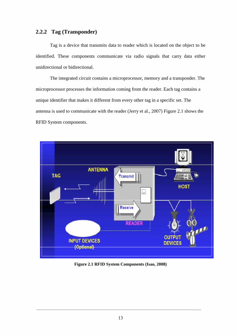
2.2.2 Tag (Transponder)
Tag is a device that transmits data to reader which is located on the object to be
identified. These components communicate via radio signals that carry data either
unidirectional or bidirectional.
The integrated circuit contains a microprocessor, memory and a transponder. The
microprocessor processes the information coming from the reader. Each tag contains a
unique identifier that makes it different from every other tag in a specific set. The
antenna is used to communicate with the reader (Jerry et al., 2007) Figure 2.1 shows the
RFID System components.
Figure 2.1 RFID System Components (Isao, 2008)
14
2.3 Transaction Time
From a consumer’s point of view the transaction time starts when the card is
pulled from the wallet and ends when he/she walks away from the cash register.
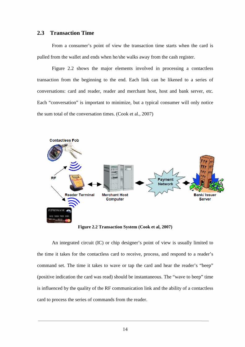
Figure 2.2 shows the major elements involved in processing a contactless
transaction from the beginning to the end. Each link can be likened to a series of
conversations: card and reader, reader and merchant host, host and bank server, etc.
Each “conversation” is important to minimize, but a typical consumer will only notice
the sum total of the conversation times. (Cook et al., 2007)
Figure 2.2 Transaction System (Cook et al, 2007)
An integrated circuit (IC) or chip designer’s point of view is usually limited to
the time it takes for the contactless card to receive, process, and respond to a reader’s
command set. The time it takes to wave or tap the card and hear the reader’s “beep”
(positive indication the card was read) should be instantaneous. The “wave to beep” time
is influenced by the quality of the RF communication link and the ability of a contactless
card to process the series of commands from the reader.
15
2.4 Advantages of Contactless Card
By issuing secure contactless payment devices, financial service providers are not
just supplying consumers with a more convenient payment mechanism; they are also
increasing transaction volumes by replacing cash traditional way of payment. In
addition, service providers who use this payment system will have a competitive
advantage (A Smart Card Alliance Contactless Payments Council, 2006).
In another hand, it gives the merchants a pre-money on their pockets, where the
consumer will transfer their money to their accounts on the contactless cards which
mean cash money on the merchant accounts, so the merchants can benefit from that
money even before any item sold. The consumer will also have another advantage from
the payment system where he will save his money on an account (contactless smart card)
and thus he decreases his expenses and keeps his money on a save place.
The reports for the credit card companies show that they are claiming the
following advantages for contactless credit cards:
Contactless Cards are Fast and Easy to Use
To make a purchase, the card owner just waves his card over the RFID reader,
waits for the acceptance indicator- and goes on his way. American Express, Visa and
Master Card have all agreed to waive the signature requirement for contactless credit
card transactions.
If you want to look at the numbers, here is where this technology is taking us in our
need for speed (average transaction speeds):
A. Contactless credit card transaction: 15 seconds.
B. Magnetic strip card transaction: 25 seconds.
C. Cash transaction: 34 seconds. (Carolyn, 2006)
16
Contactless Cards Use Highly Secured Data Transmission Standards
Contactless cards make use of the most secured encryption standards practical
with current technology. 128-bit and triple DES encryption make it nearly impossible
for thieves to steal your data (Technovelgy, 2005).
Contactless Card Never Transmits your Card Number
Instead, the RFID chip within the card creates a unique number for the
transaction; if a criminal intercepted the number, then it would be useless even if
successfully decrypted.
Contactless Cards Probably Use Other Measures
Although this is just speculation, there are certainly other ways to secure the data
on the card. For example, the RFID reader that sits on the merchant's counter may use
some sort of special signal, or offer a special set of frequencies, that would be difficult
for a thief with an off-the-shelf reader to duplicate.
More Memory and Higher Security
The contactless cards have internal RAM and there are many kinds of cards,
such as: 1KB RAM card, 4KB RAM card, and 16KB RAM card etc. and for that reason
it has a wider memory to store and higher security.
Provides Expanded Flexibility Over Magnetic Cards
17
2.5 Contactless Smart Cards and Payment Systems
In this thesis, the MIFARE contactless smart card and MIFARE card
reader/writer were discussed. It was developed to handle payment transactions for public
payment systems.
Although contact smart cards could also do the job, but by comparing the
contactless readers we find that they are faster and easier to use, and there is virtually no
maintenance on the readers, or wear and tear on the cards. MIFARE technology is
owned by Philips Electronics where they do not make cards or readers, but they make
and sell the card and reader chips in the open market.
In this thesis, we designed and implemented an essayer payment system that
requires minimal spare of efforts; the payment system will have two kinds of selling and
registering points.
1. Point of Sale with an employee.
2. Point of Sale without an employee.
2.5.1 Point of Sale with an Employee
This kind of point of sale use an employee, for helping the user paying for the
first time cost of the contactless card and the fee of registration and add credit.
2.5.2 Point of Sale without an Employee
These points of sale are going to consist of a touch screen only (no employee
required) that the user can:
1. Add credit.
2. Pay for a service.
3. Checking his/her account details and updating his/her file.
18
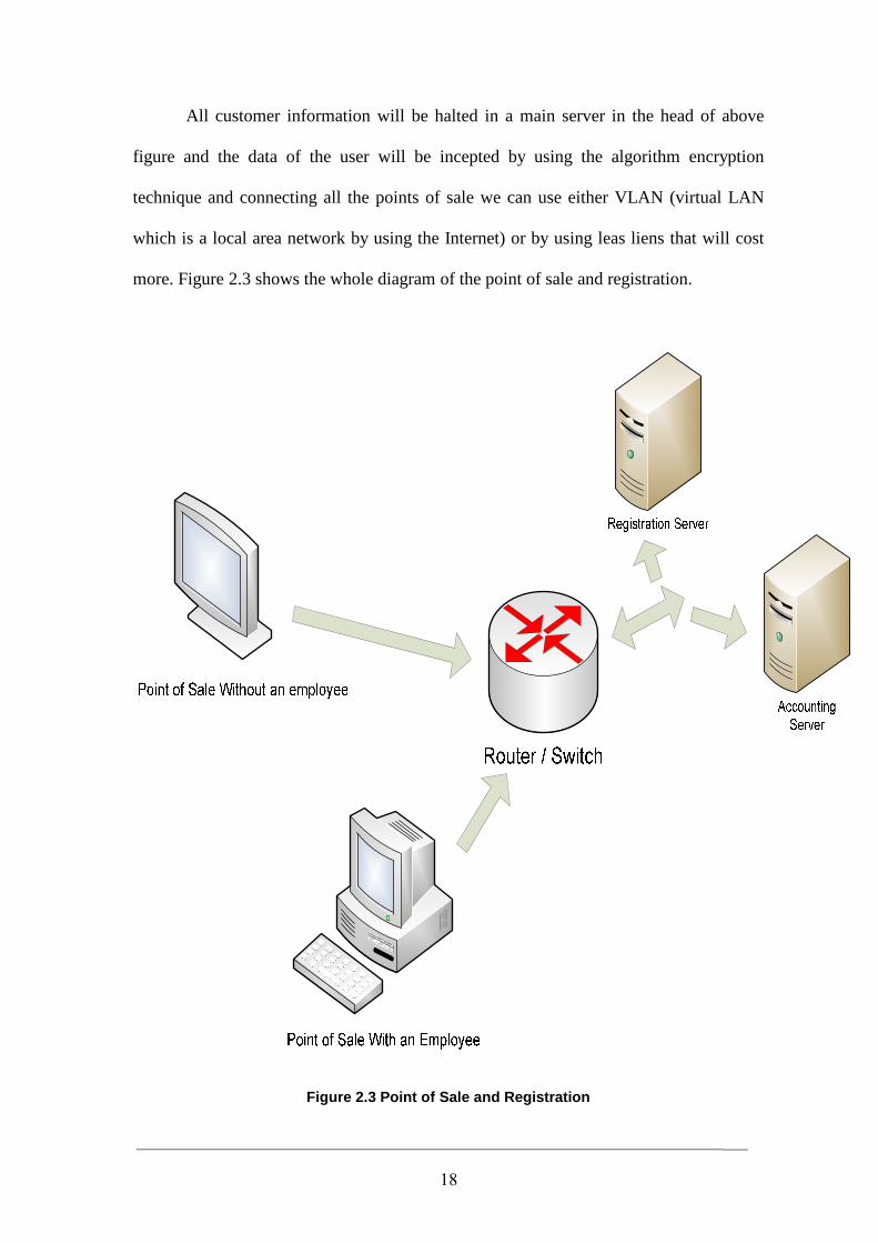
All customer information will be halted in a main server in the head of above
figure and the data of the user will be incepted by using the algorithm encryption
technique and connecting all the points of sale we can use either VLAN (virtual LAN
which is a local area network by using the Internet) or by using leas liens that will cost
more. Figure 2.3 shows the whole diagram of the point of sale and registration.
Figure 2.3 Point of Sale and Registration
19
2.6 Steps of Using Points of Sale
There are two steps as described below:
2.6.1 Point of Sale with an Employee
It is done like any old system, the user approaches to the point of sale and
requests from the employee what he wants. The employee will press the request for the
user and after the user will finish what they need, the employee will give him a print
documentation paper for all the user processes.
2.6.2 Point of Sale without an Employee
When the customer approaches to the point of sale device and the contactless
card is in range a welcome screen will appear requesting from the user a pin code. The
user inserts his information and then the user can use the system.
2.7 System Communication
Typical communication procedure between the transponder and the reader can be
highlighted as follows:
2.7.1 Handshake
1. The interrogator sends a command to start communication with transponder in the
interrogator field and also to power it (passive transponders).
2. Once the tag has received sufficient energy and command from the reader, it
replies with its ID for acknowledgment.
3. The reader now knows which tag is in the field and sends a command to the
identified tag for instructions either for processing (read or write) or sleep.
20
2.7.2 Data Exchange
1. If the tag receives processing and reading commands, it transmits a specified
block data and waits for the next command.
2. If the tag receives processing and writing commands along with block data, it
writes the block data into the specified memory block, and transmits the written
block data for verification.
2.7.3 Termination
1. After the processing, the interrogator sends an End command to send the tag into
the Sleep (“silent”) mode.
2. If the device receives an End command after processing, it sends an
acknowledgement (8-bit preamble) and stays in Sleep mode. During the Sleep
mode, the device remains in non-modulating (detuned) condition as long as it
remains in the power-up (Rao, et al., 2009).
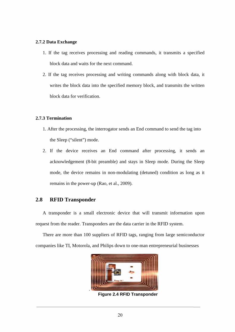
2.8 RFID Transponder
A transponder is a small electronic device that will transmit information upon
request from the reader. Transponders are the data carrier in the RFID system.
There are more than 100 suppliers of RFID tags, ranging from large semiconductor
companies like TI, Motorola, and Philips down to one-man entrepreneurial businesses
. Figure 2.4 RFID Transponder
21
2.8.1 Transponder Components
Basically, RFID transponders (tags) consist of an integrated circuit (IC) or a chip
attached to an antenna as shown in Figure 2.4.
Information about the physical object of the tag is stored on the IC/chip, while
antenna is responsible for receiving and transmitting data and recharging the transponder
(passive tags). Typically, these components are printed or encased on a thin plastic sheet
(Al-Mousawi, 2004).
2.8.2 Shapes and Sizes
RFID transponder comes in different construction formats, such as label-type,
card-type, coin-type, stick-type and many other types depending upon the application
and environment that will be used on. It can be as small as the head of a pin and as flat
as a sheet of paper.
2.8.3 Power Supply
Powering the RFID transponders is important to any RFID system. There are two
types of transponders which can be summarized as follows:
2.8.3.1 Active Transponders
These kinds of transponders have no need to be powered by the reader. Active
transponders have an integrated battery which supplies all or part of the needed power.
When the communication between the reader and the transponder starts, signals from the
reader will put the transponder in “wake up” mode. After completing the transaction
with the reader, the transponder will then return to the power saving “sleep” or “stand-
by” mode.
22
2.8.3.2 Passive Transponders
Passive transponders do not have any integrated power source and therefore are
totally dependent on reader’s (magnetic/electrical) field to get the needed power supply.
The transponder collects part of the energizing field via its antenna. Typically, passive
transponders are smaller and lighter than active ones, and less expensive. They are
maintenance free and will last almost indefinitely. In my thesis application program, I
will use this kind of transponders (passive transponders).
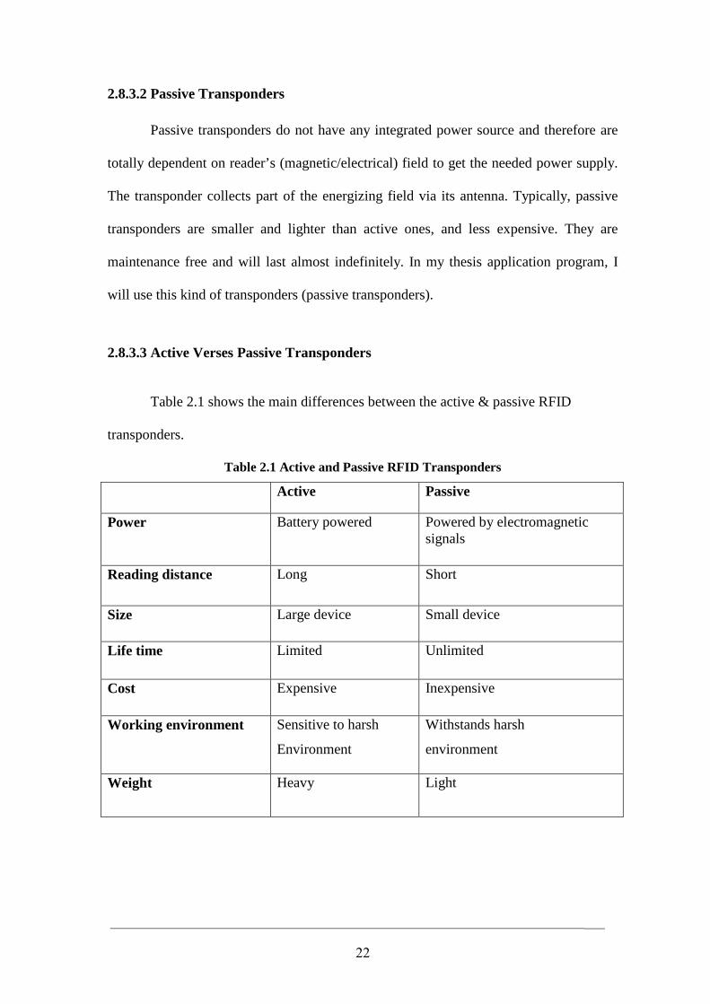
2.8.3.3 Active Verses Passive Transponders
Table 2.1 shows the main differences between the active & passive RFID
transponders.
Table 2.1 Active and Passive RFID Transponders
Active Passive
Power
Battery powered
Powered by electromagnetic signals
Reading distance Long Short
Size Large device Small device
Life time Limited Unlimited
Cost Expensive Inexpensive
Working environment Sensitive to harsh
Environment
Withstands harsh
environment
Weight Heavy Light
23
2.8.4 Operation Type
RFID systems operate according to one of two basic procedures, Full Duplex
(FDX), Half Duplex (HDX) systems or sequential systems (SEQ).
In full\half duplex systems, the transponder’s response is broadcast when the
reader’s radio frequency field is switched on. The transponder’s signal to the reader can
be extremely weak compared to the signal from the reader itself. Because of that
transmission procedures must be employed to differentiate the transponder’s signal from
the reader (Finkenzeller, 2004).
This means, in practice, that data exchange from transponder to reader using load
modulation, but also sub harmonics technique may be used for the reader’s transmission
frequency.
Sequential systems employ a system whereby the field from the reader is
switched off briefly at regular intervals. These gaps are recognized by the transponder
and used for sending data to the reader. The disadvantage of using this procedure is the
power loss to the transponder during the transmission break, which must be smoothed
out by the provision of sufficient auxiliary capacitors or batteries.
2.8.5 Data Quantity
The normal range for the data capacity of RFID transponders vary from few
bytes to several kilobytes. The only exception is so-called 1-bit transponders. 1-bit of
data is enough to describe the situation for the reader: “transponder in the field” or “no
transponder in the field”. These kinds of transponders are very cheap because there is no
need for electronic chip and for this reason enormous number are used in Electronic
Article Surveillance (EAS) to protect goods in shops and businesses (Al-Mousawi,
2004).
24
2.8.6 Data Carrier’s Memory Access
According to memory accessibility, there are two types of transponders:
2.8.6.1 Read‐Only Transponders
These transponders are programmed only once by the manufacturer. The
information in the memory (transponder ID) cannot be changed by any command once it
has been written. This kind of transponders has small memory and is not expensive.
2.8.6.2 Read/Write Transponders
On the other hand, read/write transponders can be reprogrammed by reader’s
commands. These transponders have large memory and more expensive than the Read-
Only transponders. Read/write transponders have three main procedures for storing and
managing the data.
• EEPROM (Electrically Erasable Programmable Read-Only Memory):
This procedure is dominant in many RFID systems. However, this has the
disadvantages of high power consumption during the writing operation and a limited
number of write cycles.
• FRAM (Ferromagnetic Random Access Memory):
FRAM are more used in isolated cases. FRAM’s read power consumption is
lower than the EEPROM by a factor of 100 and the writing time is 1000 times lower.
Manufacturing problems have hindered its widespread introduction onto the market.
• SRAM (Static Random Access Memory):
SRAM are used for data storage in microwave system which facilitate very fast
write cycles. The disadvantage of this procedure is that the data requires an
uninterruptible power supply from an auxiliary battery (active transponder).
25
2.9 RFID Reader
RFID reader has the responsibility to read, write and retransmit data to RFID
transponders (tags) without direct contact and in some cases powering when the
transponders are passive. Reading and writing operations to tags are based on master-
slave principle. Reader’s role could be master or slave, which depends on whom the
reader are communicating with.
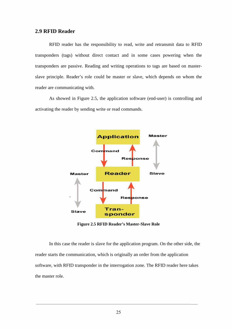
As showed in Figure 2.5, the application software (end-user) is controlling and
activating the reader by sending write or read commands.
Figure 2.5 RFID Reader’s Master-Slave Role
In this case the reader is slave for the application program. On the other side, the
reader starts the communication, which is originally an order from the application
software, with RFID transponder in the interrogation zone. The RFID reader here takes
the master role.
26
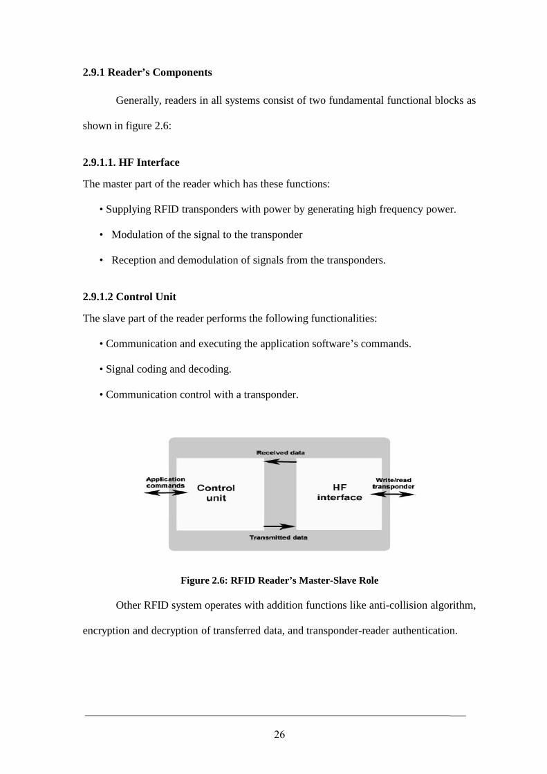
2.9.1 Reader’s Components
Generally, readers in all systems consist of two fundamental functional blocks as
shown in figure 2.6:
2.9.1.1. HF Interface
The master part of the reader which has these functions:
• Supplying RFID transponders with power by generating high frequency power.
• Modulation of the signal to the transponder
• Reception and demodulation of signals from the transponders.
2.9.1.2 Control Unit
The slave part of the reader performs the following functionalities:
• Communication and executing the application software’s commands.
• Signal coding and decoding.
• Communication control with a transponder.
Figure 2.6: RFID Reader’s Master-Slave Role
Other RFID system operates with addition functions like anti-collision algorithm,
encryption and decryption of transferred data, and transponder-reader authentication.
27
2.9.2 Data Transfer to Transponder
There are many types as follows:
2.9.2.1 Amplitude Shift Keying (ASK)
In amplitude modulation, high envelope is a ‘1’ and a low is a ‘0’. Amplitude
modulation can provide a high data rate but with low noise immunity.
2.9.2.2 Frequency Shift Keying (FSK)
This form of modulation uses two different frequencies for data transfer. FSK
allows for a simple reader design, provides very strong noise immunity, but suffers from
a lower data rate than some other forms of data modulation.
2.9.2.3. Phase Shift Keying (PSK)
This method of data modulation is similar to FSK except that only one frequency
can be used, and the shift between 1’s and 0’s is accomplished by shifting the phase of
the backscatter clock by 180 degrees. PSK provides fairly good noise immunity, a
moderately simple reader design, and a faster data rate than FSK. Because of the
simplicity of demodulation, the majority of RFID systems use ASK modulation (Pete
2002).
.
28
2.9.3 Types of Readers
Different applications have different requirements from each other, which results
to different designs of readers. Generally, readers are classified into the following three
types:
OEM Readers
OEM (Original Equipment Manufacturers) readers are mostly used for data
capture systems, access control systems, robots, etc.
Industrial Use Readers
Industrial readers are used in assembly and manufacturing plant.
Portable Readers
These readers are more mobile than the other readers which are supported with a
LCD display and keypad. Animal identification, device control and asset management
are some of uses for this kind of readers.
2.10 RFID Carrier Frequencies
RFID operates in several frequency bands. The RFID frequency for each country
is controlled by The Radio Regularity.
Most of the RFID frequencies that are used now are frequencies that have been
served specifically for industrial, scientific or medical application known as ISM
frequency ranges. RFID frequencies can be divided into the following three basic
ranges:
29
2.10.1 Low Frequency
The range of the low frequency RFID fluctuates a lot from a product to other
because the RFID producers do not have a standard. The range will find a place between
30 and 500 kHz. 134.2 kHz is the most ordinary used frequency that has been used for
the low frequency tags and readers.
Low frequency systems have short reading ranges and lower system costs. The
vast majority of the low frequency systems operate without the need of integrated
battery in their tags. They are most commonly used in security access, asset tracking and
animal identification applications. They are not too sensitive to metal, water and
electrical noise.
2.10.2 High Frequency
High frequency systems operate between 10 – 15 MHz, but a range of high
frequency RFID tags and readers operating mostly at 13.56 MHz (ISM frequency).
High frequency systems have longer read ranges and higher reading speeds than
the low frequency systems. The cost of this system is inexpensive, but higher than the
low frequency system. These systems are used in access control and smart cards.
2.10.3 Ultra High Frequency
An ultra high frequency system operates between 400 MHz to 1000 MHz and 2.4
GHz to 2.5 GHz. This technology is very expensive compared to the systems above.
This frequency range has a very long read range and a high reading speed. Unlike the
other systems, line of sight is required for the communication between RFID readers and
transponders. Ultra high frequency systems are used for such applications as railroad car
tracking and automated toll collection(Al-Mousawi, 2004)
30
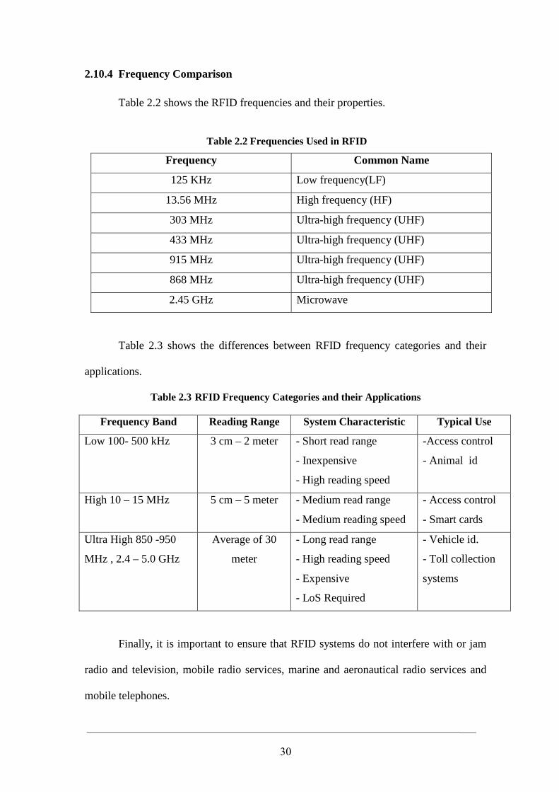
2.10.4 Frequency Comparison
Table 2.2 shows the RFID frequencies and their properties.
Table 2.2 Frequencies Used in RFID
Common Name Frequency
Low frequency(LF) 125 KHz
High frequency (HF) 13.56 MHz
Ultra-high frequency (UHF) 303 MHz
Ultra-high frequency (UHF) 433 MHz
Ultra-high frequency (UHF) 915 MHz
Ultra-high frequency (UHF) 868 MHz
Microwave 2.45 GHz
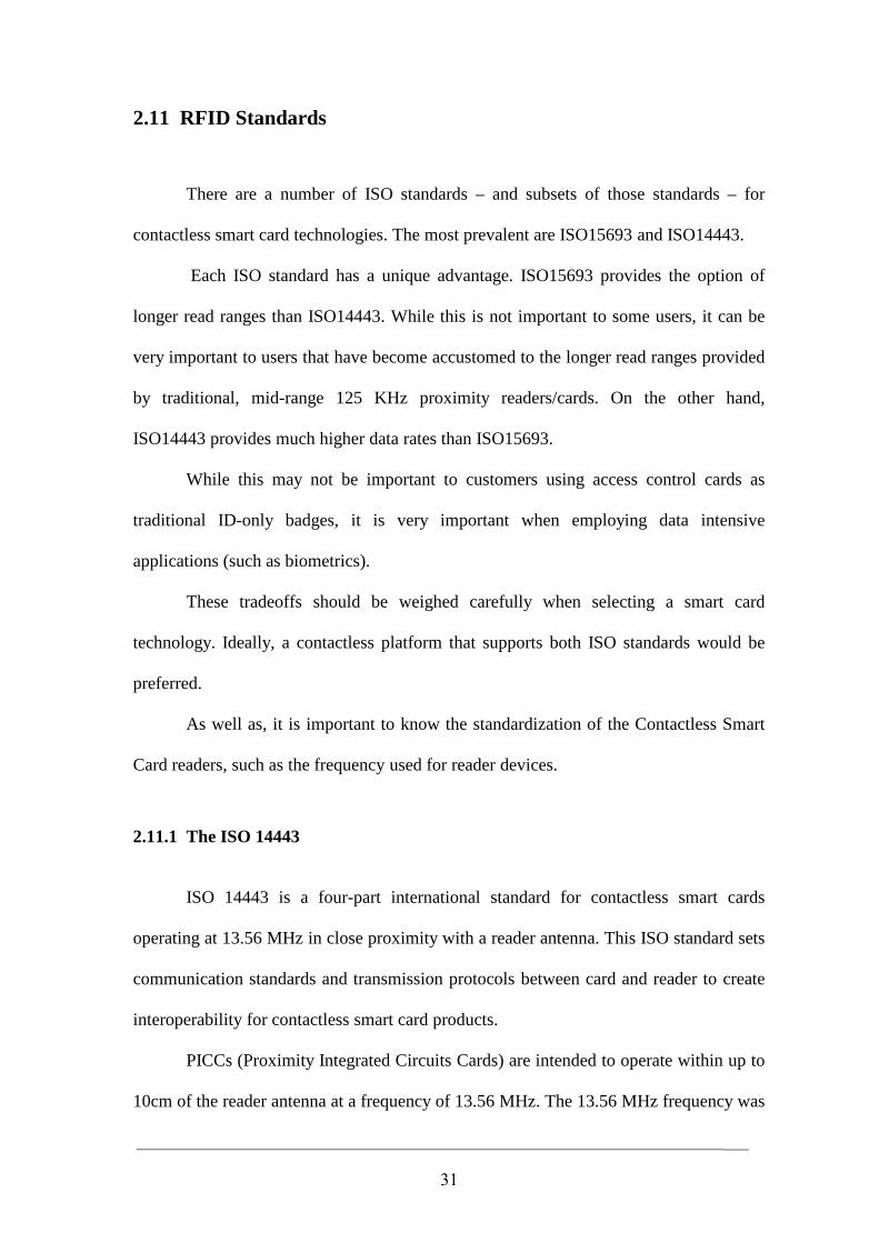
Table 2.3 shows the differences between RFID frequency categories and their
applications.
Table 2.3 RFID Frequency Categories and their Applications
Typical Use System Characteristic Reading Range Frequency Band
-Access control
- Animal id
- Short read range
- Inexpensive
- High reading speed
3 cm – 2 meter
Low 100- 500 kHz
- Access control
- Smart cards
- Medium read range
- Medium reading speed
5 cm – 5 meter
High 10 – 15 MHz
- Vehicle id.
- Toll collection
systems
- Long read range
- High reading speed
- Expensive
- LoS Required
Average of 30
meter
Ultra High 850 -950
MHz , 2.4 – 5.0 GHz
Finally, it is important to ensure that RFID systems do not interfere with or jam
radio and television, mobile radio services, marine and aeronautical radio services and
mobile telephones.
31
2.11 RFID Standards
There are a number of ISO standards – and subsets of those standards – for
contactless smart card technologies. The most prevalent are ISO15693 and ISO14443.
Each ISO standard has a unique advantage. ISO15693 provides the option of
longer read ranges than ISO14443. While this is not important to some users, it can be
very important to users that have become accustomed to the longer read ranges provided
by traditional, mid-range 125 KHz proximity readers/cards. On the other hand,
ISO14443 provides much higher data rates than ISO15693.
While this may not be important to customers using access control cards as
traditional ID-only badges, it is very important when employing data intensive
applications (such as biometrics).
These tradeoffs should be weighed carefully when selecting a smart card
technology. Ideally, a contactless platform that supports both ISO standards would be
preferred.
As well as, it is important to know the standardization of the Contactless Smart
Card readers, such as the frequency used for reader devices.
2.11.1 The ISO 14443
ISO 14443 is a four-part international standard for contactless smart cards
operating at 13.56 MHz in close proximity with a reader antenna. This ISO standard sets
communication standards and transmission protocols between card and reader to create
interoperability for contactless smart card products.
PICCs (Proximity Integrated Circuits Cards) are intended to operate within up to
10cm of the reader antenna at a frequency of 13.56 MHz. The 13.56 MHz frequency was
32
chosen for various technical reasons (e.g. suitability for efficient proximity compliance
and low absorption by human tissues.
Two main communication protocols are supported under the ISO 14443 standard
series Type A and Type B.
The ISO 14443 series define an “envelope protocol” that supports reliable, error-
free data transmission with multiple cards, but do not define the contents of the data.
ISO 14443 supports the exchange of standard ISO 7816 data packets, thus preserving the
industry investment in contact smart cards by allowing almost transparent and painless
application migration between contact to contactless environments.
As mentioned before, the ISO 14443 consists of the following parts:
Part 1: Physical characteristics
Part 2: Radio frequency power and signal interface
Part 3: Initialization and anti-collision
Part 4: Transmission protocols
The main key features of ISO 14443 can be summarized in the following points:
1- Operating frequency : Which is 13.56 MHz.
2- Read/write range : Up to 4 inches (10cm). Note: this figure is generally accepted
but it is not stated in the standard.
3- Speed : The ISO standard specifies a default speed of 106 Kbps, which
is mandatory for anti-collision stage. Higher communication, such as 212 Kbps and
higher, are allowed as an option.
4- Security
33
A. Wired logic cards: authentication mechanisms are available.
B. Microprocessor cards: security mechanisms available in contact smart cards are
also available for both ISO 14443 Type A and Type B.
C. Crypto coprocessors, such as 3DES, ECC and RSA, can be used, but they are not
defined in the ISO standard.
D. The close proximity of the card to the reader helps limit unintended
communication.
5- Interoperability : Supported through full definition of commands in ISO 14443 Part
4.
Currently, there are several enhancements to ISO 14443
1. Increased transaction speed: ISO 14443 standard already cater for optional higher data
rates of maximum theoretical speed of 847KBps. Type A, as is, is not suitable for such
higher data rates, so a mixed type A and B scenario has been proposed and is debated by
the ISO committee.
2. Testing: With each published standard ISO must also publish a standard set of
minimal test procedures that ensure the minimum accepted interoperability. For the ISO
14443 series, ISO is now developing ISO 10373 Part 6 that includes a set of test
procedures.
34
2.11.1.1 The Purpose of ISO 14443 Part 1
ISO 14443-1 was published as an international standard on April 15, 2000. The
standard defines the following:
- Card dimensions, referring to ISO 7810 standards for contact card size.
- Surface quality for printing.
- Mechanical resistance.
- UV and X-ray resistance.
- Sensitivity to surrounding magnetic fields.
- PICC: Proximity integrated circuit(s) card.
- PCD: Proximity coupling device (the card reader or terminal).
Part 1 defines the size and physical characteristics of the card. It also lists several
environmental stresses that the card must be capable of withstanding without permanent
damage to the functionality:
- Ultra-violet light.
- X-rays
- Dynamic bending and torsion stress
- Alternating magnetic and electric fields
- Static electricity and magnetic fields
The operating temperature range of the card is specified in Part 1 as an ambient
temperature range of 0°C to 50°C.
2.11.1.2 The Purpose of ISO 14443 Part 2
ISO 14443-2 was published on July 1, 2001. This standard describes the
characteristics of power transfer (based on inductive coupling) and communication
35
between the PICC and PCD. Power is transferred to the card using a frequency
modulated field at 13.56 MHz +/- 7 kHz.
Two different types of communication signal interfaces (bit modulation and
coding) are specified: Type A and Type B. The bit protocol timings are defined and the
default data transmission rate is defined at 106 K baud. Here are Some abbreviations
used in this standard are:
- ASK Amplitude Shift Keying.
- BPSK Binary Phase Shift Keying.
- NRZ Non-Return to Zero.
Part 2 defines the RF power and signal interface. Two signaling schemes, Type
A and Type B are defined in part 2. Both communication schemes are half duplex with a
default 106 kbps data rate in each direction. Data transmitted from the card to the reader
is achieved by utilizing load modulated with an 847.5 kHz sub carrier. The card is
powered by the RF field and no battery is required.
Differences between Type A and Type B include the modulation of the magnetic
field used for coupling, the bit and byte coding format and the anti-collision method
(i.e., how the cards and readers respond when more than one card responds at the same
time to a reader’s request for data). Type A has an ASK of 100% Reader to Card
modulation index, meaning that data is coded with short pauses in the transmission.
During these pauses no power is transmitted to the card. This dictates special
requirements to the chip in the card. Type A uses Modified Miller bit coding. Type B,
however, has an ASK of 10% Reader to Card modulation index, meaning that data is
coded with only minor reduction of its normal amplitude, enabling both card and reader
to maintain power throughout the communication process. This provides major
advantages compared with Type A. Type B uses NRZ bit coding.
36
2.11.1.3 The Purpose of ISO 14443 Part 3
ISO 14443-3 was published as an international standard on February 1, 2001.
This part of ISO 14443 describes:
- Polling for PICCs entering the field of a PCD (i.e., the terminal talks first).
- Byte format, command frames and timing.
- Request (REQ) and Answer To Request (ATQ) commands.
- Anti-collision methods to detect and communicate with one particular card when
several cards are presented to the same reader.
Anti-collision methods rely on a unique ID per card:
1. Type A: Binary search method referring to the unique identifier (UID) of the card.
2. Type B: Slotted Aloha method with special slot markers.
The initialization and anti-collision protocols for Type A and Type B. The anti-
collision commands, responses, data frame, and timing are defined in Part 3.
The initialization and anti-collision scheme is designed to permit the construction
of readers capable of communication with several cards of the same type, powered
simultaneously. Both card types wait silently in the field for a polling command. A
multi-protocol reader would poll one type, complete any transactions with cards
responding and then poll for the other type and transact with them. It is not assumed that
both types can be powered at the same time.
2.11.1.4 The Purpose of ISO 14443 Part 4
ISO 14443-4 was published as an international standard on February 1, 2001.
This standard specifies a half-duplex block transmission protocol (T = CL).This
standard, showing how this common transmission protocol can be used. The standard
also defines the transparent exchange of data, independent of the lower layers.
37
Part 4 defines the high-level data transmission protocols for Type A and Type B.
The protocols described in Part 4 are optional elements of the standard.
Part 4 deals mostly with the band rate negotiation between the card and the
reader, data encapsulation n block format, chaining (breaking a long block into smaller
ones) and error handling and recovery scenarios.
2.11.2 The MIFARE Standard
The MIFARE name covers two different kind of contactless cards:
1. MIFARE Classic and MIFARE Ultra Light Cards Standard.
2. MIFARE ProX, and SmartMX Cards Standard
2.11.2.1 MIFARE Classic and MIFARE Ultra Light Cards Standard
MIFARE Classic or Standards employ a proprietary high-level protocol instead
of ISO 14443-4, with a Philips proprietary security protocol for authentication and
ciphering. MIFARE UltraLight Cards employ the same protocol, but without the
security part.
The MIFARE Classic and MIFARE Ultra Light Cards are fundamentally just
memory storage devices, they are ASIC based and therefore have limited computational
power. Thanks to their low cost and reliability, those cards are widely used for electronic
wallet, access control, corporate ID cards, transportation or stadium ticketing.
The MIFARE Standard 1k offers about 768 bytes of data storage, split into 16
sectors; each sector is protected by two different keys, called A and B. They can be
38
programmed for operations like reading, writing, increasing value blocks, etc. MIFARE
Standard 4k offers 3 kb split into 64 sectors.
The MIFARE Ultra Light has only 512 bits of memory (i.e. 64 bytes), without
security. This card is so inexpensive, it is often used for disposable tickets.
2.11.2.2 MIFARE ProX, and SmartMX Cards Standard
MIFARE ProX and SmartMX, are NXP Semiconductors brand names for smart
cards that comply to ISO 14443-4. They are microprocessor based cards. The hardware
does nothing on its own, it has to be programmed with dedicated software in the
operating system. Most of the time, the microprocessor is coupled to a co-processor
dedicated to fast cryptographic computations (e.g., Triple DES, AES, RSA, etc.). These
Cards are capable to execute complex operations as secure and fast as known from
contact based cards, which includes Java based operating systems such as JCOP.
Depending on the installed software, the card can be used for almost any kind of
application. This kind of card is mostly used where a high level of security is required
(e.g., secure travel documents, electronic passports, payment card, etc.)
The MIFARE DESFire is a special release of Philips SmartMX platform. It is
already sold and programmed with a general purpose software (the DESFire operating
system) that offers more or less the same functions as MIFARE Standard (4kB data
storage split into 16 areas) but with higher flexibility, stronger triple-DES security, and
faster communication.
The typical read/write distance between card and reader is 10 cm (4 inches), but
actual distance depends on the field power generated by the reader and its antenna size.
39
2.12 Previous Systems
In this section, we will review a previous systems related to the problem of this
thesis. Here we identify and evalute current and past approches. Reviewing the
successes and/or limitations of the related work is important to avoid past mistakes,
taking advantages of previous successes, and most importantly, improving the solution
when applied. It also motivates interest in the work by demonstrating its relevance and
importance. Therefore, discussing the related work is a best way to compare our system
with other systems.
There is a lot of related work that discussed how contactless smart cards are
working, showing its security level and its method of payment. Also there are special
kinds of payment systems which are sold (ready to use), these kinds are designed for a
special purpose, e.g. the bus card used in Amman Transit Authorities fare cards, where
you can find a card reader machine inside the bus for one function only which is
deducting a certain amount in each process.
In the last decade, smart cards evolved from basic memory cards to complex
systems on chips with expanding processing power. This has opened the path to many
applications such as financial transactions, e-commerce, physical access control, health,
and transportation services (Dhem, 2001).
Education industry is one of the growing industries that have adopted smart cards
system where many universities are successfully facilitate the usage of it. Among the
most reputable universities that use smart card are: University of Cambridge, University
of Nottingham, University of Chicago and University of Exeter. In the following, we
will give a brief description for each of them, showing the strength and weakness points:
40
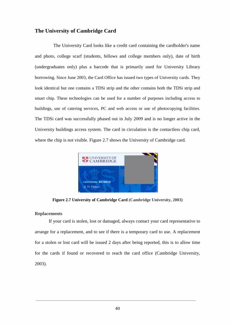
The University of Cambridge Card
The University Card looks like a credit card containing the cardholder's name
and photo, college scarf (students, fellows and college members only), date of birth
(undergraduates only) plus a barcode that is primarily used for University Library
borrowing. Since June 2003, the Card Office has issued two types of University cards. They
look identical but one contains a TDSi strip and the other contains both the TDSi strip and
smart chip. These technologies can be used for a number of purposes including access to
buildings, use of catering services, PC and web access or use of photocopying facilities.
The TDSi card was successfully phased out in July 2009 and is no longer active in the
University buildings access system. The card in circulation is the contactless chip card,
where the chip is not visible. Figure 2.7 shows the University of Cambridge card.
Figure 2.7 University of Cambridge Card (Cambridge University, 2003)
Replacements
If your card is stolen, lost or damaged, always contact your card representative to
arrange for a replacement, and to see if there is a temporary card to use. A replacement
for a stolen or lost card will be issued 2 days after being reported, this is to allow time
for the cards if found or recovered to reach the card office (Cambridge University,
2003).
41
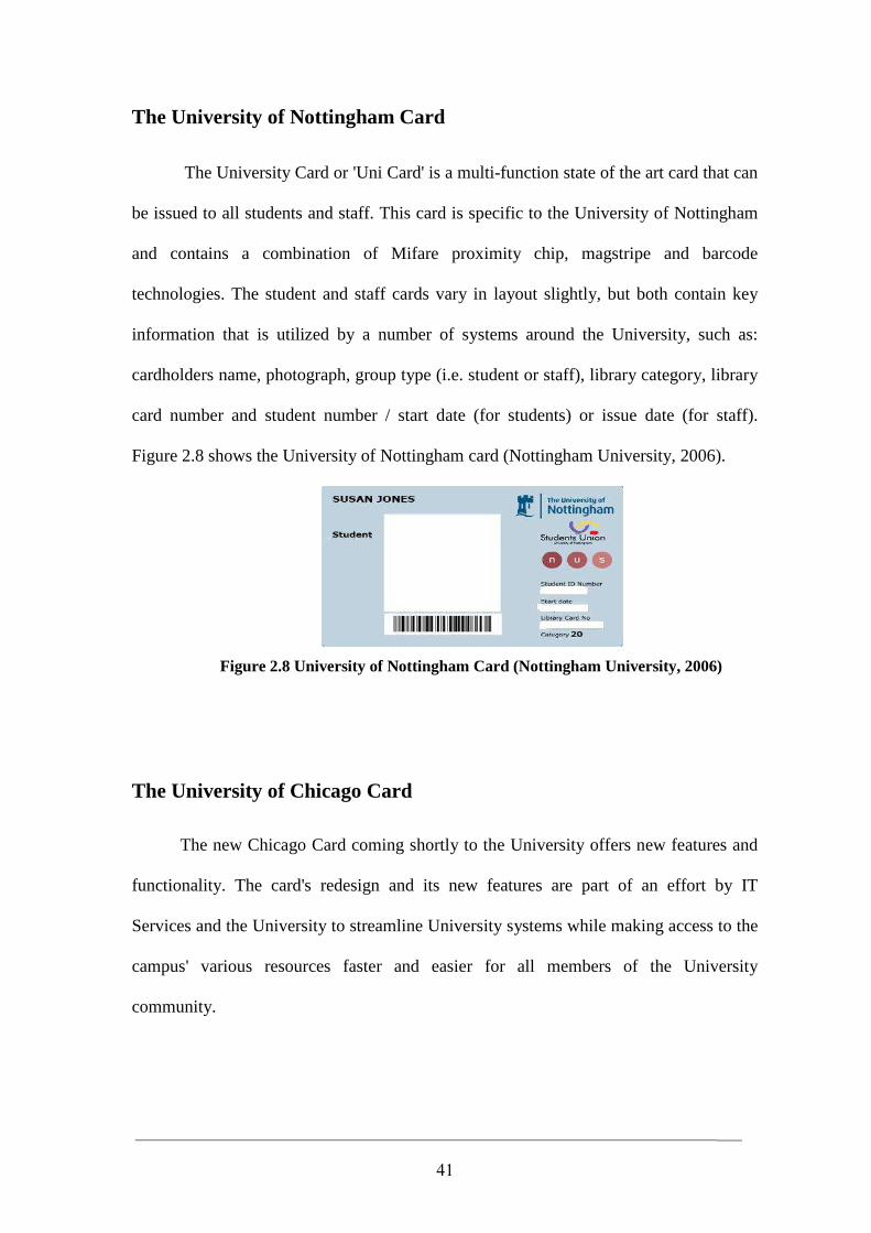
The University of Nottingham Card
The University Card or 'Uni Card' is a multi-function state of the art card that can
be issued to all students and staff. This card is specific to the University of Nottingham
and contains a combination of Mifare proximity chip, magstripe and barcode
technologies. The student and staff cards vary in layout slightly, but both contain key
information that is utilized by a number of systems around the University, such as:
cardholders name, photograph, group type (i.e. student or staff), library category, library
card number and student number / start date (for students) or issue date (for staff).
Figure 2.8 shows the University of Nottingham card (Nottingham University, 2006).
Figure 2.8 University of Nottingham Card (Nottingham University, 2006)
The University of Chicago Card
The new Chicago Card coming shortly to the University offers new features and
functionality. The card's redesign and its new features are part of an effort by IT
Services and the University to streamline University systems while making access to the
campus' various resources faster and easier for all members of the University
community.
42
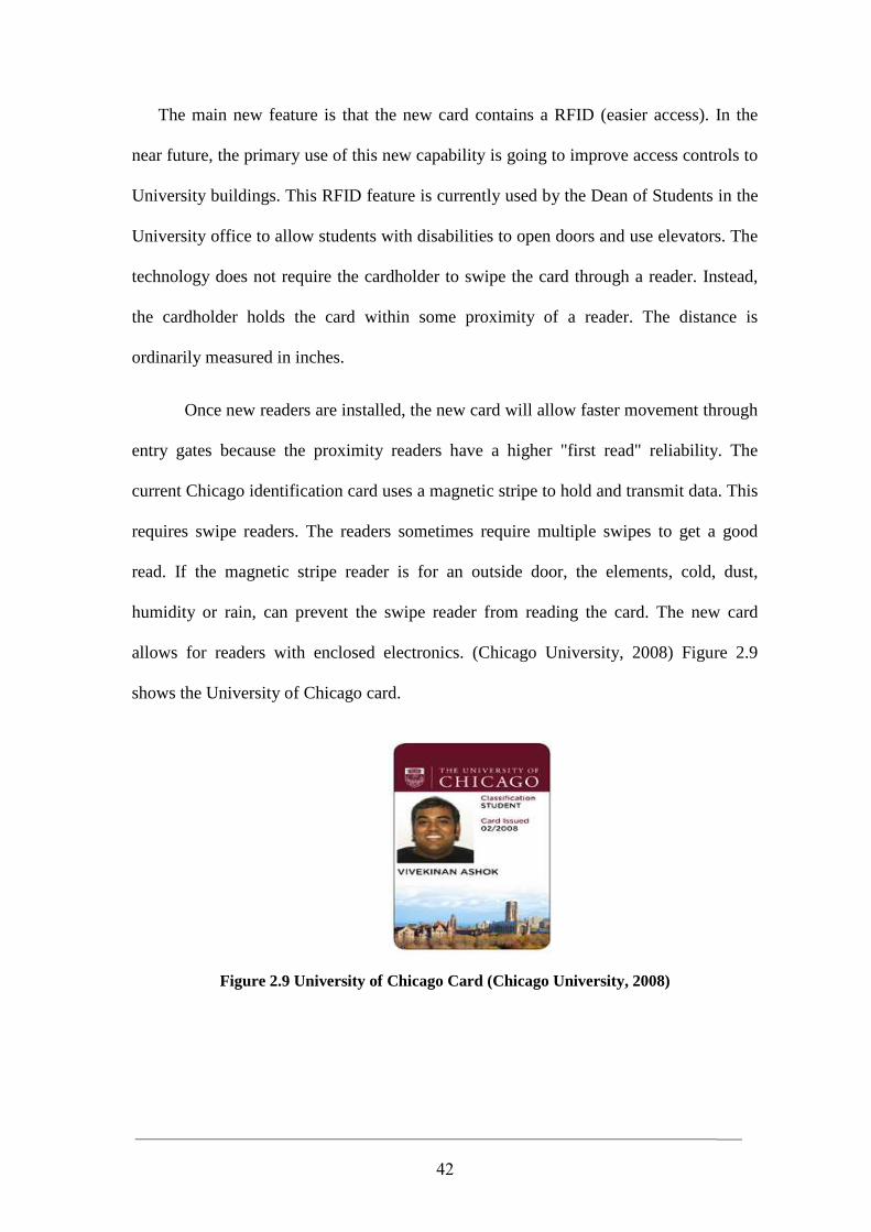
The main new feature is that the new card contains a RFID (easier access). In the
near future, the primary use of this new capability is going to improve access controls to
University buildings. This RFID feature is currently used by the Dean of Students in the
University office to allow students with disabilities to open doors and use elevators. The
technology does not require the cardholder to swipe the card through a reader. Instead,
the cardholder holds the card within some proximity of a reader. The distance is
ordinarily measured in inches.
Once new readers are installed, the new card will allow faster movement through
entry gates because the proximity readers have a higher "first read" reliability. The
current Chicago identification card uses a magnetic stripe to hold and transmit data. This
requires swipe readers. The readers sometimes require multiple swipes to get a good
read. If the magnetic stripe reader is for an outside door, the elements, cold, dust,
humidity or rain, can prevent the swipe reader from reading the card. The new card
allows for readers with enclosed electronics. (Chicago University, 2008) Figure 2.9
shows the University of Chicago card.
Figure 2.9 University of Chicago Card (Chicago University, 2008)
43
The University of Exeter Card
The UniCard is issued to all staff and students. The UniCard serves as your
Library card, identifies you as a member of the University and allows you appropriate
access to its services and facilities. Entitlement to University facilities varies according
to your University status. UniCards bear the user’s name and photo, expiry date and a
barcode with a number underneath it. The barcode/number is encoded on the reverse of
the card and this magnetic strip is used for building access control. The Unicard also
carries the University of Exeter logo. Lost, stolen or damaged cards: If your UniCard is
lost or stolen, please notify the card office immediately (Exeter University, 2008).
44
Chapter 3
Analysis of the Developed System
3.1 Overview
System analysis is the process of examining a business situation for the purpose
of developing a system solution to a problem or devising improvements to such a
situation. In order to develop any system, the first essential step is to make a
comprehensive and detailed analysis of the current system to develop a quality and new
information system.
Therefore, this chapter provides general descriptions of the procedures, processes
and activities of the current system which is currently used in the Middle East University
(MEU) as a case study in all departments. Besides, depicts and analyzes a general
description of the developed RFID system in this thesis.
3.2 Analysis of Current System in the MEU
This section will describe, in detail, the processes and procedures that are
currently used in MEU. MEU has many departments, each department consists of one or
more branches, these branches require information about each and every students
belongs to it.
When a new student wants to register in the university, at the beginning he/she
goes to the Financial Department and pay the required fees for registration (determined
from the financial department) and take the student number which is unique and use it as
a primary key in the current university database.
45
The Financial Department currently uses the traditional cash payment, and when
a new student wants to register for the new course, the procedure is going to be as
follows:
When the student wants to register for a new course, his first step must be
visiting the Admission and Registration Administrative (ARD), and take the registration
form No. 2, then write the desired subject, after that he/she must pay the fees in the
Financial Department (Cash Money) and stamp the registration form No. 2. The next
step must be visiting head of the department to sign the registration form and return back
again to the Admission and Registration Administrative (ARD) to complete the
registration process.
After finishing the registration, the student will take a letter from the Financial
Department as a proof for fulfilling his payment and a letter from the Admission and
Registration Administrative (ARD) contains the subjects that he/she registers for in the
coming course.
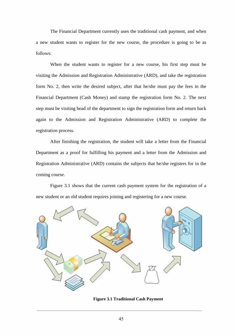
Figure 3.1 shows that the current cash payment system for the registration of a
new student or an old student requires joining and registering for a new course.
Figure 3.1 Traditional Cash Payment
46
Currently, all payments activities in the university is done manually such as:
1- Making a student ID card.
2- Buy a badge for the car to enter the university garage.
3- Rent out books from the library.
4- Dealing with the university cafeteria and supermarket.
All the above mentioned activities and other additional long procedure can be
solved by taking one step which is using the developed system only.
3.3 The System Development Life Cycle
There are many ways for developing an information system such a prototyping and
Systems Development Life Cycle (SDLC); both users and managers should know what
they want from the system. This means, the software requirements should be clearly
understood. We must develop our system using the SDLC, which consists of the
following phases/steps:
o Identification and Selection
o Initiation and Planning
o Analysis
o Design
o Implementation
o Maintenance.
47
3.3.1 Identification and Selection
3.3.1.1 Studying Existing System
After analyzing and studying the current system at the university and gathering
information from the specialists, we found many problems and weakness points in the
current used system processes. Therefore, we are obliged to overcome these problems in
the new developed system.
3.3.1.2 Studying the New System
The new developed RFID system is meant to overcome the problems arising by
the current running system, and working through developing a RFID system, which
increases the efficiency, security, reliability, etc…, and making sure of its usefulness for
all members in the university (student, employees, professors, etc..).
3.3.2 Initiation and Information System Planning
Mission Statement
Facilitating the everyday commonplace routine, where the student, the member
of the staff, and the management can perform every and any process in the university
simply, quickly, securely, and most of all efficiently.
Functions: Update system or make a new system.
Student register for a new course, print the schedule for the
course, add credit to the contactless card, etc….
Training and maintenance.
Data Entities: Students, faculty staff, employees, managers, server computers,
LAN, monitors.
Information Systems: Search system, lending system, calculation processing,
retrieve system.
48
3.3.3 Analysis
3.3.3.1 Feasibility Study
Tangible benefits worksheet: Networked RFID information system intends to
help us increasing system transparency, error reduction, increase speed of operation and
activities, new technology like search remotely, and many other benefits.
Intangible benefits worksheet: Networked RFID information system is helpful in
increasing employee morale, more rapidity information, improves statistical information
and charts that assist in decision-making, improve system security, and ability to recover
system.
One–time cost worksheet: At start of year 0 we are going to need a new
hardware, employees training, application software.
Recurring cost worksheet: In year 1 to 2 we are going to need application
software maintenance and new hardware.
3.3.3.2 Developed System Requirements
User’s requirements (person who uses the system): the user wants to do all the
processes in the university in an easy, secured, and speedy way. In addition, enabling the
user to get the best use of the system by building the system posses user friendly
interface.
The system should have a kind of validating through helping the user to discover
and correct most of the errors that will happen when they use the system. Finally, the
system should make all the necessary calculation for the user, with an easy and clear
interface.
49
Manager requirements: system must have a good security for all peoples that use
the system, this done by enabling each group to access data that is needed for them and
hiding the data and interfaces for others.
Hardware and software resource requirements: the system requires a fast
processor computer, to get high performance, LAN network and server. The current
software requirements are VB.net, SQL server, and WIN XP operating system.
In this thesis, we intend to create a complete RFID system at MEU. Everyone at
the university who has a RFID card (contactless card) a student, as a case study, who
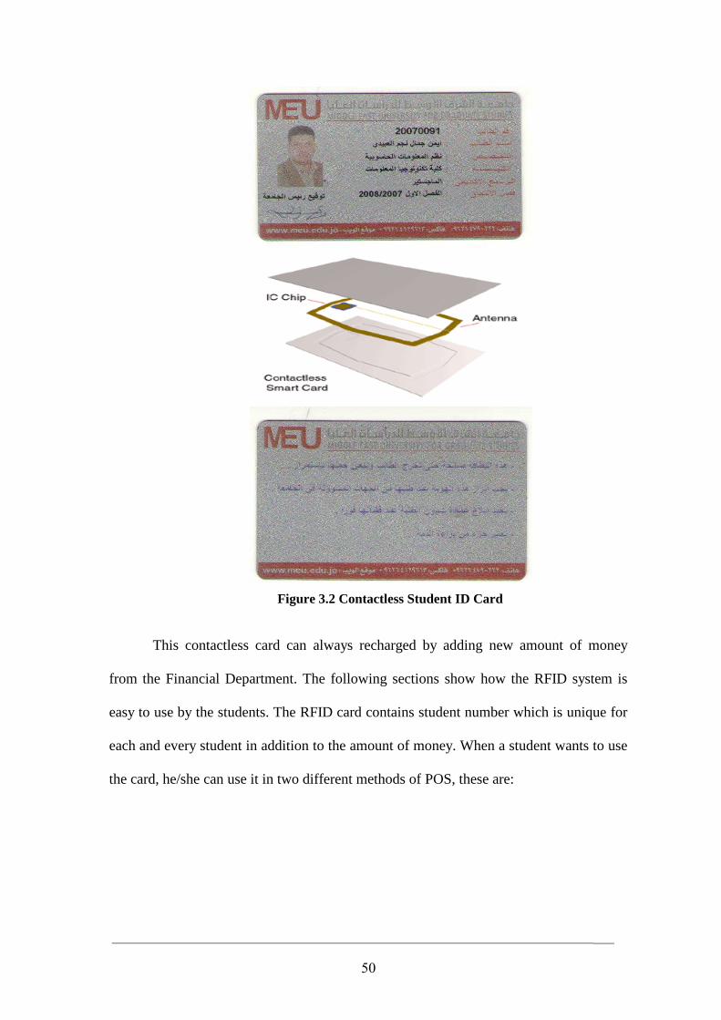
have a card. The card contains many details as show in Figure 3.2.
The contactless card must be charged by amount of money from the Financial
Department before using it. This amount of money is not fixed, it is different from one
student to another. It must hold a minimum of 1200 JD for the new student ( including
the first semester courses registration fee) and the remainder of the money can be used
in different activities at the university, for example to pay for the car badge, for the
cafeteria, and for the registration in every new course.
50
Figure 3.2 Contactless Student ID Card
This contactless card can always recharged by adding new amount of money
from the Financial Department. The following sections show how the RFID system is
easy to use by the students. The RFID card contains student number which is unique for
each and every student in addition to the amount of money. When a student wants to use
the card, he/she can use it in two different methods of POS, these are:
51
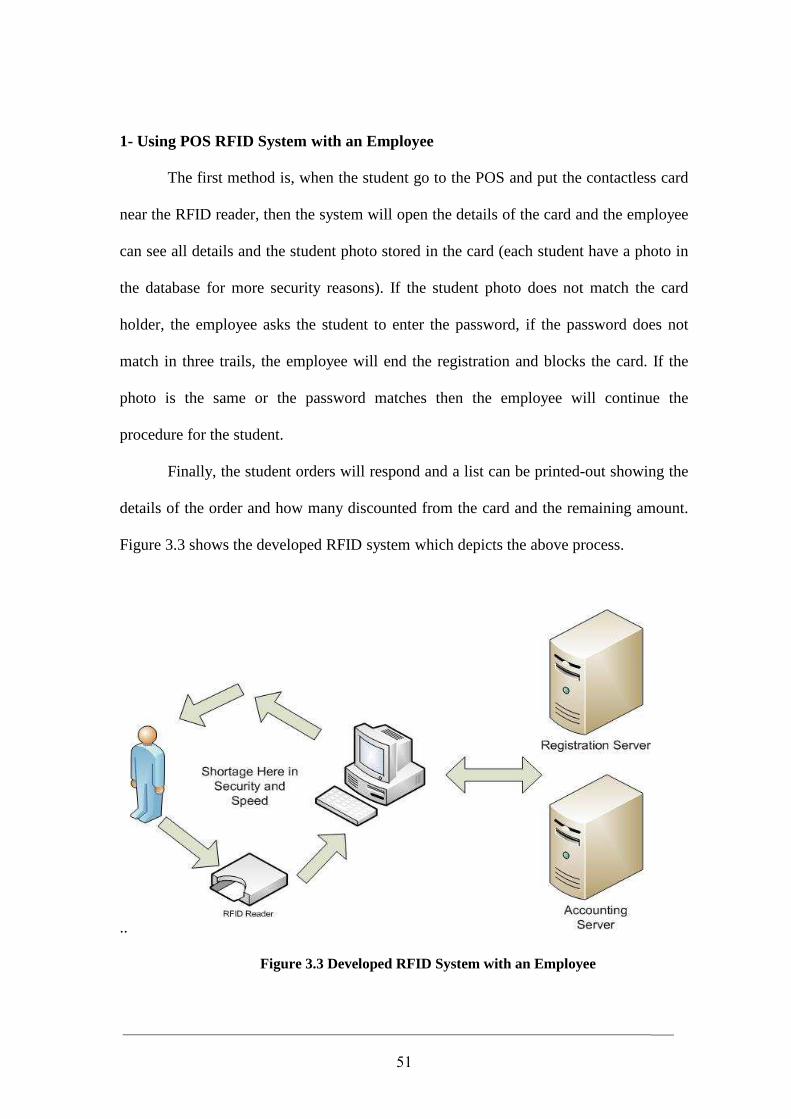
1- Using POS RFID System with an Employee
The first method is, when the student go to the POS and put the contactless card
near the RFID reader, then the system will open the details of the card and the employee
can see all details and the student photo stored in the card (each student have a photo in
the database for more security reasons). If the student photo does not match the card
holder, the employee asks the student to enter the password, if the password does not
match in three trails, the employee will end the registration and blocks the card. If the
photo is the same or the password matches then the employee will continue the
procedure for the student.
Finally, the student orders will respond and a list can be printed-out showing the
details of the order and how many discounted from the card and the remaining amount.
Figure 3.3 shows the developed RFID system which depicts the above process.
..
Figure 3.3 Developed RFID System with an Employee
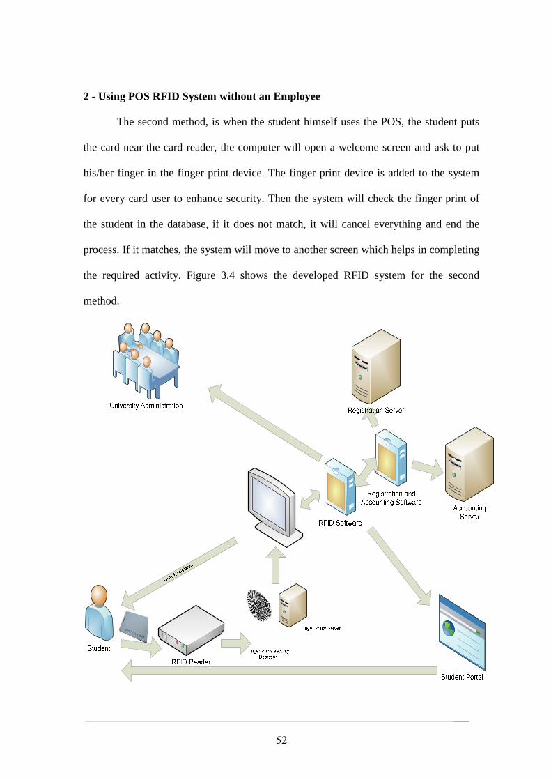
52
2 - Using POS RFID System without an Employee
The second method, is when the student himself uses the POS, the student puts
the card near the card reader, the computer will open a welcome screen and ask to put
his/her finger in the finger print device. The finger print device is added to the system
for every card user to enhance security. Then the system will check the finger print of
the student in the database, if it does not match, it will cancel everything and end the
process. If it matches, the system will move to another screen which helps in completing
the required activity. Figure 3.4 shows the developed RFID system for the second
method.
53
Figure 3.4 Developed RFID System without an Employee
Figure 3.4 shows a step-by-step usage of the developed RFID system. When the
student put the card nearest the card reader and puts its finger on the finger print device,
then the student can chose what they want from the system using the RFID software.
The RFID software will save all the activities of the registration in the server of the
registration department, or in the accounting server for the Financial Department. The
University administration has full authority to enter the database and see all these
procedures in event viewer.
For example, if the students require registration for a new course, the system will
complete the registration for the subjects, by guiding the student using a special user
friendly software and easy to use (wizard). The student can print out a bill before
completing and confirming the procedure (by click the confirm bottom) the system will
discount the money from the card and send the transaction to the financial department
server. Besides, it gives the student a printable report that contain the whole activities
that the student made for this process, like the amount of the money paid, the remaining
money in the card, the subjects that have registered for this course, the schedule, and all
other details.
3.3.3.4 The Users of the Developed RFID System
The developed system is very useful, and may be used by different members in
the MEU, these may be included in Figure 3.5.
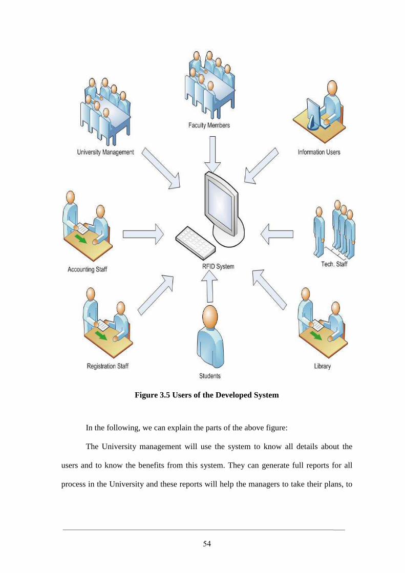
54
Figure 3.5 Users of the Developed System
In the following, we can explain the parts of the above figure:
The University management will use the system to know all details about the
users and to know the benefits from this system. They can generate full reports for all
process in the University and these reports will help the managers to take their plans, to
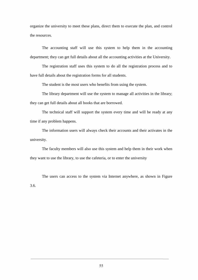
55
organize the university to meet these plans, direct them to execute the plan, and control
the resources.
The accounting staff will use this system to help them in the accounting
department; they can get full details about all the accounting activities at the University.
The registration staff uses this system to do all the registration process and to
have full details about the registration forms for all students.
The student is the most users who benefits from using the system.
The library department will use the system to manage all activities in the library;
they can get full details about all books that are borrowed.
The technical staff will support the system every time and will be ready at any
time if any problem happens.
The information users will always check their accounts and their activates in the
university.
The faculty members will also use this system and help them in their work when
they want to use the library, to use the cafeteria, or to enter the university
The users can access to the system via Internet anywhere, as shown in Figure
3.6.
Figure 3.6
As shown in the Figure 3.6, the whole developed R
the Internet. In this case, a proposed network design may read through many servers
(Database server, Application server, Web server, Network server) and firewalls for
optimum performance and security reasons.
56
Figure 3.6 Developed RFID System Linked to the Internet
As shown in the Figure 3.6, the whole developed RFID system can be linked to
the Internet. In this case, a proposed network design may read through many servers
(Database server, Application server, Web server, Network server) and firewalls for
optimum performance and security reasons.
nternet
FID system can be linked to
the Internet. In this case, a proposed network design may read through many servers
(Database server, Application server, Web server, Network server) and firewalls for
57
Chapter 4
Design and Implementation of the Developed System
4.1 Overview
This chapter explains, in detail, the design and implementation processes of the
developed system. This will be done through design and implementation of the pilot
system (which applied only in the Middle East University cafeteria) where we take the
pilot system as a case study in order to demonstrate the effectiveness of applying this
system. Furthermore, we can apply the same technology and components to provide
solutions for different applications in the other remaining University Departments such
as (Library, Registration Department, Financial Department …etc), as well as it can be
used, in general, at many other different public departments.
4.2 Developed System Design
System design is the process of defining the components, modules, interference,
architecture, and data for a system to satisfy specified requirements. In the following
subsection we will demonstrate the system design through different perspectives.
4.2.1 Flowchart of the Developed System
To understand how the system works precisely, we need to go through the
following diagram and track it from the start point that leads to the success or failure of
the process using the developed system. Figure 4.1 shows the flowchart of the developed
system.
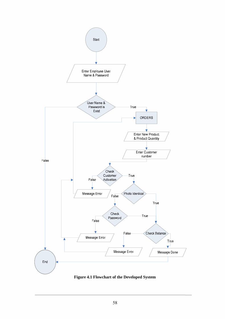
58
Figure 4.1 Flowchart of the Developed System
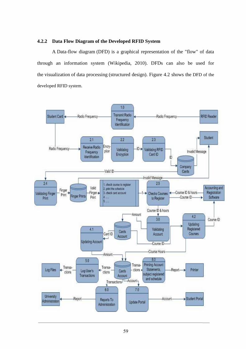
59
4.2.2 Data Flow Diagram of the Developed RFID System
A Data-flow diagram (DFD) is a graphical representation of the "flow" of data
through an information system (Wikipedia, 2010). DFDs can also be used for
the visualization of data processing (structured design). Figure 4.2 shows the DFD of the
developed RFID system.
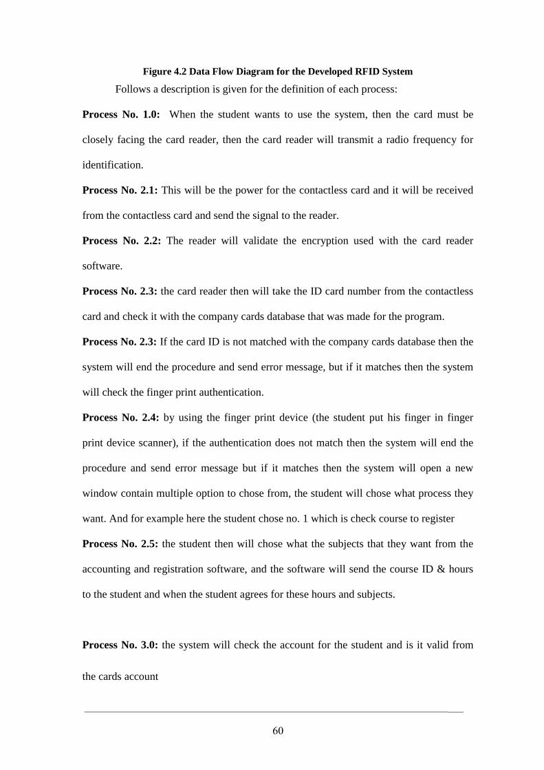
60
Figure 4.2 Data Flow Diagram for the Developed RFID System
Follows a description is given for the definition of each process:
Process No. 1.0: When the student wants to use the system, then the card must be
closely facing the card reader, then the card reader will transmit a radio frequency for
identification.
Process No. 2.1: This will be the power for the contactless card and it will be received
from the contactless card and send the signal to the reader.
Process No. 2.2: The reader will validate the encryption used with the card reader
software.
Process No. 2.3: the card reader then will take the ID card number from the contactless
card and check it with the company cards database that was made for the program.
Process No. 2.3: If the card ID is not matched with the company cards database then the
system will end the procedure and send error message, but if it matches then the system
will check the finger print authentication.
Process No. 2.4: by using the finger print device (the student put his finger in finger
print device scanner), if the authentication does not match then the system will end the
procedure and send error message but if it matches then the system will open a new
window contain multiple option to chose from, the student will chose what process they
want. And for example here the student chose no. 1 which is check course to register
Process No. 2.5: the student then will chose what the subjects that they want from the
accounting and registration software, and the software will send the course ID & hours
to the student and when the student agrees for these hours and subjects.
Process No. 3.0: the system will check the account for the student and is it valid from
the cards account
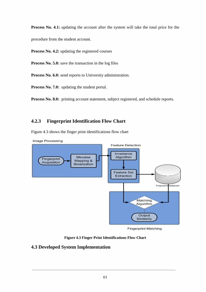
61
Process No. 4.1: updating the account after the system will take the total price for the
procedure from the student account.
Process No. 4.2: updating the registered courses
Process No. 5.0: save the transaction in the log files
Process No. 6.0: send reports to University administration.
Process No. 7.0: updating the student portal.
Process No. 8.0: printing account statement, subject registered, and schedule reports.
4.2.3 Fingerprint Identification Flow Chart
Figure 4.3 shows the finger print identifications flow chart
Figure 4.3 Finger Print Identifications Flow Chart
4.3 Developed System Implementation
62
This section will describe the implementation of the developed system through
explaining the tools required to build its components.
This developed system is implemented by using Visual Basic.Net programming
language and SQL Server for its consistent, which provides the developer with power of
many good features like user friendly interface and easy deployment and integrated with
other applications.
� Developed System Database
The developed system uses seven different tables which described as follows:
• Cards (Id, CardNo, RealCardNo )
• Customers(Id,CustNo, Name, Attachement, Active, Balance, StudentNo,
Mobile)
• Employee(Id, Name, Username, Password, Group_Num, Address, Attachment)
• GeneraldailyOrder (Id,GNumber, InvoiceNo, TotalPrice, CustNo)
• HistoryProduct(Id, Gnumber, ProdNo, CustNo, Qty, Mdate)
• Orders(Id, OrderNo, ProdNo, Gnumber, Qty)
• Product(Id, ProdNo, ProdName, ActualPrice, Price, Qty, SoldQty)
Figure 4.4 illustrates the developed system class diagram and its properties and
operations.
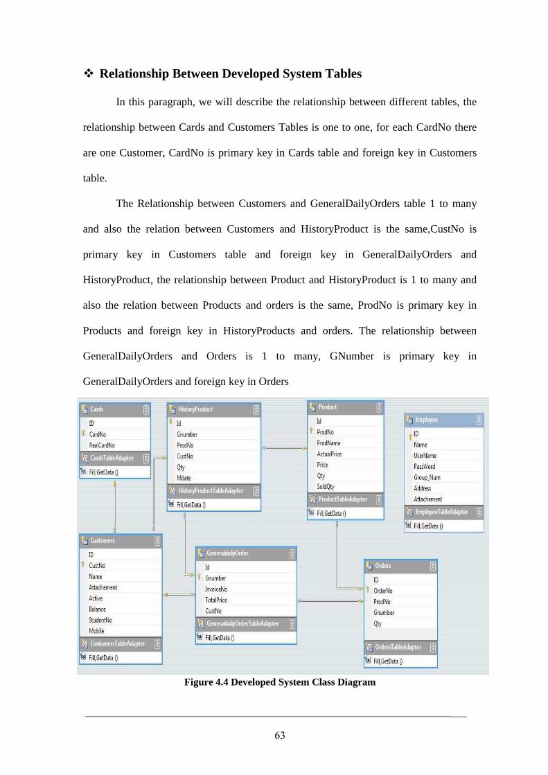
63
� Relationship Between Developed System Tables
In this paragraph, we will describe the relationship between different tables, the
relationship between Cards and Customers Tables is one to one, for each CardNo there
are one Customer, CardNo is primary key in Cards table and foreign key in Customers
table.
The Relationship between Customers and GeneralDailyOrders table 1 to many
and also the relation between Customers and HistoryProduct is the same,CustNo is
primary key in Customers table and foreign key in GeneralDailyOrders and
HistoryProduct, the relationship between Product and HistoryProduct is 1 to many and
also the relation between Products and orders is the same, ProdNo is primary key in
Products and foreign key in HistoryProducts and orders. The relationship between
GeneralDailyOrders and Orders is 1 to many, GNumber is primary key in
GeneralDailyOrders and foreign key in Orders
Figure 4.4 Developed System Class Diagram
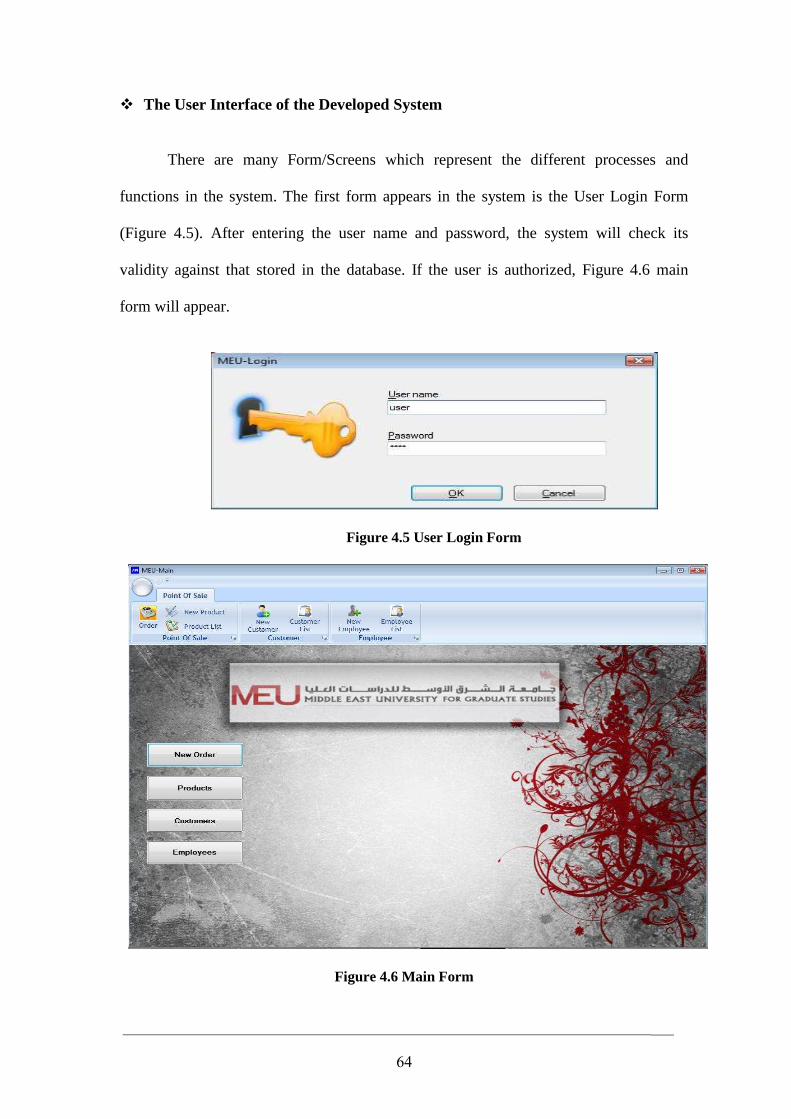
64
� The User Interface of the Developed System
There are many Form/Screens which represent the different processes and
functions in the system. The first form appears in the system is the User Login Form
(Figure 4.5). After entering the user name and password, the system will check its
validity against that stored in the database. If the user is authorized, Figure 4.6 main
form will appear.
Figure 4.5 User Login Form
Figure 4.6 Main Form
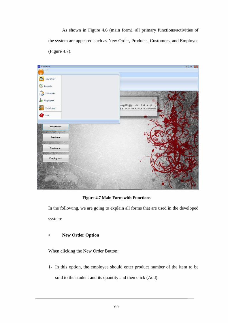
65
As shown in Figure 4.6 (main form), all primary functions/activities of
the system are appeared such as New Order, Products, Customers, and Employee
(Figure 4.7).
Figure 4.7 Main Form with Functions
In the following, we are going to explain all forms that are used in the developed
system:
• New Order Option
When clicking the New Order Button:
1- In this option, the employee should enter product number of the item to be
sold to the student and its quantity and then click (Add).
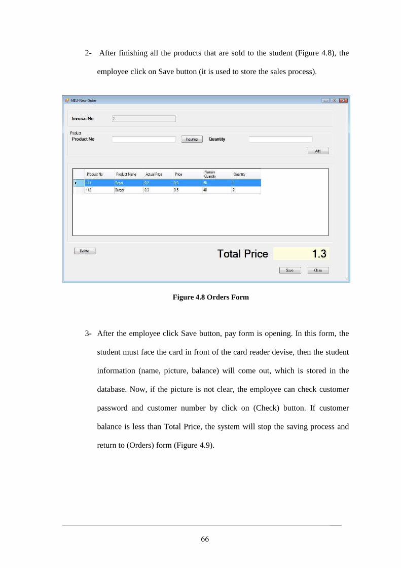
66
2- After finishing all the products that are sold to the student (Figure 4.8), the
employee click on Save button (it is used to store the sales process).
Figure 4.8 Orders Form
3- After the employee click Save button, pay form is opening. In this form, the
student must face the card in front of the card reader devise, then the student
information (name, picture, balance) will come out, which is stored in the
database. Now, if the picture is not clear, the employee can check customer
password and customer number by click on (Check) button. If customer
balance is less than Total Price, the system will stop the saving process and
return to (Orders) form (Figure 4.9).
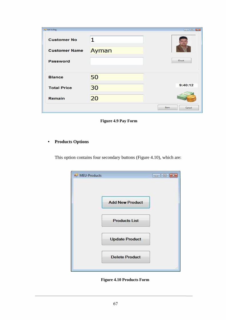
67
Figure 4.9 Pay Form
• Products Options
This option contains four secondary buttons (Figure 4.10), which are:
Figure 4.10 Products Form
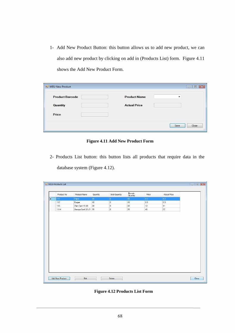
68
1- Add New Product Button: this button allows us to add new product, we can
also add new product by clicking on add in (Products List) form. Figure 4.11
shows the Add New Product Form.
Figure 4.11 Add New Product Form
2- Products List button: this button lists all products that require data in the
database system (Figure 4.12).
Figure 4.12 Products List Form
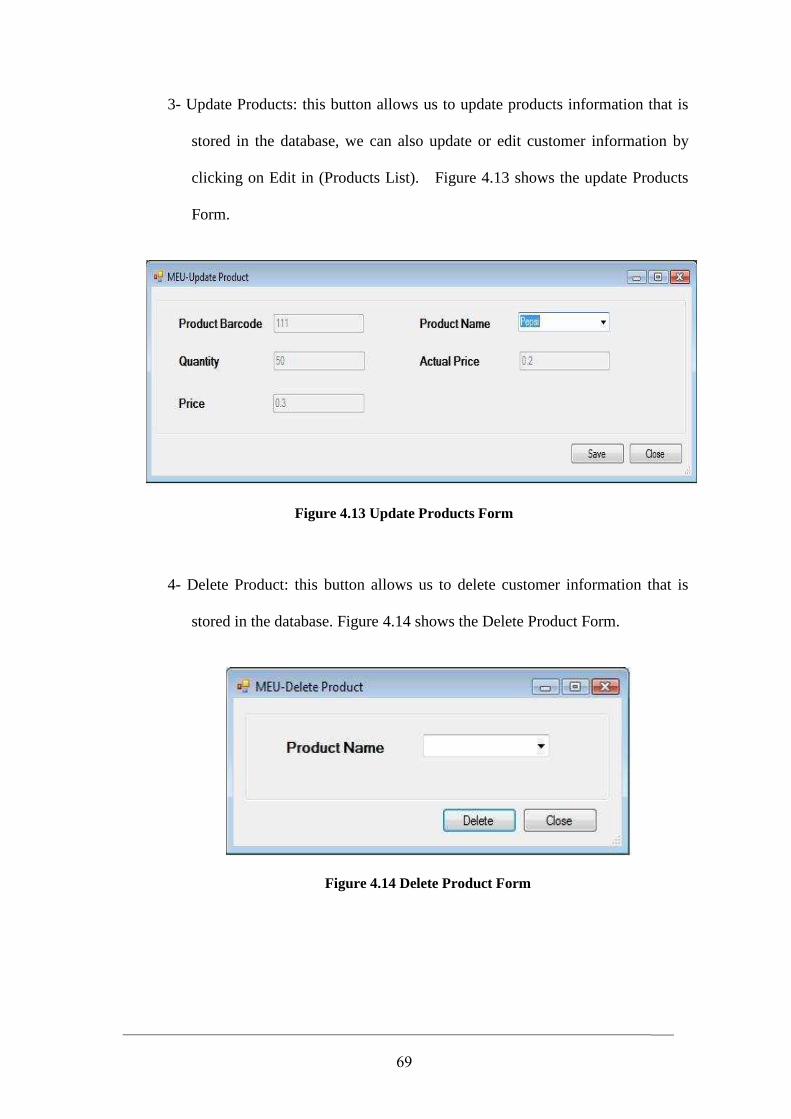
69
3- Update Products: this button allows us to update products information that is
stored in the database, we can also update or edit customer information by
clicking on Edit in (Products List). Figure 4.13 shows the update Products
Form.
Figure 4.13 Update Products Form
4- Delete Product: this button allows us to delete customer information that is
stored in the database. Figure 4.14 shows the Delete Product Form.
Figure 4.14 Delete Product Form
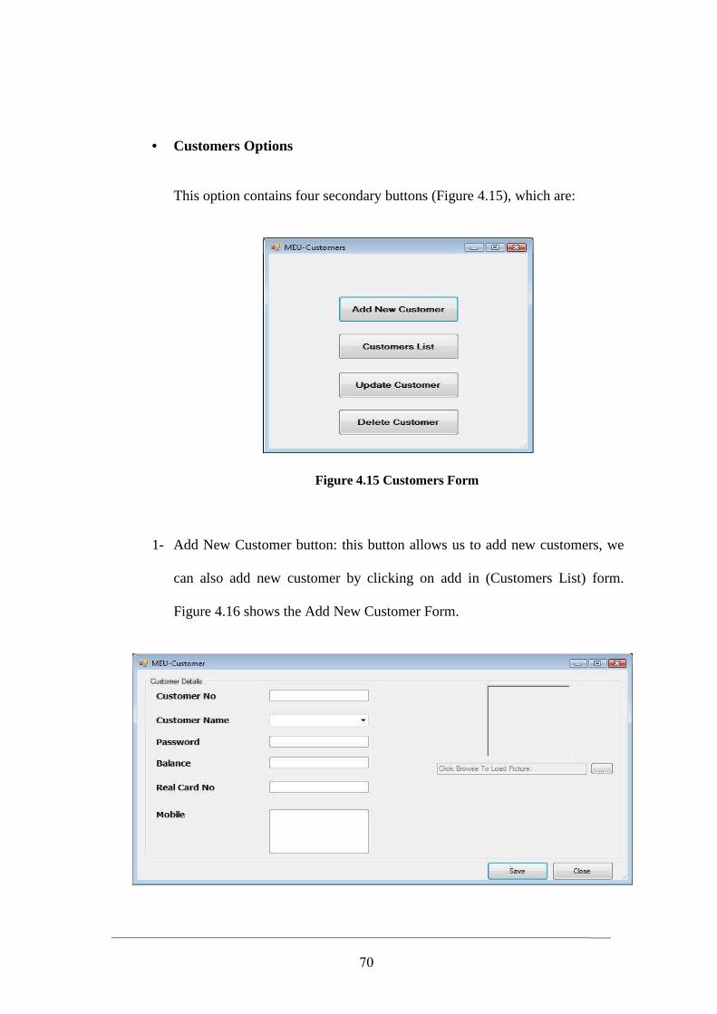
70
• Customers Options
This option contains four secondary buttons (Figure 4.15), which are:
Figure 4.15 Customers Form
1- Add New Customer button: this button allows us to add new customers, we
can also add new customer by clicking on add in (Customers List) form.
Figure 4.16 shows the Add New Customer Form.
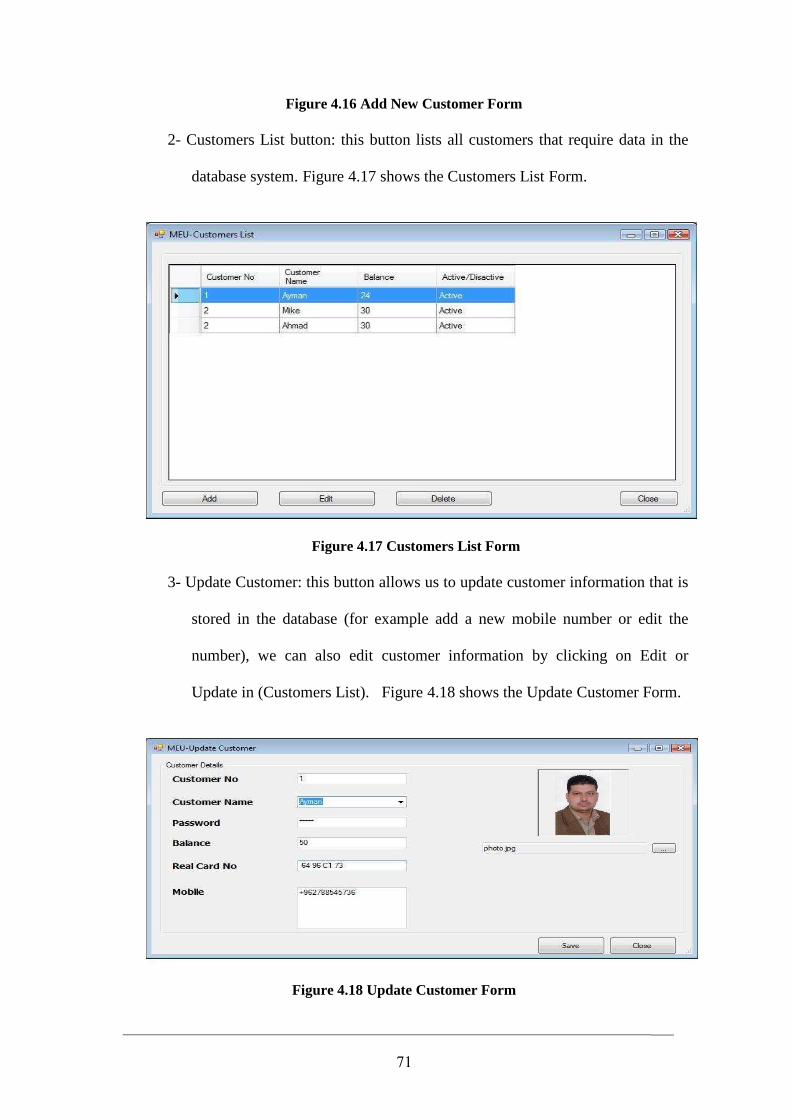
71
Figure 4.16 Add New Customer Form
2- Customers List button: this button lists all customers that require data in the
database system. Figure 4.17 shows the Customers List Form.
Figure 4.17 Customers List Form
3- Update Customer: this button allows us to update customer information that is
stored in the database (for example add a new mobile number or edit the
number), we can also edit customer information by clicking on Edit or
Update in (Customers List). Figure 4.18 shows the Update Customer Form.
Figure 4.18 Update Customer Form
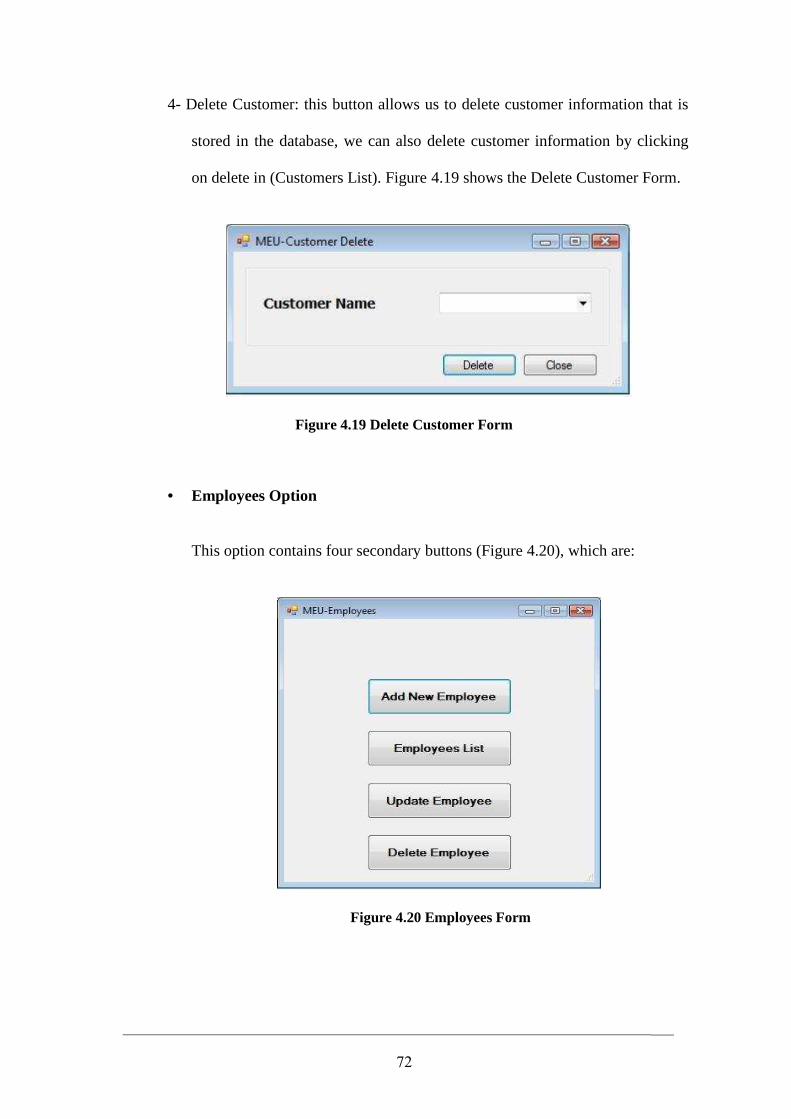
72
4- Delete Customer: this button allows us to delete customer information that is
stored in the database, we can also delete customer information by clicking
on delete in (Customers List). Figure 4.19 shows the Delete Customer Form.
Figure 4.19 Delete Customer Form
• Employees Option
This option contains four secondary buttons (Figure 4.20), which are:
Figure 4.20 Employees Form
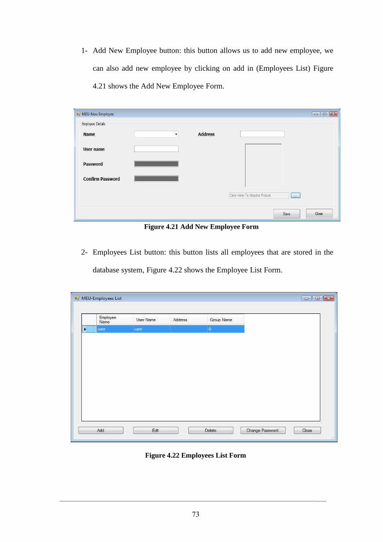
73
1- Add New Employee button: this button allows us to add new employee, we
can also add new employee by clicking on add in (Employees List) Figure
4.21 shows the Add New Employee Form.
Figure 4.21 Add New Employee Form
2- Employees List button: this button lists all employees that are stored in the
database system, Figure 4.22 shows the Employee List Form.
Figure 4.22 Employees List Form
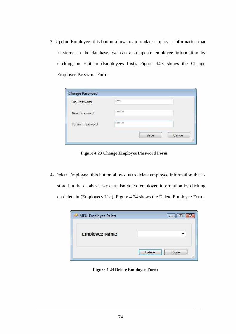
74
3- Update Employee: this button allows us to update employee information that
is stored in the database, we can also update employee information by
clicking on Edit in (Employees List). Figure 4.23 shows the Change
Employee Password Form.
Figure 4.23 Change Employee Password Form
4- Delete Employee: this button allows us to delete employee information that is
stored in the database, we can also delete employee information by clicking
on delete in (Employees List). Figure 4.24 shows the Delete Employee Form.
Figure 4.24 Delete Employee Form
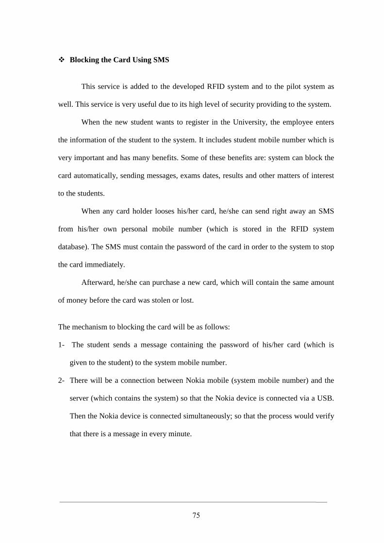
75
� Blocking the Card Using SMS
This service is added to the developed RFID system and to the pilot system as
well. This service is very useful due to its high level of security providing to the system.
When the new student wants to register in the University, the employee enters
the information of the student to the system. It includes student mobile number which is
very important and has many benefits. Some of these benefits are: system can block the
card automatically, sending messages, exams dates, results and other matters of interest
to the students.
When any card holder looses his/her card, he/she can send right away an SMS
from his/her own personal mobile number (which is stored in the RFID system
database). The SMS must contain the password of the card in order to the system to stop
the card immediately.
Afterward, he/she can purchase a new card, which will contain the same amount
of money before the card was stolen or lost.
The mechanism to blocking the card will be as follows: 1- The student sends a message containing the password of his/her card (which is
given to the student) to the system mobile number.
2- There will be a connection between Nokia mobile (system mobile number) and the
server (which contains the system) so that the Nokia device is connected via a USB.
Then the Nokia device is connected simultaneously; so that the process would verify
that there is a message in every minute.
76
3- When any message comes to the system, the system analyzes the message and saves
the card number and password's card, so the card number and password as inputs to
the system and the output action is to block the student's card who sent the message
4- Within the system, the program receives input from mobile, the program will search
in the database through an specific algorithm and matching card number with
student’s number that is stored in the database, if the card number and the password
is the same as the sent password, then the program blocks the card, so anyone
cannot use this card again.
5- Then the software deletes the message automatically, and will be ready to accept any
other message.
This thesis use the PC connectivity to connect the mobile with the PC. PC
connectivity enables synchronizing of a user's personal information data, such as
contacts and calendar entries, installing applications, performing backup and restore, and
transferring data (images, video, music, etc.) between the user's mobile device and a PC
using short-range protocols such as Bluetooth, infrared, serial port, and USB.
The PC Suite API is available for application developers and ISVs. The API is
an integrated part of the Nokia PC Suite and it takes advantage of the suite's existing
capabilities. It has been designed to free the user from the complexity of the connectivity
and transmission protocols and mobile phone system architecture, thus enables faster PC
connectivity application development.
Figure 4.25, shows the flowchart of blocking the card using SMS in thesis
developed system.
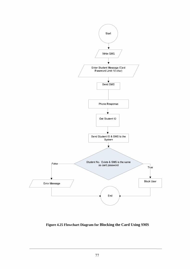
77
Figure 4.25 Flowchart Diagram for Blocking the Card Using SMS
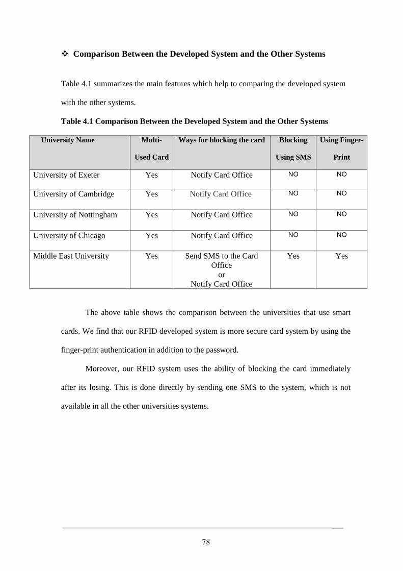
78
� Comparison Between the Developed System and the Other Systems
Table 4.1 summarizes the main features which help to comparing the developed system
with the other systems.
Table 4.1 Comparison Between the Developed System and the Other Systems
Name University Multi-
Used Card
Ways for blocking the card Blocking
Using SMS
Using Finger-
University of Exeter Yes Notify Card Office NO NO
University of Cambridge Yes Notify Card Office NO NO
University of Nottingham Yes Notify Card Office NO NO
University of Chicago Yes Notify Card Office NO NO
Middle East University Yes Send SMS to the Card Office
or Notify Card Office
Yes Yes
The above table shows the comparison between the universities that use smart
cards. We find that our RFID developed system is more secure card system by using the
finger-print authentication in addition to the password.
Moreover, our RFID system uses the ability of blocking the card immediately
after its losing. This is done directly by sending one SMS to the system, which is not
available in all the other universities systems.
79
Chapter 5
Conclusions and Future Work
5.1 Conclusions
In this section, we summarize the conclusions of our thesis, these are:
1- The developed system using the contactless cards in MEU and this system is a
universal cost-effective identification solution addressing a wide range of
applications in the university.
2- The anti-collision capability in the developed system and its ability to be read or
written without a slot, a direct line of sight (like contact credit cards) make this
technology more efficient in comparison with currently used systems.
3- Since no item can pass by a transponder reader without being scanned and/or
updated, human intervention and its associated costs are significantly reduced.
4- Using smartcards developed system in MEU ‘stored value cards’ reduce the
instances in which physical cash is used in making payments.
5- The developed system contains improvements in security techniques. These
improvements will success tackling the problems of fraud, and give greater
confidence in such systems.
80
5.2 Future Work
In order to extend the system that is developed in this thesis, we suggest several
recommendations for future work, these are:
1- Making the contactless card the only card you will carry in your wallet at the
university (All money transactions are made by the card).
2- Adding more security through enhancing the point of sales, by adding a finger
print authentication device to recognize the user, and validate encryption of
database by using special software.
3- For every student, an SMS could be used (of the same mobile number stored in
the student database) to contact the student whenever is needed and to inform the
student of any new action in the University.
For example, when the student finishes his registration, he/she will
receive an SMS to confirm his precise date of starting the course, to inform him
about his/ her results for every subject, and to inform him about the due date of
returning the books he had borrowed from the library.
4- This card system provides a highly secure level; it will decrease the use of the
security staff in the entrance of the University and will monitor the coming and
leaving of everyone, in addition to that this card system contain the event viewer
software, this event viewer software will enable us to monitor any student and
employee’s exact date and time of any action taken by everyone in the
University.
81
References
Al-Mousawi, Hussain 2004,’ Performance and Reliability of Radio Frequency
Identification(RFID)’ Master Thesis, Agder University College, Norway Available
at:<http://student.grm.hia.no/master/ikt04/ikt6400/g28/Document/Master_Thesis.pdf>
[Viewed 05 April 2010]
A Smart Card Alliance Contactless Payments Council 2006, ’The What, Who and Why
of Contactless Payments’, CPC-06002, Smart Card Alliance , Available at:
< http://www.smartcardalliance.org/resources/pdf/CP_What_Who_Why_Final.pdf >
[Viewed 12 April 2010]
Bill, Glover & Himanshu, Bhatt 2006, RFID Essentials, 1st edn, O'Reilly Media, Inc.
USA. Cambridge University (2003), University Cambridge Smart Card [online].
Available at: < http://www.admin.cam.ac.uk/offices/misd/univcard/ > [Viewed 3
March 2010]
Carmelo, R. García, Ricardo, Pérez, Joaquín, Caraballo, Francisco, Alayón & Gabino,
Padrón 2005, ‘A Proposal for a Payment System for Public Transport Based on the
Ubiquitous Paradigm’ Available at: < http://sunsite.informatik.rwth-
aachen.de/Publications/CEUR-WS/Vol-208/paper30.pdf > [Viewed 12 April 2010]
Carolyn, S. 2006 ‘If You Really Hate to Wait’, San Francisco Chronicle 17 Feb. 2006.
Available at:<http://www.sfgate.com/cgi- bin/ article.cgi?file= /c/a/2006/02/17/
CONTACTLESS.TMP&nl=top > [Viewed 10 April 2010]
Casset L., Lanet J. L. (2002). Increasing Smart Card Dependability. ACM SIGOPS
European workshop [online], Available at:
< http://citeseerx.ist.psu.edu/viewdoc/summary?doi=10.1.1.10.1795 > [Viewed 27
March 2010]
Chicago University (2008). Identifications Smart Card [online]. Available at:
< http://nsit.uchicago.edu/services/chicagocard/ > [Viewed 12 April 2010]
82
Chris, Cook, Konstantin, Aslanidis & Helfried, Vollbrecht 2007, ‘Improving
Consumers’ Contactless Payment Experience’ Texas Instruments, Inc. Available at:
<http://www.ti.com/rfid/docs/manuals/whtPapers/wp-improving_payment_experience
.pdf > [Viewed 12 April 2010]
Dennis, Brown 2007, RFID Implementation, McGraw-Hill Companies, USA.
Dhem Jean-Francois and Nathalie Feyt,. IEEE Micro, Vol:21, issue:6, Nov 2001, p.14-25.
Jean-Francois and Nathalie Feyt, Hardware and Software Symbiosis Helps Smart Card
Evolution.IEEE Micro, Vol:21, issue:6, Nov-Dec 2001,p.14-25. Available at: <http://
portal.acm.org/citation.cfm?id=359340.359342&coll=portal&dl=ACM&idx=35>[12April
2010]
Exeter University (2008). Smart Card [online]. Available at:
< http://as.exeter.ac.uk/support/admin/taught/unicard/> [Viewed 12 April 2010]
Finkenzeller, Klaus 2004, RFID Handbook Fundamentals and applications in
Contactless Smart Cards and Identification, 2nd edn, Carl Hanser Verlag, Munich/FRG.
Germany.
Jerry, Banks, David, Hanny, Manuel, A. Pachano & Les ,G. Thompson 2007, RFID
Applied, John Wiley and Sons, USA.
Handschuh, H 2004, ‘Contactless Technology Security Issues’, Information security
Bulletin 9, Information security Bulletin, Gemplus, p.95 Available at:< http://www. chi-
publishing. com/samples/ISB0903HH.pdf > [Viewed 12 April 2010]
International Organization for Standardization 2005, Available at:
< http://www.iso.org/iso/home.htm > [02 MArch 2010]
Isao Shirakawa, 2008, art of RFID Tags and Their Applications Market research, 2006, Conference Documentation: Contactless Cards, Available at:
< http://www.marketresearch.com/product/display.asp >[10 February 2010]
83
Nottingham University (2008). Smart Card [online]. Available at:
< http://www.nottingham.ac.uk/smartcard/> [Viewed 12 April 2010]
NXP 2006, NXP Semiconductor,, Available at: < www.semiconductors.philips.com >
[Viewed 12 April 2010]
Ottawa University (2008). University of Ottawa Implements Smart Card [online].
Available at: < http://www.secureidnews.com/news/2002/01/14/university-of-
ottawaimplements-smart-card/> [Viewed 12 April 2010]
Pete, Sorrells 2002, Passive RFID Basics, AN680, Microchip Technology Inc.,
Available at:<http://www.microchip.com/stellent/idcplg?IdcService=SS_GET_PAGE&
nodeId =1824&appnote=en011768 > [Viewed 12 April 2010]
Philips 2008, Philips Datasheet, Available at:
< http://www.datasheetcatalog.com/philips/1/ > [Viewed 12 April 2010]
Srinivasa, S, Rajan, G & Lalkishore, K 2009 ‘Human Activity Tracking Using RFID
Tags’, IJCSNS International Journal of Computer Science and Network Security,
VOL.9, No.1 , January 2009 Available at:
< http://paper.ijcsns.org/07_book/200901/20090154.pdf > [Viewed 12 April 2010]
Technovelgy 2005, Contactless Smart Card, Available at: < http://www.technovelgy.
com /ct/Technology-Article.asp?ArtNum=27 > [Viewed 12 April 2010]
Technovelgy 2005, Contactless Credit Card Advantages, Available at:
< http://www.technovelgy.com/ct/Technology-Article.asp?ArtNum=62 > [Viewed 12
April 2010]
Wikipedia , Available at: < http://en.wikipedia.org/wiki/Data_flow_diagram> [Viewed
10 April 2010]
Wolfgang, Rankl & Wolfgang, Effing 2003, Smart Card Handbook , 3rd edn, Carl
Hanser Verlag, Munich/FRG. Germany.
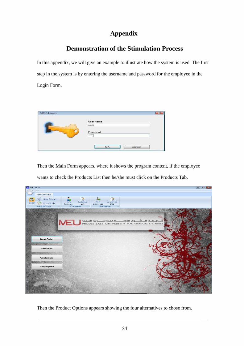
84
Appendix
Demonstration of the Stimulation Process
In this appendix, we will give an example to illustrate how the system is used. The first
step in the system is by entering the username and password for the employee in the
Login Form.
Then the Main Form appears, where it shows the program content, if the employee
wants to check the Products List then he/she must click on the Products Tab.
Then the Product Options appears showing the four alternatives to chose from.
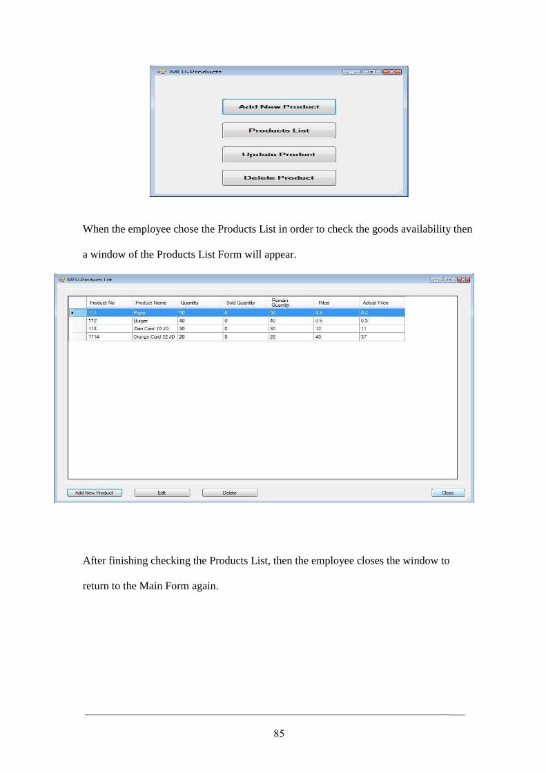
85
When the employee chose the Products List in order to check the goods availability then
a window of the Products List Form will appear.
After finishing checking the Products List, then the employee closes the window to
return to the Main Form again.
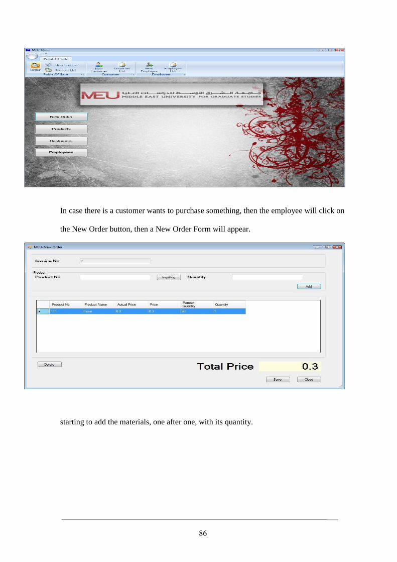
86
In case there is a customer wants to purchase something, then the employee will click on
the New Order button, then a New Order Form will appear.
starting to add the materials, one after one, with its quantity.
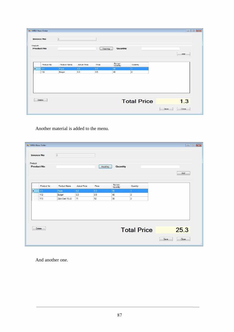
87
Another material is added to the menu.
And another one.
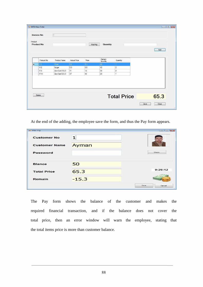
88
At the end of the adding, the employee save the form, and thus the Pay form appears.
The Pay form shows the balance of the customer and makes the
required financial transaction, and if the balance does not cover the
total price, then an error window will warn the employee, stating that
the total items price is more than customer balance.
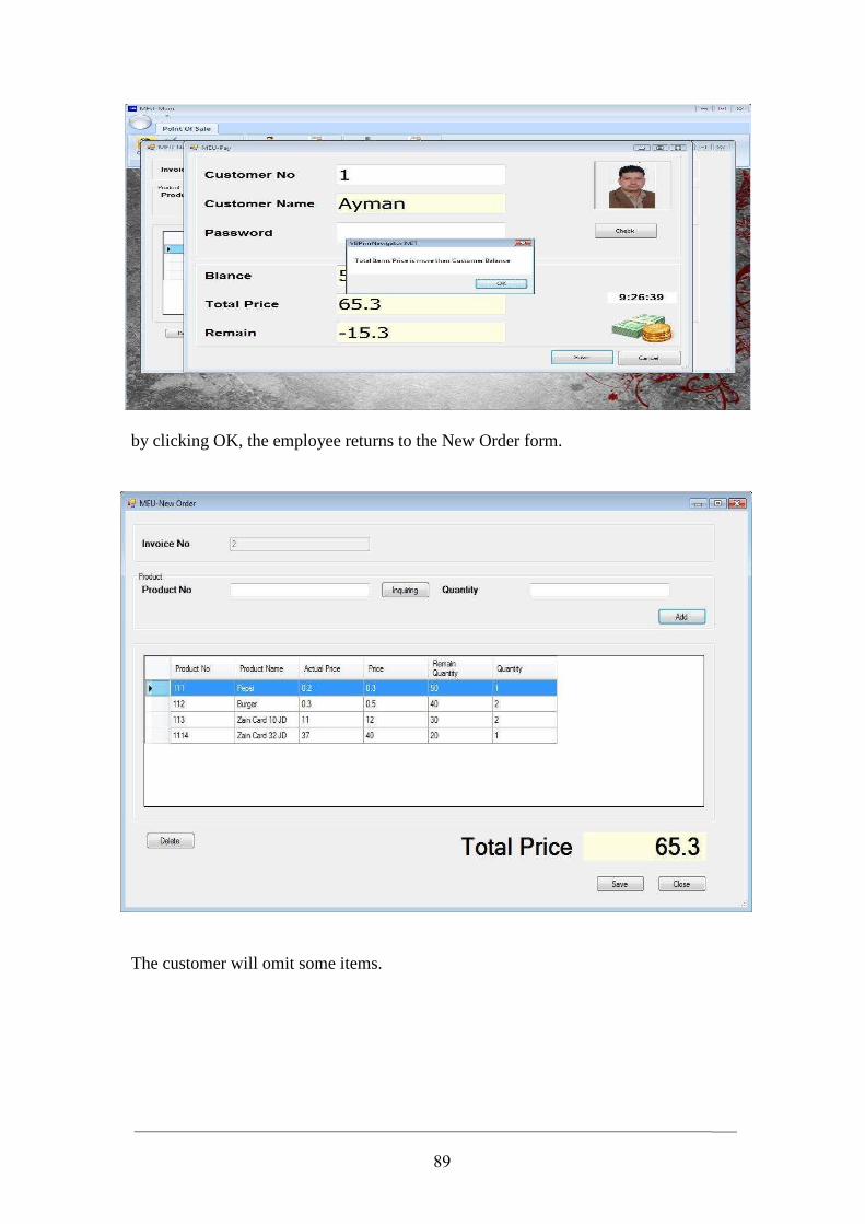
89
by clicking OK, the employee returns to the New Order form.
The customer will omit some items.
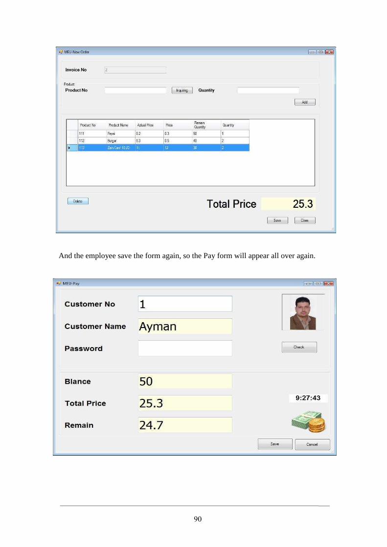
90
And the employee save the form again, so the Pay form will appear all over again.
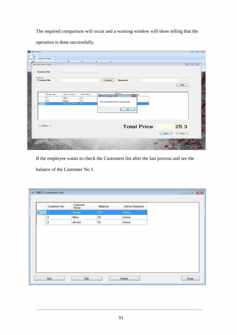
91
The required comparison will occur and a warning window will show telling that the
operation is done successfully.
If the employee wants to check the Customers list after the last process and see the
balance of the Customer No 1.
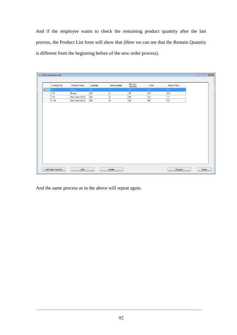
92
And if the employee wants to check the remaining product quantity after the last
process, the Product List form will show that (Here we can see that the Remain Quantity
is different from the beginning before of the new order process).
And the same process as in the above will repeat again.
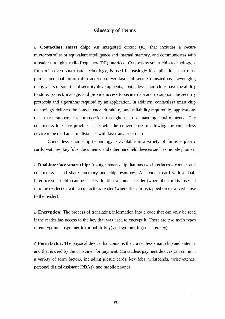
93
Glossary of Terms ⌂ Contactless smart chip: An integrated circuit (IC) that includes a secure
microcontroller or equivalent intelligence and internal memory, and communicates with
a reader through a radio frequency (RF) interface. Contactless smart chip technology, a
form of proven smart card technology, is used increasingly in applications that must
protect personal information and/or deliver fast and secure transactions. Leveraging
many years of smart card security developments, contactless smart chips have the ability
to store, protect, manage, and provide access to secure data and to support the security
protocols and algorithms required by an application. In addition, contactless smart chip
technology delivers the convenience, durability, and reliability required by applications
that must support fast transaction throughout in demanding environments. The
contactless interface provides users with the convenience of allowing the contactless
device to be read at short distances with fast transfer of data.
Contactless smart chip technology is available in a variety of forms – plastic
cards, watches, key fobs, documents, and other handheld devices such as mobile phones.
⌂ Dual-interface smart chip: A single smart chip that has two interfaces – contact and
contactless – and shares memory and chip resources. A payment card with a dual-
interface smart chip can be used with either a contact reader (where the card is inserted
into the reader) or with a contactless reader (where the card is tapped on or waved close
to the reader).
⌂ Encryption: The process of translating information into a code that can only be read
if the reader has access to the key that was used to encrypt it. There are two main types
of encryption – asymmetric (or public key) and symmetric (or secret key).
⌂ Form factor: The physical device that contains the contactless smart chip and antenna
and that is used by the consumer for payment. Contactless payment devices can come in
a variety of form factors, including plastic cards, key fobs, wristbands, wristwatches,
personal digital assistant (PDAs), and mobile phones.
94
⌂ ISO/IEC 14443: The international standard for contactless smart chips and cards that
operate (i.e., can be read from or written to) at a distance of less than 10 centimeters (4
inches). American Express, Master Card, and Visa contactless payment devices are
based on this standard.
⌂ Microcontroller: A highly integrated computer chip that contains all the components
comprising a controller. Typically, this includes a central processing unit (CPU), random
access memory (RAM), some form of read-only memory (ROM), input/output ports,
and timers. Unlike a general purpose computer, a microcontroller is designed to operate
in a restricted environment.
⌂ Near Field Communication (NFC): A short-range wireless standard (ISO/IEC
18092) that uses magnetic field induction to enable communication between devices
when they are brought close together (within 10-20 centimeters or 4-8 inches). NFC
technology is compatible with ISO/IEC 14443-based technology.
⌂ Range: The distance from which a contactless payment device can be read. American
Express, MasterCard and Visa contactless payment devices are designed to comply with
the international standard, ISO/IEC 14443, that restricts the device range to less than 4
inches (10 centimeters).
⌂ Reader: The electronic device that connects to, provides power to and communicates
with a contact or contactless smart card. Contactless readers generate in electromagnetic
field. When a contactless device is brought into the reader’s electromagnetic field, the
contactless smart chip is powered on, a wireless communication protocol is established
between the card and reader, and data can then be exchanged. For contactless payments,
contactless readers used at merchant locations integrate with point-of-sale terminals and
comply with the ISO/IEC 14443 international standard.
⌂ Radio frequency (RF): Any frequency within the electromagnetic spectrum
associated with radio wave propagation. Many wireless communications technologies
are based on RF, including radio, television, mobile phones, wireless networks and
contactless payment cards and devices.
95
⌂ Radio Frequency Identification (RFID) Tag: Simple, low-cost and disposable
electronic devices that are used to identify animals, track goods logistically and replace
printed bar codes at retailers. RFID tags include an integrated circuit that typically stores
a static number (an ID) and an antenna that enables the chip to transmit the stored
number to a reader. When the tag comes within the range of the appropriate RF reader,
the tag is powered by the reader’s RF field and transmits its ID to the reader. There is
little to know security on the RFID tag or during communication with the reader.
Typical RFID tags can be easily read from distances of several inches (centimeters) to
several yards (meters) to allow easy tracking of goods.
⌂ Smart card: A device that includes an embedded integrated circuit that can be either a
secure microcontroller or equivalent intelligence with internal memory or a memory
chip alone. The card connects to a reader with direct physical contact or with a remote
contactless RF interface. With an embedded microcontroller, smart cards have the
unique ability to store large amounts of data, carry out their own on-card functions (e.g.,
encryption and digital signatures) and interact intelligently with a smart card reader.
Smart cards are available in a variety of form factors, including plastic cards, Subscriber
Identification Modules (SIMs) used in GSM mobile phones, and USB-based tokens.
⌂ Transponder: A wireless communications device that detects and responds to an RF
signal.