Embed Size (px)
Citation preview
California State University, San Bernardino California State University, San Bernardino
CSUSB ScholarWorks CSUSB ScholarWorks
Electronic Theses, Projects, and Dissertations Office of Graduate Studies
6-2019
DEVELOPING A LOW COST BIOLOGICAL ADDITIVE DEVELOPING A LOW COST BIOLOGICAL ADDITIVE
MANUFACTURING SYSTEM FOR FABRICATING GEL EMBEDDED MANUFACTURING SYSTEM FOR FABRICATING GEL EMBEDDED
CELLULAR CONSTRUCTS. CELLULAR CONSTRUCTS.
Justin Stewart Minck California State University – San Bernardino
Follow this and additional works at: https://scholarworks.lib.csusb.edu/etd
Part of the Biotechnology Commons
Recommended Citation Recommended Citation Minck, Justin Stewart, "DEVELOPING A LOW COST BIOLOGICAL ADDITIVE MANUFACTURING SYSTEM FOR FABRICATING GEL EMBEDDED CELLULAR CONSTRUCTS." (2019). Electronic Theses, Projects, and Dissertations. 844. https://scholarworks.lib.csusb.edu/etd/844
This Thesis is brought to you for free and open access by the Office of Graduate Studies at CSUSB ScholarWorks. It has been accepted for inclusion in Electronic Theses, Projects, and Dissertations by an authorized administrator of CSUSB ScholarWorks. For more information, please contact [email protected].
DEVELOPING A LOW COST BIOLOGICAL ADDITIVE MANUFACTURING
SYSTEM FOR FABRICATING GEL EMBEDDED CELLULAR CONSTRUCTS
A Thesis
Presented to the
Faculty of
California State University,
San Bernardino
In Partial Fulfillment
of the Requirements for the Degree
Master of Science
in
Biology
by
Justin Stewart Minck
June 2019
DEVELOPING A LOW COST BIOLOGICAL ADDITIVE MANUFACTURING
SYSTEM FOR FABRICATING GEL EMBEDDED CELLULAR CONSTRUCTS
A Thesis
Presented to the
Faculty of
California State University,
San Bernardino
by
Justin Stewart Minck
June 2019
Approved by:
Dr. Nicole Bournias-Vardiabasis, Committee Chair, Biology
Dr. Michael Chao, Committee Member
Dr. Jeffrey Thompson, Committee Member

© 2019 Justin Stewart Minck
iii
ABSTRACT
Organ transplantation has made great progress since the first successful
kidney transplant in 1953 and now more than one million tissue transplants are
performed in the United States every year (www.organdonor.gov/statistics-
stories, 2015). However, the hope and success of organ transplants are often
overshadowed by their reputation as being notoriously difficult to procure
because of donor-recipient matching and availability. In addition, those that are
fortunate enough to receive a transplant are burdened with a lifetime of
immunosuppressants. The field of regenerative medicine is currently making
exceptional progress toward making it possible for a patient to be their own
donor. Cells from a patient can be collected, reprogrammed into stem cells, and
then differentiated into specific cell types. This technology combined with recent
advances in 3D printing provides a unique opportunity. Cells can now be
accurately deposited with computerized precision allowing tissue engineering
from the inside out (Gill, 2016). However, more work needs to be done as these
techniques have yet to be perfected. Bioprinters can cost hundreds of thousands
of dollars, and the bioink they consume costs thousands per liter. The resulting
cost in development of protocols required for effective tissue printing can thus be
cost-prohibitive, limiting the research to labs which can afford this exorbitant cost
and in turn slowing the progress made in the eventual creation of patient derived
stem cell engineered organs.
iv
The objective of my research is to develop a simple and low-cost
introductory system for biological additive manufacturing (Otherwise known as
3D bioprinting). To create an easily accessible and cost-effective system several
design constraints were implemented. First, the system had to use mechanical
components that could be purchased “off-the-shelf” from commonly available
retailers. Second, any mechanical components involved had to be easily
sterilizable, modifiable, and compatible with open-source software. Third, any
customized components had to be fabricated using only 3D printing and basic
tools (i.e. saw, screwdriver, and wrench). Fourth, the system and any expendable
materials should be financially available to underfunded school labs, in addition
to being sterilizable, biocompatible, customizable, and biodegradable. Finally, all
hardware and expendables had to be simple enough as to be operated by high
school science students.

v
ACKNOWLEDGEMENTS
I would like to thank my mentor, Dr. Nicole Bournias-Vardiabasis, who has
always offered me opportunities and support not only in research but in life.
Teresa Ubina and Mike Kowalski for their technical assistance, support, project
feedback and their friendship. Lastly, I would like to thank my grandparents for
their support, pushing me and encouraging in me a love of science and
engineering. Helping to raise me and being patient with me every step of the way
in all my life’s endeavors.
v
TABLE OF CONTENTS
ABSTRACT .......................................................................................................... iii
ACKNOWLEDGEMENTS ..................................................................................... v
LIST OF TABLES ............................................................................................. viiiii
LIST OF FIGURES ............................................................................................. viii
CHAPTER ONE: THE NEED FOR 3D PRINTED TISSUES
Tissue Transplant ...................................................................................... 1
Cell Culture: Then and Now ....................................................................... 2
Additive Manufacturing (3D Printing) ......................................................... 3
3D Bioprinting ............................................................................................ 5
CHAPTER TWO: MATERIALS AND METHODS
3D Printer Modification............................................................................... 8
Development of 3D Printable Syringe Pump Printhead ........................... 10
The PSP2 ................................................................................................ 12
The PSP3 ................................................................................................ 16
Initial Testing of PSP2 and PSP3 ............................................................ 19
Gelatin Bioink Development ..................................................................... 21
Syringe Loading and Tip Optimization ..................................................... 26
CHAPTER THREE: PROJECT DATA
Optimization Data .................................................................................... 30
Final Project Data .................................................................................... 35
CHAPTER FOUR: DISCUSSION AND FUTURE WORK
Discussion ............................................................................................... 42

vi
Future Work ............................................................................................. 43
APPENDIX A: AVERAGE CELL COUNT DATA GRAPHS ................................ 45
APPENDIX B: IMAGEXPRESS AND IMAGEJ DATA ......................................... 49
REFERENCES ................................................................................................... 53

vii
LIST OF TABLES
Table 1. Bovine Based Bioink Concentration Optimization ................................. 22
Table 2. Syringe Tip and MTGase Concentration Optimization .......................... 32
viii
LIST OF FIGURES
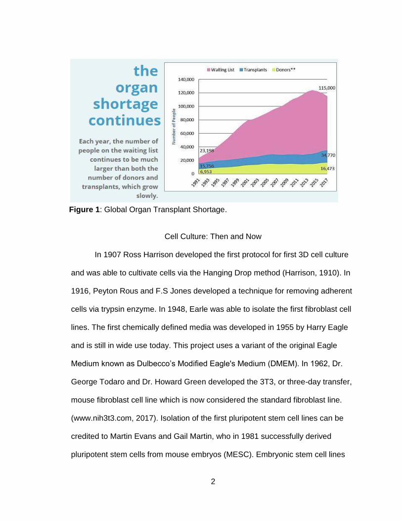
Figure 1. Global Organ Transplant Shortage. ...................................................... 2
Figure 2. NovoGen MMX. .................................................................................... 5
Figure 3. SE3D Rebel Mini. ................................................................................. 6
Figure 4. Creator Pro 3D Printer. ....................................................................... 10
Figure 5. Printed Syringe Pump. ........................................................................ 11
Figure 6. Flashprint Software Adjustments. ....................................................... 12
Figure 7. Printed Syringe Pump 2. ..................................................................... 13
Figure 8. PSP1, PSP2, PSP2-A, PSP2-B. ......................................................... 15
Figure 9. Printed Syringe Pump 3. ..................................................................... 17
Figure 10. Human Ear Construct. ...................................................................... 20
Figure 11. Bovine gelatin type B bioink. ............................................................ 22
Figure 12. Gram Positive Bacilli Bacterial Contamination. ................................. 23
Figure 13. 3T3 Cells Cultured in Bioink. ............................................................ 25
Figure 14. 5mL Disposable Syringes. ................................................................ 27
Figure 15. Bioink Sterilization Optimization. ...................................................... 30
Figure 16. 3T3 Cells in Bioink. ........................................................................... 31
Figure 17. GFP 3T3 Cells in Optimized Bioink. ................................................. 33
Figure 18. Bioink Processing Procedure. .......................................................... 34
Figure 19. ImageXpress Z-Stack Well Locations Diagram. ............................... 36
Figure 20. ImageJ Z-Stack Cell Counting Macro. .............................................. 37
Figure 21. Average Cell Differential Count Experiment Vs Control. ................... 39
ix
Figure 22. Average Cell Differential Count Experiment Vs Control. ................... 39
Figure 23. Average Middle Cell Differential Count Experiment Vs Control. ....... 40
Figure 24. Average Top Cell Differential Count Experiment Vs Control. ........... 40
1
CHAPTER ONE
THE NEED FOR 3D PRINTED TISSUES
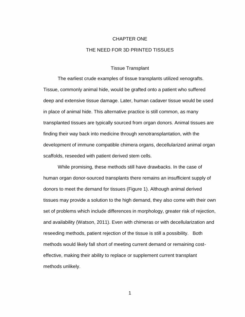
Tissue Transplant
The earliest crude examples of tissue transplants utilized xenografts.
Tissue, commonly animal hide, would be grafted onto a patient who suffered
deep and extensive tissue damage. Later, human cadaver tissue would be used
in place of animal hide. This alternative practice is still common, as many
transplanted tissues are typically sourced from organ donors. Animal tissues are
finding their way back into medicine through xenotransplantation, with the
development of immune compatible chimera organs, decellularized animal organ
scaffolds, reseeded with patient derived stem cells.
While promising, these methods still have drawbacks. In the case of
human organ donor-sourced transplants there remains an insufficient supply of
donors to meet the demand for tissues (Figure 1). Although animal derived
tissues may provide a solution to the high demand, they also come with their own
set of problems which include differences in morphology, greater risk of rejection,
and availability (Watson, 2011). Even with chimeras or with decellularization and
reseeding methods, patient rejection of the tissue is still a possibility. Both
methods would likely fall short of meeting current demand or remaining cost-
effective, making their ability to replace or supplement current transplant
methods unlikely.
2
Cell Culture: Then and Now
In 1907 Ross Harrison developed the first protocol for first 3D cell culture
and was able to cultivate cells via the Hanging Drop method (Harrison, 1910). In
1916, Peyton Rous and F.S Jones developed a technique for removing adherent
cells via trypsin enzyme. In 1948, Earle was able to isolate the first fibroblast cell
lines. The first chemically defined media was developed in 1955 by Harry Eagle
and is still in wide use today. This project uses a variant of the original Eagle
Medium known as Dulbecco’s Modified Eagle's Medium (DMEM). In 1962, Dr.
George Todaro and Dr. Howard Green developed the 3T3, or three-day transfer,
mouse fibroblast cell line which is now considered the standard fibroblast line.
(www.nih3t3.com, 2017). Isolation of the first pluripotent stem cell lines can be
credited to Martin Evans and Gail Martin, who in 1981 successfully derived
pluripotent stem cells from mouse embryos (MESC). Embryonic stem cell lines
Figure 1: Global Organ Transplant Shortage.
3
yielded many advancements in the field of medicine however were subject to
controversy ultimately research was subsequently restricted in 2001 by the Bush
administration. In 2006, Dr. Shinya Yamanaka and his team were able to induce
successful pluripotency in mouse cells, creating the first induced pluripotent stem
cells (iPSCs). The benefit of iPSCs is that they are easily obtainable terminally
differentiated cell samples which can be reprogrammed back into a stem-like
state and then differentiated toward a specific lineage. This method when
combined with 3D printing certainly has the potential in the clinical setting to
produce patient-compatible tissue constructs.
Researchers have clearly made huge advances in cell culture; There
remains two major hurdles in the clinical applications of cell culture. The first is
the difficulty of culturing large quantities of stem cells suitable for use in
treatments. Currently cell sorting and bioreactors seem to be the most promising
technologies to overcome this obstacle (Mironov, 2011). The second obstacle is
controlled differentiation. Controlled differentiation requires manipulation of the
intracellular and extracellular chemical environments over time, as well as the
mechanical microenvironments. 3D printing technology has the potential to
resolve these issues, as chemical and mechanical gradients can be introduced
into the construct’s design. This would emulate the natural environmental signals
that normally guide stem cell differentiation in vivo.
Additive Manufacturing (3D Printing)
4
The earliest roots of modern 3D printing date back to the 1950s with the
advent of inkjet printing systems. The first patent for a 3D printing system was
filed in 1984 by Charles Hull. The system used a vat of UV sensitive
photopolymer with a Z-axis platform; a UV laser activates a photo initiator that in
turn crosslinks molecules in polystyrene resin. This occurs layer-by-layer as the
Z-axis platform submerges into the vat (www.3dsystems.com/our-story, 2017).
The systems were expensive, unreliable, and time-consuming, but could convert
a 3D computer model into a physical model overnight. The process was named
Stereolithography, or SL[A]. Charles Hull went on to launch one of the first major
manufacturers of today’s 3D printers, 3D Systems.
In 1986, Scott Crump developed a method called fused deposition
modeling (FDM), using a modified hot glue gun to extrude molten plastic
(Horvath, 2014). This system proved to be the forbearer of most 3D printers to
come. In FDM, molten plastic is extruded from a heated tip mounted to an XYZ
platform, allowing it to create 3D objects. Crump went on to launch Stratasys
Systems, the largest 3D printer manufacturer today (Savini, 2015).
In 2005, Adrian Bowyer founded the Replication Rapid Prototyper
(RepRap) project. His goal was to develop an open-source 3D printing system
capable of self-replication. Project RepRap went on to birth the modern home 3D
printing industry, as it allowed for low-cost printers to be built at home. One of its
descendants, MakerBot, has become the gold standard of affordable home 3D
printers. The RepRap project made use of Arduino modular computers and FDM
5
printing techniques to make 3D printing an affordable alternative to traditional
subtractive manufacturing. Presently, 3D printers are no longer limited to plastics
-- they can print glass, metal, sugar, clay, and even cell-infused gels for
bioprinting applications (Goldberg, 2017).
3D Bioprinting
Bioprinting is at the cutting edge
of engineering and biology. The process
combines Computer Aided Drafting
(CAD), additive manufacturing (3D
printing), and tissue culture to produce
living, three-dimensional structures. The
history of bioprinting is relatively short.
In 1999, Dr. Anthony Atala successfully
used a 3D printer to print scaffolds.
These scaffolds were seeded with living cells, creating an artificially engineered
bladder. Later in 2003, Thomas Boland developed the first method for modifying
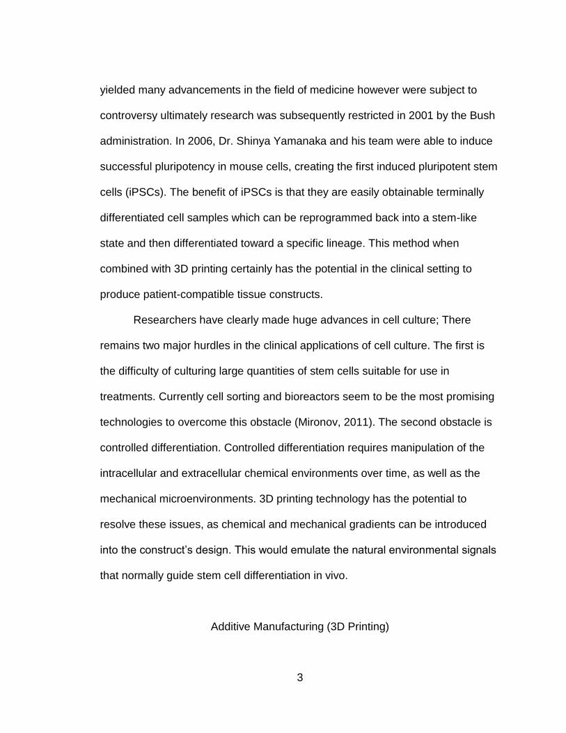
an inkjet printer for cell distribution (Murphy, 2014). In 2009, the company
Organovo began development of the NovoGen MMX Bioprinter (Figure 2), one of
the first purpose-built bioprinters. The same year, researchers at Organovo
successfully integrated vasculature into printed structures. This advancement
Figure 2: NovoGen MMX.
6
was important as media diffusion limits the thickness and size of bio printed
constructs (www.organovo.com/about/history/, 2017).
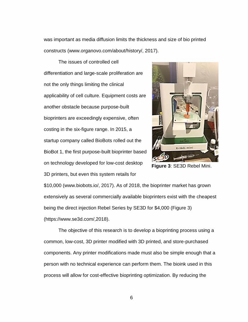
The issues of controlled cell
differentiation and large-scale proliferation are
not the only things limiting the clinical
applicability of cell culture. Equipment costs are
another obstacle because purpose-built
bioprinters are exceedingly expensive, often
costing in the six-figure range. In 2015, a
startup company called BioBots rolled out the
BioBot 1, the first purpose-built bioprinter based
on technology developed for low-cost desktop
3D printers, but even this system retails for
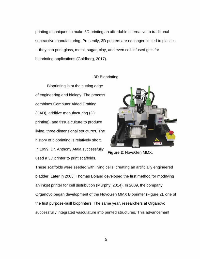
$10,000 (www.biobots.io/, 2017). As of 2018, the bioprinter market has grown
extensively as several commercially available bioprinters exist with the cheapest
being the direct injection Rebel Series by SE3D for $4,000 (Figure 3)
(https://www.se3d.com/,2018).
The objective of this research is to develop a bioprinting process using a
common, low-cost, 3D printer modified with 3D printed, and store-purchased
components. Any printer modifications made must also be simple enough that a
person with no technical experience can perform them. The bioink used in this
process will allow for cost-effective bioprinting optimization. By reducing the
Figure 3: SE3D Rebel Mini.

7
hardware, and overhead costs of this technology I hope to make it available to
Biology students at the high school and college level. Providing introductory
students meaningful STEM research experience.
8
CHAPTER TWO
MATERIALS AND METHODS
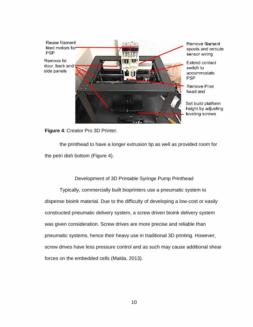
3D Printer Modification
The printer chosen for this project was the Creator Pro dual-head desktop
3D printer by FlashForge. This printer was chosen for several reasons. The
printer is one of the lowest-cost dual head printers on the market. This fulfilled
one of the primary goals of the project as the unit cost was under $1,000. The
benefit of having a dual head printer instead of a single head printer was that not
only could the printer print using two different materials simultaneously without
the need to switch syringes, but the printhead carriage and supporting XYZ drive
system was larger and more robust. A major office supply retailer carries this
product in store, thus fulfilling the goal of being easily obtainable as the machine
could be picked up locally without pre-order and added shipping costs. The
printer itself was already fully assembled out-of-the-box and is known as a
MakerBot clone. MakerBot is currently the most popular model of home desktop
3D printers. MakerBot clones can make use of some of the MakerBot legacy
software and hardware options. Overall this compatibility helps the printer meet
the third and most important goal of easy modifiability. The Creator Pro was also
chosen over lower-cost machines as it was fully enclosed with a steel frame and
has a full, removable, external enclosure -- thus making sterilization easy and the
steel frame providing more structural integrity (www.flashforge-usa.com/creator-
pro, 2017).
9
The printer is nearly fully assembled out-of-the-box, requiring only the
addition of screw-on filament spools that contain the ABS printing plastic. This
model printer also comes fully enclosed with a removable plastic shell, which
could potentially be modified to act as a sterile cabinet, although for the purposes
of this project these outer panels were removed. Removal of the outer panels
was relatively straightforward as the printer comes with the necessary wrenches
to remove any of the screws. Once the outer panels were removed, the printhead
assembly then had to be unscrewed, and the filament extrusion motors as well
as thermal sensors had to be unscrewed from the printhead assembly. The
extrusion heads, heatsinks, and cooling fans, as well as printhead chassis, were
then discarded. The thermal sensors and unneeded wiring were then detached
from the harness and conduit tube. The sensors were screwed into an unused
socket and the excess wiring was then coiled up and zip-tied under the printer
XYZ chassis. The conduit tube was then removed to help mitigate the possibility
of sterilization issues. The X-axis touch sensors were removed from their clip-on
housings and secured via hot glue to a thin 2 cm x 3 cm ABS card. This card was
then slid back into the clip effectively extending the touch sensor beyond the XYZ
chassis frame and preventing the bio printhead from contacting the chassis
frame. This modification was later reversed after the integration of an extended
contact bracket on the PSP2-B and later bio printhead variants. Lastly, the build
platform was dropped approximately 5 mm via the lowering wingnuts, which are
typically used to level the platform during initial setup. This adjustment allowed
10
the printhead to have a longer extrusion tip as well as provided room for
the petri dish bottom (Figure 4).
Development of 3D Printable Syringe Pump Printhead
Typically, commercially built bioprinters use a pneumatic system to
dispense bioink material. Due to the difficulty of developing a low-cost or easily
constructed pneumatic delivery system, a screw driven bioink delivery system
was given consideration. Screw drives are more precise and reliable than
pneumatic systems, hence their heavy use in traditional 3D printing. However,
screw drives have less pressure control and as such may cause additional shear
forces on the embedded cells (Malda, 2013).
Figure 4: Creator Pro 3D Printer.
11
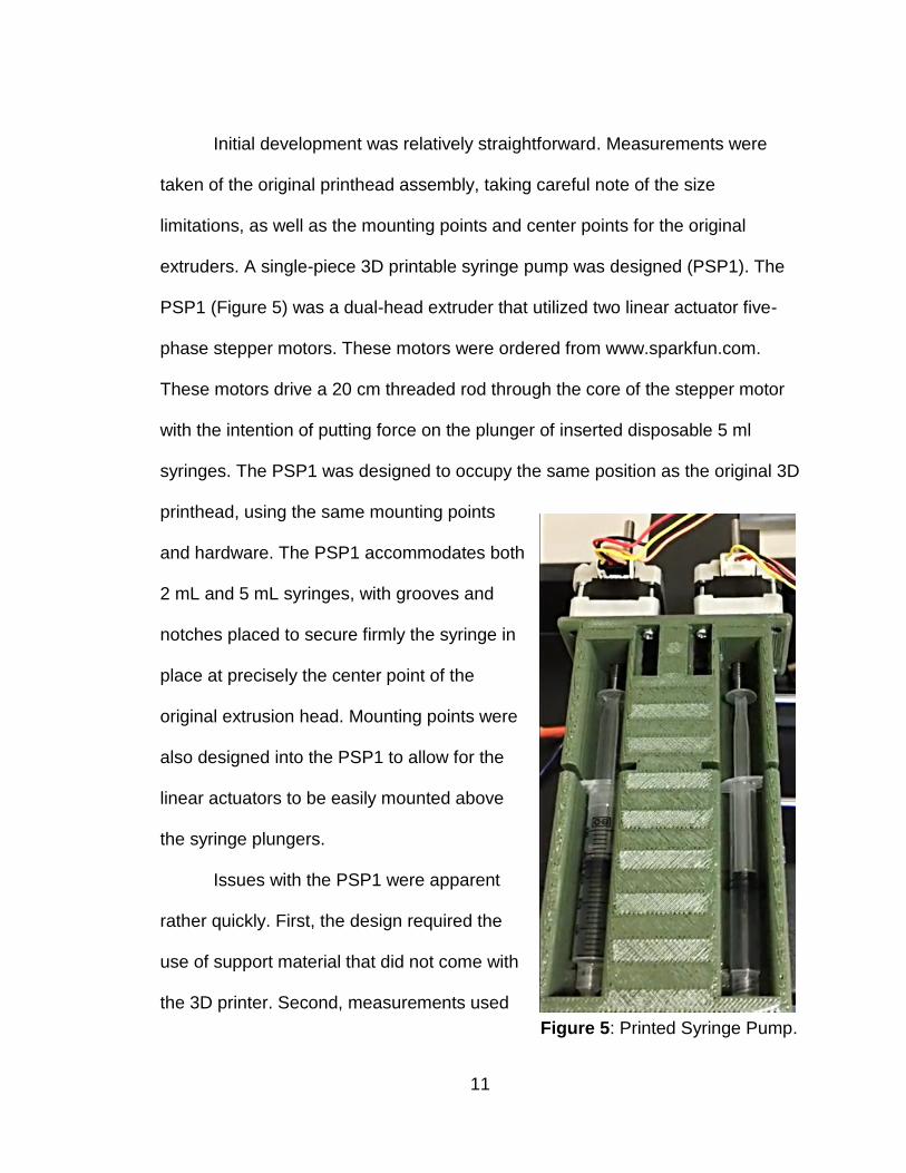
Initial development was relatively straightforward. Measurements were
taken of the original printhead assembly, taking careful note of the size
limitations, as well as the mounting points and center points for the original
extruders. A single-piece 3D printable syringe pump was designed (PSP1). The
PSP1 (Figure 5) was a dual-head extruder that utilized two linear actuator five-
phase stepper motors. These motors were ordered from www.sparkfun.com.
These motors drive a 20 cm threaded rod through the core of the stepper motor
with the intention of putting force on the plunger of inserted disposable 5 ml
syringes. The PSP1 was designed to occupy the same position as the original 3D
printhead, using the same mounting points
and hardware. The PSP1 accommodates both
2 mL and 5 mL syringes, with grooves and
notches placed to secure firmly the syringe in
place at precisely the center point of the
original extrusion head. Mounting points were
also designed into the PSP1 to allow for the
linear actuators to be easily mounted above
the syringe plungers.
Issues with the PSP1 were apparent
rather quickly. First, the design required the
use of support material that did not come with
the 3D printer. Second, measurements used
Figure 5: Printed Syringe Pump.
12
in the design did not consider a notch in the XYZ carriage, which resulted in the
syringe pump needing to be trimmed down via a rotary tool by Dremel to fit into
the carriage. Third, the force required to compress a gel-loaded syringe was
more than the linear actuator could supply. The syringe pump was also heavy
even after having been printed using a honeycomb or “low infill” setting plus a
large internal cavity. The syringe fitting was also unsatisfactory as it was difficult
to load and unload syringes without risking tip contamination.
The PSP2
The PSP2 was designed in response to these challenges. The PSP2 was
significantly reduced in material and designed with flat printing surfaces in mind,
thus removing the need for printing of support material. The PSP2 (Figure 7) also
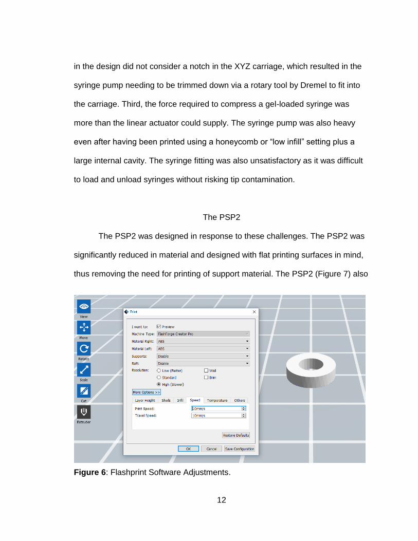
Figure 6: Flashprint Software Adjustments.
13
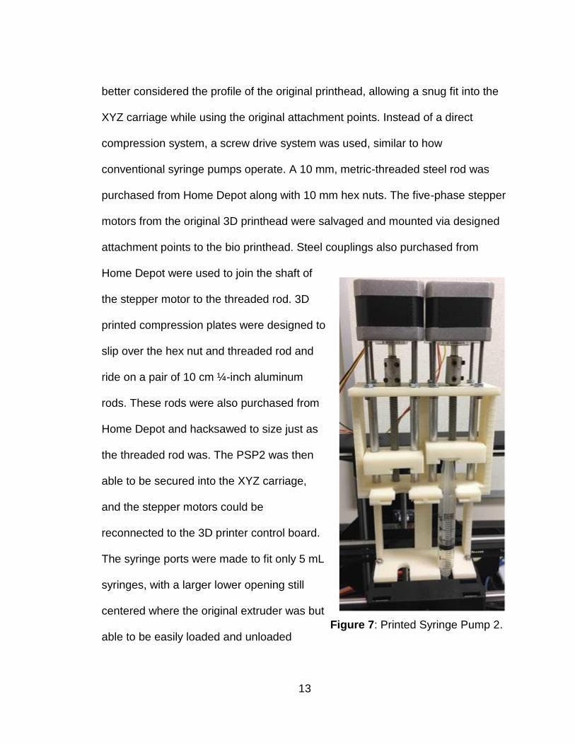
better considered the profile of the original printhead, allowing a snug fit into the
XYZ carriage while using the original attachment points. Instead of a direct
compression system, a screw drive system was used, similar to how
conventional syringe pumps operate. A 10 mm, metric-threaded steel rod was
purchased from Home Depot along with 10 mm hex nuts. The five-phase stepper
motors from the original 3D printhead were salvaged and mounted via designed
attachment points to the bio printhead. Steel couplings also purchased from
Home Depot were used to join the shaft of
the stepper motor to the threaded rod. 3D
printed compression plates were designed to
slip over the hex nut and threaded rod and
ride on a pair of 10 cm ¼-inch aluminum
rods. These rods were also purchased from
Home Depot and hacksawed to size just as
the threaded rod was. The PSP2 was then
able to be secured into the XYZ carriage,
and the stepper motors could be
reconnected to the 3D printer control board.
The syringe ports were made to fit only 5 mL
syringes, with a larger lower opening still
centered where the original extruder was but
able to be easily loaded and unloaded Figure 7: Printed Syringe Pump 2.
14
without risking contamination. Subsequent testing of the PSP2 revealed two
major design issues. One, the printhead was top-heavy and prone to print tip
vibration during the printing process. This instability resulted in substantial loss of
print quality. Only rough test-prints could be created as the printhead vibration
caused bioink layer deposition inconsistency and subsequent layer delamination.
Two, the printhead extrusion mechanism, or a combination of both the printhead
extrusion tip and the syringe pump compression mechanism, suffered decreased
print resolution. Stepper motors driving the syringe pump had difficulty driving the
threaded syringe compression rod as bioink had to be of firm gelatinous viscosity
to achieve usable print quality. The printhead extrusion tip itself also needed to
be of high gauge in order to maintain print resolution, although the 26-gauge
resolution of the original plastic extrusion printer hardware could not be matched
as driving the bioink through this gauge was not possible at the required
viscosity. These issues were addressed in variants of the PSP2 printhead
design.
PSP2-A attempted to correct for this printhead instability by reinforcing the
lower portion of the printhead with additional material laterally along the printhead
interfaces to resist X-axis movement forces as well as by introducing a forward
strut to resist Y-axis movement. These modifications combined with the
replacement of the standard-thread compression drive rods with fine metric-
thread drive rods resulted in negligible improvement in print quality as testing
revealed the guide rods and rocking of the printhead mount itself were causing
15
much of the printhead instability. Software settings were adjusted in attempt to
compensate for the printhead instability by reducing the printhead travel speed
by 90% (Figure 6). However, this adjustment still yielded unsuitable test prints as
well as further worsening the issue with bioink extrusion quality as the gel would
become too viscous for extrusion during the printing process, resulting in
unstable bioink flow and frequent tip blockages.
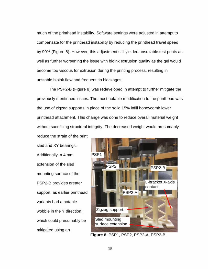
The PSP2-B (Figure 8) was redeveloped in attempt to further mitigate the
previously mentioned issues. The most notable modification to the printhead was
the use of zigzag supports in place of the solid 15% infill honeycomb lower
printhead attachment. This change was done to reduce overall material weight
without sacrificing structural integrity. The decreased weight would presumably
reduce the strain of the print
sled and XY bearings.
Additionally, a 4 mm
extension of the sled
mounting surface of the
PSP2-B provides greater
support, as earlier printhead
variants had a notable
wobble in the Y direction,
which could presumably be
mitigated using an
Figure 8: PSP1, PSP2, PSP2-A, PSP2-B.
L-bracket X-axis contact.
Zigzag support.
Sled mounting surface extension.
PSP1
PSP2
PSP2-A
PSP2-B
16
additional supporting lip, thus allowing the printhead to be better supported on
the XY shelf. Beyond these stability enhancements, the PSP2-B was given an L-
bracket protrusion on its lower-right surface and a reduced mid-section cross
plate. These modifications allowed the PSP2-B to make contact with the X-axis
positional switch without the need for additional modification of the 3D printer’s
existing X-axis switch as was required in earlier printhead variants. The mid-
section cross plate reduction was an attempt to minimize the overall printhead
weight as well as to minimize any accidental contact contamination during
syringe loading. Ultimately the reduced weight and stability enhancements did
not prove to be sufficient to stabilize the printhead nor to provide notable
improvement in the print quality.
The PSP3
The PSP3 (Figure 9) was designed to eliminate the top-heavy instability of
previous printhead designs. The direct injection method was abandoned after
over a year of development ultimately because it was not feasible with the
current hardware. Keeping this method would have required significant
modification of the 3D printer XY chassis yet still would likely have problems with
vibration in the XY axis print sled bearings. Additional likely problems might
include flexing in the steel guide rods as a result of the bio printhead’s large
stepper motors’ being mounted to the top of the syringe pump assembly,
resulting in instability and poor print quality. Even with software modifications
17
involving 90% reduced printhead travel speeds, test prints of simple circles were
of insufficient resolution (Figure 6).
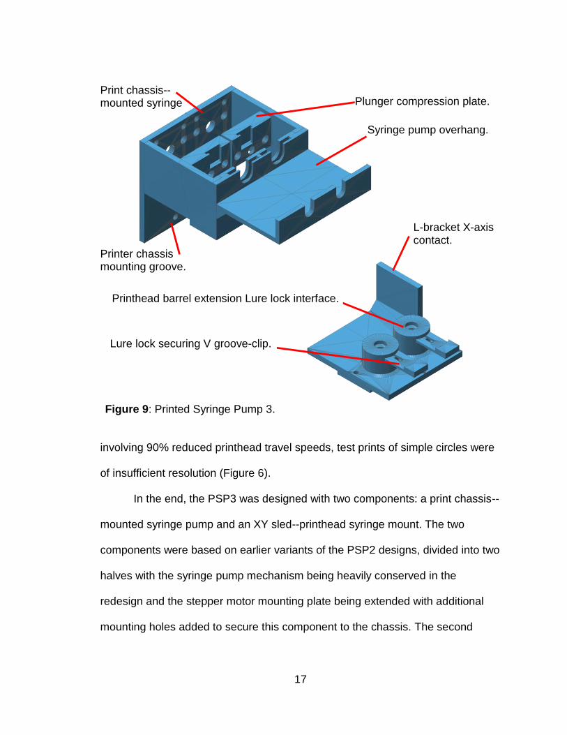
In the end, the PSP3 was designed with two components: a print chassis--
mounted syringe pump and an XY sled--printhead syringe mount. The two
components were based on earlier variants of the PSP2 designs, divided into two
halves with the syringe pump mechanism being heavily conserved in the
redesign and the stepper motor mounting plate being extended with additional
mounting holes added to secure this component to the chassis. The second
Figure 9: Printed Syringe Pump 3.
Syringe pump overhang.
Plunger compression plate.
Printhead barrel extension Lure lock interface.
Lure lock securing V groove-clip.
L-bracket X-axis contact.
Print chassis--mounted syringe pump.
Printer chassis mounting groove.
18
component was created using the PSP2’s print chassis mounting plate and L-
bracket X-axis contact. Additional modifications were included to provide luer
lock connections for printhead tip stability as syringes were no longer directly
mounted to the printhead, thus necessitating greater reinforcement to maintain
tip stability.
This configuration puts the bulk of the printhead’s weight (i.e. syringe
pump mechanism and stepper motors) onto the printer chassis, making use of
mounting points formerly used by cable guides in the printer’s factory hardware
setup. Screws were also repurposed to secure the syringe pump to the chassis.
The printhead sled was designed to make use of the luer lock groove profile to
provide additional support for the printhead itself while utilizing the PSP2-B’s XY
sled mounting profile and a modified X-axis contact switch--extension concept.
Initially the extruded bioink from the syringe pump was carried through
prepackaged sterile disposable IV extensions. These were hoped to minimize the
cost and steps of sterilization required for bioprinting. However, the high gauge
tubing and integrated valves used to prevent embolism created a bottleneck in
the bioink injector flow. This bottleneck impeded bioink flow to the point where
bioink of printable viscosity could not be extruded with the existing stepper
motors. Ultimately, traditional, inexpensive polyvinyl ⅛-inch tubing combined with
inexpensive, sterilizable, barbed, acrylic, male and female luer lock connectors
provided a more stable bioink flow at the cost of additional sterilization steps.
19
The printhead component, while being highly conserved from the PSP2
models, was modified to have a barrel extension with V groove slots matching
the luer lock connectors on the surgical tubing. This change allows a 3D printed
V clip to be placed in the slot for improved syringe tip stability. Moreover, this
design offers locking in the surgical tubing with a barbed acrylic luer lock, thus
decreasing the likelihood of connection failure from positional strain on the
tubing. Ultimately test prints with the PSP3 demonstrated the stability required for
higher resolution bio printed constructs to be generated.
Initial Testing of PSP2 and PSP3
Initial tests as with the PSP2s focused on printing 1 cm rings (Figure 6),
chosen for their ready ability to create simple, structurally sound shapes, in
addition to their proclivity in cell culture tests for ready media diffusion into
cultured cells. 120 mm polystyrene petri dishes were used to provide a
removable, sterile build surface. The petri dish lid was affixed to the printer build
platform with the application of a few drops of bioink as the capillary action
between the build surface and petri dish secured the lid in place. The build
surface was then manually adjusted on Z-axes to compensate for the thickness
of the petri dish. With several rings printing successfully, a more complex final
test print was chosen. The complex shape of a human ear was selected as its
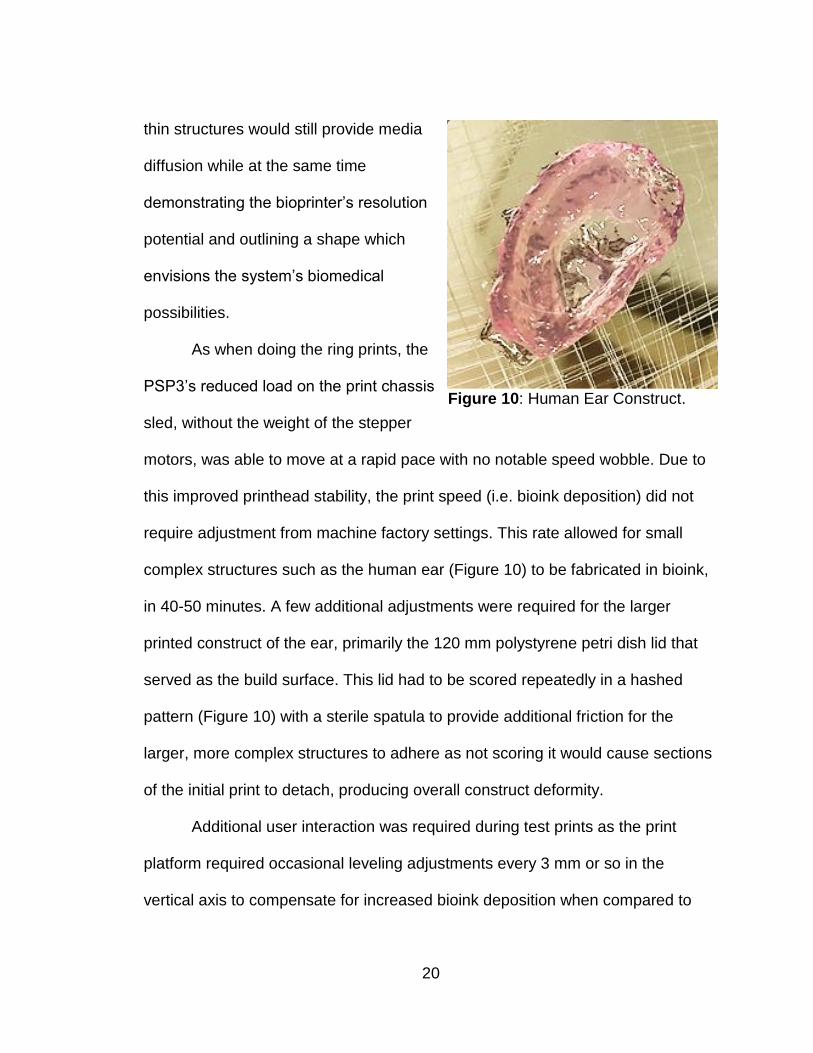
20
thin structures would still provide media
diffusion while at the same time
demonstrating the bioprinter’s resolution
potential and outlining a shape which
envisions the system’s biomedical
possibilities.
As when doing the ring prints, the
PSP3’s reduced load on the print chassis
sled, without the weight of the stepper
motors, was able to move at a rapid pace with no notable speed wobble. Due to
this improved printhead stability, the print speed (i.e. bioink deposition) did not
require adjustment from machine factory settings. This rate allowed for small
complex structures such as the human ear (Figure 10) to be fabricated in bioink,
in 40-50 minutes. A few additional adjustments were required for the larger
printed construct of the ear, primarily the 120 mm polystyrene petri dish lid that
served as the build surface. This lid had to be scored repeatedly in a hashed
pattern (Figure 10) with a sterile spatula to provide additional friction for the
larger, more complex structures to adhere as not scoring it would cause sections
of the initial print to detach, producing overall construct deformity.
Additional user interaction was required during test prints as the print
platform required occasional leveling adjustments every 3 mm or so in the
vertical axis to compensate for increased bioink deposition when compared to
Figure 10: Human Ear Construct.
21
the printer’s original plastic deposition. This issue was discovered early on. As
the print increased in height, vertical adjustments were required to maintain
resolution and to prevent the printhead from contacting and disturbing the
previously deposited bioink layers. Manual adjustment was required as the bioink
deposition flattening, and temporal curing profile vary with the viscosity of the
bioink.
Gelatin Bioink Development
Several different options were considered for the formulation of a bioink.
One commercially available bioink distributed by BioBots is a proprietary blend
based primarily on Poly (lactic-co-glycolic acid), or PLGA. Unfortunately, this
synthetic, biocompatible and biodegradable polymer is also $200 per gram
(www.biobots.io/, 2017). Other, more conventional tissue engineering materials
such as Thermo Fisher's Geltrex or Corning's Matrigel require high
concentrations for 3D cell culture and average around $50 per mL. Ultimately a
gelatin-based bioink was selected as the most cost-effective candidate that was
both highly biocompatible and mechanically suitable for use as a bioink. Gelatin
when combined with the enzyme microbial transglutaminase MTGase creates a
hydrogel that congeals at 37 °C. The resulting bioink costs less than $1 per mL
(Zhao, 2016).
22
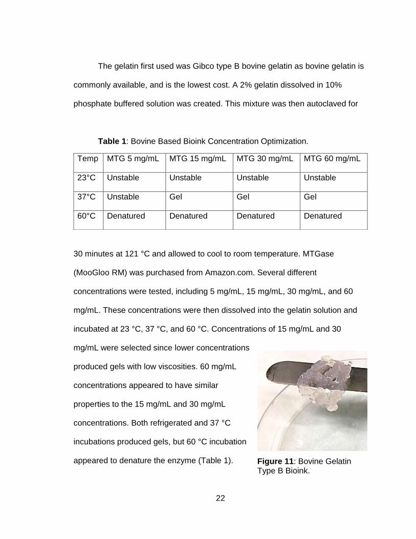
The gelatin first used was Gibco type B bovine gelatin as bovine gelatin is
commonly available, and is the lowest cost. A 2% gelatin dissolved in 10%
phosphate buffered solution was created. This mixture was then autoclaved for
Table 1: Bovine Based Bioink Concentration Optimization.
30 minutes at 121 °C and allowed to cool to room temperature. MTGase
(MooGloo RM) was purchased from Amazon.com. Several different
concentrations were tested, including 5 mg/mL, 15 mg/mL, 30 mg/mL, and 60
mg/mL. These concentrations were then dissolved into the gelatin solution and
incubated at 23 °C, 37 °C, and 60 °C. Concentrations of 15 mg/mL and 30
mg/mL were selected since lower concentrations
produced gels with low viscosities. 60 mg/mL
concentrations appeared to have similar
properties to the 15 mg/mL and 30 mg/mL
concentrations. Both refrigerated and 37 °C
incubations produced gels, but 60 °C incubation
appeared to denature the enzyme (Table 1).
Temp MTG 5 mg/mL MTG 15 mg/mL MTG 30 mg/mL MTG 60 mg/mL
23°C Unstable Unstable Unstable Unstable
37°C Unstable Gel Gel Gel
60°C Denatured Denatured Denatured Denatured
Figure 11: Bovine Gelatin Type B Bioink.
23
Successful gels were then soaked in PBS
over 72 hours to confirm they did not
dissolve (Figure 11). Unfortunately, when
the experiment was repeated with gels
being submerged in DMEM culture media,
the gel dissolved. Both integration into
uncongealed gel, as well as submersion of
completed gel, showed the same results.
After further literature review, type B
gelatin was found to have been processed using a different technique which
resulted in chemical differences making it unsuitable for cell culture.
Corning type A porcine gelatin was then selected. Concentration
optimization was repeated with the porcine gelatin with similar results. Ultimately
15 mg/mL and 30 mg/mL MTGase and 2% porcine type A 10% PBS solutions
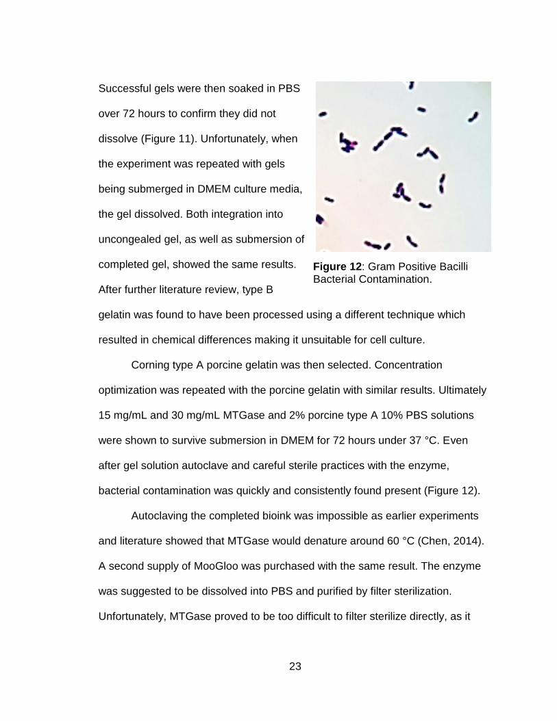
were shown to survive submersion in DMEM for 72 hours under 37 °C. Even
after gel solution autoclave and careful sterile practices with the enzyme,
bacterial contamination was quickly and consistently found present (Figure 12).
Autoclaving the completed bioink was impossible as earlier experiments
and literature showed that MTGase would denature around 60 °C (Chen, 2014).
A second supply of MooGloo was purchased with the same result. The enzyme
was suggested to be dissolved into PBS and purified by filter sterilization.
Unfortunately, MTGase proved to be too difficult to filter sterilize directly, as it
Figure 12: Gram Positive Bacilli Bacterial Contamination.
24
was too thick. Ultraviolet sterilization using a UV crosslinker at exposures of 10,
20, and 30 minutes was tested, but the contamination persisted. Several pre-
filters were used from 40 μm, 2 μm, 0.45 μm, to 0.22 μm, which resulted in a
significant loss of the initial solution. The MTGase solution was then centrifuged
as a pre-filtration step. Centrifuge speeds of 5,000 RPM for 5, 10, and 15
minutes were tested, however, this did not result in a filterable solution. A
centrifuge speed of 9,500 RPM for 20 minutes resulted in an MTGase solution
that could be effectively filter sterilized with a 0.22 μm syringe filter.
Later bioink cost optimizations found that 3,000 RPM centrifugation for 60
minutes provided a supernatant that was filter sterilizable at speeds that could be
obtained using conventional low-cost desktop centrifuges. In addition to cost
optimizing MTGase filter sterilization, porcine gelatin sterilization was also cost
optimized as 60 °C for 60 minutes of hot plate gel dissolution combined with filter
sterilization, proving to be as effective as the previous autoclaving protocol and
ultimately eliminating the need for laboratory autoclaving altogether. This finding
further highlights the financial feasibility of this bioink for under-funded and or
under-equipped laboratory facilities. The centrifuged MTGase solution and
porcine gelatin solution were filter sterilized in hood.
The final developed bioink loading protocol required immediate filter
sterilization of the gelatin into a 12 mL sterile conical tube. Any delay increased
gel viscosity inhibiting filtration. Next the MTGase supernatant was syringe filter
sterilized directly into the filtered bioink. The bioink was then agitated via pipette
25
to intermix, and 9 mL of bioink was
then transferred into 1 mL of cell-
laden DMEM. The result was then
agitated via pipette, and then 10 mL
of the resulting cell-laden bioink was
pipetted into a sterile 10 mL syringe.
The syringe was then lure-locked to
the sterile syringe tip and ⅛-inch
tubing assembly and was
compressed to remove any remaining inline DMEM used previously to flush the
print tip assembly. The bioink was left to congeal to a viscosity where syringe air
bubbles could not migrate when the syringe was inverted.
In the following phase, cells were cultured and transferred into the 15
mg/mL and 30 mg/mL concentration gels to investigate visually any possible
cytotoxic effects of the enzyme. The gels were created and transferred into
Corning culturing flasks with NIH3T3 cells. After six days there was no observed
change in cell morphology in either of the two concentration groups (Nguyen,
2017). This experiment was repeated with cells that were freshly seeded into the
flasks. The cells again showed no differences in morphology. Additionally, there
were no observed differences in either cell adhesion or time to confluency. The
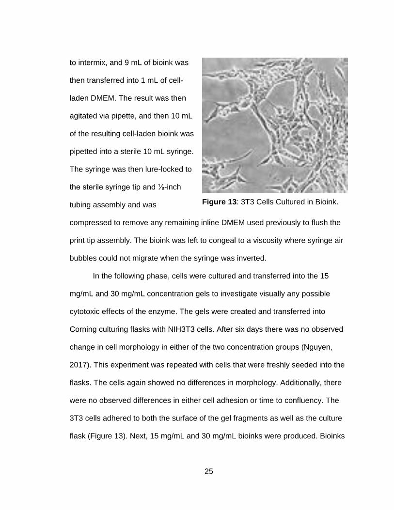
3T3 cells adhered to both the surface of the gel fragments as well as the culture
flask (Figure 13). Next, 15 mg/mL and 30 mg/mL bioinks were produced. Bioinks
Figure 13: 3T3 Cells Cultured in Bioink.
26
were allowed to incubate for 3 hours prior to cell introduction. Cells were
detached from flasks by using 1 mL 1% trypsin for 30 seconds and then
resuspended with the addition of 4 mL of DMEM. Cells were taken from two 80%
confluent flasks. Cells were then put into a 15 mL conical tube and spun down to
form a pellet. The media was siphoned off, and the cells were resuspended in 1
mL of DMEM. The cell suspension was then added to the bioink, pipetted into a
Corning six-well plate and incubated for 30 minutes for 30 mg/mL and 60 minutes
for 15 mg/mL 4 mL DMEM was then pipetted dropwise onto the gels, which were
then incubated at 37 °C for six days. Cell survival and proliferation were then
observed. Cells exhibited a healthy morphology within the bioink. There was no
observable difference between the 15 mg/mL and 30 mg/mL concentration
bioinks. Upper layers of the bioink were found to be subject to fungal
contamination. The experiment was repeated a second time with the same
results. A third repeat of the experiment was conducted; however, flasks were
used in place of plates; fungal contamination was not observed. Ultimately, 30
mg/mL MTGase with 2% porcine gelatin in 10% PBS was selected as the best
candidate bioink (Figure 15).
Syringe Loading and Tip Optimization
27
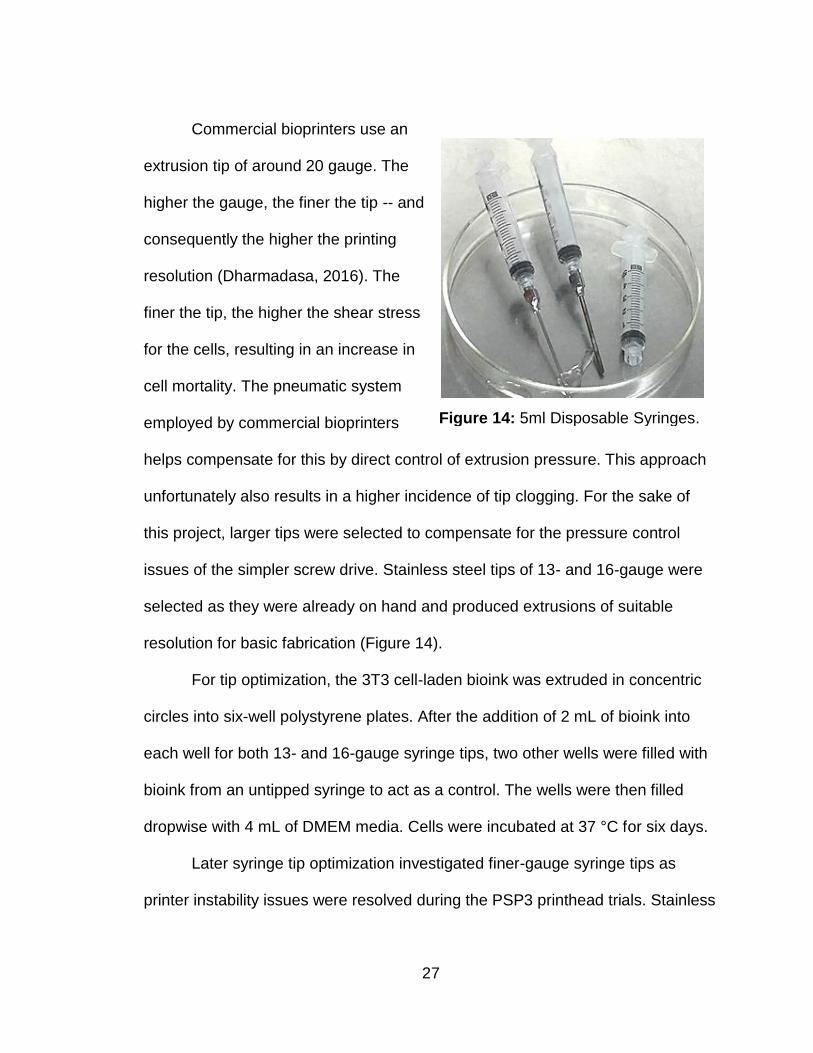
Commercial bioprinters use an
extrusion tip of around 20 gauge. The
higher the gauge, the finer the tip -- and
consequently the higher the printing
resolution (Dharmadasa, 2016). The
finer the tip, the higher the shear stress
for the cells, resulting in an increase in
cell mortality. The pneumatic system
employed by commercial bioprinters
helps compensate for this by direct control of extrusion pressure. This approach
unfortunately also results in a higher incidence of tip clogging. For the sake of
this project, larger tips were selected to compensate for the pressure control
issues of the simpler screw drive. Stainless steel tips of 13- and 16-gauge were
selected as they were already on hand and produced extrusions of suitable
resolution for basic fabrication (Figure 14).
For tip optimization, the 3T3 cell-laden bioink was extruded in concentric
circles into six-well polystyrene plates. After the addition of 2 mL of bioink into
each well for both 13- and 16-gauge syringe tips, two other wells were filled with
bioink from an untipped syringe to act as a control. The wells were then filled
dropwise with 4 mL of DMEM media. Cells were incubated at 37 °C for six days.
Later syringe tip optimization investigated finer-gauge syringe tips as
printer instability issues were resolved during the PSP3 printhead trials. Stainless
Figure 14: 5ml Disposable Syringes.
28
steel syringe tips were purchased and tested ranging from 12 - 28 gauge. These
tips are commonly available at hobby stores as they are used for precision
adhesive applications. Tip optimization was then performed again this time
investigating 18 and 20-gauge syringe tips. 20-gauge, 1-inch tips were
determined optimal as they allowed for extrusion of the higher viscosity bioink
necessary for print integrity while maximizing cell viability. 20-gauge also closely
matches the printer’s factory 26-gauge print tip extrusion size, eliminating the
need for factory software modification. The easily available, low-cost, stainless
steel luer lock fitting and factory-cut, 1-inch length made these adhesive-
applying syringe tips ideal for this project.
The initial protocol developed for syringe loading involved intermixing the
gelatin and enzyme and allowing incubation for three hours at 37 °C, followed by
intermixing the bioink with 3T3 cells resuspended in DMEM. The mixture was
then drawn into 5 mL disposable syringes and placed into a Pyrex petri dish for
an additional hour until reaching a semi-viscous state. The extrusion tips were
then attached to the disposal syringes.
Later, syringe tip assembly and system sterilization protocols were
optimized. Sterilization of the printer platform and exposed surfaces applied 70%
ethanol spray while male and female luer locks, the printing syringe tip, and
polyvinyl tubing all required submersion in 70% ethyl alcohol. These components
were then flushed via syringe with additional alcohol to ensure there were no
internal air pockets. After approximately one-hour submersion (i.e. the time
29
required for the sterilized printer hardware to dry to the point of safe system
power-up) the submerged components were then assembled and flushed with 20
mL of sterile DMEM to ensure no remaining alcohol was present in the assembly.
This sterilization protocol was chosen as it did not require the use of an autoclave
and as such would greatly reduce the secondary equipment cost of the printing
system, allowing it to be more accessible to underfunded facilities.
The optimized bioink mentioned earlier was then loaded into the
disposable syringes and relocked to the alcohol-sterilized and DMEM-flushed
print tip assembly. Bioink was then extruded, flushing out any remaining inline
DMEM. The loaded printhead assembly was then allowed to air incubate for 45
minutes, or until bioink reached sufficient viscosity that syringe air bubbles could
not migrate when the syringe was inverted. Room temperature bioink incubation
proved to greatly cell-laden bioink gelation time from the original 3 hours at 37 °C
protocol down to 45 minutes while also reducing the possibility of accidental
contamination.
30
CHAPTER THREE
PROJECT DATA
Optimization Data
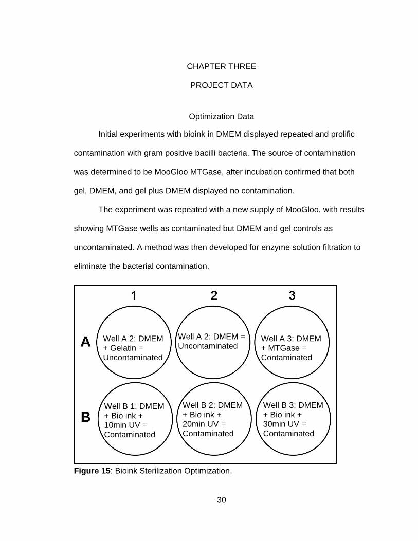
Initial experiments with bioink in DMEM displayed repeated and prolific
contamination with gram positive bacilli bacteria. The source of contamination
was determined to be MooGloo MTGase, after incubation confirmed that both
gel, DMEM, and gel plus DMEM displayed no contamination.
The experiment was repeated with a new supply of MooGloo, with results
showing MTGase wells as contaminated but DMEM and gel controls as
uncontaminated. A method was then developed for enzyme solution filtration to
eliminate the bacterial contamination.
Figure 15: Bioink Sterilization Optimization.
Well A 2: DMEM + Gelatin = Uncontaminated
Well A 2: DMEM = Uncontaminated
Well A 3: DMEM + MTGase = Contaminated
Well B 3: DMEM + Bio ink + 30min UV = Contaminated
Well B 2: DMEM + Bio ink + 20min UV = Contaminated
Well B 1: DMEM + Bio ink + 10min UV = Contaminated
31
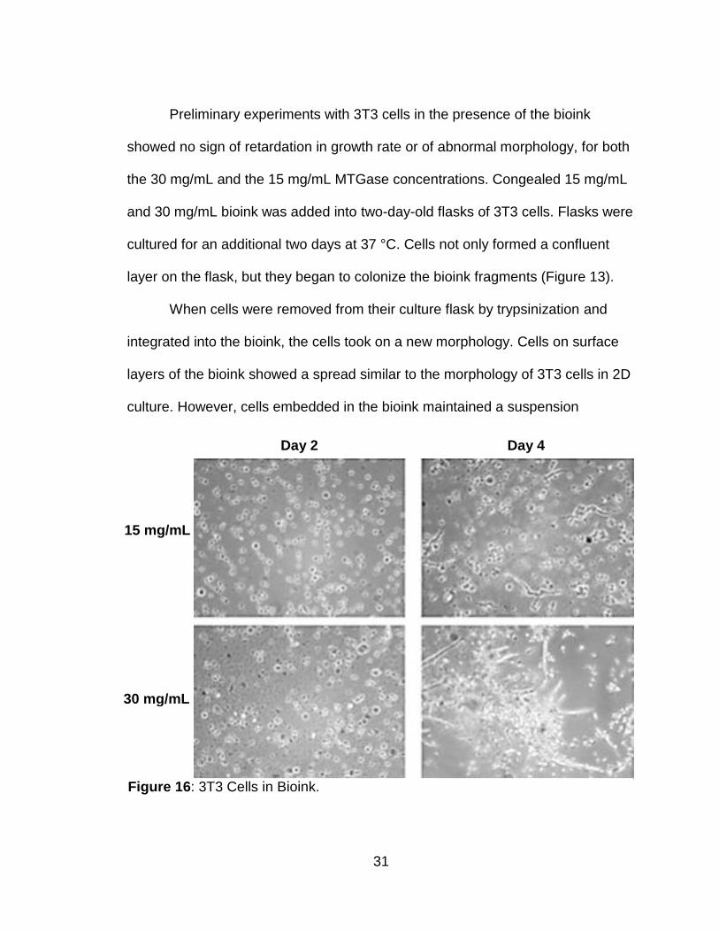
Preliminary experiments with 3T3 cells in the presence of the bioink
showed no sign of retardation in growth rate or of abnormal morphology, for both
the 30 mg/mL and the 15 mg/mL MTGase concentrations. Congealed 15 mg/mL
and 30 mg/mL bioink was added into two-day-old flasks of 3T3 cells. Flasks were
cultured for an additional two days at 37 °C. Cells not only formed a confluent
layer on the flask, but they began to colonize the bioink fragments (Figure 13).
When cells were removed from their culture flask by trypsinization and
integrated into the bioink, the cells took on a new morphology. Cells on surface
layers of the bioink showed a spread similar to the morphology of 3T3 cells in 2D
culture. However, cells embedded in the bioink maintained a suspension
Figure 16: 3T3 Cells in Bioink.
Day 2 Day 4
15 mg/mL
30 mg/mL
32
morphology. The cells did not stretch out and remained spherical. After seven
days in incubation, networks of fungal hyphae began to spread out from surface
layers of the bioink. The fungal contamination was present on both the 15 mg/mL
and 30 mg/mL MTGase conditions, but not in the 3T3 cell culture flasks. As there
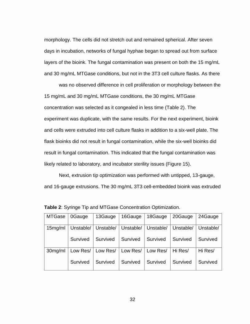
was no observed difference in cell proliferation or morphology between the
15 mg/mL and 30 mg/mL MTGase conditions, the 30 mg/mL MTGase
concentration was selected as it congealed in less time (Table 2). The
experiment was duplicate, with the same results. For the next experiment, bioink
and cells were extruded into cell culture flasks in addition to a six-well plate. The
flask bioinks did not result in fungal contamination, while the six-well bioinks did
result in fungal contamination. This indicated that the fungal contamination was
likely related to laboratory, and incubator sterility issues (Figure 15).
Next, extrusion tip optimization was performed with untipped, 13-gauge,
and 16-gauge extrusions. The 30 mg/mL 3T3 cell-embedded bioink was extruded
MTGase 0Gauge 13Gauge 16Gauge 18Gauge 20Gauge 24Gauge
15mg/ml Unstable/
Survived
Unstable/
Survived
Unstable/
Survived
Unstable/
Survived
Unstable/
Survived
Unstable/
Survived
30mg/ml Low Res/
Survived
Low Res/
Survived
Low Res/
Survived
Low Res/
Survived
Hi Res/
Survived
Hi Res/
Survived
Table 2: Syringe Tip and MTGase Concentration Optimization.
33
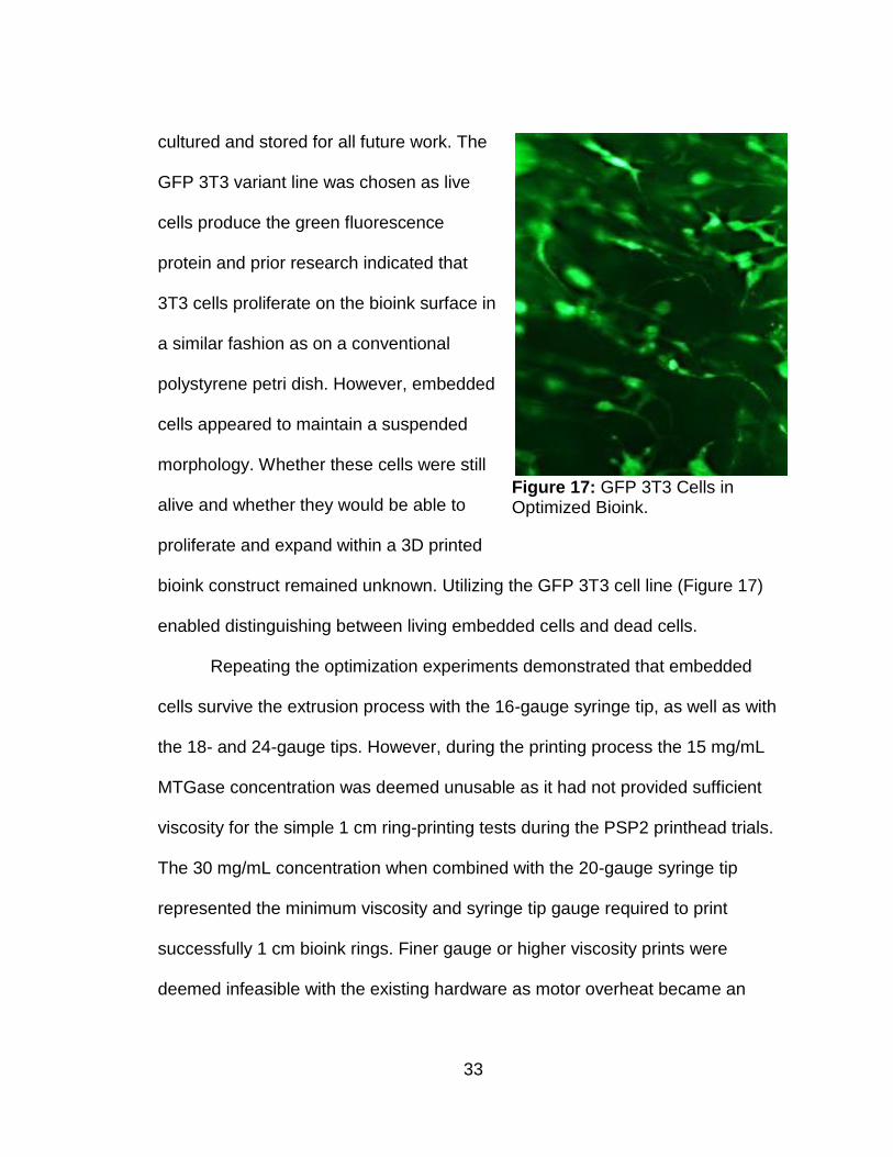
cultured and stored for all future work. The
GFP 3T3 variant line was chosen as live
cells produce the green fluorescence
protein and prior research indicated that
3T3 cells proliferate on the bioink surface in
a similar fashion as on a conventional
polystyrene petri dish. However, embedded
cells appeared to maintain a suspended
morphology. Whether these cells were still
alive and whether they would be able to
proliferate and expand within a 3D printed
bioink construct remained unknown. Utilizing the GFP 3T3 cell line (Figure 17)
enabled distinguishing between living embedded cells and dead cells.
Repeating the optimization experiments demonstrated that embedded
cells survive the extrusion process with the 16-gauge syringe tip, as well as with
the 18- and 24-gauge tips. However, during the printing process the 15 mg/mL
MTGase concentration was deemed unusable as it had not provided sufficient
viscosity for the simple 1 cm ring-printing tests during the PSP2 printhead trials.
The 30 mg/mL concentration when combined with the 20-gauge syringe tip
represented the minimum viscosity and syringe tip gauge required to print
successfully 1 cm bioink rings. Finer gauge or higher viscosity prints were
deemed infeasible with the existing hardware as motor overheat became an
Figure 17: GFP 3T3 Cells in Optimized Bioink.
34
apparent issue. A 20-gauge syringe tip with 30 mg/mL concentration comprised
the minimum requirement for stable, adequate resolution bioprinting as well as
the upper limit of the current hardware’s extrusion capabilities. This combination
of print tip and bioink formulation was chosen for testing with both the simple 1
cm ring-printing tests as well as the eventual, more complicated ear-printing
tests.
Test rings were printed as a method for optimizing printer hardware
configuration as well as for fine tuning printer software settings. The 3D models
were imported into the native factory slicing software FlashPrint developed for
use with the Creator Pro series desktop 3D printers. 3D models could easily be
manipulated in this software environment while print settings such as build
speed, printhead deposition rate, and infill could be adjusted and reported
directly to the printer (Figure 6). These features greatly simplified the process of
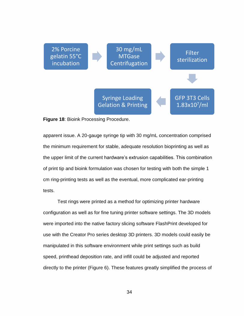
2% Porcine gelatin 55°Cincubation
30 mg/mL MTGase
Centrifugation
Filter sterilization
GFP 3T3 Cells 1.83x10⁷/ml
Syringe Loading Gelation & Printing
Figure 18: Bioink Processing Procedure.
35
system and model optimization. Although printhead and bioink viscosity
formulations were optimized by looking at cell survival, ultimately, they
represented the mechanical limits of the system (i.e. the best resolution and
material integrity that could be printed without overtaxing the printer’s extrusion
stepper motors).
Cell survival was compared between extruded and non-extruded bioinks
to find parameters that yielded sufficient survival. GFP 3T3 cells were later
investigated to obtain a better understanding of embedded cell survival within the
3D printed constructs. GFP cells were chosen for assessing cell survival and
proliferation as conventional staining methods like tryphan blue are toxic to cell
survival and would likely require multiple constructs to be produced and cross
sectioned over time. Alternatively, cell tracking fluorescent probes such as
thermofisher’s CellTracker Blue CMAC allows for live cell tracking over time, with
a portion of the probes being transferred over several cell divisions, however this
method is costly with the least expensive probe being 270$ for 5 mL.
Additionally, it was unknown if complications would arise, such as reduced cell
count accuracy as each generations probe concertation decreased, or if the
probes function would be effected by the presence of the MTGase.
Final Project Data
The final experiment investigated cell survival and proliferation between
extruded and non-extruded GFP 3T3 cell-laden bioinks. The bioprinter and
36
extrusion assembly sterilization protocol as stated in previous sections was
conducted. 3T3 GFP second passage cells were cultured and integrated with the
bioink at a concentration of 1.83x10⁷/mL at a ratio of 95% living cells. 5 mL of
cell-infused bioink was loaded into a syringe for printing purposes (Figure 18).
The remaining 5 mL was transferred into a 6-well plate. The printer
incubated the bioink at room temperature for 45 minutes until printing viscosity
was reached, then bioink was deposited by the bioprinter at a rate of 1 mL per 10
minutes. The resulting ear was completed after 50 minutes. Once the ear was
completed, it was removed using a sterile spatula and placed in the 6-well plate.
Both the bio printed ear and non-extruded bioink was then submerged in 10 mL
of DMEM media with 20% serum as recommended by the cell line manufacturer.
The 6-well plate was then cultured for 17 days under standard mammalian tissue
culturing conditions. Cell survival was assessed via GFP cell counting with
ImageJ. Specific locations were imaged repeatedly over the 17-day period at 3-
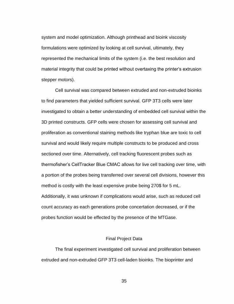
Figure 19: ImageXpress Z-Stack Well Locations Diagram.
37
day
intervals with the use of ImageXpress micro-robotic microscope system by
Molecular Devices. 5 separate locations for both the unprinted bioink control and
the printed construct were selected (Figure 19). Each location had 15 images
taken on different focal planes. Each location and focal plane were then
reimaged via a computerized imaging protocol on subsequent days. All resulting
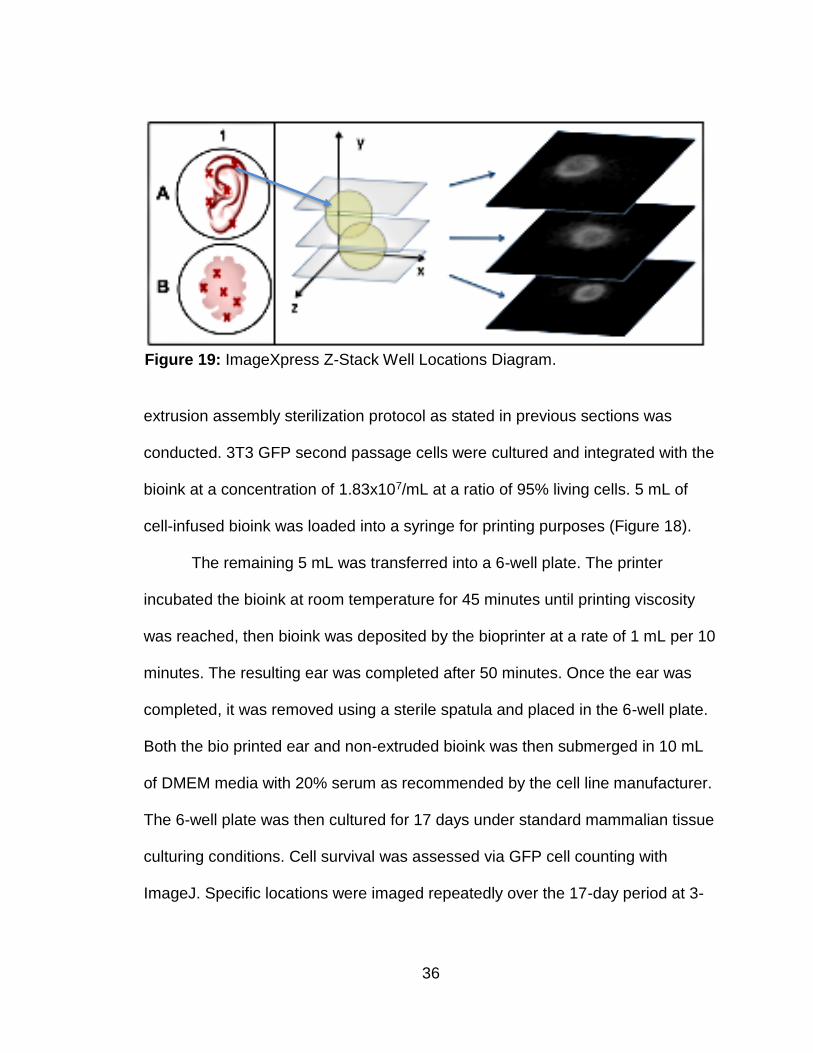
GFP images were then analyzed by ImageJ to create Z-stacks for each location
(Figure 20). These image stacks were then subdivided into three zones --
bottom, middle, and top. Each Z-stack was then analyzed via a custom cell-
counting macro created for ImageJ by Terisa Ubina (Bournias-V. lab). Resulting
data was then exported into a spreadsheet for analysis.
Previous experiments demonstrated that the optimized bioink was
sufficiently biocompatible as to allow 3T3 cell proliferation from within extruded
constructs however they did not track cell counts over time or compare cell
survival at relative depths within the bioink material.
Figure 20: ImageJ Z-Stack Cell Counting Macro.
38
The initial cell counts between the extruded bioink and the non-extruded
control bioink had a noteworthy difference in initial cell concentrations. This
difference was likely due to settling of cells in the bioink prior to pipetting, with the
extruded bioink having on average 40 to 50 more cells in the 20x viewing area of
the microscope. Unprinted bioink had only a modest average increase in cell
count from day 3 to day 6, with an overall decreasing trend in living cell counts
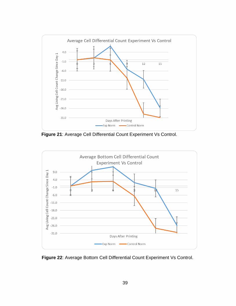
after day 9 (Figure 21). Printed bioink, however, demonstrated overall GFP cell
proliferation until day 9 when cell counts declined. The trends in both the
experimental and control group were obtained by averaging each of the three
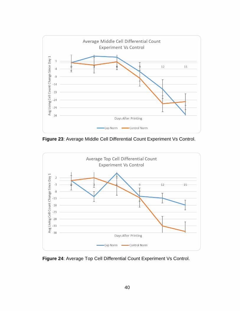
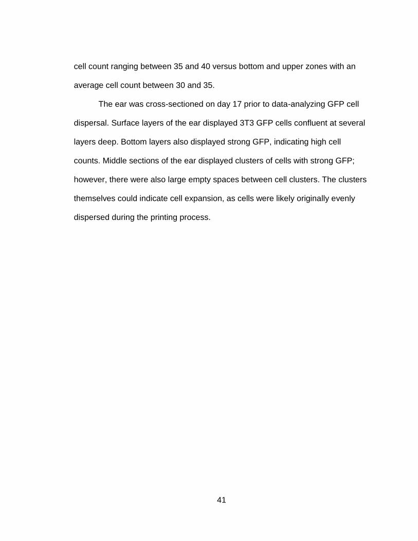
depth zones. Similar trends were found in both the bottom (Figure 22) and the
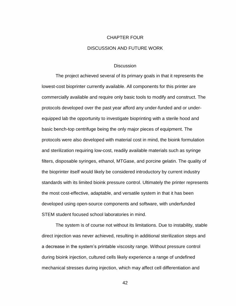
middle zones (Figure 23) when analyzed individually in either group. However,
the experimental top zone average cell count displayed a reduction in living GFP
cells between day 3 and day 6, with cell proliferation increasing in the view field
between days 6 and 9. Cell loss was also less pronounced between days 9 and
17 than during prior periods. Cells for experimental bottom and middle zones had
the greatest GFP density, likely indicating a greater cell density. However,
between days 12 and 15 the average cell loss in these zones outpaced the top
zone. Top zone averages for the experimental group had an average GFP cell
count of 80 cells in the visible area, with middle and bottom zones averaging
between 70 and 75 GFP cells in the visible field (Figure 24). Extruded control
cells followed a more consistent decline than their experimental counterparts
while middle zone cells between day 12 and day 15 rebounded with an average
39
Figure 21: Average Cell Differential Count Experiment Vs Control.
Figure 22: Average Bottom Cell Differential Count Experiment Vs Control.
40
Figure 23: Average Middle Cell Differential Count Experiment Vs Control.
Figure 24: Average Top Cell Differential Count Experiment Vs Control.
41
cell count ranging between 35 and 40 versus bottom and upper zones with an
average cell count between 30 and 35.
The ear was cross-sectioned on day 17 prior to data-analyzing GFP cell
dispersal. Surface layers of the ear displayed 3T3 GFP cells confluent at several
layers deep. Bottom layers also displayed strong GFP, indicating high cell
counts. Middle sections of the ear displayed clusters of cells with strong GFP;
however, there were also large empty spaces between cell clusters. The clusters
themselves could indicate cell expansion, as cells were likely originally evenly
dispersed during the printing process.
42
CHAPTER FOUR
DISCUSSION AND FUTURE WORK
Discussion
The project achieved several of its primary goals in that it represents the
lowest-cost bioprinter currently available. All components for this printer are
commercially available and require only basic tools to modify and construct. The
protocols developed over the past year afford any under-funded and or under-
equipped lab the opportunity to investigate bioprinting with a sterile hood and
basic bench-top centrifuge being the only major pieces of equipment. The
protocols were also developed with material cost in mind, the bioink formulation
and sterilization requiring low-cost, readily available materials such as syringe
filters, disposable syringes, ethanol, MTGase, and porcine gelatin. The quality of
the bioprinter itself would likely be considered introductory by current industry
standards with its limited bioink pressure control. Ultimately the printer represents
the most cost-effective, adaptable, and versatile system in that it has been
developed using open-source components and software, with underfunded
STEM student focused school laboratories in mind.
The system is of course not without its limitations. Due to instability, stable
direct injection was never achieved, resulting in additional sterilization steps and
a decrease in the system’s printable viscosity range. Without pressure control
during bioink injection, cultured cells likely experience a range of undefined
mechanical stresses during injection, which may affect cell differentiation and
43
propagation. Mechanical stresses that the cells are exposed to during the printing
process vary from print to print as temperature, humidity, starting bioink viscosity,
and print duration have the potential to change the compressive and sheer stress
profile the cells are exposed to during the printing process.
One obvious issue during the final experiment was cell dispersal variation
in the bioink itself. As the cells settled in the bioink, there was a large
discrepancy between the unprinted control bioink and the printed bioink. This
variation was likely found in the prints themselves with the lower layers having
higher initial cell counts in a gradient from the initial layers of the bio printed
construct to the final upper layers. Indeed, this effect was indicated in the data
with the lower and middle layers having a greater initial GFP density on average
than the upper layer. Ideally, a multi-injection tip would be utilized to minimize
this effect, with bioink and cells being intermixed during the printing process. This
approach would allow for smoother cell distribution while permitting the cells to
be kept in the cell-friendly environment of a bioreactor until they are needed, thus
improving cell viability. Earlier attempts to use the 3D printer’s heating elements
were unsuccessful as the 37 °C environment impeded initial gelation of the
bioink.
Future Work
This project did not pursue several important avenues of investigation.
Defining the mechanical forces, the cells are exposed to in both the pre and post
44
printing environment. Quantitative measurements of these mechanical stresses
and better control of environmental and procedural variables could be potentially
used to further optimize and differentiate bioink formulations for specific stem cell
line applications.
Additional modifications to the printer could also be pursued. With a
combination of Arduino controlled leveling stepper motors and optical positioning
sensors, the build platform could be automatically leveled during the printing
process potentially further improving print quality. Piezoelectric sensors could be
implemented to monitor bioink pressure in the current system allowing for bioink
injection pressures to be maintained within a predefined range, reducing the
potential variation in mechanical stresses cells are exposed to during the printing
process.
45
APPENDIX A
AVERAGE CELL COUNT DATA GRAPHS
46
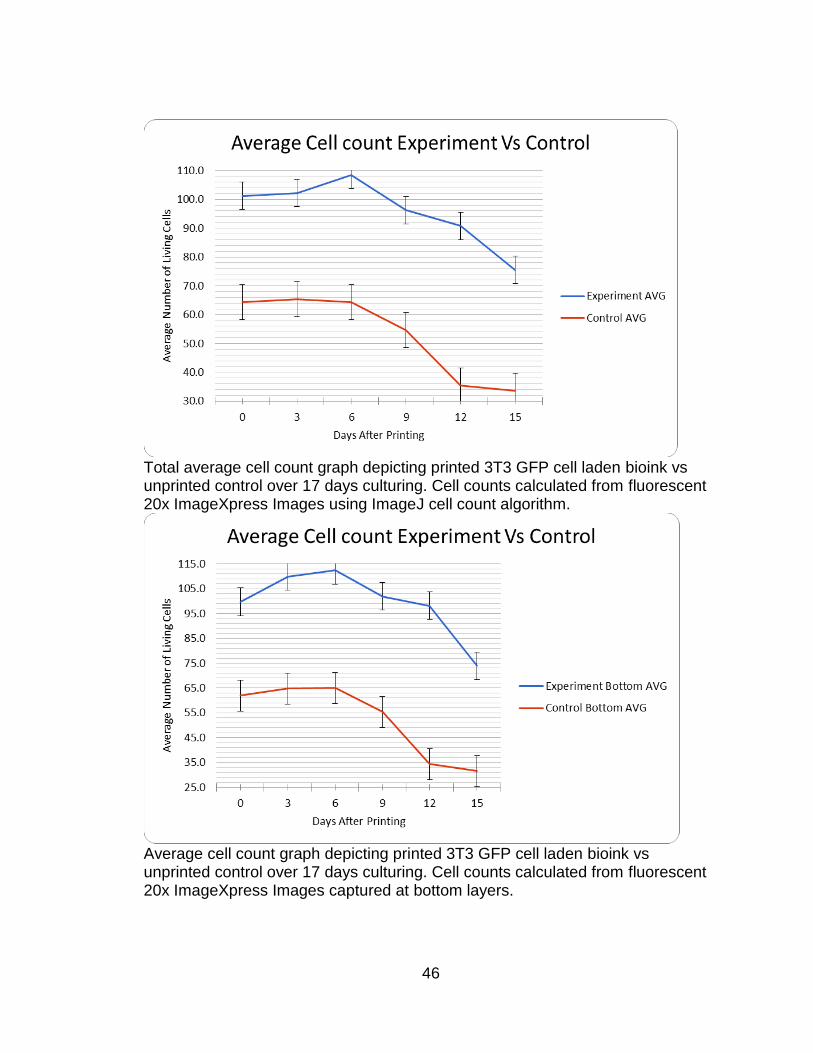
Total average cell count graph depicting printed 3T3 GFP cell laden bioink vs unprinted control over 17 days culturing. Cell counts calculated from fluorescent 20x ImageXpress Images using ImageJ cell count algorithm.
Average cell count graph depicting printed 3T3 GFP cell laden bioink vs unprinted control over 17 days culturing. Cell counts calculated from fluorescent 20x ImageXpress Images captured at bottom layers.
47
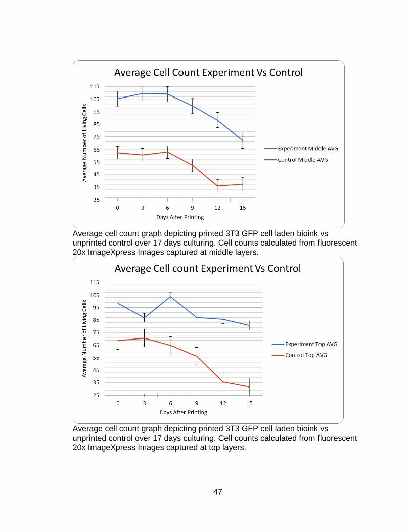
Average cell count graph depicting printed 3T3 GFP cell laden bioink vs unprinted control over 17 days culturing. Cell counts calculated from fluorescent 20x ImageXpress Images captured at middle layers.
Average cell count graph depicting printed 3T3 GFP cell laden bioink vs unprinted control over 17 days culturing. Cell counts calculated from fluorescent 20x ImageXpress Images captured at top layers.
48
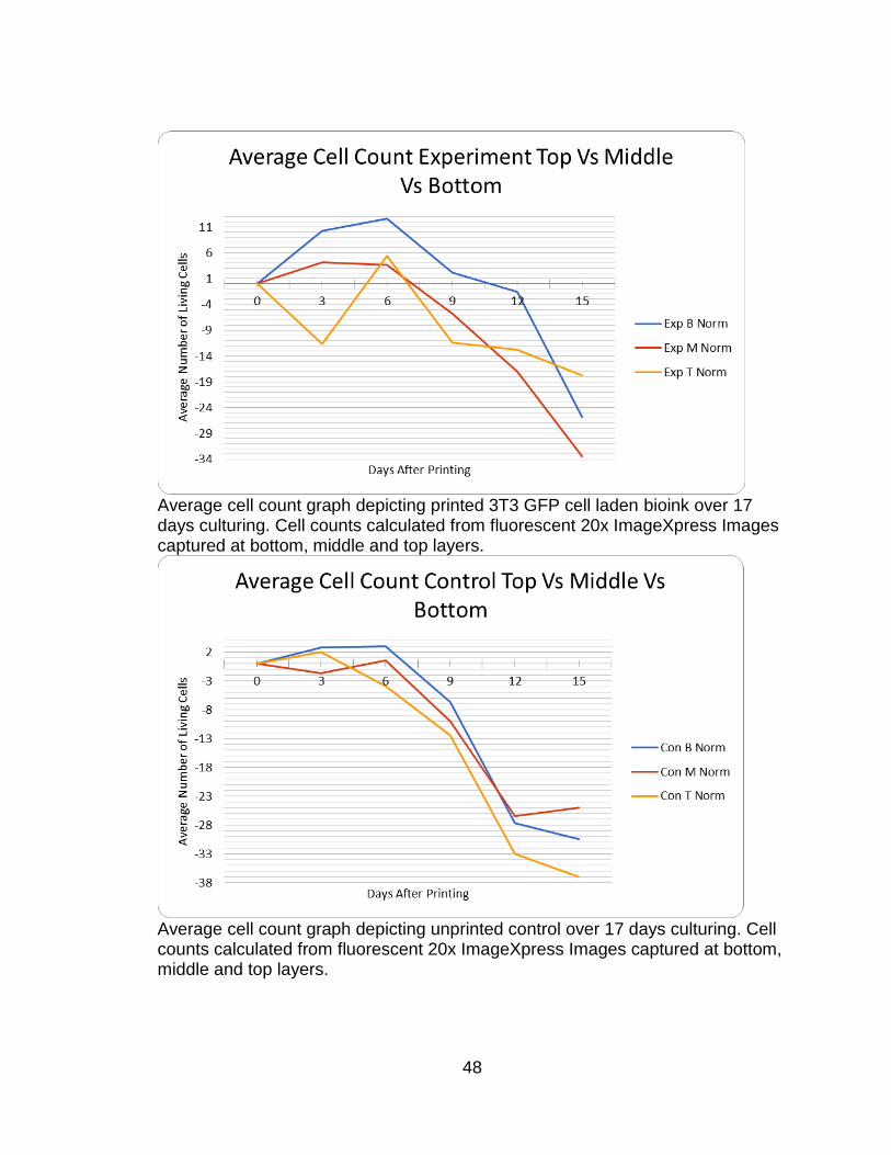
Average cell count graph depicting printed 3T3 GFP cell laden bioink over 17 days culturing. Cell counts calculated from fluorescent 20x ImageXpress Images captured at bottom, middle and top layers.
Average cell count graph depicting unprinted control over 17 days culturing. Cell counts calculated from fluorescent 20x ImageXpress Images captured at bottom, middle and top layers.

49
APPENDIX B
IMAGEXPRESS AND IMAGEJ DATA
50
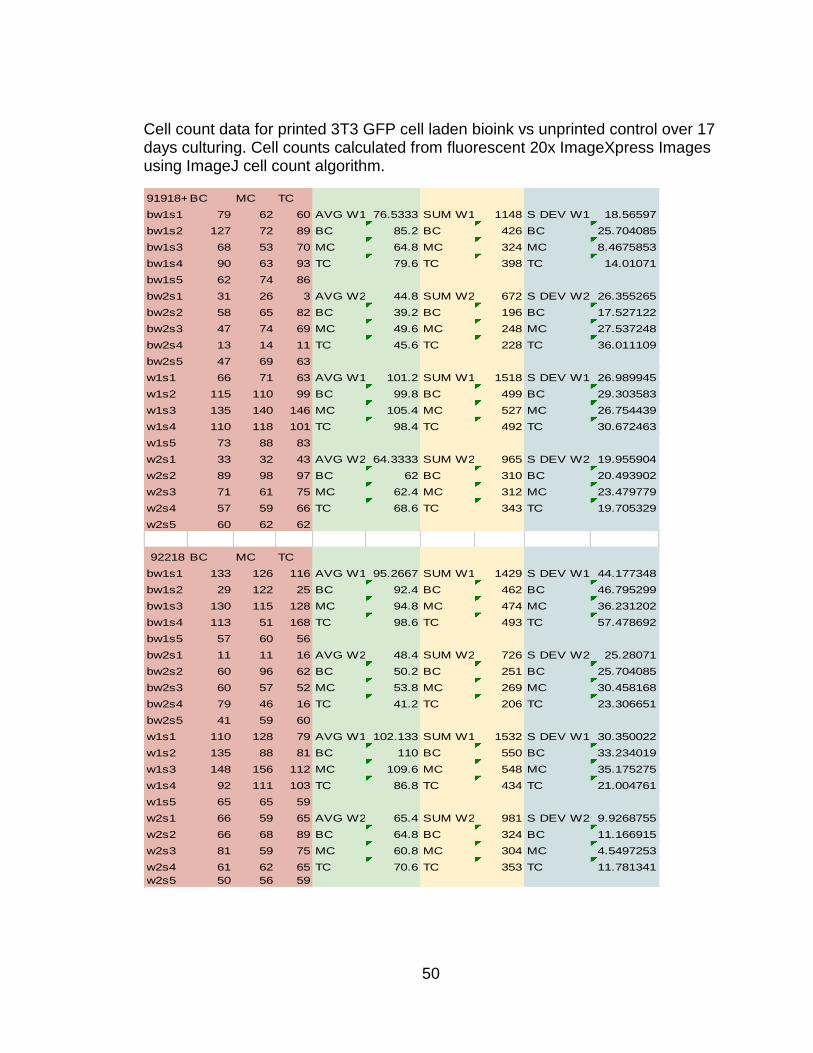
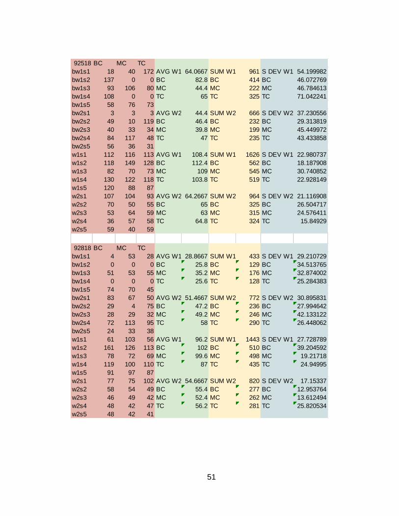
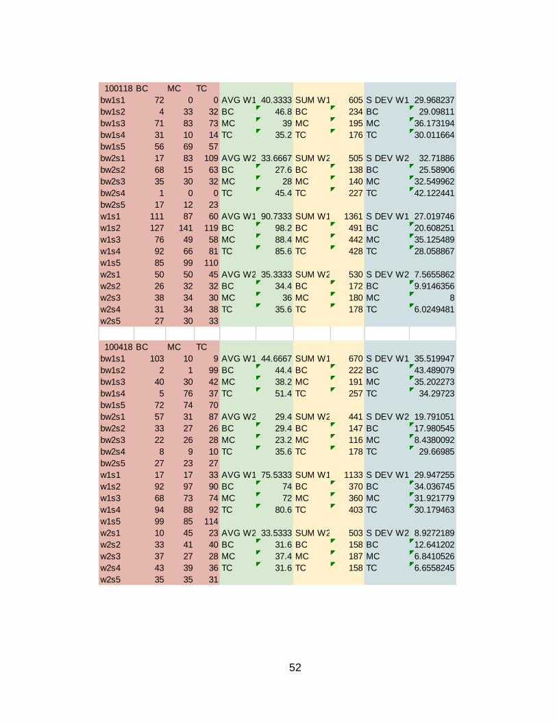
Cell count data for printed 3T3 GFP cell laden bioink vs unprinted control over 17 days culturing. Cell counts calculated from fluorescent 20x ImageXpress Images using ImageJ cell count algorithm.
91918+A1:J21BC MC TC
bw1s1 79 62 60 AVG W1 76.5333 SUM W1 1148 S DEV W1 18.56597
bw1s2 127 72 89 BC 85.2 BC 426 BC 25.704085
bw1s3 68 53 70 MC 64.8 MC 324 MC 8.4675853
bw1s4 90 63 93 TC 79.6 TC 398 TC 14.01071
bw1s5 62 74 86
bw2s1 31 26 3 AVG W2 44.8 SUM W2 672 S DEV W2 26.355265
bw2s2 58 65 82 BC 39.2 BC 196 BC 17.527122
bw2s3 47 74 69 MC 49.6 MC 248 MC 27.537248
bw2s4 13 14 11 TC 45.6 TC 228 TC 36.011109
bw2s5 47 69 63
w1s1 66 71 63 AVG W1 101.2 SUM W1 1518 S DEV W1 26.989945
w1s2 115 110 99 BC 99.8 BC 499 BC 29.303583
w1s3 135 140 146 MC 105.4 MC 527 MC 26.754439
w1s4 110 118 101 TC 98.4 TC 492 TC 30.672463
w1s5 73 88 83
w2s1 33 32 43 AVG W2 64.3333 SUM W2 965 S DEV W2 19.955904
w2s2 89 98 97 BC 62 BC 310 BC 20.493902
w2s3 71 61 75 MC 62.4 MC 312 MC 23.479779
w2s4 57 59 66 TC 68.6 TC 343 TC 19.705329
w2s5 60 62 62
92218 BC MC TC
bw1s1 133 126 116 AVG W1 95.2667 SUM W1 1429 S DEV W1 44.177348
bw1s2 29 122 25 BC 92.4 BC 462 BC 46.795299
bw1s3 130 115 128 MC 94.8 MC 474 MC 36.231202
bw1s4 113 51 168 TC 98.6 TC 493 TC 57.478692
bw1s5 57 60 56
bw2s1 11 11 16 AVG W2 48.4 SUM W2 726 S DEV W2 25.28071
bw2s2 60 96 62 BC 50.2 BC 251 BC 25.704085
bw2s3 60 57 52 MC 53.8 MC 269 MC 30.458168
bw2s4 79 46 16 TC 41.2 TC 206 TC 23.306651
bw2s5 41 59 60
w1s1 110 128 79 AVG W1 102.133 SUM W1 1532 S DEV W1 30.350022
w1s2 135 88 81 BC 110 BC 550 BC 33.234019
w1s3 148 156 112 MC 109.6 MC 548 MC 35.175275
w1s4 92 111 103 TC 86.8 TC 434 TC 21.004761
w1s5 65 65 59
w2s1 66 59 65 AVG W2 65.4 SUM W2 981 S DEV W2 9.9268755
w2s2 66 68 89 BC 64.8 BC 324 BC 11.166915
w2s3 81 59 75 MC 60.8 MC 304 MC 4.5497253
w2s4 61 62 65 TC 70.6 TC 353 TC 11.781341
w2s5 50 56 59
51
92518 BC MC TC
bw1s1 18 40 172 AVG W1 64.0667 SUM W1 961 S DEV W1 54.199982
bw1s2 137 0 0 BC 82.8 BC 414 BC 46.072769
bw1s3 93 106 80 MC 44.4 MC 222 MC 46.784613
bw1s4 108 0 0 TC 65 TC 325 TC 71.042241
bw1s5 58 76 73
bw2s1 3 3 3 AVG W2 44.4 SUM W2 666 S DEV W2 37.230556
bw2s2 49 10 119 BC 46.4 BC 232 BC 29.313819
bw2s3 40 33 34 MC 39.8 MC 199 MC 45.449972
bw2s4 84 117 48 TC 47 TC 235 TC 43.433858
bw2s5 56 36 31
w1s1 112 116 113 AVG W1 108.4 SUM W1 1626 S DEV W1 22.980737
w1s2 118 149 128 BC 112.4 BC 562 BC 18.187908
w1s3 82 70 73 MC 109 MC 545 MC 30.740852
w1s4 130 122 118 TC 103.8 TC 519 TC 22.928149
w1s5 120 88 87
w2s1 107 104 93 AVG W2 64.2667 SUM W2 964 S DEV W2 21.116908
w2s2 70 50 55 BC 65 BC 325 BC 26.504717
w2s3 53 64 59 MC 63 MC 315 MC 24.576411
w2s4 36 57 58 TC 64.8 TC 324 TC 15.84929
w2s5 59 40 59
92818 BC MC TC
bw1s1 4 53 28 AVG W1 28.8667 SUM W1 433 S DEV W1 29.210729
bw1s2 0 0 0 BC 25.8 BC 129 BC 34.513765
bw1s3 51 53 55 MC 35.2 MC 176 MC 32.874002
bw1s4 0 0 0 TC 25.6 TC 128 TC 25.284383
bw1s5 74 70 45
bw2s1 83 67 50 AVG W2 51.4667 SUM W2 772 S DEV W2 30.895831
bw2s2 29 4 75 BC 47.2 BC 236 BC 27.994642
bw2s3 28 29 32 MC 49.2 MC 246 MC 42.133122
bw2s4 72 113 95 TC 58 TC 290 TC 26.448062
bw2s5 24 33 38
w1s1 61 103 56 AVG W1 96.2 SUM W1 1443 S DEV W1 27.728789
w1s2 161 126 113 BC 102 BC 510 BC 39.204592
w1s3 78 72 69 MC 99.6 MC 498 MC 19.21718
w1s4 119 100 110 TC 87 TC 435 TC 24.94995
w1s5 91 97 87
w2s1 77 75 102 AVG W2 54.6667 SUM W2 820 S DEV W2 17.15337
w2s2 58 54 49 BC 55.4 BC 277 BC 12.953764
w2s3 46 49 42 MC 52.4 MC 262 MC 13.612494
w2s4 48 42 47 TC 56.2 TC 281 TC 25.820534
w2s5 48 42 41
52
100118 BC MC TC
bw1s1 72 0 0 AVG W1 40.3333 SUM W1 605 S DEV W1 29.968237
bw1s2 4 33 32 BC 46.8 BC 234 BC 29.09811
bw1s3 71 83 73 MC 39 MC 195 MC 36.173194
bw1s4 31 10 14 TC 35.2 TC 176 TC 30.011664
bw1s5 56 69 57
bw2s1 17 83 109 AVG W2 33.6667 SUM W2 505 S DEV W2 32.71886
bw2s2 68 15 63 BC 27.6 BC 138 BC 25.58906
bw2s3 35 30 32 MC 28 MC 140 MC 32.549962
bw2s4 1 0 0 TC 45.4 TC 227 TC 42.122441
bw2s5 17 12 23
w1s1 111 87 60 AVG W1 90.7333 SUM W1 1361 S DEV W1 27.019746
w1s2 127 141 119 BC 98.2 BC 491 BC 20.608251
w1s3 76 49 58 MC 88.4 MC 442 MC 35.125489
w1s4 92 66 81 TC 85.6 TC 428 TC 28.058867
w1s5 85 99 110
w2s1 50 50 45 AVG W2 35.3333 SUM W2 530 S DEV W2 7.5655862
w2s2 26 32 32 BC 34.4 BC 172 BC 9.9146356
w2s3 38 34 30 MC 36 MC 180 MC 8
w2s4 31 34 38 TC 35.6 TC 178 TC 6.0249481
w2s5 27 30 33
100418 BC MC TC
bw1s1 103 10 9 AVG W1 44.6667 SUM W1 670 S DEV W1 35.519947
bw1s2 2 1 99 BC 44.4 BC 222 BC 43.489079
bw1s3 40 30 42 MC 38.2 MC 191 MC 35.202273
bw1s4 5 76 37 TC 51.4 TC 257 TC 34.29723
bw1s5 72 74 70
bw2s1 57 31 87 AVG W2 29.4 SUM W2 441 S DEV W2 19.791051
bw2s2 33 27 26 BC 29.4 BC 147 BC 17.980545
bw2s3 22 26 28 MC 23.2 MC 116 MC 8.4380092
bw2s4 8 9 10 TC 35.6 TC 178 TC 29.66985
bw2s5 27 23 27
w1s1 17 17 33 AVG W1 75.5333 SUM W1 1133 S DEV W1 29.947255
w1s2 92 97 90 BC 74 BC 370 BC 34.036745
w1s3 68 73 74 MC 72 MC 360 MC 31.921779
w1s4 94 88 92 TC 80.6 TC 403 TC 30.179463
w1s5 99 85 114
w2s1 10 45 23 AVG W2 33.5333 SUM W2 503 S DEV W2 8.9272189
w2s2 33 41 40 BC 31.6 BC 158 BC 12.641202
w2s3 37 27 28 MC 37.4 MC 187 MC 6.8410526
w2s4 43 39 36 TC 31.6 TC 158 TC 6.6558245
w2s5 35 35 31
53
REFRENCES
NIH 3T3 Cell Line. Web. 30 May 2017.
Chen, Pei-Yu, Kai-Chiang Yang, Chang-Chin Wu, Jeen-Huei Yu, Feng-Huei Lin, and
Jui-Sheng Sun. "Fabrication of Large Perfusable Macroporous Cell-laden
Hydrogel Scaffolds Using Microbial Transglutaminase." Acta Biomaterialia 10.2
(2014): 912-20. Print.
Dharmadasa, Varuna. "Investigation of Cell-viability in the Bioprinting Process." Simple
Search. 28 Oct. 2016. Web. 30 May 2017.
"Flashforge Creator Pro 3D Printer." FLASHFORGE USA. Web. 30 May 2017.
Gill, James M., and Alden S. Hart. "Opening New Frontiers in the Development of Life
Sciences Technology with Collaborative 3D Printing Technology." Journal of
Laboratory Automation 21.4 (2016): 487-88. Print.
Goldberg, Dana. "History of 3D Printing: It's Older Than You Think." Redshift. 23 May
2017. Web. 30 May 2017.
"History." Organovo. Web. 30 May 2017.
Horvath, Joan. "A Brief History of 3D Printing." Mastering 3D Printing (2014): 3-10.
Print.
54
Malda, Jos, Jetze Visser, Ferry P. Melchels, Tomasz Jüngst, Wim E. Hennink, Wouter
J. A. Dhert, Jürgen Groll, and Dietmar W. Hutmacher. "25th Anniversary Article:
Engineering Hydrogels for Biofabrication." Advanced Materials 25.36 (2013):
5011-028. Print.
Mironov, Vladimir, Vladimir Kasyanov, and Roger R. Markwald. "Organ Printing: From
Bioprinter to Organ Biofabrication Line." Current Opinion in Biotechnology 22.5
(2011): 667-73. Print.
Murphy, Sean V., and Anthony Atala. "3D Bioprinting of Tissues and Organs." Nature
Biotechnology 32.8 (2014): 773-85. Print.
Nguyen, Duong, Daniel A. Hägg, Alma Forsman, Josefine Ekholm, Puwapong
Nimkingratana, Camilla Brantsing, Theodoros Kalogeropoulos, Samantha Zaunz,
Sebastian Concaro, Mats Brittberg, Anders Lindahl, Paul Gatenholm, Annika
Enejder, and Stina Simonsson. "Cartilage Tissue Engineering by the 3D
Bioprinting of IPS Cells in a Nanocellulose/Alginate Bioink." Scientific Reports 7.1
(2017). Print.
"Organ Donation Statistics." Organ Donation Statistics: Why Be an Organ Donor?
HRSA. Web. 30 May 2017.
"Our Story." 3D Systems. Web. 30 May 2017.
55
Savini, A., and G.g. Savini. "A Short History of 3D Printing, a Technological Revolution
Just Started." 2015 ICOHTEC/IEEE International History of High-Technologies
and Their Socio-Cultural Contexts Conference (HISTELCON) (2015). Print.
Taylor, Milton W. "A History of Cell Culture." Viruses and Man: A History of Interactions
(2014): 41-52. Print.
Watson, C. J. E., and J. H. Dark. "Organ Transplantation: Historical Perspective and
Current Practice." British Journal of Anaesthesia 108.Suppl 1 (2011): I29-42.
Print.
Zhao, Leilei, Xian Li, Jiaqi Zhao, Saijian Ma, Xiaoxuan Ma, Daidi Fan, Chenhui Zhu,
and Yannan Liu. "A Novel Smart Injectable Hydrogel Prepared by Microbial
Transglutaminase and Human-like Collagen: Its Characterization and
Biocompatibility." Materials Science and Engineering: C 68 (2016): 317-26. Print.