Embed Size (px)
Citation preview
Proceedings of OMAE03: 22 nd International Conference on Offshore Mechanics and Arctic Engineering
June 8-13, 2003, Cancun, Mexico
OMAE2003-37339
DETERMINATION OF THE COLLAPSE AND PROPAGATION PRESSURE OF ULTRA-DEEPWATER PIPELINES
Rita G. Toscano TENARIS GROUP
Center for Industrial Research, FUDETEC Argentina
Chris M. Timms C-FER Technologies
Edmonton, Alberta, Canada
Eduardo N. Dvorkin TENARIS GROUP
Center for Industrial Research, FUDETEC Argentina
Duane D. DeGeer C-FER Technologies
Edmonton, Alberta, Canada
ABSTRACT In the design of ultra-deepwater steel pipelines, it is
important to be able to determine the pipe behaviour while subjected to external pressure and bending. In many cases, the ultra-deepwater lay process, where these high loads exist, governs the structural design of the pipeline. Much work has been performed in this area, and it is generally recognized that there is a lack of test data on full-scale samples of line pipe from which analyses can be accurately benchmarked.
This paper presents the results of a nil-scale test program and finite element analyses performed on seamless steel line pipe samples intended for ultra-deepwater applications. The work involved obtaining full-scale test data and further enhancing existing finite element analysis models to accurately predict the collapse and post-collapse response of ultra- deepwater pipelines. The work and results represent a continuing effort aimed at understanding the behaviour of pipes subjected to external pressure and bending, accounting for the numerous variables influencing pipeline collapse, and predicting collapse and post-collapse behaviour with increasing confidence.
The test program was performed at C-FER Technologies (C-FER), Canada, with the analyses undertaken by the Center for Industrial Research (CINI), Argentina. The results of this work have demonstrated very good agreement between the finite element predictions and the laboratory observations. This allows increased confidence in using the finite element models to predict collapse and post-collapse behaviour of pipelines subject to external pressure and bending.
INTRODUCTION The Centre for Industrial Research (CINI) in Argentina is
performing work aimed at understanding the behaviour of seamless line pipe when subject to external pressure and bending. This work involves developing advanced finite element analysis models to predict pipe behaviour; and performing detailed pipe geometric measurements, material coupon tests and full-scale collapse tests.
The experimental work for this project was performed at the C-FER Technologies (C-FER) facility in Edmonton, Canada. Specifically, the test objectives were:
• Determine the material stress strain response of the supplied seamless manufactured pipe in circumferential compression, circumferential tension, axial compression and axial tension.
• Determine the effect of axial bending on the collapse strength of the pipe specimens by first applying external pressure then, while maintaining a constant external pressure, increase bending until collapse occurs (P---~B).
• Determine the effect of axial bending on the collapse strength of one pipe specimen by first applying bending then, while maintaining a constant bending strain, increase the external pressure until collapse occurs (B~P).
The finite element analyses were performed by C1NI using the general-purpose finite element code ADINA [1].
The comparison between the finite element analysis and the test results has been very good, both in the pre- and post- collapse regimes. A summary of the test program, the finite element analysis and a discussion of the agreement between the test and analysis results are presented below.
1 Copyright © 2003 by ASME
EXPERIMENTAL PROGRAM The experimental work involved performing initial
geometric measurements, material property tests, full-scale collapse tests (external pressure only), full-scale P--~B tests (external pressure first, then increase bending to collapse), and a full-scale B-->P test (bending strain first, then increase external pressure to collapse) on supplied pipe specimens. All pipes conformed to API 5L grade X65.
Geometrical Characterization of the Specimens Detailed geometric measurements were performed at CINI
using ultrasonic wall thickness measurements and a shapemeter [2], a measurement technique described below.
Following the algebra reported in [2], each specimen was divided in sections located a few millimeters apart. For each section, the circle that best fits the section's outer surface was determined. Using the best-fit circle center, any point on the outer surface can be located with a radius and an angle,
r( O) = R o + ~ [a j cos(jO)+bj sin(jO)] (1) j = l
In the above, Ro is the best-fit circle radius.
The amplitude of each imperfection mode can be characterized as,
Aj = ~(aj) 2 + (b j ) ~ (2)
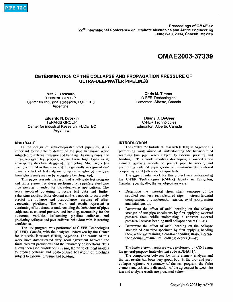
In Figure 1, a typical amplitude distribution is represented as a function of the axial position along the pipe.
0,80
0.70
060
=~ 0.50
~ o.40
Mode
~:12 i111
1110
O8
~7 16
0.30 . , : -
113
m2 0.~0
Axial posit ion [ram]
Figure 1. Typical OD Fourier Decomposition of a Pipe Specimen
A few comments can be made about these geometric imperfections:
• The imperfection that controls the value of the buckling pressure is the second mode [2].
• The angular orientation of the second mode at each section has an important influence on the collapse pressure. When the ellipse that characterizes the second
mode is rotated from one section to the next, the collapse pressure is higher than for the case of aligned ellipses [2].
The value of that second mode is quite different (lower) from the ovality measured with a standard API ovalimeter [3].
Wall thickness was measured at a number of points evenly distributed on the sample external surface using manual ultrasonic gauges. A typical wall thickness distribution is shown in Figure 2.
,,Son
Generabix
Figure 2. Typical Wall Thickness Distribution of a Pipe Specimen
Table 1 summarizes the geometrical measurements taken for each specimen.
Table 1. Test Specimens
• tO qD
.o 2 2
Z •
Z E m m A • ~ E 2 E=
a- ¢n <
1 7782 353.1 22.07 1 7784 352.9 22.04 2 7871 353.0 21.84 3 7549 325.0 18.37 3 7673 325.0 18.32 4 7548 325.2 18.18 5 7550 323.4 21.17 5 7672 323.7 21.11 6 7547 323.8 21.14
t l l >
o E E'8
= ,, '~ o = 0 ~ ~ ~-
16.0 0.39 0.053 Collaps~ 16.0 0.40 0.050 P-->B 16.2 0.41 0.069 P-->B 17.7 0.20 0.097 Collapse 17.7 0.17 0.067 P-->B 17.9 0.21 0 .051 P-~B 15.3 0.23 0.066 Collapse 15.3 0.25 0.088 P-~B 15.3 0.20 0 .081 B-->P
* Equations for Ovality and Eccentncity Presented in the Nomenclature Section.
Material Property Tests
Coupon Tests 70 tension and compression tests were performed on pipe
coupons taken from the circumferential and axial directions. All tension and compression coupon tests were conducted using C-FER's material testing machine shown in Figure 3.
2 Copyright © 2003 by ASME

Figure 3. Testing Coupons at C-FER
The grip assembly used in the set-up is designed to prevent the ends of the specimen from rotating. Complete specimen end fixity was desired in order to prevent specimen buckling and to achieve 1% strain in the compression tests.
Measured yield strengths, based on 0.5% strain, ranged from 427 to 551 MPa for the tensile tests and 452 to 648 MPa for the compression tests. Table 2 summarizes the hoop compressive yield strengths for each specimen. Figure 4 shows some sample stress strain curves from Specimen 7549.
Table 2. Specimen Hoop Compressive Yield Strengths
.Q
z E
E ca
1 7782
1 7784 2 7783
2 7871 3 7549
4 7548
5 755o 6 7547
c5
, < > -
589
583
565
595
536
499
491
493
6O0 I I I I
[ :'
=200 i ; 100 / 1
0 r i I p
0.00 0.50 1.00
, Longitudinal Tension . . . . . . . Longitudinal Compression
Transverse Tension - - - -Transverse Compression
r
1.50 2.00 2.50 3.00
S t r a i n (%)
Figure 4. Stress Strain Curves for Specimen 7549
Ring SDlittinq T e s t s Six ring splitting tests were conducted to determine pipe
cross-sectional circumferential residual stresses. A cold saw cutter was used to cut the pipe ring samples for the tests. This cutter was used instead of a flame cutter to ensure the material properties of the pipe specimens were not altered by any thermal effects, thereby ensuring accurate ring openings occurred. The results of these tests were used to estimate cross- sectional circumferential residual stresses.
Ring splitting tests were performed for each supplied pipe to measure the opening displacement of the ring sections, from which residual stress estimations were made. Residual stresses were calculated assuming a linear-elastic bending stress distribution through the wall thickness.
The results of the nng splitting tests are shown in Table 3.
Table 3. Ring Splitting Test Results
.D
E z at
a .
1 2 3 4 5 6
E z
E
t/)
7782 7783 7549 7548 7550 7547
o o o o tu~
2.45 2.68 0.00 0.00 37 2.85 2.82 0.00 0.00 41 13.41 13.09 1.29 -1.37 177 11.28 11.43 1.31 -1.32 152 5.78 5.67 0.00 0.00 91 4.15 3.99 0.00 0.00 65
Ful l -scale T e s t s C-FER's Deepwater Experimental Chamber was used for
the full-scale tests [4]. The chamber, shown in Figure 5, has a tested pressure capacity of 62 MPa, with an inside diameter of 1.22 m and an overall inside length of 10.3 m.
Figure 5. C-FER's Deepwater Experimental Chamber
3 Copyright © 2003 by ASME
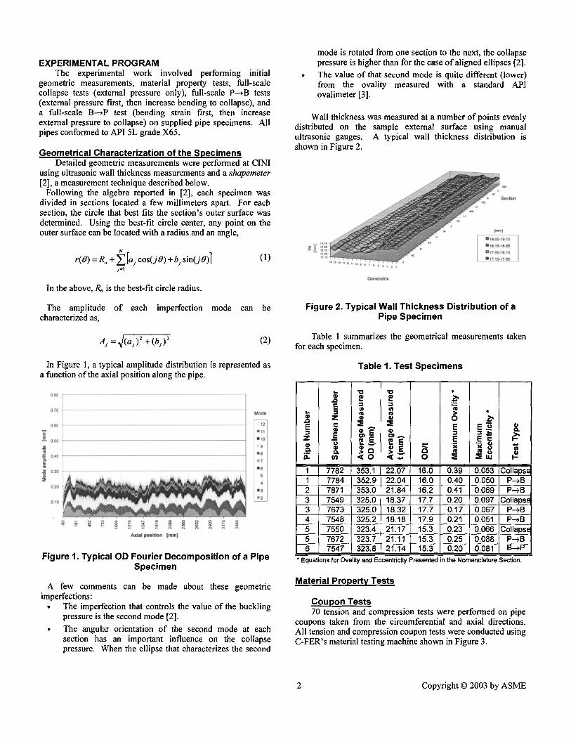
Collapse and Buckle Propagation Tests Three collapse and buckle propagation tests were
conducted. Two of the collapse tests required pressures in excess of 62 MPa. To achieve higher pressures, a secondary pressure vessel was used inside of the Deepwater Experimental Chamber, allowing pressures up to 80 MPa. Figure 6 illustrates this arrangement. After initial collapse, continuing to pump water into the pressure vessel propagated the buckle. The propagation pressure for the three tests averaged 24% of collapse pressure.
Figure 6. Pipe-in-pipe Set-up for High Pressure Tests
Measurements taken during the test included primary and secondary chamber pressures, specimen internal pressure (which was maintained near atmospheric pressure), the volume of water being pumped into the chamber, the volume of water coming out of the specimen, and the date and time.
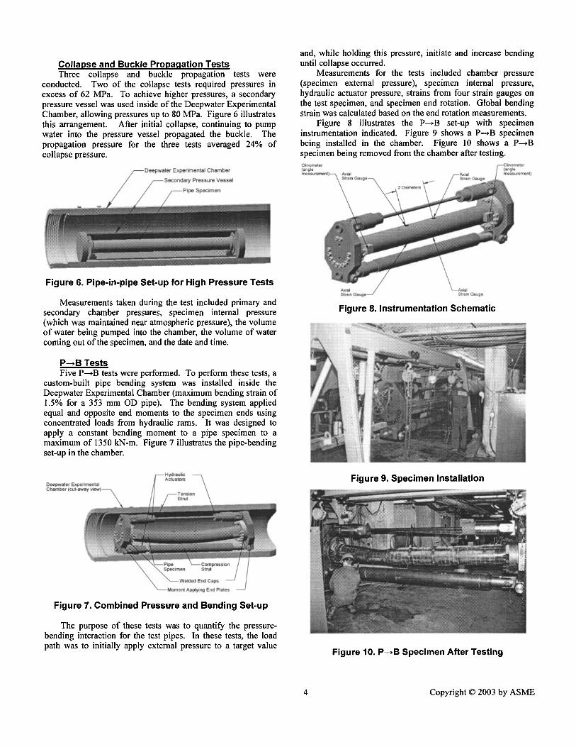
P--,B Tests Five P--~B tests were performed. To perform these tests, a
custom-built pipe bending system was installed inside the Deepwater Experimental Chamber (maximum bending strain of 1.5% for a 353 mm OD pipe). The bending system applied equal and opposite end moments to the specimen ends using concentrated loads from hydraulic rams. It was designed to apply a constant bending moment to a pipe specimen to a maximum of 1350 kN-m. Figure 7 illustrates the pipe-bending set-up in the chamber.
. . . . . . . . . . . . VV~3,HU . . . . . . . . . .
Figure 7. Combined Pressure and Bending Set-up
The purpose of these tests was to quantify the pressure- bending interaction for the test pipes. In these tests, the load path was to initially apply external pressure to a target value
and, while holding this pressure, initiate and increase bending until collapse occurred.
Measurements for the tests included chamber pressure (specimen external pressure), specimen internal pressure, hydraulic actuator pressure, strains from four strain gauges on the test specimen, and specimen end rotation. Global bending strain was calculated based on the end rotation measurements.
Figure 8 illustrates the P--.B set-up with specimen instrumentation indicated. Figure 9 shows a P-*B specimen being installed in the chamber. Figure 10 shows a P---~B specimen being removed from the chamber atter testing.
C l i n o m e t e r ( a n g l e m e a s u r e m e ~nt)
Figure 8. Instrumentation Schematic
Figure 9. Specimen Installation
Figure 10. P--~B Specimen After Testing
4 Copyright © 2003 by ASME
Collapse of many of the specimens was characterized by an audible "bong", a sudden decrease in external pressure and a sudden increase in specimen internal pressure.
B-->P Test A single B--*P test was performed. The purpose of this test
was to quantify the effect of load path on the critical pressure versus bending strain relationship. The load path for this test was to initially apply bending to a target strain level and, while holding the strain constant, increase external pressure until collapse occurred.
Test set-up and measurements for this test were identical to the P--~B tests described in the previous section.
Moment-strain plots for each of the bend tests are shown in Figure 11. The relation between increasing applied bending and decreasing collapse pressure agrees with the same tendency reported in [5] as a result of finite element simulations of B--~P tests.
1 0 0 0 . . ~ -'Z'-" " " " ' ~' . . ~
9OO
6oo 500
=E == 40o
2OO
IO0
0 , ,
0 0.2 0.4
. . . . . . . Specimen 7784 - Pressure + Bend
Specimen 7871 - Pressure + Bend
. . . . Specimen 7673 - Pressure + Bend -
Specimen 7548 - Pressure + Bend
. . . . Specimen 7672 - Pressure + Bend
.......... Specimen 7547 - Bend + Pressure
I I r t 0.6 0.8 1 1.2 1.4 1.6
S t ra in (o~
Figure 11. Bending M o m e n t - S t r a i n Plots
For all tests, the slope of the elastic portion of the bending moment-strain curve matched closely with elastic solid mechanics predictions. The strain gauges agreed well with the overall strain calculated based on the end rotation during the elastic portion of the bending. As expected, strain localization caused significant variation in the strain gauge measurements during the plastic portion of the test. For this reason, the angle measurements are reported as the best measure of global strain.
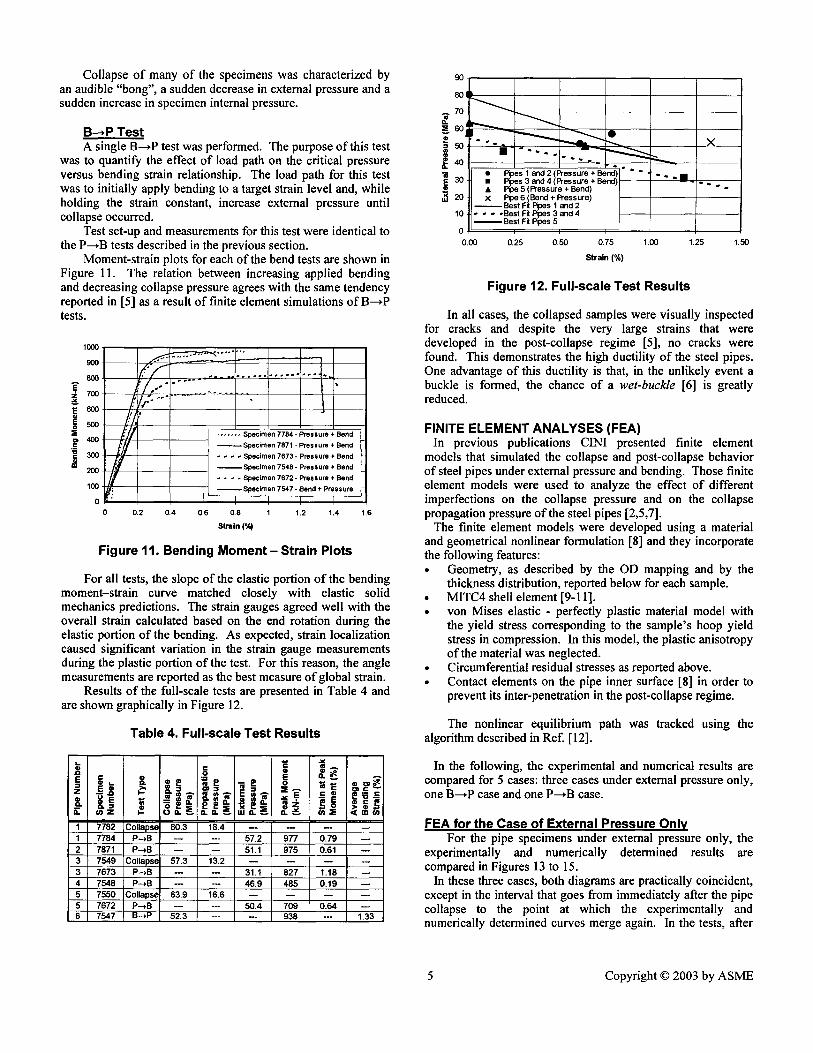
Results of the full-scale tests are presented in Table 4 and are shown graphically in Figure 12.
Table 4. Full-scale Test Results
- # . g ~ m m 1 7 7 8 2 C o l l a p s e 8 0 . 3 18 .4 . . . .
1 7 7 8 4 P ~ B - - - - 5 7 . 2 9 7 7 0 . 7 9 - -
2 7871 P ~ B - - - - 51 .1 9 7 5 0 .61 - -
3 7 5 4 9 C o l l a p s e 5 7 . 3 13.2 . . . .
3 7 6 7 3 P ~ B - - - - 31 .1 8 2 7 1 .18 - -
4 7 5 4 8 P--~B . . . . 4 6 . 9 4 8 5 0 . 1 9
5 7 5 5 0 C o l l a p s e 6 3 . 9 16 .6 . . . .
5 7 6 7 2 P - ~ B . . . . 5 0 . 4 7 0 9 0 . 6 4 - -
6 7 5 4 7 B--~P 5 2 . 3 - - - - 9 3 8 - - 1 .33
90
7 0
60 I ~ 5 0 ' ' - ° _ i 40 ° -
• Pipes 1 and 2 (P ressure + Bend) 30 • Pipes 3 and 4 (P ressure + Band) " ° " I I
• • Pipe 5 (P ressure + Bend) 20 X Pipe 6 (Bend + Pressure)
Best Fit Rpes 1 and 2 1 0 - - - - B e s t F i t F ~ p e s 3 a n d 4
Best Fit Rpes 5 0 I I I I I
0.00 0.25 0 .50 0.75 1.00 1.25
Strain (%)
1.50
Figure 12. Full-scale Test Results
In all cases, the collapsed samples were visually inspected for cracks and despite the very large strains that were developed in the post-collapse regime [5], no cracks were found. This demonstrates the high ductility of the steel pipes. One advantage of this ductility is that, in the unlikely event a buckle is formed, the chance of a wet-buckle [6] is greatly reduced.
FINITE ELEMENT ANALYSES (FEA) In previous publications C1NI presented finite element
models that simulated the collapse and post-collapse behavior of steel pipes under external pressure and bending. Those finite element models were used to analyze the effect of different imperfections on the collapse pressure and on the collapse propagation pressure of the steel pipes [2,5,7].
The finite element models were developed using a material and geometrical nonlinear formulation [8] and they incorporate the following features: • Geometry, as described by the OD mapping and by the
thickness distribution, reported below for each sample. • MITC4 shell element [9-11]. • von Mises elastic - perfectly plastic material model with
the yield stress corresponding to the sample's hoop yield stress in compression. In this model, the plastic anisotropy of the material was neglected.
• Circumferential residual stresses as reported above. • Contact elements on the pipe inner surface [8] in order to
prevent its inter-penetration in the post-collapse regime.
The nonlinear equilibrium path was tracked using the algorithm described in Ref. [12].
In the following, the experimental and numerical results are compared for 5 cases: three cases under external pressure only, one B---*P case and one P---*B case.
FEA for the Case of External Pressure Only For the pipe specimens under external pressure only, the
experimentally and numerically determined results are compared in Figures 13 to 15.
In these three cases, both diagrams are practically coincident, except in the interval that goes from immediately after the pipe collapse to the point at which the experimentally and numerically determined curves merge again. In the tests, after
5 Copyright © 2003 by ASME
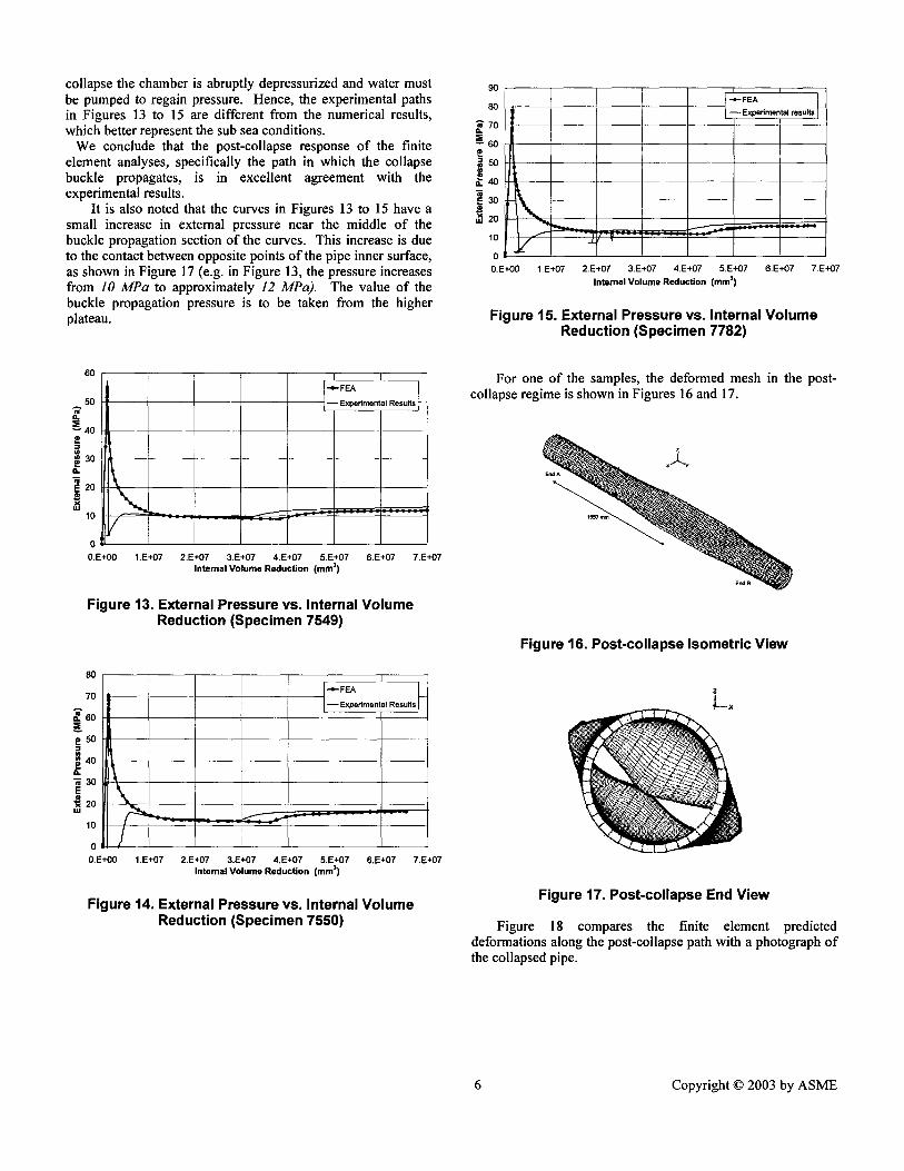
collapse the chamber is abruptly depressurized and water must be pumped to regain pressure. Hence, the experimental paths in Figures 13 to 15 are different from the numerical results, which better represent the sub sea conditions.
We conclude that the post-collapse response of the finite element analyses, specifically the path in which the collapse buckle propagates, is in excellent agreement with the experimental results.
It is also noted that the curves in Figures 13 to 15 have a small increase in external pressure near the middle of the buckle propagation section of the curves. This increase is due to the contact between opposite points of the pipe inner surface, as shown in Figure 17 (e.g. in Figure 13, the pressure increases from 10 MPa to approximately 12 MPa). The value of the buckle propagation pressure is to be taken from the higher plateau.
60
50 m
40
E 30 m E 20
10
80
70 A
so
50
~ 3O E • ~ 20
10
I • -e- FEA /
- - Experimenta Resu Is
0 0.E+00 6.E+07 I.E+07 2.E+07 3.E+07 4,E+07 5.E+07
Internal V o l u m e R e d u c t i o n (ram ~) 7.E+07
Figure 13. External Pressure vs. Internal Volume Reduction (Specimen 7549)
I
- - Experimental Results |
o, ~'~ . . . . . . . "~"7"-~ "-~ .....
0.E+00 I.E+07 2.E+07 3.E+07 4.E+07 5.E+07 6.E+07 7.E+07 Internal Volume Reduction (ram s)
Figure 14. External Pressure vs. Internal Volume Reduction (Specimen 7550)
9O
8O
'~ 70 D. :E ~ 6 0 R
EaO
~ 20 10
I -e- FEA I
I - - Experimental results
\ f I 0
0.E+00 1.E+07 2.E+07 3.E+07 4.E+07 5.E+07 6.E+07 7.E+07 Internal Volume Reduction (ram 3)
Figure 15. External Pressure vs. Internal Volume Reduction (Specimen 7782)
For one of the samples, the deformed mesh in the post- collapse regime is shown in Figures 16 and 17.
Figure 16. Post-collapse Isometric View
z
Figure 17. Post-collapse End View
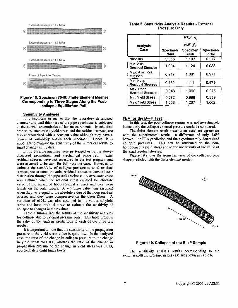
Figure 18 compares the finite element predicted deformations along the post-collapse path with a photograph of the collapsed pipe.
6 Copyright © 2003 by A S M E
®
®
®
®
External Dressure = 12.4 MPa
®
External ioressure = 11.7 MPa
®
External pressure = 11.8 MPa
@
Photo of Pipe After Testing
Figure 18. Specimen 7549; Finite Element Meshes Corresponding to Three Stages Along the Post-
collapse Equilibrium Path
Sensitivity Analyses It is important to realize that the laboratory determined
diameter and wall thickness of the pipe specimens is subjected to the normal uncertainties of lab measurements. Mechanical properties, such as the yield stress and the residual stresses, are also characterized with a constant value although they have a degree of variability within each specimen. Hence, it is important to evaluate the sensitivity of the numerical results to small changes in the data.
Initial baseline analyses were performed using the above- discussed geometrical and mechanical properties. Axial residual stresses were not measured in the test program and were assumed to be zero for this baseline case. However, to estimate the sensitivity of collapse pressure to axial residual stresses, we assumed the axial residual stresses to have a linear distribution through the pipe wall thickness. A maximum value was assumed when the residual stress equaled the absolute value of the measured hoop residual stresses and they were tensile on the outer fibers. A minimum value was assumed when they were equal to the absolute value of the hoop residual stresses and they were compressive on the outer fibers. A variation of ±10% was also assumed in the values of yield stress and hoop residual stress to estimate the sensitivity of collapse to changes in their values.
Table 5 summarizes the results of the sensitivity analyses for collapse due to external pressure only. This table presents the ratio of the analysis predictions to each of the three test results.
It is important to note that the sensitivity of the propagation pressure to the yield stress value is quite low. In the analyzed case, the ratio of the change in collapse pressure to the change in yield stress was 0.1, whereas the ratio of the change in propagation pressure to the change in yield stress was 0.013, approximately eight times lower.
Table 5. Sensitivity Analysis Results - External Pressure Only
Analysis Case Specimen
7549
FEA p~
test Pc
Specimen 7550
Specimen 7782
Baseline 0.966 1.103 0.977 Min. Axial Residual Stresses 1.004 1.124 0.983
Max. Axial Res. stresses 0.917 1.081 0.971
Min. Hoop Residual Stresses 0.982 1.11 0.979
Max. Hoop Residual Stresses 0.948 1.096 0.975
Min. Yield Stress 0.872 0.998 0.889 Max. Yield Stress 1.058 1.207 1.062
FEA for the B--,P Test In this test, the post-collapse regime was not investigated;
hence, only the collapse external pressure could be compared. The finite element result presents an excellent agreement
with the experimental result: a difference of only 3.6% between the FEA prediction and the experimentally determined collapse pressures. This can be attributed to the non- homogeneous yield stress and to the uncertainty of the value of the axial residual stresses.
Figure 19 shows the isometric view of the collapsed pipe shape predicted with the finite element model.
End B
Figure 19. Collapse of the B--~P Sample
The sensitivity analysis results corresponding to the external collapse pressure in this case are shown in Table 6.
7 Copyright © 2003 by ASME
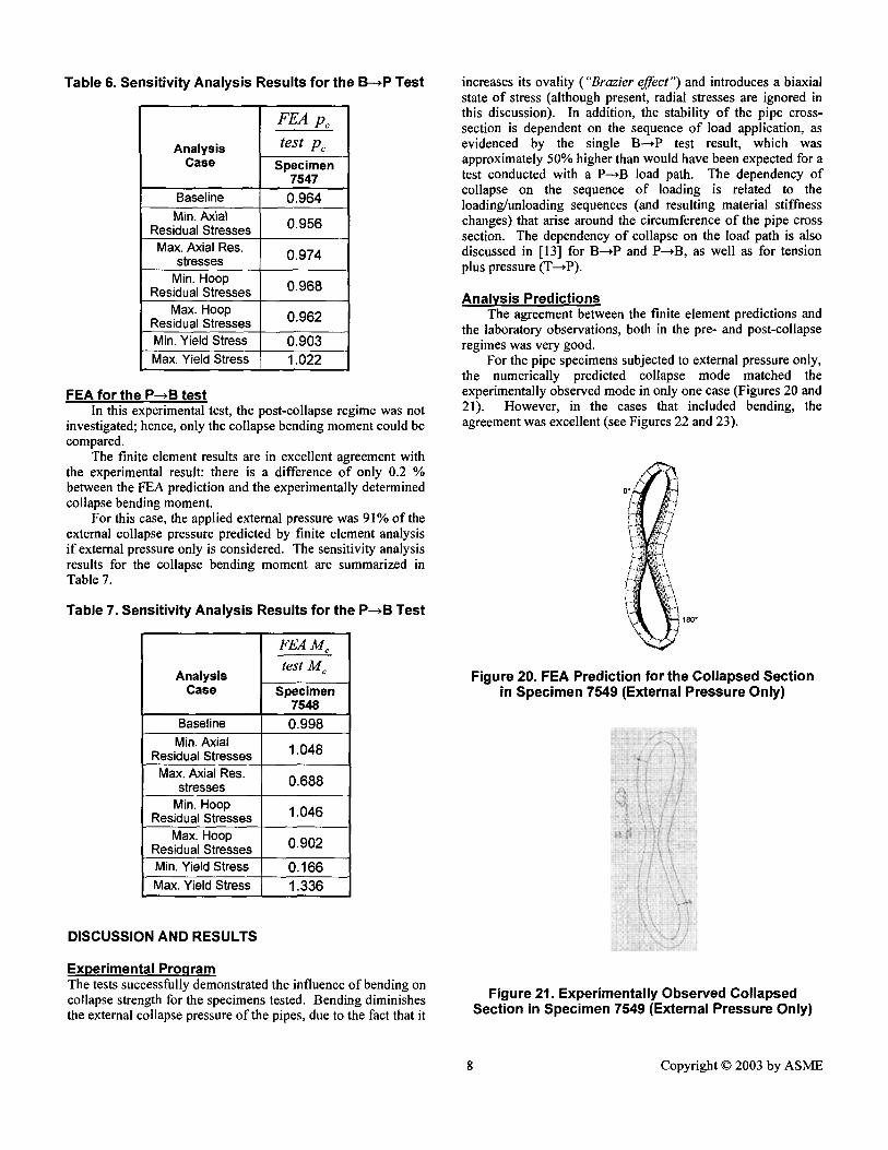
Table 6. Sensitivity Analysis Results for the B-.P Test
Analysis Case
FEA Pc
test Pc
Specimen 7547
Baseline 0.964 Min. Axial
Residual Stresses 0.956 Max. Axial Res.
stresses 0.974
Min. Hoop Residual Stresses 0.968
Max. Hoop Residual Stresses 0.962 Min. Yield Stress 0.903 Max. Yield Stress 1.022
FEA for the P--~B test In this experimental test, the post-collapse regime was not
investigated; hence, only the collapse bending moment could be compared.
The finite element results are in excellent agreement with the experimental result: there is a difference of only 0.2 % between the FEA prediction and the experimentally determined collapse bending moment.
For this case, the applied external pressure was 91% of the external collapse pressure predicted by finite element analysis if external pressure only is considered. The sensitivity analysis results for the collapse bending moment are summarized in Table 7.
Table 7. Sensitivity Analysis Results for the P--~B Test
Analysis Case
F E A M
test M c
Baseline Min. Axial
Residual Stresses 1.048 Max. Axial Res.
stresses 0.688 Min. Hoop
Residual Stresses 1.046 Max. Hoop
Residual Stresses 0.902 Min. Yield Stress 0.166 Max. Yield Stress 1.336
Specimen 7548 0.998
DISCUSSION AND RESULTS
Experimental Program The tests successfully demonstrated the influence of bending on collapse strength for the specimens tested. Bending diminishes the external collapse pressure of the pipes, due to the fact that it
increases its ovality ("Brazier effect") and introduces a biaxial state of stress (although present, radial stresses are ignored in this discussion). In addition, the stability of the pipe cross- section is dependent on the sequence of load application, as evidenced by the single B---~P test result, which was approximately 50% higher than would have been expected for a test conducted with a P--,B load path. The dependency of collapse on the sequence of loading is related to the loading/unloading sequences (and resulting material stiffness changes) that arise around the circumference of the pipe cross section. The dependency of collapse on the load path is also discussed in [13] for B---~P and P--~B, as well as for tension plus pressure (T---~P).
Analysis Predictions The agreement between the finite element predictions and
the laboratory observations, both in the pre- and post-collapse regimes was very good.
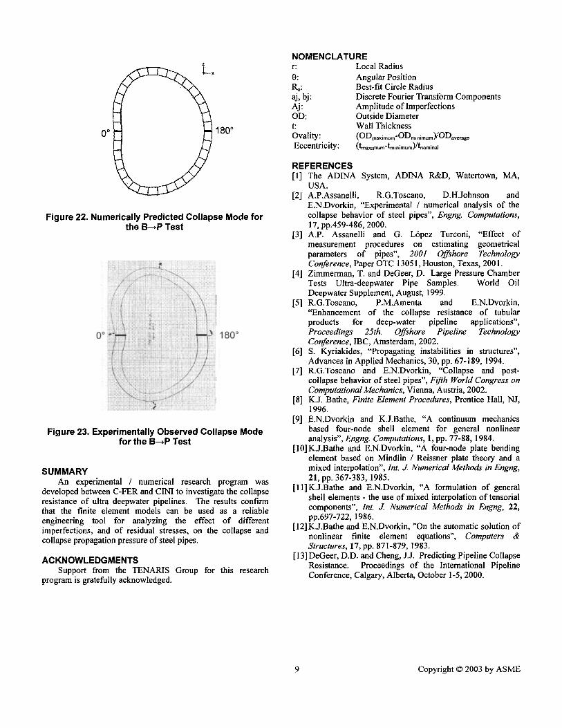
For the pipe specimens subjected to external pressure only, the numerically predicted collapse mode matched the experimentally observed mode in only one case (Figures 20 and 21). However, in the cases that included bending, the agreement was excellent (see Figures 22 and 23).
J
180"
Figure 20. FEA Prediction for the Collapsed Section in Specimen 7549 (External Pressure Only)
Figure 21. Experimentally Observed Collapsed Section in Specimen 7549 (External Pressure Only)
8 Copyright © 2003 by ASME
z
L ~
0 o 180 °
Figure 22. Numerically Predicted Collapse Mode for the B~P Test
o 1 8 0 °
Figure 23. Experimentally Observed Collapse Mode for the B~P Test
SUMMARY An experimental / numerical research program was
developed between C-FER and CINI to investigate the collapse resistance of ultra deepwater pipelines. The results confirm that the finite element models can be used as a reliable engineering tool for analyzing the effect of different imperfections, and of residual stresses, on the collapse and collapse propagation pressure of steel pipes.
ACKNOWLEDGMENTS Support from the TENARIS Group for this research
program is gratefully acknowledged.
NOMENCLATURE r: 0: Ro: aj, bj: Aj: OD: t: Ovality: Eccentricity:
Local Radius Angular Position Best-fit Circle Radius Discrete Fourier Transform Components Amplitude of Imperfections Outside Diameter Wall Thickness (ODrnaximum-ODminimum)/ODaverage (tmaxiln um-tminimum)/tnominal
REFERENCES [1] The ADINA System, ADINA R&D, Watertown, MA,
USA. [2] A.P.Assanelli, R.G.Toscano, D.H.Johnson and
E.N.Dvorkin, "Experimental / numerical analysis of the collapse behavior of steel pipes", Engng. Computations, 17, pp.459-486, 2000.
[3] A.P. Assanelli and G. Lrpez Turconi, "Effect of measurement procedures on estimating geometrical parameters of pipes", 2001 Of~hore Technology Conference, Paper OTC 13051, Houston, Texas, 2001.
[4] Zimmerman, T. and DeGeer, D. Large Pressure Chamber Tests Ultra-deepwater Pipe Samples. Wodd Oil Deepwater Supplement, August, 1999.
[5] R.G.Toscano, P.M.Amenta and E.N.Dvorkin, "Enhancement of the collapse resistance of tubular products for deep-water pipeline applications", Proceedings 25th . Of~hore Pipeline Technology Conference, IBC, Amsterdam, 2002.
[6] S. Kyriakides, "Propagating instabilities in structures", Advances in Applied Mechanics, 30, pp. 67-189, 1994.
[7] R.G.Toscano and E.N.Dvorkin, "Collapse and post- collapse behavior of steel pipes", Fifth World Congress on Computational Mechanics, Vienna, Austria, 2002.
[8] K.J. Bathe, Finite Element Procedures, Prentice Hall, NJ, 1996.
[9] E.N.Dvorkin and K.J.Bathe, "A continuum mechanics based four-node shell element for general nonlinear analysis", Engng. Computations, 1, pp. 77-88, 1984.
[10]K.J.Bathe and E.N.Dvorkin, "A four-node plate bending element based on Mindlin / Reissner plate theory and a mixed interpolation", Int. J. Numerical Methods in Engng, 21, pp. 367-383, 1985.
[l l] K.J.Bathe and E.N.Dvorkin, "A formulation of general shell elements - the use of mixed interpolation of tensorial components", Int. J. Numerical Methods in Engng, 22, pp.697-722, 1986.
[12] K.J.Bathe and E.N.Dvorkin, "On the automatic solution of nonlinear finite element equations", Computers & Structures, 17, pp. 871-879, 1983.
[13] DeGeer, D.D. and Cheng, J.J. Predicting Pipeline Collapse Resistance. Proceedings of the International Pipeline Conference, Calgary, Alberta, October 1-5, 2000.
9 Copyright © 2003 by ASME