Embed Size (px)
Citation preview
Interfacial Phenomena and Heat Transfer, 1 (1): 29–49 (2013)
DETERMINATION OF APPARENT CONTACT ANGLEAND SHAPE OF A STATIC PENDANT DROP ON APHYSICALLY TEXTURED INCLINED SURFACE
Gaurav Bhutani, K. Muralidhar, & Sameer Khandekar∗
Department of Mechanical Engineering, Indian Institute of Technology Kanpur, Kanpur 208016,India
∗Address all correspondence to Sameer Khandekar, E-mail: [email protected]
Estimating the apparent contact angle under equilibrium conditions is critical for the understanding of several engi-neering processes. Some examples are dropwise condensation, digital microfluidics, and material deposition schemes.Often, there is considerable uncertainty in the experimental estimation of the contact angle. In this work, we discuss thecontact angles and shapes of pendant drops on physically textured inclined surfaces. Two methodologies to determinethe apparent contact angles have been employed. In one approach these are obtained from drawing tangents at contactpoints of micro-droplets in optical images using digital image processing. In the second method, the three-dimensional(3D) Young–Laplace equation is numerically solved using the open-source software, Surface Evolver, by minimizingthe sum of the potential and surface energies of the pendant droplet. A section of the numerically obtained 3D dropletshape is then fitted to the experimentally obtained two-dimensional profile using an inverse method. Advancing andreceding angles of the imaged drop are calculated by minimizing the error between the numerical and experimentaldrop shapes, providing good estimates of these angles. In addition, the complete 3D droplet shape is also obtained. Theoverall methodology presented herein is generic, although the experiments have been conducted with glycerin as theworking fluid. The role of surface roughness, plate inclination, and drop volume on the advancing and receding anglesof a pendant drop are discussed. On inclined surfaces, the three-phase contact line does not remain pinned and its shapeis not circular. The receding angle progressively diminishes with inclination while the advancing angle remains nearlyconstant.
KEY WORDS: pendant drop, apparent contact angle, drop profile, advancing and receding angles, SurfaceEvolver, inverse technique, surface roughness, surface inclination
1. INTRODUCTION
Surface energy–induced drop movement in microfluidic systems is of importance in microscale thermophysical de-vices, biological microelectromechanical systems (bio-MEMS), and lab-on-chip applications. Texturing and pattern-ing are physical methods of altering contact angles locally and can be utilized in the design of surface energy gradi-ents. Physical texturing is preferred over chemical techniques because chemical coatings tend to wear off by viscousstresses. In the search for better surfaces, data on contact angles of pendant drops and their sensitivity to substrateinclination and texture are often required. The present study is concerned with developing a formal approach thatextracts contact angles from photographic images of drops. Knowledge of the apparent contact angle (referred to asthe contact angle in subsequent discussions) and the shape of a pendant drop formed on a substrate are also importantin understanding processes such as dropwise condensation, drug delivery, microscale thermophysical engineering,and adhesive technology, to name a few. Equilibrium contact angles, in turn, carry information on surface properties,including wettability and surface energy. An important application requiring detailed knowledge of contact angles aswell as the three-dimensional (3D) shapes is the process of vapor condensation as a collection of drops (Sikarwar et al.,2011), particularly of low-conductivity liquids. Dropwise condensation is preferred over the filmwise mode owing toits high heat transfer coefficient and control of the condensation rate, particularly on inclined surfaces (Carey, 1992).
2169–2785/13/$35.00 c© 2013 by Begell House, Inc. 29
30 Bhutani, Muralidhar, & Khandekar
NOMENCLATURE
B ratio of excess pressure inside the drop ζ coordinate along the symmetry axisto surface tension at liquid-gas interface (m−1) in an axisymmetric drop
Bo Bond number (= ρgD2 sin α/γ) θ contact angle (◦)D base diameter of a horizontal drop (m) θadv advancing angle (◦)D′ base diameter of a drop on an inclined θE Young’s contact angle (◦)
plate (m) θrec receding angle (◦)d maximum drop height in thez direction (m) θmin minimum contact angle ofg acceleration due to gravity (m/s2) a three-dimensional drop (◦)R radial distance measured from the center θmax maximum contact angle
of a drop cap (m) of a three-dimensional drop (◦)r root-mean-square roughness of a surface (m) θo horizontal drop contact angle (◦)r′ Wenzel’s roughness parameter (= actual surface θ∗ Wenzel’s contact angle (◦)
area/projected surface area) κm mean curvature of the liquid–airVD volume of the drop (m3) interface (m−1)z vertical coordinate taken as positive µ liquid viscosity (Pa-s)
in the downward direction ρf density of the liquid (kg/m3)σ axis perpendicular to the symmetry axis
Greek Symbols in an axisymmetric dropα substrate inclination angle (◦) φ azimuthal angle measured along theβ polar angle (◦) three-phase contact line (◦)γ surface tension (N/m) ψ angle made by the tangent on the surface∆p excess pressure inside the drop (Pa) of an axisymmetric drop (◦)
Here, knowledge of the three-phase contact angle distribution going around the circumference of the condensed liquiddroplet is essential to accurately determine the transport rates. Contact angles also govern the interaction of interfacialand body forces acting on sessile and pendant drops. The molecular forces at the three-phase contact line manifest atthe macroscopic level as the contact angle and affect steady as well as unsteady transport phenomena.
The physicochemical interaction of liquids on solid surfaces is an active subject of research and has been exten-sively pursued (Fox and Zisman, 1950; Tuteja et al., 2008; Ajaev et al., 2010; Style and Dyfresne, 2012). Contactangles of various solid–liquid combinations have been reported in the literature. Much of these data are applicable tosessile drops owing to the ease of experimentation. In contrast, pendant drops are difficult to deal with in experiments,especially when the droplet volumes are of the order of microliters. In addition, when the surface on which the pen-dant drop is deposited is inclined with respect to the horizontal, the advancing angle will be greater than the recedingangle. These angles are a function of plate inclination. Overall, the drop is deformed and becomes non-axisymmetric.Although there is an abundance of data on contact angles, there exists a clear gap in the knowledge of contact anglesof pendant drops on inclined surfaces. Brown et al. (1980), El Sherbini and Jacobi (2004), and Annapragada et al.(2012) have discussed the effect of plate inclination on the advancing and receding angles of sessile drops. Recedingcontact angles of sliding drops have also been discussed by Winkels et al. (2011). Cheng et al. (1990) performedexperiments on pendant axisymmetric glycerin and water drops to measure the contact angles. On inclined surfaces,the advancing contact angle is different from the receding contact angle and the difference is termed the contact anglehysteresis (CAH).
Factors such as the physical morphology, surface roughness, chemical texture, presence of impurities, non-homogeneity, anisotropic surface characteristics, substrate inclination, and presence of external body and surfaceforces affect the equilibrium contact angles of liquid droplets on solid surfaces. Temperature is an important parame-ter because thermophysical properties depend on it.
Interfacial Phenomena and Heat Transfer
Determination of Apparent Contact Angle 31
One method of altering the wettability of a substrate is to treat it chemically by grafting or adsorbing specialpromoter molecules with wetting characteristics of their own. This effect of chemical texturing has been previouslystudied (Wolfram and Faust, 1978; Lee, 1999; Berthier, 2008; Bhushan and Jung, 2011). Chemically textured sur-faces have been synthesized to control surface energy gradients and obtain very large contact angles and low CAH(Bico et al., 1999). Such super-hydrophobic surfaces have a contact angle greater than 150◦ and CAH less than 10◦.Furthermore, substrates with designed surface energy gradients can also be formed, which are useful in controllingthe flow of drops at low or no plate inclination, and this is an area of extensive research (Chaudhury and Whitesides,1992; Shastry et al., 2006). In applications where the liquid forming the droplets is highly corrosive—for example, inmetal vapor condensation processes—the chemically textured surface usually has a short lifespan. The promoter layergets leeched away by the condensing liquid droplets, thereby deteriorating the substrate and altering the contact angle.This shortcoming has created a need to alter the surface properties by introducing roughness or through alteration ofthe physical morphology of the substrate, which can be specifically micro- or nano-patterned or statistically rough(Barthlott and Neinhuis, 1997; Quere, 2002; Abdelsalam et al., 2005; Bhushan and Jung, 2011). The lotus leaf is anaturally rough surface with a hierarchical physical morphology and has been characterized by many authors, includ-ing Barthlott and Neinhuis (1997), Bico et al. (1999), and Bhushan and Jung (2011). Depending on the morphologyand the resulting surface energy distribution, a droplet can sit on a solid surface in two distinct configurations. It issaid to be in a Wenzel state when it is conformal with the topography, and Wenzel’s equation can be used to computethe contact angle (Wenzel, 1936; Berthier, 2008). The other is the Fakir state (Cassie and Baxter, 1944) where thedrop only touches the peaks of the physical protrusions present on the surface.
Besides measuring the contact angle at the base of a drop, it is also important to obtain the shape of the three-phasecontact line; i.e., the footprint of the drop on the substrate. The contact line is actually in quasi-static equilibrium andits shape changes with the plate inclination (Berejnov and Thorne, 2007). In earlier studies, Wolfram and Faust (1978)and Brown et al. (1980) assumed the contact line was circular for a static drop and pinned everywhere for horizontaland inclined plate configurations. Extrand and Kumagai (1995) measured the aspect ratios of the base contours inwater and ethylene glycol drops on polymers. Kalinin et al. (2008) forced the contact line of sessile drops to remainpinned with the inclination by placing them inside photolithographic micro-patterned rings. El Sherbini and Jacobi(2004) showed that the three-phase contact line for a static drop does change with the plate inclination and they fittedthe base contour by two ellipses sharing the minor axis. Much of the work reported on the contact line shape involvessessile drops. The present study examines the contact lines of pendant drops on horizontal and inclined surfaces.
Analytical and numerical techniques have been used to predict the drop shapes in two and three dimensions.Brown et al. (1980) used the finite-element method (FEM) to determine the 3D shapes of static drops on inclinedplates with an assumption of a circular wetted area. Rio and Neumann (1997) fitted numerical shapes to experimentaldrop profiles to compute the contact angles and interfacial tensions. The Young–Laplace equation was solved foraxisymmetric sessile and pendant drops and the entire drop shape fitted to the experimental measurement. Dingleet al. (2005) used a similar fitting technique to determine the interfacial tension values of axisymmetric drops. Iliev(1995) and Liao et al. (2009) used an iterative method to minimize the overall energy of the system to predict theshapes of sessile drops on horizontal and inclined surfaces. Adamiak (2006) obtained the axisymmetric shape of aconducting liquid drop placed on a hydrophobic dielectric surface with an external electric field. A finite-differencemethod was used to simultaneously solve the Poisson equation for the electric field and the Young–Laplace equationfor the drop shape. The wettability of the system was increased by applying an electric potential difference betweenthe droplet and the counter-electrode. The contact angle was seen to follow the Lippman–Young equation (Mugele andBarrett, 2005; Adamiak, 2006; Berthier, 2008). Pozrikidis (2009) developed a parametric route to numerically solvethe Young–Laplace equation and obtained the shapes of axisymmetric sessile and pendant drops. This method hasbeen used to validate the simulations of the present study of a horizontal surface. Santos and White (2011) used theopen-source software,Surface Evolver(http://www.susqu.edu/brakke/evolver/evolver.html), to simulate the shapes ofnon-axisymmetric sessile drops. Annapragada et al. (2012) developed a volume-of-fluid (VOF) continuous-surface-force (CSF) model to predict the shapes of sessile droplets under gravity for various substrate inclinations.
In the present study, pendant drops have been imaged for various plate inclinations, substrate roughness, and dropvolumes to obtain their equilibrium advancing and receding angles. Glycerin was chosen as the working fluid due toits low vapor pressure and high viscosity. Aluminum and copper surfaces of varying average roughness have been
Volume 1, Number 1, 2013
32 Bhutani, Muralidhar, & Khandekar
used as the substrate materials. The apparent contact angles have been estimated using two methods. In Method 1,digital image processing of experimentally obtained images by the tangent method was used. In Method 2, an inversemethod was employed that numerically solves the Young–Laplace equation using a variational approach withSurfaceEvolver. Method 2 also yields 3D drop shapes on inclined surfaces. In Method 2, the 3D shape determined numericallyis selectively fitted to the experimental drop shape to obtain the contact angles. This approach is similar to that of Rioand Neumann (1997), except that the advancing and receding angles of non-axisymmetric pendant drops obtained byan inverse technique as well as their base shapes are reported in the present study.
2. EXPERIMENTAL APPARATUS AND PROCEDURE
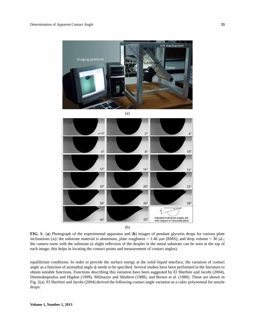
The randomly distributed isotropic roughness of a surface is characterized by its root-mean-square (RMS) value.Three such surfaces with RMS roughness values of around 0.5, 1.5, and 4.0µm were obtained on aluminum andcopper substrates by the wet lapping process. A contact angle measurement goniometric apparatus, developed as partof this work, was used to image the pendant drops on these inclined, randomly textured surfaces. The apparatus [seeFig. 1(a)] can precisely tilt the substrate plate in steps of 1◦ image the pendant drop from a direction normal to thevertical plane of the tilt; namely, the plane of symmetry of the drop over a range of inclinations (0–45◦). Microlitersyringes (100± 2 and 50± 1 µL) were used to deposit liquid pendant drops on the underside of the substrates,with sizes ranging from 5 to 30µL. The working fluid was glycerin; with densityρ = 1260 kg/m3, surface tensionγ = 63.4 mN/m, and dynamic viscosityµ = 1.069 Pa-s. Glycerin has low volatility and high viscosity, which helpsthe drop stabilize in a short time period. In addition, results are presented in terms of the Bond number, which enablesgeneralization of the measured data for other liquids. During the experiments, the room temperature was maintainedat 20± 1◦C. A high-resolution progressive scan charge-coupled device camera (Basler A202k: pixel resolution:1024× 1024), fitted with a macro-lens, was used to image drops without any wide-angle distortion, with each pixelrepresenting about 6µm. A dual-channel frame grabber card was used to grab frames from the camera to be storedin a computer hard drive. Post-processing of the droplet images was performed by programs written inWiT Platform(Teledyne-Dalsa).MATLABprograms extracted the contact angles and drop profiles from the raw images. A pixel-wise scanning algorithm extracted the overall drop profile. The corner pixel was joined to a neighboring pixel to forma tangent. The contact angles have been reported for the eighth neighbor in this study. The angle between this tangentand the horizontal form the basis of the tangent method. To overcome subjectivity in the tangent measurement, animproved inverse technique has been used and is discussed in Sec. 3.2. The drop volume, surface inclination, substrateroughness, and substrate material are the four parameters that were varied in the experiments. Figure 1(b) shows acollection of pendant drop images of a 30µL glycerin drop on an aluminum surface of 1.46µm roughness. Changesin the drop shape and contact angles with increasing plate inclination can be clearly seen in Fig. 1(b).
3. NUMERICAL DETERMINATION OF DROPLET SHAPES
The shape of a static drop supported on a solid surface is governed by the Young–Laplace equation, which balancesthe weight, surface tension, and internal pressure. For two-dimensional (2D) drops, the Young–Laplace equation canbe solved using the approach suggested by Pozrikidis (2009). The Young–Laplace equation for 3D axisymmetricdrops can be represented using two coordinates, and the solution methodology is presented in Appendix 1. In threedimensions, the equation is rather difficult to solve for non-symmetric cases and alternative approaches are preferred(see Appendix 2). A variational approach was used in the present work to compute the 3D drop shape, wherein theoverall energy of the drop (the sum of the potential and interfacial energies) was successively minimized to attain thefinal equilibrium shape of the static droplet on the substrate. This step was achieved usingSurface Evolver(Brakke,1992). Complete information on the 3D shape can be extracted from the minimum energy drop configuration.
3.1 Numerical Solution
This section outlines the numerical method used to obtain the shapes of the pendant drops. To initiate the solution, animaginary cube of liquid of a given volume is taken and its overall energy is minimized to derive the drop shape under
Interfacial Phenomena and Heat Transfer
Determination of Apparent Contact Angle 33
(a)
(b)
FIG. 1: (a) Photograph of the experimental apparatus and (b) images of pendant glycerin drops for various plateinclinations (α): the substrate material is aluminum, plate roughness = 1.46µm (RMS), and drop volume = 30µL;the camera turns with the substrate (a slight reflection of the droplet in the metal substrate can be seen at the top ofeach image; this helps in locating the contact points and measurement of contact angles).
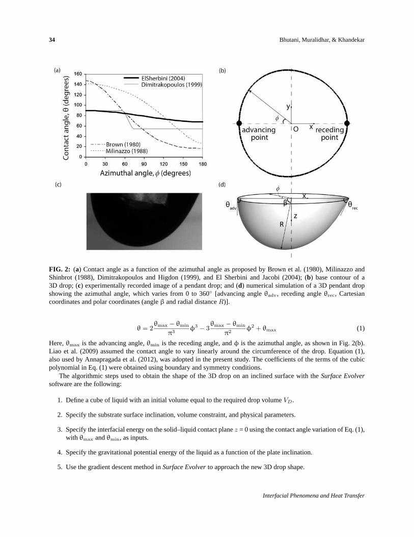
equilibrium conditions. In order to provide the surface energy at the solid–liquid interface, the variation of contactangle as a function of azimuthal angleφ needs to be specified. Several studies have been performed in the literature toobtain suitable functions. Functions describing this variation have been suggested by El Sherbini and Jacobi (2004),Dimitrakopoulos and Higdon (1999), Milinazzo and Shinbrot (1988), and Brown et al. (1980). These are shown inFig. 2(a). El Sherbini and Jacobi (2004) derived the following contact angle variation as a cubic polynomial for sessiledrops:
Volume 1, Number 1, 2013
34 Bhutani, Muralidhar, & Khandekar
FIG. 2: (a) Contact angle as a function of the azimuthal angle as proposed by Brown et al. (1980), Milinazzo andShinbrot (1988), Dimitrakopoulos and Higdon (1999), and El Sherbini and Jacobi (2004); (b) base contour of a3D drop; (c) experimentally recorded image of a pendant drop; and (d) numerical simulation of a 3D pendant dropshowing the azimuthal angle, which varies from 0 to 360◦ [advancing angleθadv, receding angleθrec, Cartesiancoordinates and polar coordinates (angleβ and radial distanceR)].
θ = 2θmax − θmin
π3φ3 − 3
θmax − θmin
π2φ2 + θmax (1)
Here,θmax is the advancing angle,θmin is the receding angle, andφ is the azimuthal angle, as shown in Fig. 2(b).Liao et al. (2009) assumed the contact angle to vary linearly around the circumference of the drop. Equation (1),also used by Annapragada et al. (2012), was adopted in the present study. The coefficients of the terms of the cubicpolynomial in Eq. (1) were obtained using boundary and symmetry conditions.
The algorithmic steps used to obtain the shape of the 3D drop on an inclined surface with theSurface Evolversoftware are the following:
1. Define a cube of liquid with an initial volume equal to the required drop volumeVD.
2. Specify the substrate surface inclination, volume constraint, and physical parameters.
3. Specify the interfacial energy on the solid–liquid contact planez = 0 using the contact angle variation of Eq. (1),with θmax andθmin, as inputs.
4. Specify the gravitational potential energy of the liquid as a function of the plate inclination.
5. Use the gradient descent method inSurface Evolverto approach the new 3D drop shape.
Interfacial Phenomena and Heat Transfer
Determination of Apparent Contact Angle 35
6. Correct for the center of the base contour (after each iteration) to calculate azimuthal angleφ within SurfaceEvolver.
7. Repeat Steps 3–6 until the drop shape converges to a minimum energy.
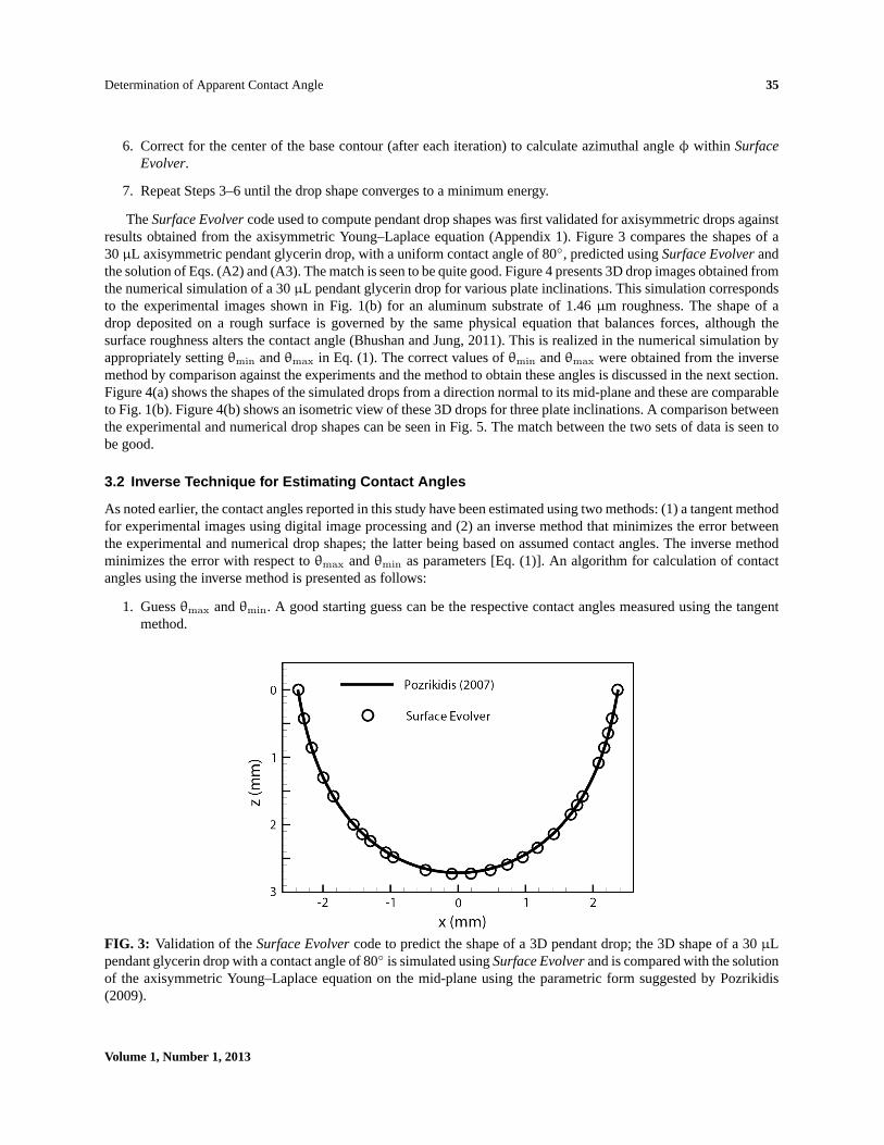
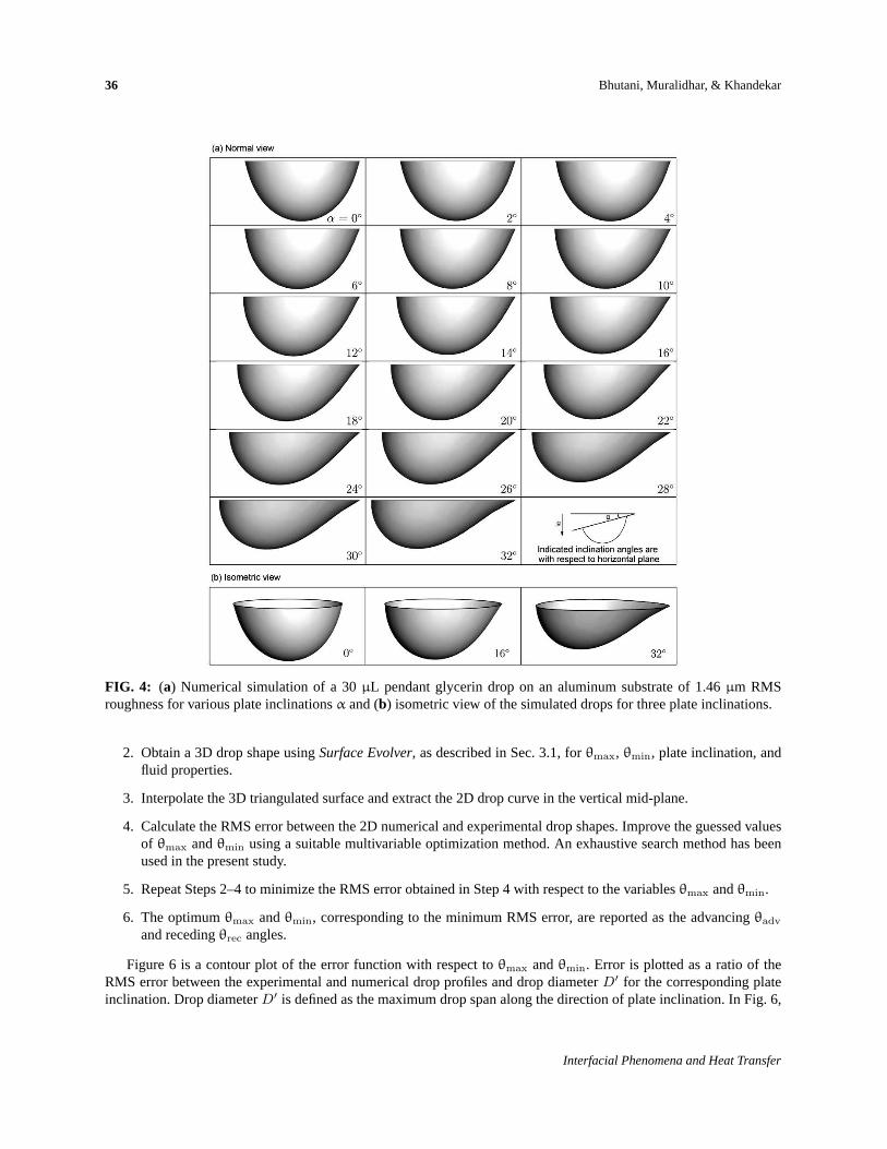
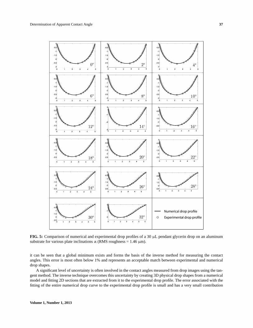
TheSurface Evolvercode used to compute pendant drop shapes was first validated for axisymmetric drops againstresults obtained from the axisymmetric Young–Laplace equation (Appendix 1). Figure 3 compares the shapes of a30µL axisymmetric pendant glycerin drop, with a uniform contact angle of 80◦, predicted usingSurface Evolverandthe solution of Eqs. (A2) and (A3). The match is seen to be quite good. Figure 4 presents 3D drop images obtained fromthe numerical simulation of a 30µL pendant glycerin drop for various plate inclinations. This simulation correspondsto the experimental images shown in Fig. 1(b) for an aluminum substrate of 1.46µm roughness. The shape of adrop deposited on a rough surface is governed by the same physical equation that balances forces, although thesurface roughness alters the contact angle (Bhushan and Jung, 2011). This is realized in the numerical simulation byappropriately settingθmin andθmax in Eq. (1). The correct values ofθmin andθmax were obtained from the inversemethod by comparison against the experiments and the method to obtain these angles is discussed in the next section.Figure 4(a) shows the shapes of the simulated drops from a direction normal to its mid-plane and these are comparableto Fig. 1(b). Figure 4(b) shows an isometric view of these 3D drops for three plate inclinations. A comparison betweenthe experimental and numerical drop shapes can be seen in Fig. 5. The match between the two sets of data is seen tobe good.
3.2 Inverse Technique for Estimating Contact Angles
As noted earlier, the contact angles reported in this study have been estimated using two methods: (1) a tangent methodfor experimental images using digital image processing and (2) an inverse method that minimizes the error betweenthe experimental and numerical drop shapes; the latter being based on assumed contact angles. The inverse methodminimizes the error with respect toθmax andθmin as parameters [Eq. (1)]. An algorithm for calculation of contactangles using the inverse method is presented as follows:
1. Guessθmax andθmin. A good starting guess can be the respective contact angles measured using the tangentmethod.
FIG. 3: Validation of theSurface Evolvercode to predict the shape of a 3D pendant drop; the 3D shape of a 30µLpendant glycerin drop with a contact angle of 80◦ is simulated usingSurface Evolverand is compared with the solutionof the axisymmetric Young–Laplace equation on the mid-plane using the parametric form suggested by Pozrikidis(2009).
Volume 1, Number 1, 2013
36 Bhutani, Muralidhar, & Khandekar
FIG. 4: (a) Numerical simulation of a 30µL pendant glycerin drop on an aluminum substrate of 1.46µm RMSroughness for various plate inclinationsα and (b) isometric view of the simulated drops for three plate inclinations.
2. Obtain a 3D drop shape usingSurface Evolver, as described in Sec. 3.1, forθmax, θmin, plate inclination, andfluid properties.
3. Interpolate the 3D triangulated surface and extract the 2D drop curve in the vertical mid-plane.
4. Calculate the RMS error between the 2D numerical and experimental drop shapes. Improve the guessed valuesof θmax andθmin using a suitable multivariable optimization method. An exhaustive search method has beenused in the present study.
5. Repeat Steps 2–4 to minimize the RMS error obtained in Step 4 with respect to the variablesθmax andθmin.
6. The optimumθmax andθmin, corresponding to the minimum RMS error, are reported as the advancingθadv
and recedingθrec angles.
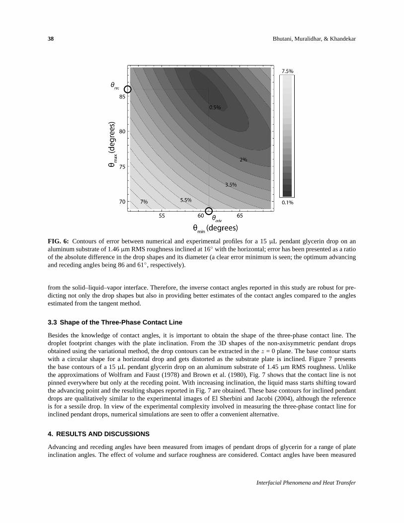
Figure 6 is a contour plot of the error function with respect toθmax andθmin. Error is plotted as a ratio of theRMS error between the experimental and numerical drop profiles and drop diameterD′ for the corresponding plateinclination. Drop diameterD′ is defined as the maximum drop span along the direction of plate inclination. In Fig. 6,
Interfacial Phenomena and Heat Transfer
Determination of Apparent Contact Angle 37
FIG. 5: Comparison of numerical and experimental drop profiles of a 30µL pendant glycerin drop on an aluminumsubstrate for various plate inclinationsα (RMS roughness = 1.46µm).
it can be seen that a global minimum exists and forms the basis of the inverse method for measuring the contactangles. This error is most often below 1% and represents an acceptable match between experimental and numericaldrop shapes.
A significant level of uncertainty is often involved in the contact angles measured from drop images using the tan-gent method. The inverse technique overcomes this uncertainty by creating 3D physical drop shapes from a numericalmodel and fitting 2D sections that are extracted from it to the experimental drop profile. The error associated with thefitting of the entire numerical drop curve to the experimental drop profile is small and has a very small contribution
Volume 1, Number 1, 2013
38 Bhutani, Muralidhar, & Khandekar
FIG. 6: Contours of error between numerical and experimental profiles for a 15µL pendant glycerin drop on analuminum substrate of 1.46µm RMS roughness inclined at 16◦ with the horizontal; error has been presented as a ratioof the absolute difference in the drop shapes and its diameter (a clear error minimum is seen; the optimum advancingand receding angles being 86 and 61◦, respectively).
from the solid–liquid–vapor interface. Therefore, the inverse contact angles reported in this study are robust for pre-dicting not only the drop shapes but also in providing better estimates of the contact angles compared to the anglesestimated from the tangent method.
3.3 Shape of the Three-Phase Contact Line
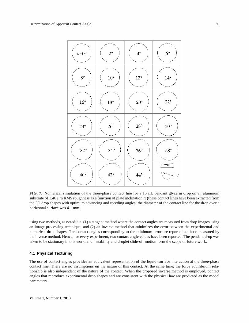
Besides the knowledge of contact angles, it is important to obtain the shape of the three-phase contact line. Thedroplet footprint changes with the plate inclination. From the 3D shapes of the non-axisymmetric pendant dropsobtained using the variational method, the drop contours can be extracted in thez = 0 plane. The base contour startswith a circular shape for a horizontal drop and gets distorted as the substrate plate is inclined. Figure 7 presentsthe base contours of a 15µL pendant glycerin drop on an aluminum substrate of 1.45µm RMS roughness. Unlikethe approximations of Wolfram and Faust (1978) and Brown et al. (1980), Fig. 7 shows that the contact line is notpinned everywhere but only at the receding point. With increasing inclination, the liquid mass starts shifting towardthe advancing point and the resulting shapes reported in Fig. 7 are obtained. These base contours for inclined pendantdrops are qualitatively similar to the experimental images of El Sherbini and Jacobi (2004), although the referenceis for a sessile drop. In view of the experimental complexity involved in measuring the three-phase contact line forinclined pendant drops, numerical simulations are seen to offer a convenient alternative.
4. RESULTS AND DISCUSSIONS
Advancing and receding angles have been measured from images of pendant drops of glycerin for a range of plateinclination angles. The effect of volume and surface roughness are considered. Contact angles have been measured
Interfacial Phenomena and Heat Transfer
Determination of Apparent Contact Angle 39
FIG. 7: Numerical simulation of the three-phase contact line for a 15µL pendant glycerin drop on an aluminumsubstrate of 1.46µm RMS roughness as a function of plate inclinationα (these contact lines have been extracted fromthe 3D drop shapes with optimum advancing and receding angles; the diameter of the contact line for the drop over ahorizontal surface was 4.1 mm.
using two methods, as noted; i.e. (1) a tangent method where the contact angles are measured from drop images usingan image processing technique, and (2) an inverse method that minimizes the error between the experimental andnumerical drop shapes. The contact angles corresponding to the minimum error are reported as those measured bythe inverse method. Hence, for every experiment, two contact angle values have been reported. The pendant drop wastaken to be stationary in this work, and instability and droplet slide-off motion form the scope of future work.
4.1 Physical Texturing
The use of contact angles provides an equivalent representation of the liquid–surface interaction at the three-phasecontact line. There are no assumptions on the nature of this contact. At the same time, the force equilibrium rela-tionship is also independent of the nature of the contact. When the proposed inverse method is employed, contactangles that reproduce experimental drop shapes and are consistent with the physical law are predicted as the modelparameters.
Volume 1, Number 1, 2013
40 Bhutani, Muralidhar, & Khandekar
On surfaces with isotropically distributed roughness, one can expect the Wenzel state to be realized at equilibrium.In general, a drop could be in a Cassie–Baxter state as well. With experimental images as input, the inverse algorithmwould recover the contact angles of this configuration as well. In the experiments, it was expected that the drop wasin the Wenzel state. This expectation was supported by the modified contact angles seen on the inclined surfaces.
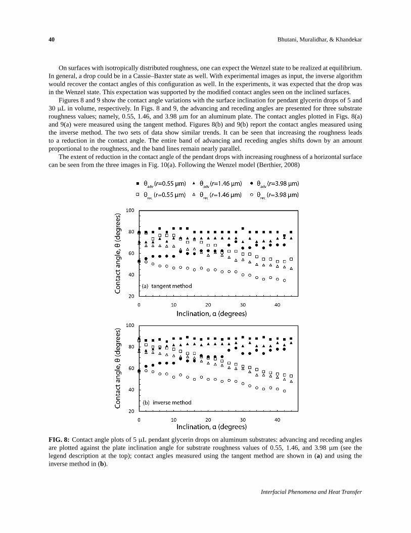
Figures 8 and 9 show the contact angle variations with the surface inclination for pendant glycerin drops of 5 and30 µL in volume, respectively. In Figs. 8 and 9, the advancing and receding angles are presented for three substrateroughness values; namely, 0.55, 1.46, and 3.98µm for an aluminum plate. The contact angles plotted in Figs. 8(a)and 9(a) were measured using the tangent method. Figures 8(b) and 9(b) report the contact angles measured usingthe inverse method. The two sets of data show similar trends. It can be seen that increasing the roughness leadsto a reduction in the contact angle. The entire band of advancing and receding angles shifts down by an amountproportional to the roughness, and the band lines remain nearly parallel.
The extent of reduction in the contact angle of the pendant drops with increasing roughness of a horizontal surfacecan be seen from the three images in Fig. 10(a). Following the Wenzel model (Berthier, 2008)
FIG. 8: Contact angle plots of 5µL pendant glycerin drops on aluminum substrates: advancing and receding anglesare plotted against the plate inclination angle for substrate roughness values of 0.55, 1.46, and 3.98µm (see thelegend description at the top); contact angles measured using the tangent method are shown in (a) and using theinverse method in (b).
Interfacial Phenomena and Heat Transfer
Determination of Apparent Contact Angle 41
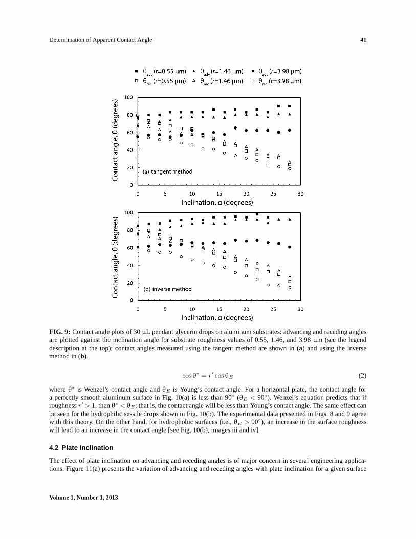
FIG. 9: Contact angle plots of 30µL pendant glycerin drops on aluminum substrates: advancing and receding anglesare plotted against the inclination angle for substrate roughness values of 0.55, 1.46, and 3.98µm (see the legenddescription at the top); contact angles measured using the tangent method are shown in (a) and using the inversemethod in (b).
cosθ∗ = r′ cosθE (2)
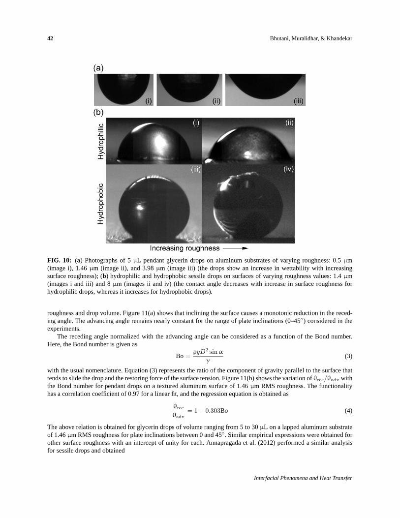
whereθ∗ is Wenzel’s contact angle andθE is Young’s contact angle. For a horizontal plate, the contact angle fora perfectly smooth aluminum surface in Fig. 10(a) is less than 90◦ (θE < 90◦). Wenzel’s equation predicts that ifroughnessr′ > 1, thenθ∗ < θE ; that is, the contact angle will be less than Young’s contact angle. The same effect canbe seen for the hydrophilic sessile drops shown in Fig. 10(b). The experimental data presented in Figs. 8 and 9 agreewith this theory. On the other hand, for hydrophobic surfaces (i.e.,θE > 90◦), an increase in the surface roughnesswill lead to an increase in the contact angle [see Fig. 10(b), images iii and iv].
4.2 Plate Inclination
The effect of plate inclination on advancing and receding angles is of major concern in several engineering applica-tions. Figure 11(a) presents the variation of advancing and receding angles with plate inclination for a given surface
Volume 1, Number 1, 2013
42 Bhutani, Muralidhar, & Khandekar
FIG. 10: (a) Photographs of 5µL pendant glycerin drops on aluminum substrates of varying roughness: 0.5µm(image i), 1.46µm (image ii), and 3.98µm (image iii) (the drops show an increase in wettability with increasingsurface roughness); (b) hydrophilic and hydrophobic sessile drops on surfaces of varying roughness values: 1.4µm(images i and iii) and 8µm (images ii and iv) (the contact angle decreases with increase in surface roughness forhydrophilic drops, whereas it increases for hydrophobic drops).
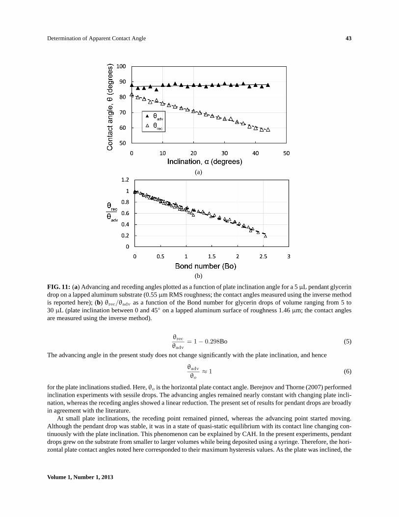
roughness and drop volume. Figure 11(a) shows that inclining the surface causes a monotonic reduction in the reced-ing angle. The advancing angle remains nearly constant for the range of plate inclinations (0–45◦) considered in theexperiments.
The receding angle normalized with the advancing angle can be considered as a function of the Bond number.Here, the Bond number is given as
Bo =ρgD2 sin α
γ(3)
with the usual nomenclature. Equation (3) represents the ratio of the component of gravity parallel to the surface thattends to slide the drop and the restoring force of the surface tension. Figure 11(b) shows the variation ofθrec/θadv withthe Bond number for pendant drops on a textured aluminum surface of 1.46µm RMS roughness. The functionalityhas a correlation coefficient of 0.97 for a linear fit, and the regression equation is obtained as
θrec
θadv= 1− 0.303Bo (4)
The above relation is obtained for glycerin drops of volume ranging from 5 to 30µL on a lapped aluminum substrateof 1.46µm RMS roughness for plate inclinations between 0 and 45◦. Similar empirical expressions were obtained forother surface roughness with an intercept of unity for each. Annapragada et al. (2012) performed a similar analysisfor sessile drops and obtained
Interfacial Phenomena and Heat Transfer
Determination of Apparent Contact Angle 43
(a)
(b)
FIG. 11: (a) Advancing and receding angles plotted as a function of plate inclination angle for a 5µL pendant glycerindrop on a lapped aluminum substrate (0.55µm RMS roughness; the contact angles measured using the inverse methodis reported here); (b) θrec/θadv as a function of the Bond number for glycerin drops of volume ranging from 5 to30 µL (plate inclination between 0 and 45◦ on a lapped aluminum surface of roughness 1.46µm; the contact anglesare measured using the inverse method).
θrec
θadv= 1− 0.298Bo (5)
The advancing angle in the present study does not change significantly with the plate inclination, and hence
θadv
θo≈ 1 (6)
for the plate inclinations studied. Here,θo is the horizontal plate contact angle. Berejnov and Thorne (2007) performedinclination experiments with sessile drops. The advancing angles remained nearly constant with changing plate incli-nation, whereas the receding angles showed a linear reduction. The present set of results for pendant drops are broadlyin agreement with the literature.
At small plate inclinations, the receding point remained pinned, whereas the advancing point started moving.Although the pendant drop was stable, it was in a state of quasi-static equilibrium with its contact line changing con-tinuously with the plate inclination. This phenomenon can be explained by CAH. In the present experiments, pendantdrops grew on the substrate from smaller to larger volumes while being deposited using a syringe. Therefore, the hori-zontal plate contact angles noted here corresponded to their maximum hysteresis values. As the plate was inclined, the
Volume 1, Number 1, 2013
44 Bhutani, Muralidhar, & Khandekar
advancing contact angle tried to increase but could not because it had already attained the maximum possible value.The shift in drop mass due to inclination drove the contact line forward at the advancing point, maintaining the ad-vancing angle constant. On the other hand, at the receding point, the contact angle decreased with the inclination. Thehysteresis phenomena exhibited by the contact angles allowed this reduction in the receding angle from its extremevalue and the receding point remained pinned to the substrate. There is a limit up to which the receding contact anglecan decrease as determined by the drop volume, plate inclination, and surface roughness. The drop becomes unstableas soon as the receding contact angle goes below this limiting angle. Instabilities were not captured in our experimentsbecause this study was only concerned with static drops.
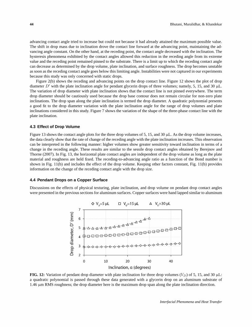
Figure 2(b) shows the receding and advancing points on the drop contact line. Figure 12 shows the plot of dropdiameterD′ with the plate inclination angle for pendant glycerin drops of three volumes; namely, 5, 15, and 30µL.The variation of drop diameter with plate inclination shows that the contact line is not pinned everywhere. The termdrop diameter should be cautiously used because the drop base contour does not remain circular for non-zero plateinclinations. The drop span along the plate inclination is termed the drop diameter. A quadratic polynomial presentsa good fit to the drop diameter variation with the plate inclination angle for the range of drop volumes and plateinclinations considered in this study. Figure 7 shows the variation of the shape of the three-phase contact line with theplate inclination.
4.3 Effect of Drop Volume
Figure 13 shows the contact angle plots for the three drop volumes of 5, 15, and 30µL. As the drop volume increases,the data clearly show that the rate of change of the receding angle with the plate inclination increases. This observationcan be interpreted in the following manner: higher volumes show greater sensitivity toward inclination in terms of achange in the receding angle. These results are similar to the sessile drop contact angles obtained by Berejnov andThorne (2007). In Fig. 13, the horizontal plate contact angles are independent of the drop volume as long as the platematerial and roughness are held fixed. The receding-to-advancing angle ratio as a function of the Bond number isshown in Fig. 11(b) and includes the effect of the drop volume. Keeping other factors constant, Fig. 11(b) providesinformation on the change of the receding contact angle with the drop size.
4.4 Pendant Drops on a Copper Surface
Discussions on the effects of physical texturing, plate inclination, and drop volume on pendant drop contact angleswere presented in the previous sections for aluminum surfaces. Copper surfaces were hand lapped similar to aluminum
FIG. 12: Variation of pendant drop diameter with plate inclination for three drop volumes (VD) of 5, 15, and 30µL:a quadratic polynomial is passed through these data generated with a glycerin drop on an aluminum substrate of1.46µm RMS roughness; the drop diameter here is the maximum drop span along the plate inclination direction.
Interfacial Phenomena and Heat Transfer
Determination of Apparent Contact Angle 45
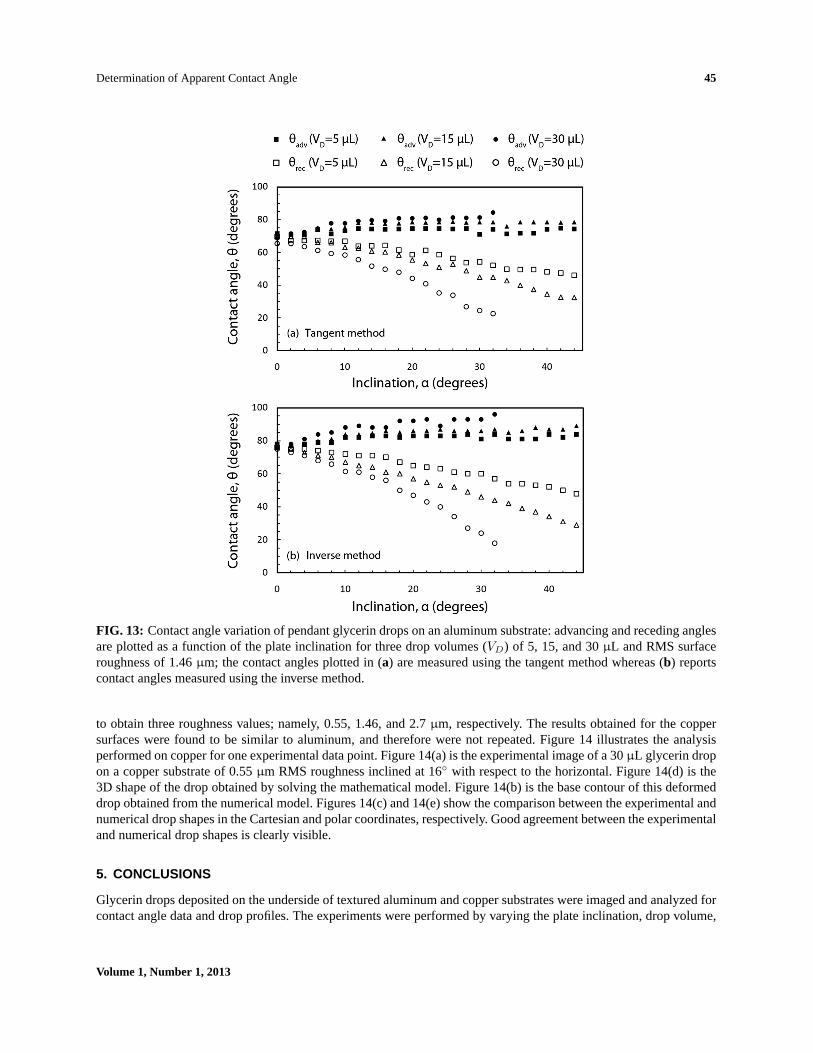
FIG. 13: Contact angle variation of pendant glycerin drops on an aluminum substrate: advancing and receding anglesare plotted as a function of the plate inclination for three drop volumes (VD) of 5, 15, and 30µL and RMS surfaceroughness of 1.46µm; the contact angles plotted in (a) are measured using the tangent method whereas (b) reportscontact angles measured using the inverse method.
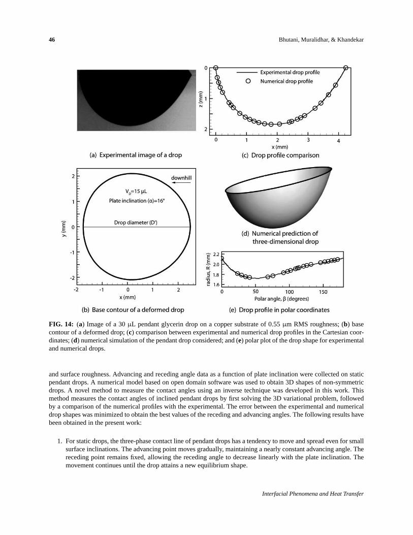
to obtain three roughness values; namely, 0.55, 1.46, and 2.7µm, respectively. The results obtained for the coppersurfaces were found to be similar to aluminum, and therefore were not repeated. Figure 14 illustrates the analysisperformed on copper for one experimental data point. Figure 14(a) is the experimental image of a 30µL glycerin dropon a copper substrate of 0.55µm RMS roughness inclined at 16◦ with respect to the horizontal. Figure 14(d) is the3D shape of the drop obtained by solving the mathematical model. Figure 14(b) is the base contour of this deformeddrop obtained from the numerical model. Figures 14(c) and 14(e) show the comparison between the experimental andnumerical drop shapes in the Cartesian and polar coordinates, respectively. Good agreement between the experimentaland numerical drop shapes is clearly visible.
5. CONCLUSIONS
Glycerin drops deposited on the underside of textured aluminum and copper substrates were imaged and analyzed forcontact angle data and drop profiles. The experiments were performed by varying the plate inclination, drop volume,
Volume 1, Number 1, 2013
46 Bhutani, Muralidhar, & Khandekar
FIG. 14: (a) Image of a 30µL pendant glycerin drop on a copper substrate of 0.55µm RMS roughness; (b) basecontour of a deformed drop; (c) comparison between experimental and numerical drop profiles in the Cartesian coor-dinates; (d) numerical simulation of the pendant drop considered; and (e) polar plot of the drop shape for experimentaland numerical drops.
and surface roughness. Advancing and receding angle data as a function of plate inclination were collected on staticpendant drops. A numerical model based on open domain software was used to obtain 3D shapes of non-symmetricdrops. A novel method to measure the contact angles using an inverse technique was developed in this work. Thismethod measures the contact angles of inclined pendant drops by first solving the 3D variational problem, followedby a comparison of the numerical profiles with the experimental. The error between the experimental and numericaldrop shapes was minimized to obtain the best values of the receding and advancing angles. The following results havebeen obtained in the present work:
1. For static drops, the three-phase contact line of pendant drops has a tendency to move and spread even for smallsurface inclinations. The advancing point moves gradually, maintaining a nearly constant advancing angle. Thereceding point remains fixed, allowing the receding angle to decrease linearly with the plate inclination. Themovement continues until the drop attains a new equilibrium shape.
Interfacial Phenomena and Heat Transfer
Determination of Apparent Contact Angle 47
2. Increasing surface roughness causes a reduction in the apparent contact angles. The result is in accordance withWenzel’s model, which predicts an increase in wettability for increased surface roughness values for hydrophilicsurfaces.
3. The apparent contact angle of a pendant drop on a horizontal surface is not affected by volume. Receding anglesfall with a greater slope for larger drop volumes, clearly showing the effect of body forces on deformation.
4. The base contour deforms from a circular shape as the plate is inclined. The numerical model predicts the basecontour for inclined pendant drops, providing a convenient alternative to difficult experiments.
REFERENCES
Abdelsalam, M. E., Bartlett, P. N., Kelf, T., and Baumberg, J., Wetting of regularly structured gold surfaces,Langmuir, vol. 21, pp.1753–1757, 2005.
Adamiak, K., Capillary and electrostatic limitations to the contact angle in electrowetting-on-dielectric,Microfluid. Nanofluid., vol.2, pp. 471–480, 2006.
Ajaev, V. S., Gambaryan-Roisman, T., and Stephan, P., Static and dynamic contact angles of evaporating liquids on heated surfaces,J. Colloid Interface Sci., vol. 342, no. 2 pp. 550–558, 2010.
Annapragada, S. R., Murthy, J. Y., and Garimella, S. V., Droplet retention on an incline,Int. J. Heat Mass Transfer, vol. 55, pp.1457–1465, 2012.
Barthlott, W. and Neinhuis, C., Purity of the sacred lotus, or escape from contamination in biological surfaces,Planta, vol. 202,pp. 1–8, 1997.
Berejnov, V. and Thorne, R. E., Effect of transient pinning on stability of drops sitting on an inclined plane,Phys. Rev. E, vol. 75,no. 6, p. 066308, 2007.
Berthier, J.,Microdrops and Digital Microfluidics, 2nd ed., Waltham, MA: Hemisphere, 2008.
Bhushan, B. and Jung, Y. C., Natural and biomimetic artificial surfaces for superhydrophobicity, self-cleaning, low adhesion, anddrag reduction,Prog. Mater. Sci., vol. 56, pp. 1–108, 2011.
Bico, J., Marzolin, C., and Quere, D., Pearl drops,Europhys. Lett., vol. 47, no. 2, pp. 220–226, 1999.
Brakke, K., TheSurface Evolver, Exp. Math., vol. 1, no. 2, pp. 141–165, 1992.
Brown, R. A., Orr, F. M., Jr., and Scriven, L. E., Static drop on an inclined plate: Analysis by the finite element method,J. ColloidInterface Sci., vol. 73, no. 1, pp. 76–87, 1980.
Carey, V. P.,Liquid–Vapor Phase-Change Phenomena, pp. 342–351, New York: Hemisphere, 1992.
Cassie, A. B. D. and Baxter, S., Wettability of porous surfaces,Trans. Faraday Soc., vol. 40, pp. 546–551, 1944.
Chaudhury, M. K. and Whitesides, G. M., How to make water run uphill,Science, vol. 256, no. 5063, pp. 1539–1541, 1992.
Cheng, P., Li, D., Boruvka, L., Rotenberg, Y., and Neumann, A. W., Automation of axisymmetric drop shape analysis for measure-ments of interfacial tensions and contact angles,Colloids Surf., vol. 43, pp. 151–167, 1990.
Dimitrakopoulos, P. and Higdon, J. J. L., On the gravitational displacement of three-dimensional fluid droplets from inclined solidsurfaces,J. Fluid Mech., vol. 395, pp. 181–209, 1999.
Dingle, N. M., Tjiptowidjojo, K., Basaran, O. A., and Harris, M. T., A finite element based algorithm for determining interfacialtension from pendant drop profiles,J. Colloid Interface Sci., vol. 286, no. 2, pp. 647–660, 2005.
El Sherbini, A. I. and Jacobi, A. M., Liquid drops on vertical and inclined surfaces: I. An experimental study of drop geometry,J.Colloid Interface Sci., vol. 273, no. 2, pp. 556–565, 2004.
Extrand, C. W. and Kumagai, Y., Liquid drops on an inclined plane: The relation between contact angles, drop shape, and retentiveforce,J. Colloid Interface Sci., vol. 170, no. 2, pp. 515–521, 1995.
Fox, H. W. and Zisman, W. A., The spreading of liquids on low energy surfaces. I. polytetrafluoroethylene,J. Colloid Sci., vol. 5,no. 6, pp. 514–531, 1950.
Iliev, S. D., Iterative method for the shape of static drops,Comput. Methods Appl. Mech. Eng., vol. 126, no. 3, pp. 251–265, 1995.
Kalinin, Y., Berejnov, V., and Thorne, R. E., Controlling microdrop shape and position for biotechnology using micropatternedrings, Microfluid. Nanofluid., vol. 5, pp. 449–454, 2008.
Volume 1, Number 1, 2013
48 Bhutani, Muralidhar, & Khandekar
Lee, Y. L., The wettability of solid surfaces modified by vacuum deposition of stearic acid,Colloid Surf., A, vol. 155, nos. 2–3, pp.221–229, 1999.
Liao, Q., Shi, Y., Fan, Y., Zhu, X., and Wang, H., Numerical simulations of the equilibrium shape of liquid droplets on gradientsurfaces,Appl. Therm. Eng., vol. 29, no. 2, pp. 372–379, 2009.
Milinazzo, F. and Shinbrot, M., A numerical study of a drop on a vertical wall,J. Colloid Interface Sci., vol. 121, no. 1, pp.254–264, 1988.
Mugele, F. and Baret, J. C., Electrowetting: From basics to applications,J. Phys.: Condens. Matter, vol. 17, pp. R705–R774, 2005.
Pozrikidis, C.,Fluid Dynamics: Theory, Computation, and Numerical Simulation, 2nd ed., New York: Springer, 2009.
Quere, D., Rough ideas on wetting,Physica A, vol. 313, nos. 1–2, pp. 32–46, 2002.
Rio, O. D. and Neumann, A. W., Axisymmetric drop shape analysis: Computational methods for the measurement of interfacialproperties from the shape and dimensions of pendant and sessile drops,J. Colloid Interface Sci., vol. 196, no. 2, pp. 136–147,1997.
Santos, M. J. and White, J. A., Theory and simulation of angular hysteresis on planar surfaces,Langmuir, vol. 27, no. 24, pp.14868–14875, 2011.
Shastry, A., Case, M. J., and Bohringer, K. F., Directing droplets using microstructured surfaces,Langmuir, vol. 22, no. 14, pp.6161–6167, 2006.
Sikarwar, B. S., Battoo, N. K., Khandekar, S., and Muralidhar, K., Dropwise condensation underneath chemically textured surfaces:Simulation and experiments,ASME J Heat Transfer, vol. 133, no. 2, p. 021501, 2011.
Style, R. W. and Dufresne, E. R., Static wetting on deformable substrates, from liquids to soft solids,Soft Matter, vol. 8, pp.7177–7184, 2012.
Tuteja, A., Choi, W., McKinley, G. H., Cohen, R. E., and Rubner, M. F., Design parameters for superhydrophobicity and super-oleophobicity,MRS Bull., vol. 33, pp. 752–758, 2008.
Wenzel, R. N., Resistance of solid surfaces to wetting by water,Ind. Eng. Chem., vol. 28, pp. 988–994, 1936.
Winkels, K. G., Peters, I. R., Evangelista, F., Riepen, M., Daerr, A., Limat, L., and Snoeijer, J. H., Receding contact lines: Fromsliding drops to immersion lithography,Eur. Phys. J. Spec. Top., vol. 192, no. 1, pp. 195–205, 2011.
Wolfram, E. and Faust, R.,Wetting, Spreading and Adhesion, J. F. Padday, ed., pp. 213–222, London: Academic, 1978.
APPENDIX 1: PARAMETRIC FORM OF THE AXISYMMETRIC YOUNG–LAPLACE EQUATION
The Young–Laplace equation represents the force equilibrium for a static drop and takes the following form for anaxisymmetric pendant drop (Pozrikidis, 2009):
2κm =ζ
l2+ B (A1)
Here,ζ is the symmetry axis;σ is the other axis perpendicular toζ andσ = f(ζ) with the origin at the lowest pointof the pendant drop;κm is the mean curvature given byκm = (κ1 + κ2)/2, whereκ1 = −f ′′/(1 + f ′2)3/2 andκ2 = 1/f(1 + f ′2)1/2; l =
√γ/∆ρg is the capillary length. One can introduce a parameterψ, the angle made by the
tangent on the drop at any point on its surface in Eq. (A1), to convert it into the following set of ordinary differentialequations:
dζ
dψ=
sin ψ
Q(A2)
dσ
dψ= −cos ψ
Q(A3)
Here,Q = (sin ψ/σ)− (ζ/l2)−B andψ varies from 0 at the origin toθ (the contact angle) at the contact line. Theboundary conditions are
ζ (0) = 0 and σ (0) = 0 (A4)
and the drop volume constraint is
Interfacial Phenomena and Heat Transfer
Determination of Apparent Contact Angle 49
π
0∫
−d
σ2dζ = VD (A5)
with d as the maximum drop height in thez direction.Equations (A2) and (A3) are solved with the boundary conditions [Eq. (A4)] using a fourth-order Runge–Kutta
(RK4) method. Because the value ofB is unknown to start with, the Newton–Raphson method is iteratively used withthe volume constraint [Eq. (A5)] to get the correct value of parameterB.
APPENDIX 2: THREE-DIMENSIONAL YOUNG–LAPLACE EQUATION
The Young–Laplace equation for a 3D drop is given as (Pozrikidis, 2009)
2κm =∆ρ
γg · z + B (B1)
Here,κm is the mean curvature of the liquid–air interface;∆ρ = ρliq − ρair; γ is the surface tension of the liquid;B = ∆p/γ, where∆p is the excess pressure in the liquid contained within the drop. For a 3D drop surfacez =f(x, y), the curvature of the drop is given by
κm =12
(1 + f2
x
)fyy − 2fxfyfxy +
(1 + f2
y
)fxx(
1 + f2x + f2
y
)3/2(B2)
Here, x and y are the coordinates in the planez = 0 of the three-phase drop contact line as shown in Fig. 2(b).Substituting Eq. (B2) into Eq. (B1) gives the governing equation for the shape of a non-symmetric drop in terms ofthe functionf(x, y). The governing equation is solved subject to the following boundary conditions:
f (S) = 0, where S (x, y) = 0 is the contact line of the drop (B3)
∇f · n = |∇f | sin θ on S (x, y) = 0 (B4)
Here,n is a normal to the planez = 0, andθ is the contact angle and a function of the azimuthal angleφ [Fig. 2(b)].Since the excess pressure∆p(= B×γ) is an unknown, the governing equation is solved with a drop volume constraint
∫f (x, y) dxdy = VD, given (B5)
Solving Eq. (B1) with boundary conditions (B3) and (B4) and constraint (B5) is a challenging problem. An alternativeapproach based on the variational principle has been used in the present study. It is implemented algorithmically usingthe open-source software,Surface Evolver(Brakke, 1992).
Volume 1, Number 1, 2013


![Author's personal copy - IITKhome.iitk.ac.in/~samkhan/Bio_data/publications/Khandekar_26.pdf · Author's personal copy Nusselt number under such conditions. Celata et al.[19] observed](https://img.pdfslide.us/doc/110x75/5ecb238ba62ad97ce66ac608/authors-personal-copy-samkhanbiodatapublicationskhandekar26pdf-authors.jpg)