Embed Size (px)
Citation preview

Detection and Fine 3D Pose Estimationof Texture-less Objects in RGB-D Images
Tomas Hodan], Xenophon Zabulis[, Manolis Lourakis[, Stepan Obdrzalek], Jirı Matas]]Center for Machine Perception, Czech Technical University in Prague, Czech Republic
hodantom|xobdrzal|[email protected][Institute of Computer Science, Foundation for Research and Technology - Hellas, Heraklion, Greece
zabulis|[email protected]
Abstract— Despite their ubiquitous presence, texture-less ob-jects present significant challenges to contemporary visualobject detection and localization algorithms. This paper pro-poses a practical method for the detection and accurate 3Dlocalization of multiple texture-less and rigid objects depictedin RGB-D images. The detection procedure adopts the slidingwindow paradigm, with an efficient cascade-style evaluation ofeach window location. A simple pre-filtering is performed first,rapidly rejecting most locations. For each remaining location,a set of candidate templates (i.e. trained object views) is iden-tified with a voting procedure based on hashing, which makesthe method’s computational complexity largely unaffected bythe total number of known objects. The candidate templatesare then verified by matching feature points in differentmodalities. Finally, the approximate object pose associatedwith each detected template is used as a starting point fora stochastic optimization procedure that estimates accurate 3Dpose. Experimental evaluation shows that the proposed methodyields a recognition rate comparable to the state of the art,while its complexity is sub-linear in the number of templates.
I. INTRODUCTION
Texture-less, smooth and uniformly colored objects occurfrequently in robotic applications that range from personalrobotics to intelligent manipulation and assembly. Commonto such applications is the requirement of identifying andaccurately localizing known objects so that they can be actedupon by a robot end effector. Fig. 1 depicts an exampleof a robotic assembly scenario involving several texture-lessobjects. An arm with a gripper is assigned the task of pickingup electrical fuses, at arbitrary locations in its workspace, andinserting them into the sockets of corresponding fuse boxes.
The method detailed in this paper aims at the reliablesimultaneous detection of multiple texture-less objects withlow false detection rate, real time performance, and sub-centimeter accuracy in object localization. The input to themethod consists of RGB-D images provided by a consumer-grade depth sensor such as Kinect. Such sensors providealigned color and depth images that concurrently captureboth the appearance and geometry of a scene.
This work was supported in part by the EC FP7 programme under grantno. 270138 DARWIN, by CTU student grant SGS15/155/OHK3/2T/13,and by the Technology Agency of the Czech Republic research programTE01020415 (V3C – Visual Computing Competence Center) TE01020415.
Fig. 1. Left: Detection of multiple instances of multiple texture-lessobjects (fuses and fuse boxes of different types) in a robotic assembly task.Right: Superimposed renderings of object models at the estimated 3D poses.
While object recognition is a long-standing and widelystudied problem, most attention until recently has been paidto the recognition of textured objects, for which discrim-inative appearance features, invariant to changes in poseand illumination, can be readily extracted [1]. These objectsare often assumed to have piece-wise planar surfaces. Theirappearance variations can be therefore modeled by a simplegeometric transformation (e.g. similarity), which can bereliably determined from the rich textural information. Can-didate object locations in the scene are typically determinedby identifying so-called interest points or interest regions [2],a strategy which drastically reduces the overall computa-tional cost compared to exhaustive image search. However,when applied to texture-less objects, interest point detectorstypically fail to identify corresponding image regions andcommon local appearance descriptors are no longer discrim-inative enough to provide reliable correspondences [3].
Recognition and localization of texture-less objects ischallenging in several respects. An object’s appearance isdominated by its shape, its material properties and by theconfiguration of light sources. Unless these are known in
2015 IEEE/RSJ International Conference on Intelligent Robots and Systems (IROS)Congress Center HamburgSept 28 - Oct 2, 2015. Hamburg, Germany
978-1-4799-9993-4/15/$31.00 ©2015 IEEE 4421
109 108 105 102 100-101 100-101
Scanning
window
locations
Detections
+ rough 3D
poses
Fine 3D
poses
Pre-filteringHypothesis
GenerationVerification
Fine 3D Pose
Estimation
Non-max
Suppression
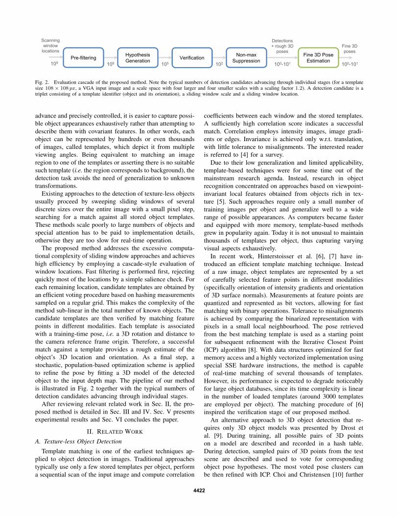
Fig. 2. Evaluation cascade of the proposed method. Note the typical numbers of detection candidates advancing through individual stages (for a templatesize 108 × 108 px, a VGA input image and a scale space with four larger and four smaller scales with a scaling factor 1.2). A detection candidate is atriplet consisting of a template identifier (object and its orientation), a sliding window scale and a sliding window location.
advance and precisely controlled, it is easier to capture possi-ble object appearances exhaustively rather than attempting todescribe them with covariant features. In other words, eachobject can be represented by hundreds or even thousandsof images, called templates, which depict it from multipleviewing angles. Being equivalent to matching an imageregion to one of the templates or asserting there is no suitablesuch template (i.e. the region corresponds to background), thedetection task avoids the need of generalization to unknowntransformations.
Existing approaches to the detection of texture-less objectsusually proceed by sweeping sliding windows of severaldiscrete sizes over the entire image with a small pixel step,searching for a match against all stored object templates.These methods scale poorly to large numbers of objects andspecial attention has to be paid to implementation details,otherwise they are too slow for real-time operation.
The proposed method addresses the excessive computa-tional complexity of sliding window approaches and achieveshigh efficiency by employing a cascade-style evaluation ofwindow locations. Fast filtering is performed first, rejectingquickly most of the locations by a simple salience check. Foreach remaining location, candidate templates are obtained byan efficient voting procedure based on hashing measurementssampled on a regular grid. This makes the complexity of themethod sub-linear in the total number of known objects. Thecandidate templates are then verified by matching featurepoints in different modalities. Each template is associatedwith a training-time pose, i.e. a 3D rotation and distance tothe camera reference frame origin. Therefore, a successfulmatch against a template provides a rough estimate of theobject’s 3D location and orientation. As a final step, astochastic, population-based optimization scheme is appliedto refine the pose by fitting a 3D model of the detectedobject to the input depth map. The pipeline of our methodis illustrated in Fig. 2 together with the typical numbers ofdetection candidates advancing through individual stages.
After reviewing relevant related work in Sec. II, the pro-posed method is detailed in Sec. III and IV. Sec. V presentsexperimental results and Sec. VI concludes the paper.
II. RELATED WORK
A. Texture-less Object Detection
Template matching is one of the earliest techniques ap-plied to object detection in images. Traditional approachestypically use only a few stored templates per object, performa sequential scan of the input image and compute correlation
coefficients between each window and the stored templates.A sufficiently high correlation score indicates a successfulmatch. Correlation employs intensity images, image gradi-ents or edges. Invariance is achieved only w.r.t. translation,with little tolerance to misalignments. The interested readeris referred to [4] for a survey.
Due to their low generalization and limited applicability,template-based techniques were for some time out of themainstream research agenda. Instead, research in objectrecognition concentrated on approaches based on viewpoint-invariant local features obtained from objects rich in tex-ture [5]. Such approaches require only a small number oftraining images per object and generalize well to a widerange of possible appearances. As computers became fasterand equipped with more memory, template-based methodsgrew in popularity again. Today it is not unusual to maintainthousands of templates per object, thus capturing varyingvisual aspects exhaustively.
In recent work, Hinterstoisser et al. [6], [7] have in-troduced an efficient template matching technique. Insteadof a raw image, object templates are represented by a setof carefully selected feature points in different modalities(specifically orientation of intensity gradients and orientationof 3D surface normals). Measurements at feature points arequantized and represented as bit vectors, allowing for fastmatching with binary operations. Tolerance to misalignmentsis achieved by comparing the binarized representation withpixels in a small local neighbourhood. The pose retrievedfrom the best matching template is used as a starting pointfor subsequent refinement with the Iterative Closest Point(ICP) algorithm [8]. With data structures optimized for fastmemory access and a highly vectorized implementation usingspecial SSE hardware instructions, the method is capableof real-time matching of several thousands of templates.However, its performance is expected to degrade noticeablyfor large object databases, since its time complexity is linearin the number of loaded templates (around 3000 templatesare employed per object). The matching procedure of [6]inspired the verification stage of our proposed method.
An alternative approach to 3D object detection that re-quires only 3D object models was presented by Drost etal. [9]. During training, all possible pairs of 3D pointson a model are described and recorded in a hash table.During detection, sampled pairs of 3D points from the testscene are described and used to vote for correspondingobject pose hypotheses. The most voted pose clusters canbe then refined with ICP. Choi and Christensen [10] further
4422

augmented the point pair feature with color information. Theefficiency and performance of these methods depend directlyon the complexity of the 3D scene, which might limit theirapplicability to real-time applications.
Another class of methods relies solely on intensity edges,e.g. [11], [12], [3]. Albeit such methods can operate very fast,their recognition capability is inherently lower compared tomethods also taking into account depth information. Cai etal. [11] employed a sliding window approach with hypothesisgeneration based on hashing distances and orientations of thenearest edges from points on a fixed regular grid. We use asimilar hashing scheme in the proposed method.
B. 3D Pose Estimation
A common aspect of the approaches mentioned in Sec. II-A is that the pose associated with the detected object isapproximate. This is due to the limited resolution of thepose sampling process employed in training or possible mis-matches, and necessitates the refinement of the retrieved posewith a geometric optimization step. The ICP algorithm [8]is the most common choice for this purpose. ICP representsthe gold standard method for geometrically aligning two setsof points whose relative pose is approximately known. How-ever, when the two point sets are relatively far apart or havea small overlap, ICP’s strategy of matching closest pointsgenerates large numbers of incorrect correspondences. Thesituation is aggravated by the inevitable presence of noiseand outliers. As a result, ICP can easily get stuck in localminima and its performance largely depends on the qualityof initialization. To counter this, numerous enhancements tothe basic ICP have been proposed that aim to improve thespeed of convergence or increase robustness to local minima,outlying points and noise [13]. These enhancements often re-quire considerable trial and error for tuning their parametersto a particular application. Here we take a different approachand refine 3D pose with an optimization scheme based onParticle Swarm Optimization (PSO) [14]. PSO has proven tobe an effective framework for dealing with other flavors ofpose estimation, e.g. [15], [16].
III. DETECTION OF TEXTURE-LESS OBJECTS
Detection of objects in an input RGB-D image is basedon a sliding window approach, operating on a scale pyramidbuilt from the image. Let L denote the set of all testedlocations. The number of locations |L| is a function ofimage resolution, spatial image sampling by the slidingwindow (e.g. every 5 pixels), scale range (e.g. two or fouroctaves), and scale space discretisation. The known objectsare represented with a set T of template images – RGB-D images of a fixed size. There are several thousandsof templates per object, capturing its appearance from allpossible viewing angles, but from a fixed distance. Thetraining distance, which then affects the depth channel of anRGB-D template, is object-specific but fixed for all templatesof a certain object. This distance is chosen so that the objectwould optimally fill the template image if observed witha camera with identical intrinsic parameters (focal length
and resolution) as the camera observing later the test scene.Each template is associated with the object ID, the trainingdistance Zt and the object orientation R0 it represents.
In general, every window wl, l = (x, y, s), l ∈ L, needsto be tested against every template, which makes the asymp-totic complexity O(|L||T |). This is computationally verydemanding even for moderate numbers of known objects.We therefore propose a cascaded evaluation, where the setof candidate locations L is quickly reduced (Sec. III-A) andthe candidate templates T are pruned (Sec. III-B) before thetemplate matching itself (Sec. III-C) is performed.
A. Pre-filtering of Window Locations
To reduce the number of image locations, an image win-dow is first assessed with a simple objectness measure [17],[18], i.e. its likelihood that it contains any of the objects.This corresponds to a two-class classifier distinguishingbetween background and object classes, with the object classencompassing all the templates in T .
Our objectness measure is based on the number of depth-discontinuity edgels within the window, and is computedwith the aid of an integral image for efficiency. Depth-discontinuity edgels arise at pixels where the response of theSobel operator, computed over the depth image, is above athreshold θe, which is set to 30% of the physical diameter ofthe smallest object in the database. The window is classifiedas containing an object if its number of depth edgels is atleast 30% of the number of depth edgels in the templatecontaining the least amount of them. This setting is tolerantto partial occlusions but still strong enough to prune mostof the window locations – roughly 90% to 99% of them inimages of our robot workspace (Fig. 1), depending on thescene clutter. Only image windows that pass the objectnesstest are processed further.
B. Hypothesis Generation
In this phase, a small subset of candidate templates isquickly identified for each image window that passed theobjectness test. Up to N templates with the highest proba-bilities pt(t|wl), t ∈ T are retrieved. This can be seen asa multi-class classification problem where there is one classfor each training template, but none for the background.
The procedure retrieves candidate templates from multiple(for robustness) trained hash tables, which is a constant com-plexity O(1) operation in the number of stored templates.Each hash table h ∈ H is indexed by a trained set Mh
of measurements taken on the window wl or template t,discretized into a hash key. Mh is different for each table.The table cells contain lists of templates with the same key,the lists are then used to vote for the templates. A templatecan receive up to |H| votes, in which case all the template’smeasurement sets (for all the tables) would be discretised tothe same hash keys as measurements on the window wl. Upto N templates with the highest number of votes, and withat least v votes, are passed onward to the next step of thedetection cascade. The voting is still an O(|T |) operation foreach wl.
4423

Fig. 3. Templates and test windows are hashed using measurements fromtrained triplets of grid points. Left: Sample triplets which are valid for theshown template, i.e. their points lie in the object mask. Right: A triplet isdescribed by depth differences {d′1, d′2} and normal vectors {n1,n2,n3}.
Fig. 4. Feature points in different modalities whose consistency is evaluatedin the hypothesis verification. The points are trained independently for eachtemplate. Left to right: surface normals, image gradients, depth, color.
Measurement sets Mh and their quantization. Thehashing/voting procedure was inspired by the work ofCai et al. [11]. A regular grid of 12 × 12 reference pointsis placed over the training template or sliding window.This yields 144 locations from which k-tuples are sampled.We use triplets in our setup, i.e. k = 3 (Fig. 3). Eachlocation is assigned with a depth d and a surface normaln. A measurement set Mh is a vector consisting of k − 1relative depth values and k normals,Mh = (d2h−d1h , d3h−d1h , . . . , dkh
−d1h ,n1h , . . . ,nkh). The relative depths dih−
d1h are quantized into 5 bins each, with the quantizationboundaries learned from all the training templates to provideequal frequency binning, i.e. each bin contains the samenumber of templates. To quantize surface normals we use theapproach proposed in [7], where the normals are quantizedto 8 discrete values based on their orientation. For tripletsof reference points we have two relative depths and threenormals, leading to a hash table size of 5283 = 12800 bins.
Training-time selection of measurement sets. To providerobustness to occlusion and noise, multiple hash tables arebuilt, which differ in the selection of the k-tuples drawnfrom the 144 reference points. The k-tuples can be chosenrandomly. Alternatively, they can be optimally selected to(a) cover maximally independent measurements (for robust-ness), and (b) to fill the tables as uniformly as possible (forstable detection time). The optimal selection is unfortunatelyNP -complete, therefore we employ a hybrid heuristic strat-egy. We first randomly generate a set of m, m � |H|, k-tuples and then retain the subset with the largest joint entropyof the quantized measurements.
For the results reported below, |H| = 100 hash tables wereemployed, chosen from m = 5000. The minimal number ofvotes per template was v = 3 and the maximum number ofcandidates passed to the verification stage was N = 100.
C. Hypothesis Verification
The verification stage corresponds to the traditional tem-plate matching. Thanks to the template selection in theprevious step, only up to N templates are considered foreach image window wl that passed the initial objectnesstest. This makes the complexity of this stage constant in thenumber of stored templates. Since the templates were alreadyidentified in the previous step, the verification can be seen asa set of up to N separate two-class classification problemsdiscriminating between the object represented by a templateand the background class, i.e. p(obj|ti, wl) ≶ p(bkg|ti, wl).
The verification proceeds in a sequence of tests evaluatingthe following: I object size in relation to distance, II sampledsurface normals, III sampled image gradients, IV sampleddepth map, and V sampled color. The tests are orderedaccording to increasing computational cost. Any failed testclassifies the window as non-object – corresponding to eitherthe background, or an object not represented by template ti– and subsequent tests are not evaluated.
Test I verifies that the observed object size (i.e. the levelof the scale pyramid) corresponds to its distance measuredin the depth map. The object is expected at distance Ze
calculated as Ze = Zts, where s is the scale factor of thepyramid level and Zt is the template’s training distance. If themeasured depth Zw is within the interval |Ze/
√f, Ze ·
√f |,
where f is the discretization factor of the scale space, thedepth Zw is considered to be feasible, otherwise the test fails.
Tests II and III verify orientation of surface normals andintensity gradients at several feature points. Following [19],the point locations are greedily extracted during the trainingstage, independently for each template (Fig. 4). The featurepoints for the surface normal orientation test are extractedat locations with locally stable orientation of normals (i.e.further away from depth discontinuities). For the intensitygradient orientation test, the feature points are extracted atlocations with large gradient magnitude (i.e. typically on theobject contour). We extract 100 points in both cases. Theorientations are quantized and compared template-against-sliding window, which can be done very fast by bitwiseoperations using response maps described in [6].
The depth map test IV and the color test V reuse thelocations of feature points extracted for the surface normaltest II. In the depth test, difference d between the depth in thetemplate and the depth in the window is calculated for eachfeature point. A feature point is matched if |d− dm| < kD,where dm is the median value of ds over all feature points,D is the physical object diameter, and k is a coefficient (setto 0.05 in our experiments). Finally, pixel colors in test Vare compared in the HSV space, as done in [19].
A template passes the tests II to V if at least θc ofthe feature points have a matching value within a smallneighbourhood. In our experiments θc = 60% to toleratepartial occlusions, and the extent of the local neighborhoodis 5 × 5 pixels to compensate for the sliding window step,and for the discretization of orientations during training. Averified template that passes all the tests is assigned a final
4424

score computed as m =∑
i∈{II...V} ci, where ci is thefraction of matching feature points in tests II to V.
D. Non-maxima Suppression
The verified templates are accumulated from all differentlocations and scales. Since different views of one object areoften alike, and since multiple objects may by rather similar,unique detections are identified by repeatedly retaining thecandidate with the highest score r, and removing all detec-tions that have a large overlap with it. The score is calculatedas r = m(a/s), where m is the verification score definedabove, s is the detection scale, and a is the area of the objectin the considered template. Weighting the score by the objectarea favours detections which explain more of the scene (e.g.when a cup is seen from a side, with the handle visible, weprefer a template depicting the handle over other templateswhere the handle is occluded, but which would otherwiseyield the same matching score). The retained detections arepassed to the 3D pose estimation stage, together with theapproximate 3D poses which have been associated with thetraining templates.
IV. FINE 3D POSE ESTIMATION
Fine 3D pose estimation refers to the accurate computationof translation and rotation parameters that define an object’sposition and orientation in space, assuming that approximateinitial values for these parameters are provided. This processreceives as inputs a mesh model of the object, an initial objectpose {R0, t0}, a depth image and the sensor’s intrinsics andoutputs a refined pose {R, t}. Objects are represented witharbitrary 3D mesh models, which can originate from CADdrawings or from digital scans. A mesh M is comprised ofan ordered set of 3D vertex points V and an ordered set Gof triplet indices upon V that define the mesh triangles. The3D oriented bounding box B of each model is precomputedusing the eigenvectors of V ’s covariance matrix.
Candidate poses {Ri, ti} are generated and then evaluatedby using them to synthesize renderings of M, producingdepth images Si (see Sec. IV-B). A scoring function yieldsscore o(i), which quantifies the similarity between eachimage Si and the input using depth, edge and orientation cues(Sec. IV-C). PSO is used to optimize the scoring functionand find the pose whose rendered depth image is the mostsimilar to the input one (Sec. IV-D). An overview of theapproach is provided in Fig. 5 whereas its components arebriefly described in the following subsections. A detailedpresentation and evaluation of our pose estimation pipelinecan be found in [20].
A. Initialization
The initial pose used to bootstrap pose estimation can bequite crude. The projection on the sensor of the model atthe initial pose determines a 2D, axis-aligned bounding boxb. This box is inflated proportionally to the distance of theinitial pose to mitigate any pose inaccuracies and is assumedto enclose most of the projection of the target object on theinput image.
Fig. 5. Pose estimation for an electrical fuse and fuse box. Left: Initialposes superimposed on a captured image (their misalignment can be seenby zooming in). Thumbnails show in magnification captured depths anddetected edges (bottom), along with color-coded surface normals (top)in the region of the fuse box. Right: Refined poses. Thumbnails showcorresponding fuse box depths and surface normals obtained by rendering.
To suppress sensor noise, the acquired depth image ismedian filtered with a 5× 5 kernel and the result is retainedas image D. Depth shadows and other shortcomings ofconsumer depth sensors manifest themselves as invalid pixelsin D, not contributing with 3D points. Surface normals forvalid depth pixels are estimated by local least-squares planefitting and stored in N [21]. Binary image E is computedfrom D, by thresholding the output of the Sobel operatorapplied to D. The distance transform T of E is computedfor later use. The above computations are parallelized on aGPU at the pixel level, while the computation of T uses theparallel formulation of [22]. To evaluate an input frame, onlythe depth image D is uploaded to the GPU which then usesit to compute N and T . No other input data exchange withthe GPU occurs during pose estimation.
B. Pose Hypotheses Rendering
A rendering process simulates depth images of the targetobject at a hypothesized pose against a blank background.Pose rendering is formulated as follows. Transform {R0, t0}brings the model in an approximate location and orientation,in the depth sensor’s reference frame. Candidate poses areparametrized relative to this initial pose, using a relativetranslation ti and an “in place” rotation Ri about the centroidc of points in V . Specifically, the model is first translatedby −c, rotated by Ri, and translated back to place by c.Rotation Ri is the product of primitive rotations about the3 axes: Ri = Rx(θi) ·Ry(φi) ·Rz(ωi). The transformationmodel point x undergoes is thus Ri ·(x−c)+c+ti. To avoidrepeated transformations, the initial and candidate poses arecombined into the following:
Ri ·R0 · x+Ri · (t0 − c) + c+ ti. (1)
The rotational component of candidate poses is parameter-ized using Euler angles whereas their translation is parame-terized with Euclidean coordinates. The model transformedaccording to Eq. (1), is rendered in depth image Si. Depthedges and surface normals of Si are computed and stored inbinary image Ei and data structure Ni, respectively.
Computation and storage of Si, Ei, and Ni is delegated tothe GPU. The process employs Z-buffering to respect visi-bility and realistically render self-occlusions. Parallelization
4425

is performed at two levels of granularity. At a fine level,rendering is parallelized upon the triangles of the renderedmesh. At a coarser level, multiple hypotheses are renderedsimultaneously, with a composite image gathering all render-ings. In this manner, multiple hypotheses are evaluated in asingle batch, resulting in better utilization of GPU resourcesand reduced communication. Edge detection is applied once,directly upon the composite image.
C. Pose Hypotheses Evaluation
A candidate pose is evaluated with respect to the extent towhich it explains the input depth image. Objective functiono(·) avails a score o(i) and considers the similarity of depthvalues, surface normals, as well as depth edges between Dand Si. Two range images are corresponded in terms of theircoordinates and are compared as follows.
Depth values are directly compared between D and Si forpairs of pixels. For n pixel pairs, depth differences δk, arecomputed and the cumulative depth cost term is defined as:
di =∑n
k=11/(|δk|+ 1), (2)
where |δk| is set to ∞ if greater than threshold dT (20mmin our implementation) to avoid comparing with backgroundsurfaces. For the same n pairs of pixels, the cost due tosurface normal differences is quantified as:
ui =∑n
k=11/(|γk|+ 1), (3)
where γk is the angle between the two surface normals, pro-vided by their dot product. Edge differences are aggregatedin an edge cost using E and Ei. Let m be the number ofedgels of Ei within b. For each such edgel j, let εj denotethe distance from its closest edgel in D which is looked upfrom T . The corresponding edge cost term is then:
ei =∑m
j=11/(εj + 1). (4)
Each of the cost terms in Eqs. (2), (3) and (4) involvestwo ordered pixel sets, one from each image D and Si,that contain the pixel locations to be compared. As di, ui,and ei have different numeric ranges, the combined cost isdefined by their product o(i) = −di · ei · ui, where theminus sign is used to ensure that optimal values correspondto minima, since di, ei and ui are non-negative. Summingthe reciprocals of partial differences |δk|, |γk| and εj rewardsposes that maximize the support (i.e. spatial overlap) betweenthe compared regions of D and Si. The objective functionimproves when more pixels in the rendered depth mapclosely overlap with the imaged surfaces in the input image.
As no segmentation is employed, inaccurate pose hypothe-ses might cause the rendered object to be compared againstpixels imaging background or occluding surfaces. To counterthis, only pixels located within b are considered. Hypothesesthat correspond to renderings partially outside b obtain apoor similarity score and the solution does not drift towardsan irrelevant surface. Also, during the evaluation of eachhypothesis, the oriented bounding box Bi that correspondsto hypothesis i is computed by transforming B according to
Eq. (1). By so doing, depth pixels from D that correspond to3D points outside Bi are not considered in the comparison,as they are irrelevant to the hypothesis being evaluated.
D. Pose Estimation
The search space for the pose estimation is constrainedin a 6D neighborhood of the initial pose estimate. Eachdimension of the pose search space is bounded, defining asearch hyperrectangle centered on the initial pose estimate.As the cost of an exhaustive search in R6 is prohibitive,a numerical optimization approach is adopted to minimizeobjective function o(·). This minimization is performed withPSO, which stochastically evolves a population of candidatesolutions dubbed particles, that explore the parameter spacein runs called generations. PSO does not require knowledgeof the derivatives of the objective function, depends on veryfew parameters and requires a relatively small number ofobjective function evaluations until convergence. Comparedto gradient-based optimization methods, PSO has a widerbasin of convergence, exhibiting better robustness to localminima. Furthermore, as particles evolve independently ateach generation, it is amenable to an efficient parallel imple-mentation [20].
V. EXPERIMENTS AND EVALUATION
A. Object Localization
The presented method was evaluated quantitatively withthe aid of the publicly available dataset by Hinterstoisseret al. [19]. This dataset includes 15 texture-less objects andprovides for each a 3D mesh model and a test sequenceconsisting of approximately 1200 RGB-D frames in VGAresolution. The test sequences feature heavy 2D and 3Dclutter, mild occlusions and large viewpoint variations andare accompanied by the ground truth object pose for eachframe. The task is to localize the given object in each frame,i.e. to detect it and estimate its 3D pose.
Training templates were rendered from the provided 3Dmodels so that they uniformly covered the upper view hemi-sphere (with a step of 10◦ in both azimuth and elevation).To achieve invariance to rotation around the optical axis, anin-plane rotation to each template (from −40◦ to 40◦ witha step of 10◦) was also applied. In total, each object wasrepresented by 2916 templates of size 108 × 108 px. Eachtest image was scanned at 9 scales (4 larger and 4 smallerscales with scaling factor 1.2) with a scanning step of 5 px.
We compare our method to the LINEMOD [6] andLINEMOD++ [7] methods of Hinterstoisser et al. and themethod of Drost et al. [9]. These methods were alreadybriefly described in Sec. II-A; here we provide more detailsregarding their relation to our method. LINEMOD followsan exhaustive template matching approach. LINEMOD++extends it by two post-processing verification steps. Specifi-cally, a color check and a depth check (by a rough but fastICP) are performed in order to prune hypotheses. A finer ICPis then carried out for the best of the remaining hypotheses.The essential difference of our method is the addition of the
4426
Sequence Our method LINEMOD++ LINEMOD Drost et al.1. Ape 93.9 95.8 69.4 86.52. Benchvise 99.8 98.7 94.0 70.73. Bowl 98.8 99.9 99.5 95.74. Box 100.0 99.8 99.1 97.05. Cam 95.5 97.5 79.5 78.66. Can 95.9 95.4 79.5 80.27. Cat 98.2 99.3 88.2 85.48. Cup 99.5 97.1 80.7 68.49. Driller 94.1 93.6 81.3 87.310. Duck 94.3 95.9 75.9 46.011. Glue 98.0 91.8 64.3 57.212. Hole punch 88.0 95.9 78.4 77.413. Iron 97.0 97.5 88.8 84.914. Lamp 88.8 97.7 89.8 93.315. Phone 89.4 93.3 77.8 80.7Average 95.4 96.6 83.0 79.3
TABLE IRECOGNITION RATES [%] FOR THE DATASET OF [19] AND km = 0.1
(i.e. THE PERCENTAGE OF OBJECTS LOCALIZED WITH AN ERROR
SMALLER THAN 10% OF THEIR DIAMETER).
pre-filtering and the hypothesis generation stage, avoidingthe exhaustive search.
We used the same quantification of pose error as in [19].That is, for the ground truth pose {Rg, tg} and the estimatedpose {Re, te}, the error is e = 1/ν
∑i |gi − ei|, where
gi = Rgxi + tg , ei = Rexi + te, and i enumerates the νvertices of V . For objects with ambiguous pose due to theirsymmetry (namely “Cup”, “Bowl”, “Box” and “Glue”), theerror is computed as e = 1/ν
∑iminj |gi − ej |. An object
is considered to be correctly localized if e ≤ kmd, wherekm is a fixed coefficient and d is the diameter of the model,i.e. the maximum distance between any of its vertices.
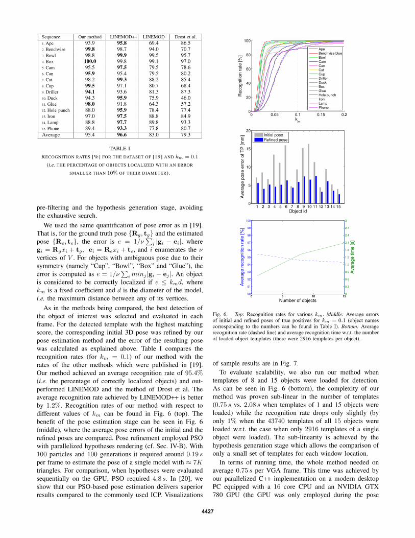
As in the methods being compared, the best detection ofthe object of interest was selected and evaluated in eachframe. For the detected template with the highest matchingscore, the corresponding initial 3D pose was refined by ourpose estimation method and the error of the resulting posewas calculated as explained above. Table I compares therecognition rates (for km = 0.1) of our method with therates of the other methods which were published in [19].Our method achieved an average recognition rate of 95.4%(i.e. the percentage of correctly localized objects) and out-performed LINEMOD and the method of Drost et al. Theaverage recognition rate achieved by LINEMOD++ is betterby 1.2%. Recognition rates of our method with respect todifferent values of km can be found in Fig. 6 (top). Thebenefit of the pose estimation stage can be seen in Fig. 6(middle), where the average pose errors of the initial and therefined poses are compared. Pose refinement employed PSOwith parallelized hypotheses rendering (cf. Sec. IV-B). With100 particles and 100 generations it required around 0.19 sper frame to estimate the pose of a single model with ≈ 7Ktriangles. For comparison, when hypotheses were evaluatedsequentially on the GPU, PSO required 4.8 s. In [20], weshow that our PSO-based pose estimation delivers superiorresults compared to the commonly used ICP. Visualizations
0 0.05 0.1 0.15 0.20
20
40
60
80
100
Re
co
gn
itio
n r
ate
[%
]
km
Ape
Benchvise blue
Bowl
Cam
Can
Cat
Cup
Driller
Duck
Box
Glue
Hole punch
Iron
Lamp
Phone
1 2 3 4 5 6 7 8 9 10 11 12 13 14 150
5
10
15
20
Object id
Ave
rag
e p
ose
err
or
of
TP
[m
m]
Initial pose
Refined pose
0 5 10 1590
91
92
93
94
95
96
97
98
99
100
Number of objects
Ave
rag
e r
eco
gn
itio
n r
ate
[%
]
0 5 10 150
0.3
0.6
0.9
1.2
1.5
1.8
2.1
2.4
2.7
3
Ave
rag
e t
ime
[s]
Fig. 6. Top: Recognition rates for various km. Middle: Average errorsof initial and refined poses of true positives for km = 0.1 (object namescorresponding to the numbers can be found in Table I). Bottom: Averagerecognition rate (dashed line) and average recognition time w.r.t. the numberof loaded object templates (there were 2916 templates per object).
of sample results are in Fig. 7.To evaluate scalability, we also run our method when
templates of 8 and 15 objects were loaded for detection.As can be seen in Fig. 6 (bottom), the complexity of ourmethod was proven sub-linear in the number of templates(0.75 s vs. 2.08 s when templates of 1 and 15 objects wereloaded) while the recognition rate drops only slightly (byonly 1% when the 43740 templates of all 15 objects wereloaded w.r.t. the case when only 2916 templates of a singleobject were loaded). The sub-linearity is achieved by thehypothesis generation stage which allows the comparison ofonly a small set of templates for each window location.
In terms of running time, the whole method needed onaverage 0.75 s per VGA frame. This time was achieved byour parallelized C++ implementation on a modern desktopPC equipped with a 16 core CPU and an NVIDIA GTX780 GPU (the GPU was only employed during the pose
4427

Fig. 7. Sample 3D pose estimations on the dataset of [19] (cropped).
Fig. 8. Cropped close-ups of 3D pose estimations in a manipulation task.
estimation). As reported in [19], the method of Drost neededon average 6.3 s and LINEMOD++ only 0.12 s. The lattertime was achieved with a highly optimized implementationusing heavy SSE parallelization and a limited scale space (foreach object, only a limited set of scales were considered).With a similar level of optimization, we expect our method torun even faster since it evaluates only a small set of templatesfor each window. In the case of multiple object detectionand localization that arises often in robotic applications, ourmethod is expected to outperform LINEMOD++ in terms ofrunning time.
B. Robotic Application
The intended application of the proposed method relates torobotic manipulation and assembly of objects. Figs. 1 and 8demonstrate its suitability for a manipulation task with elec-trical parts along with its tolerance to mild occlusions. Whena robotic gripper was present in the scene, its posture wasaccurately provided by motor encoders and used to mask outthe corresponding pixels in the image, preventing them fromcontaminating pose estimation. As shown in Fig. 6 (middle),the poses estimated with the presented method achieve a sub-centimeter average accuracy in the estimated pose (for therecognition of 95.4%). This meets the requirements imposedby the compliant grippers of the industrial robotic arms usedin our application (Staubli RX130 and RX90).
VI. CONCLUSION
An approach for texture-less object detection and 3D poseestimation in RGB-D images has been presented. It is basedon a sliding window approach with a cascade-style evaluationof each window location. Sub-linearity in the number of
training templates is achieved by an efficient voting pro-cedure based on hashing which generates a small set ofcandidate templates for each window location. The templatesare verified in several modalities and approximate objectposes associated with the matched templates are refined bya stochastic optimization scheme. Experiments on a publicdataset have demonstrated that the proposed method detectsobjects with a recognition rate comparable to the state of theart and achieves sub-centimeter accuracy in localization. Themethod is therefore well-suited to multiple object detection,a commonly required task in robotic applications.
REFERENCES
[1] A. Collet, M. Martinez, and S. Srinivasa, “The MOPED framework:Object Recognition and Pose Estimation for Manipulation,” I. J.Robotic Res., vol. 30, no. 10, pp. 1284–1306, 2011.
[2] T. Tuytelaars and K. Mikolajczyk, “Local invariant feature detectors:A survey,” Found. Trends. Comput. Graph. Vis., vol. 3, no. 3, pp.177–280, July 2008.
[3] F. Tombari, A. Franchi, and L. Di, “BOLD features to detect texture-less objects,” in ICCV, 2013, pp. 1265–1272.
[4] R. Brunelli, Template Matching Techniques in Computer Vision: The-ory and Practice. Wiley Publishing, 2009.
[5] D. Lowe, “Object recognition from local scale-invariant features,” inICCV, vol. 2, 1999, pp. 1150–1157.
[6] S. Hinterstoisser, S. Holzer, C. Cagniart, S. Ilic, K. Konolige,N. Navab, and V. Lepetit, “Multimodal templates for real-time de-tection of texture-less objects in heavily cluttered scenes,” in ICCV,2011.
[7] S. Hinterstoisser, C. Cagniart, S. Ilic, P. Sturm, N. Navab, P. Fua,and V. Lepetit, “Gradient response maps for real-time detection oftexture-less objects,” IEEE PAMI, 2012.
[8] P. Besl and N. McKay, “A Method for Registration of 3-D Shapes,”PAMI, vol. 14, no. 2, pp. 239–256, 1992.
[9] B. Drost, M. Ulrich, N. Navab, and S. Ilic, “Model globally, matchlocally: Efficient and robust 3d object recognition,” in CVPR, 2010,pp. 998–1005.
[10] C. Choi and H. Christensen, “3D Pose Estimation of Daily ObjectsUsing an RGB-D Camera,” in IROS, 2012, pp. 3342–3349.
[11] H. Cai, T. Werner, and J. Matas, “Fast detection of multiple textureless3-D objects,” in ICVS, ser. LNCS, 2013, vol. 7963, pp. 103–112.
[12] D. Damen, P. Bunnun, A. Calway, and W. Mayol-Cuevas, “Real-time Learning and Detection of 3D Texture-less Objects: A ScalableApproach,” in BMVC, Sep 2012, pp. 1–12.
[13] S. Rusinkiewicz and M. Levoy, “Efficient Variants of the ICP Algo-rithm,” in 3DIM, 2001, pp. 145–152.
[14] R. Poli, J. Kennedy, and T. Blackwell, “Particle Swarm Optimization,”Swarm Intelligence, vol. 1, no. 1, pp. 33–57, 2007.
[15] I. Oikonomidis, N. Kyriazis, and A. A. Argyros, “Efficient model-based 3D tracking of hand articulations using Kinect,” in BMVC, 2011,pp. 1–11.
[16] S. Ivekovic, E. Trucco, and Y. Petillot, “Human Body Pose Estima-tion with Particle Swarm Optimisation,” Evolutionary Computation,vol. 16, no. 4, pp. 509–528, 2008.
[17] B. Alexe, T. Deselaers, and V. Ferrari, “Measuring the objectness ofimage windows,” Pattern Analysis and Machine Intelligence, IEEETransactions on, vol. 34, no. 11, pp. 2189–2202, Nov 2012.
[18] M.-M. Cheng, Z. Zhang, W.-Y. Lin, and P. Torr, “BING: Binarizednormed gradients for objectness estimation at 300fps,” in CVPR, 2014,pp. 3286–3293.
[19] S. Hinterstoisser, V. Lepetit, S. Ilic, S. Holzer, G. Bradski, K. Konolige,and N. Navab, “Model based training, detection and pose estimationof texture-less 3D objects in heavily cluttered scenes,” in ACCV, 2012.
[20] X. Zabulis, M. Lourakis, and P. Koutlemanis, “3D object pose re-finement in range images,” in ICVS, ser. LNCS, 2015, vol. 9163, pp.263–274.
[21] H. Badino, D. Huber, Y. Park, and T. Kanade, “Fast and accuratecomputation of surface normals from range images,” in ICRA, 2011,pp. 3084–3091.
[22] T.-T. Cao, K. Tang, A. Mohamed, and T.-S. Tan, “Parallel BandingAlgorithm to Compute Exact Distance Transform with the GPU,” inI3D, 2010, pp. 83–90.
4428