Embed Size (px)
Citation preview

Computers & Fluids 114 (2015) 141–150
Contents lists available at ScienceDirect
Computers & Fluids
journal homepage: www.elsevier .com/ locate /compfluid
Detailed micro-particle deposition patterns in the human nasal cavityinfluenced by the breathing zone
http://dx.doi.org/10.1016/j.compfluid.2015.02.0200045-7930/� 2015 Elsevier Ltd. All rights reserved.
⇑ Corresponding author at: School of Aerospace, Mechanical & ManufacturingEngineering, RMIT University, PO Box 71, Bundoora, VIC 3083, Australia.
E-mail addresses: [email protected] (Y.D. Shang), [email protected] (K. Inthavong), [email protected] (J.Y. Tu).
Y.D. Shang a,b, K. Inthavong a, J.Y. Tu a,b,⇑a School of Aerospace, Mechanical & Manufacturing Engineering, RMIT University, PO Box 71, Bundoora, VIC 3083, Australiab School of Architecture, Tsinghua University, PO Box 2021, Beijing 100084, China
a r t i c l e i n f o a b s t r a c t
Article history:Received 22 August 2014Received in revised form 16 December 2014Accepted 28 February 2015Available online 11 March 2015
Keywords:Nasal cavityMicro-particleBreathing zoneCFD
The breathing region connects the nasal cavity with the outside environmental air where flow is acceler-ated through the nostrils. Particles introduced into the nasal cavity without considering the breathingregion neglect the influence of facial features and realistic boundary conditions at the nostrils. In thisstudy, a new nasal cavity model is reconstructed combining facial features and an ambient environmentfocusing on the breathing region. The inhaled air from outside the nose is investigated and comparedwith a model that consists of the nasal cavity alone. An improved 2D surface mapping technique isapplied to the 3D nasal cavity to visualize the particle deposition patterns onto a planar geometry.Using this technique, deposition of micron particles from 0.4 lm to 30 lm were investigated, andtrajectories of 2.5 lm, 10 lm and 20 lm were compared with the ‘nasal-only’ case. Particle depositionefficiency curves and particle trajectories are plotted to show that the inclusion of the external noseand breathing region causes: (i) a change in the fluid flow within the anterior nasal cavity half but theflow patterns regulate in the posterior half; (ii) minimal difference for 2.5 lm particle depositionpatterns; (iii) significant differences in 10 and 20 lm particle deposition patterns where more particlesare deposited in the posterior nasal regions.
� 2015 Elsevier Ltd. All rights reserved.
1. Introduction
The human nasal cavity plays an important role in respirationdue to its three major physiological functions: air-conditioning, fil-tering and olfaction. The inhaled air flow behaviour in the nasalcavity can be investigated by reconstructing the airway from com-puted tomography (CT), magnetic resonance imaging (MRI), orex vivo by plastination of cadavers. Experimental studies of airflowbehaviour have been performed using particle image velocimetry(PIV) [1,2], or by dye injection into the flow stream [3,4].However, due to the complex geometry, and perturbation intro-duced by experimental equipment, direct measurements insidecast models are difficult [5]. When considering particle inhalation,this problem becomes further compounded.
Computational Fluid Dynamics (CFD) analysis of nasal functionhave been investigated since the pioneering work by Keyhani et al.[6] in 1997. Since then computational studies have investigated its
anatomical form, airflow patterns, and fluid-particle interactions togain a better understanding of: respiration function [7–10]; air-conditioning [11,12]; and surgical implications [13–17]. When asecondary particle phase is introduced, inhaled particles coupledto the airflow field, allow studies of nasal drug delivery [18–22];and inhalation toxicology [23–25] or general particle depositionstudies [26,27]. The work by Wang et al. [28] indicated depositionefficiency for 22 lm particles in the nasal cavity reached 100% forlight breathing and revealed deposition hot spots for micron-parti-cles. Similarly Shi et al. [29] and Shanley et al. [30] produced highdeposition for 20 lm particles at a flow rate of 7.5 L/min; all col-lecting in the anterior nasal cavity.
Within these studies a lacking feature is the omission of theexternal nose and facial features. This simplification influencesthe airflow patterns significantly in the breathing zone, outsidethe nasal cavity [31–33]. The exclusion of the outer environmentmeans that an artificial and representative boundary conditionthe nostril inlet is applied. Recently Taylor et al. [34] investigatedairflow in the nasal cavity by comparing different inflow boundaryconditions (flat, parabolic and using an external face) and showedthat regional wall shear stress and olfactory flux are sensitive toinflow boundary profiles by up to 100%. Later, studies by Zhu

142 Y.D. Shang et al. / Computers & Fluids 114 (2015) 141–150
et al. [35] and Lu et al. [36] compared nasal airway flow patternsfor three and ten computational models, respectively, thatincluded the external nose and face. However these two studiesdid not consider particle inhalation.
Since airborne particles are transported by the fluid phase, theeffects caused by facial features on particle deposition in the res-piratory system should be considered. Studies by Se et al. [37]and Inthavong et al. [38] investigated the inhalability of particlesvia a realistic human head and indicated velocity vectors weredirected slightly upwards towards the nostril opening, leading toa lower critical area for small particles and a higher critical areafor heavy particles. Li et al. [39] included a nasal cavity modelinside a simplified standing mannequin and placed in a large room.Their results showed the airflow field in the breathing zone exhib-ited high acceleration and particle track profiles at the nostrilopenings were not uniformly distributed, which is typically thecase when the external environment is omitted.
In this study, we investigate the influence of the external noseand face on fluid and particle dynamics during inhalation. A newcomputational nasal model connected with realistic facial featureswas generated from CT scans and reconstructed carefully via imageprocessing software. The airflow field was simulated by CFD fromthe external environment into the nasal cavity through to thenasopharynx. These results were compared with results obtainedfrom the same nasal cavity model but without the external facialfeatures and environment. Instead of an entire large room we focuson the breathing region reduce computational costs and increasingthe resolution of the flow field in the breathing region. To identifyand compare the precise particle deposition position, a mappingtechnique to convert the 3D nasal cavity onto a 2D-plane is pre-sented. Particles with sizes from 0.4 lm to 30 lm were investi-gated and representative sizes (2.5 lm, 10 lm, and 20 lmrepresenting PM2.5, PM10 and larger ambient particles respec-tively) were tracked and its deposition positions in the nasal cavityplotted for both models.
Fig. 1. Computational model of the nasal cavity, combined with detailed facial featureextension attached at the nasopharynx for the outlet. (b) Isometric view of the computposterior nasal valve, turbinate and choanae regions labelled as C–C0 , G–G0 and J–J0 .
2. Method
2.1. Computational geometry
An integrated human respiratory model including a nasal cavityand head was reconstructed from computed tomography (CT)images of an Asian male and labelled as ‘NC03’. CT images (dimen-sion: 512� 512� 512 with pixel size 0.5 mm) were segmentedsemi-automatically using the medical image-processing softwareMaterialise-Mimics to extract a 3D volume. This was refined man-ually, by excluding noise and repairing unrealistic regions.Further step-like surface regions were improved and smoothedusing the 3D modelling software Geomagic Studio. For simplicity,openings to sinuses were omitted as their impact to air flow pat-tern and micron particle deposition were negligible [40]. The facialdetails were retained while the back of the head was omitted. Anartificial straight pipe extension of 5 cm was attached to thenasopharynx to allow a more realistic boundary condition at theoutlet. The surrounding ambient air was modelled with a simplecubic volume having dimensions of 15 cm-width, 12 cm-heightand 20 cm-depth shown in the isometric view in Fig. 1.
Thirteen cross sections (from A–A0 to M–M0) were created alongthe main flow path of the nasal cavity geometry. The main pas-sages are bounded by three bony folds (inferior/middle/superiorturbinate), beneath which narrow airway passages called the mea-tuses are located. They expand from C–C0 located posterior to thenasal valve, and finally merge together in the choanae labelled asJ–J0. The narrow main passage is represented by cross-section G–G0.
2.2. Mesh generation
The nasal cavity geometries were imported to ICEM-CFD to gen-erate the mesh. Inside the nasal cavity domain, a mesh grid of7.5 million unstructured tetrahedral cells was created with meshsize of 0.5 mm. For the ambient air in front of the face, 2.0 million
s and the external domain. (a) Frontal view of the whole model with an artificialational domain. (c) Thirteen cross sections along the main flow path and shapes of

Y.D. Shang et al. / Computers & Fluids 114 (2015) 141–150 143
tetrahedral cells with the mesh size of 4 mm were first generated.Around the breathing zone 4 mm away from the tip of nostrilswhere air was accelerated rapidly, the mesh grid size was furtherrefined to 2 mm (Fig. 2). Twenty prism layers adjacent to the nasalwall with total height of 0.2 mm were generated to improve theboundary layer resolution. Considering the narrowed meatusesand turbinate passages (somewhere approximately 1 mm), themesh was further refined to guarantee sufficient resolution of theairflow field in the narrowest region. The entire mesh requiredapproximately 1 GB of RAM and 10 h to converge (below 10�7 forresiduals) when running in the Ansys Fluent 14.5 in parallel ontwo 2.53 GHz quad core processors. A mesh independence testwas performed prior against lower resolution meshed models, byinvestigating velocity profiles at a number of locations inside andoutside the nasal cavity, and by comparing the particle depositionefficiency on the nasal cavity wall.
2.3. Surface mapping technique
Visualising particle deposition on the intricate nasal cavity wallin 3D is difficult because of the high curvature and overlapping sur-faces. A surface mapping technique projecting the nasal cavity sur-faces from 3D space to 2D space was developed. This was based onthe ISOMAP algorithm [41] and is coupled with sub-programswritten in Matlab 2013b [42]. The nasal cavity was divided into leftand right chambers, and cut along the bottom of each chamber toguarantee correct topology. It was further separated into smalleranatomical regions of interest by characteristic curves. In thisstudy, we improve the surface mapping technique presented byInthavong et al. [42] with new subregions shown in Fig. 3. Thenew mapping is achieved through the following steps:
Fig. 2. Computational mesh of the ‘with-face’ model. (a) mesh of the external domain wiof 2 mm and (b) relative mesh of the external domain with inside the nasal cavity that hasprism layers with the total width of 0.2 mm are generated to enhance the accuracy and
(i) Separate each chamber into the vestibule (region-1), themain passage (region-2 to region-10) and the nasopharynx(region-11) by cutting along the two cross sections at C–C0
and J–J0.(ii) Divide the main passage region into lateral part and septal
regions (region-3) by curves located at the top of thegeometry.
(iii) Further separating the lateral region into 8 sub-regions:atrium, olfactory, superior/middle/inferior turbinate andsuperior/middle/inferior meatus, to distinguish particledeposition positions on the nasal walls.
Among the separated regions, the olfactory region situated at thetop of the nasal cavity is highly sensitive to toxic particle depositiondue to its direct access to the brain [43]. Fig. 3c shows the mappeddomain normalized to an orthogonal 2D-space. For each chamber,a characteristic curve at the top of the geometry (dashed line inFig. 3) was constrained horizontally, while the cross-section curvesextracted from C–C0 and J–J0 were constrained vertically enforcingan orthogonal domain for direct comparison between the twochambers and different models. High curvature regions such asthe meatus (region 6, 8, 10) situated on opposing lateral sides ofthe nasal cavity were compressed during the mapping process. Byusing this improved normalization method, a direct comparisonbetween left and right chambers can be analysed.
2.4. Fluid flow and boundary conditions
This study assumes stagnant air around the human body andalso neglects the human body thermal plume. The air flow is mod-elled by using the steady, laminar, incompressible and isothermalNavier–Stokes equations.
th a base mesh size of 4 mm and refinements in the breathing region with mesh sizea mesh size of 0.5 mm. (c) internal mesh taken at the turbinate cross-section. (d) 20to improve the results near boundaries.

Fig. 3. (a) Top view of the nasal cavity labelled and colour coded with the region numbers b) Lateral view of the nasal cavity. Dashed lines located at the top of cavity areconstrained lines that become the horizontal lines in the 2D mapping, while the other constrained lines are located at the posterior nasal valves and the choanae whichbecome the vertical lines in the 2D mapping. (c) the 2D mapped model sub-divided into eleven regions according to the anatomy. (For interpretation of the references tocolour in this figure legend, the reader is referred to the web version of this article.)
Fig. 4. Representation of discrete particle release locations for the ‘with-face’model. 105 particles were released throughout the external domain uniformly.
144 Y.D. Shang et al. / Computers & Fluids 114 (2015) 141–150
The continuity equation is:
@
@xiðuiÞ ¼ 0 ð1Þ
The momentum equation is:
qgui@ui
@xj¼ � @p
@xiþ @
@xjl @ui
@xj
� �ð2Þ
where u and p are the air velocity and the air pressure, respectively.The air density are dropped out of the continuity equation due tothe incompressible fluid assumption. A laminar airflow represent-ing light breathing was used following Hahn et al. [44] and Kellyet al. [1]’s experimental work, and Keyhani et al. [6]’s simulationwhich suggested laminar flows up to a rate of 24 L/min.
Second-order schemes were used to approximate the momen-tum equation while the pressure–velocity coupling was handledthrough the SIMPLE method. To initiate inhalation, a pressure dif-ference is created between the lung and the ambient environment.The boundaries of the external domain in front of the face were setto constant zero pressure to represent atmosphere pressure, whilethe extension outlet was set to a negative pressure outlet. The set-tings allowed air to flow from the external environment into thenasal cavity at a constant flow rate of 10 L/min and 15 L/minrepresenting a light breathing condition. For the ‘nasal-only’ casewithout the external domain, the pressure inlets were located attruncated planes at the nostrils (A–A0).
2.5. Particle tracks simulation
Particles with sizes from 0.4 lm to 30 lm representing micron-sized pollutants were released uniformly through the externaldomain in front of the face shown in Fig. 4. For each particle size1� 105 aerodynamic particles with zero velocity were introduced.For the ‘nasal-only’ model, 1� 105 particles were released uni-formly on the nostrils at cross-section A–A0. Each individual
particle was tracked using a Lagrangian approach with one-wayfluid phase coupling and thus the particles are assumed to be adilute disperse phase. The particle tracking was terminated whena particle either reached the nasal cavity wall, whereby it wasassumed to deposit, or escaped through the computational domainvia the extension of the nasal pharynx. The deposition efficiency(DE) in the nasal cavity was defined by:
DE ¼ ND
NI� 100% ð3Þ

Table 1Comparison of nasal cavity geometry dimensions from the NC03 model used in thisstudy with those in the literature.
Parameter NC03-model Literature
Left Right
Cavity volume (cm3) 14.031 12.474 13.8–22.4a
Nostril Area (cm2) 0.815 0.771 0.5–1.3b
Nostril Perimeter (cm) 3.713 3.646 4.65c
Nasal Valve Area (cm2) 0.708 0.643 0.46–1.21d
a Doorly et al. [4].b Lang [46].c Anthony et al. [47].d Doorly et al. [5].
Fig. 6. Pressure drop against flow rates (from 0 to 15 L/min) compared withreported data from Kelly et al. [50], Schroeter et al. [51], Wen et al. [7], and Ge et al.[40].
Y.D. Shang et al. / Computers & Fluids 114 (2015) 141–150 145
where ND is the number of particles depositing in the nasal cavitywall, and NI is the number of particles inhaled into the nasal cavity.
The gravity and drag force were considered in transporting theparticles and its force balance equation is given as:
dup
dt¼ FDðug � upÞ þ
gðqp � qgÞqp
ð4Þ
The drag force FD, is dependent on the drag coefficient based onMorsi and Alexander [45] defined by:
CD ¼ a1 þa2
Repþ a3
Re2p
ð5Þ
where the a1; a2 and a3 are empirical constants for smooth sphericalparticle over several ranges of droplet Reynolds number.Gravitational settling is given by g and the density term q, disap-pears when the particle density is much larger than the fluid in thisstudy (e.g., qp � qg)
3. Results and discussion
3.1. Geometry model and pressure drop comparison
Fig. 5 and Table 1 compares the cross-sectional areas from thenasal cavity model used in this study (labelled NC03) with othermodels in the literature. The cross-sectional area is taken normalto the air flow path along the x-axis from the nostril tip throughto the nasopharynx. From the anterior tip, it decreases to a mini-mum at the nasal valve, labelled ‘B’, then increases to a maximumat the turbinate region, labelled ‘G’. The cross sectional areadecreases again until the two chambers merge at the choanaeregion labelled as ‘J’.
In the region between cross sections ‘C’ and ‘J’, the cross-sec-tional areas of the left cavity are larger than those of the right cav-ity (Fig. 1(c)), resulting in a larger volume (Table 1). Other reporteddata show similar CSA profiles while their total lengths are 1–2 cmlonger than that of NC03.
Inhaled air flowing through the nasal cavity is driven by a pres-sure difference induced from the negative pressure in the lungsduring the expansion stage of respiration. The pressure differencewithin the nasal cavity itself is then used as a measure of flowresistance based on the nasal geometry. For flow rates up to15 L/min, a laminar flow model was applied. Furthermore to beconsistent with existing experimental and computational resultsdata, the truncated ‘nasal-only’ model was used for the
Fig. 5. Cross-sectional area variation with x-axis representing the distance betweenthe tip of nostril and centroids of cross-sections.
comparison. Fig. 6 shows the pressure drop between nostril inletsand the outlet at the nasopharynx (excluding the artificial exten-sion) for inhalation rates up to 15 L/min. At these flow rates, thecorresponding range of Reynolds number at nostrils is from 0 to1090. The pressure drop increases in a near-linear profile, and lieswithin range of the reported experimental and numerical data.
3.2. Airflow pattern
Two velocity magnitude iso-surfaces in the ambient air areshown in Fig. 7 to determine the breathing zone caused by aninhalation rate of 15 L/min. At the nostrils, a ‘nostril-inlet velocity’is found, which is 0.3 m/s in this case and highlighted as a red iso-surface. The breathing zone in this study is defined by a velocityiso-surface that is 10% of the ’nostril-inlet velocity’, coloured byblue surface indicating a velocity of 0.03 m/s. This is a semi-ellip-soidal region that is approximately 2.5 cm horizontal and 5 cm ver-tical to the nose. To better visualize this fluid behaviour, additionalstreamlines that enter the nostrils are shown along with thebreathing zone in Fig. 7b. These airflow patterns suggest that par-ticles released far from the face have to behave like tracer-gases(e.g. <2.5 lm) to follow the fluid streamlines for particle inhalationto occur. Heavier particles (e.g. >10 lm) will be influenced by grav-itational settling and must be released above the nostrils or withinvicinity of the nostrils, otherwise it is unlikely to be inhaled againstgravitational forces.
After inhalation, the flow character changes from a free shearflow to a wall-bounded flow with irregular walls. Velocity contoursof axial velocity, and cross-flow streamlines, on five cross-sectionsA–A0, C–C0, E–E0, G–G0 and J–J0 (Fig. 8) are shown to highlight the
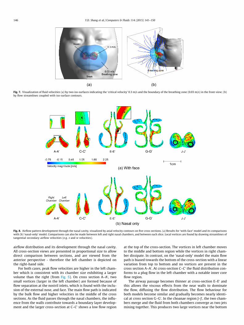
Fig. 7. Visualization of fluid velocities (a) by two iso-surfaces indicating the ‘critical velocity’ 0.3 m/s and the boundary of the breathing zone (0.03 m/s) in the front view; (b)by flow streamlines coupled with iso-surface contours.
Fig. 8. Airflow pattern development through the nasal cavity, visualized by axial velocity contours on five cross sections. (a) Results for ‘with-face’ model and its comparisonswith (b) ‘nasal-only’ model. Comparisons can also be made between left and right nasal chambers, and between each slice. Local vortices are found by drawing streamlines oftangential secondary airflow velocities (e.g. v and w velocities).
146 Y.D. Shang et al. / Computers & Fluids 114 (2015) 141–150
airflow distribution and its development through the nasal cavity.All cross-section views are presented in proportional size to allowdirect comparison between sections, and are viewed from theanterior perspective - therefore the left chamber is depicted onthe right-hand side.
For both cases, peak flow velocities are higher in the left cham-ber which is consistent with its chamber size exhibiting a largervolume than the right (from Fig. 5). On cross section A–A0, twosmall vortices (larger in the left chamber) are formed because offlow separation at the nostril inlets, which is found with the inclu-sion of the external nose, and face. The main flow path is indicatedby the bulk flow and higher velocities in the middle of the crosssections. As the fluid passes through the nasal chambers, the influ-ence from the walls contribute towards a boundary layer develop-ment and the larger cross-section at C–C0 shows a low flow region
at the top of the cross-section. The vortices in left chamber movesto the middle and bottom region while the vortices in right cham-ber dissipate. In contrast, on the ‘nasal-only’ model the main flowpath is biased towards the bottom of the cross-section with a linearvariation from top to bottom and no vortices are present in thecross section A–A0. At cross-section C–C0 the fluid distribution con-forms to a plug flow in the left chamber with a notable inner coreflow region.
The airway passage becomes thinner at cross-section E–E0 andthis allows the viscous effects from the near walls to dominatethe flow, diffusing the flow distribution. The flow behaviour forboth models become similar and gradually becomes nearly identi-cal at cross section G–G0. In the choanae region J–J0, the two cham-bers merge and the fluid from both chambers converge as two jetsmixing together. This produces two large vortices near the bottom

Fig. 9. Aspiration ratio against particle size comparison between numerical resultsand reported experimental data by Hsu and Swift [48] and numerical data by Naseriand Abouali [49].
Fig. 10. Micro particle deposition efficiency comparison between numerical resultsand reported experimental data by Hsu and Chuang [52], Kelly et al. [50], andSchroeter et al. [51].
Fig. 11. Breathing zone structure and particle tracks with inertial parameter I = 1.6e+3, 2.outside space (a) Flow rate = 10 L/min, particle size = 3.06 lm, 12.25 lm and 24.5 lm (b
Y.D. Shang et al. / Computers & Fluids 114 (2015) 141–150 147
of the cross-section. One difference is an additional small vortexfound in the ‘nasal-only’ model at the top left region. Overall theinfluence of the external environment and facial features disturbsthe flow up until cross-section E–E0 where the narrowed passage-ways allow the viscous effects to diffuse any flow differencesbetween the two models. Beyond the E–E0 cross-section, the flowdistribution becomes similar.
The difference between the two cases are subject to the airflowconditions occurring at the nostril inlets. The comparison indicates,that inclusion of the external nose and a breathing zone signifi-cantly influences the airflow as far as cross section E–E0, beforethe surrounding walls diffuse the variations. Gaining insight intothe flow behaviour can help to understand particle transport prop-erties to: (i) predict inhaled particle deposition sites in the nasalcavity; (ii) determine which regions of the nasal cavity influencesthe particle deposition patterns; and (iii) predict the effects ofbiased flow rates between the two chambers on different heav-ier/lighter particle transport and; predict whether recirculationregions, which are caused by the low flow region at C–C0, haveany influence on particle deposition especially on the olfactorysensors.
3.3. Verification for particle simulation
To verify the particle tracking in the outside space, the aspira-tion ratio(AR) against particle size is simulated and compared withHsu and Swift [48]’s experimental result and Naseri and Abouali[49]’s numerical result. Hsu’s [48] work showed that breathingcondition do not affect the aspiration ratio significantly, hencethe flow rate in this validation is fixed to 15 L/min. For this veri-fication case, 1 million particles with the density identical to thosein the experiment are released from the top surface (e.g. the ceil-ing) of the outside space. The AR is defined as:
AR ¼ AcVc
AnVnð6Þ
where Ac is the ’critical area’ in the top surface and An is the totalarea of nostrils. Vc is the settling velocity of the particle
Vsettling ¼ qpd2pg=18lf and Vn is the average velocity on nostrils.
Fig. 9 indicates the numerical results in this study are in good agree-ment with both reported data for particles smaller than 40 lm andmatches Naseri’s [49] data for particles larger than 40 lm.
For micron sized particles, its deposition can be approximatelypredicted by the inertial parameter, I which considers the particle
5e+4 and 1e+5 representing low, medium and high inertial types, respectively, in the) Flow rate = 15 L/min, particle size = 2.5 lm, 10 lm and 20 lm.

148 Y.D. Shang et al. / Computers & Fluids 114 (2015) 141–150
mass to the square power, and the averaged fluid momentum. Theinertial parameter is defined as:
I ¼ d2Q ð7Þ
Fig. 12. Low, medium and high inertial particle deposition efficiency in the nasalcavity under flow rate 10 L/min and 15 L/min.
Fig. 13. Comparisons of particle depositions in the 3D transparent image and on the normDeposition patterns in 3D transparent models and in mapped 2D domains for particle s
where Q is the volume flow rate (cm3/s) and d (lm) is the aerody-namic diameter. The deposition efficiencies of particles rangingfrom 0.4 lm to 30 lm as a function of inertial parameter are shownin Fig. 10. For consistency with the reported experimental andnumerical data, particles were released uniformly from the nostrilsusing the ‘nasal-only’ model. For inertial parameter less than 104,the numerical result shows good agreement with Kelly et al. [50](SLA,VIPER) and Schroeter et al. [51] (Model A, B, C), and lower thanHsu et al. [52]. While for inertial parameter larger than 104, thenumerical result matches Hsu et al. [52] result more. When compar-ing with [51] three models of different surface roughness, thedeposition efficiency of NC03 is higher than that of the smoothestmodel C, but lower than that of the roughest model A, and fits thatof the model B the best. Considering variation among different nasalcavities, the numerical result of particle deposition efficiency iswithin range with reported data.
3.4. Particle behaviour influenced by different flow rate
Despite the inertial parameter, the structure of the breathingzone and the gravity also have influence on particle behaviour.To reveal these two effects on particles, particle tracks in the out-side space and deposition efficiency in the nasal cavity under twoflow rates 15 L/min and 10 L/min are investigated with three
alized 2D surface-mapped domain. (a) mapping division for the nasal cavity. (b–d)izes of 2.5 lm, 10 lm and 20 lm respectively.

Y.D. Shang et al. / Computers & Fluids 114 (2015) 141–150 149
particle types representing low, medium and high inertia(I = 1.6e+3, 2.5e+4 and 1.0e+5). It’s corresponding particle sizesare 2.5 lm, 10 lm and 20 lm for flow rate 15 L/min, and3.06 lm, 12.25 lm and 24.5 lm for a flow rate of 10 L/min(Figs. 11 and 12).
A similar breathing zone is found for the two flow rates (Fig. 11)where the region extends to 2.34 cm horizontal to the nose tip. Thethree low, medium, and high inertial particles were released fromlocation ‘O’ for both flow rates. Similar trajectories for the low andmedium inertial particles were found between the two flow rates.There was a greater difference in the trajectory of the high inertialparticle, caused by the relatively increased influence of gravity.After inhalation the particle deposition efficiencies (Fig. 12) indi-cate that both flow rates produce similar deposition except forthe medium inertial particle (I = 2.5e+4), which had a differenceof 8.6%.
3.5. Particle deposition at a flow rate of 15 L/min
Local particle deposition patterns for 2.5 lm, 10 lm and 20 lmparticles representing PM2.5, PM10 and larger ambient particlesrespectively, are presented in both 3D transparent models andmapped 2D domains in Fig. 13(b)–(d). The mapping division forthe nasal cavity is shown again in Fig. 13(a) as reference. For eachcase, the particle deposition in the left chamber is higher than inthe right chamber, caused by the increased flow rate, thereby ahigher inertial parameter in left chamber. In general, there arethree highly localized deposition hot spots. Two of these regionsare located at: (i) top of vestibule and; (ii) at the nasal pharynxregion. These locations are downstream of 90-degree bends (fromthe nostril into the main nasal passage, and the nasopharynx bendin the posterior nasal cavity) [28] where the higher inertial parti-cles with reduced particle response times, are unable turn and fol-low the curved flow streamlines. The third hot spot is located at thecommon boundary of the middle turbinate and the middle meatus(region-8), as large amount of particles directly impact into it soonafter being inhaled into the nasal cavity.
For 2.5 lm, deposition pattern tends to disperse through thewhole nasal cavity. The only difference between the two modellingcases is that particles are more concentrated at the top of vestibuleand left olfactory region for the ‘with-face’ model. As the particlesize becomes larger to 10 lm, fewer particles deposit in vestibule
Fig. 14. Comparison of deposition efficiency between ‘nasal-only’ and ‘with-face’cases. This inertial range corresponds to particle sizes of approximately 7.8 lm and20 lm respectively for an inhalation rate of 15 L/min (e.g. 250 cm3/s).
region for the ‘with-face’ model and this is compensated with anincrease in deposition in the posterior nasal regions. For the‘nasal-only’ case however, the vestibule region remains a highdeposition region and its deposition efficiency is much higher.When the particle size increases to 20 lm, significant differencesin the deposition patterns are found between the two models,although deposition efficiency remains similar. For the ‘nasal-only’case, particles mainly deposit in four regions: vestibule, nasalatrium, middle turbinate and septum region. However, for the‘with-face’ model, there are few particles depositing near the nos-trils, but rather deposition occurs on the nasal atrium region andinferior turbinate regions.
3.6. Influence of breathing zone on particle transport at 15 L/min
The airflow patterns in the breathing zone has an influence onthe inhaled particle conditions at the nostrils and in turn deposi-tion patterns in the nasal cavity. To determine the influence ofthe external nose and breathing zone, the deposition efficiency asa function of inertial parameter is shown in Fig. 14 for the twomodels. For an inertial parameter less than 104, the depositionefficiencies are generally very similar. However, for the inertialparameter range from 1:5� 104 to 1� 105 the deposition effi-ciency for the ‘with-face’ model becomes significantly smaller,which indicates different particle entry positions in the nostrils.For the ‘nasal-only’ model, heavy particles released uniformly nearthe nostril edges tend to impact directly on the vestibule region.This unrealistic boundary condition is avoided when the particlesare transported from outside of the nose and allowed to enternaturally, entrained in the flow.
4. Conclusion
A new numerical nasal cavity model labelled as ‘NC03’, com-bined with detailed facial features was reconstructed from CTscans to determine the influence of the airflow field and breathingzone on micro particle deposition inside the nasal cavity. To gainbetter visualization of particle deposition patterns, a surface map-ping technique was used by dividing the nasal cavity into detailedsections according to anatomy, and further normalizing themapped domain.
Under a light breathing flow rates of 15 L/min, the airflow in theexternal domain remained uniform before entering the breathingzone of 3 cm from nostrils. It was shown that additional vorticeswere generated in the nasal cavity from the external environmentwhich is not found for the ‘nasal-only’ model that omitted the out-side condition. Differences in airflow patterns were found betweenthe two models, particularly in the vestibule region, but then theflow patterns became similar by the main nasal passages.
The outside ambient particles were mainly subjected to thegravitational force but gradually were influenced by the inhaledair. Within the breathing region, the particles accelerated rapidlyby the inhaled air into a smaller cross section avoiding directimpaction on the vestibule region. This led to particles penetratingthe nasal cavity deeper transferring to posterior regions. Wheninfluenced by the breathing zone, particle deposition efficienciesof particle size range from 7.8 lm to 20 lm became significantlylower (maximum of 37.7% lower for 12 lm particles). Particles of2.5 lm particles were negligible influenced by the breathing zoneand dispersed through the whole nasal cavity; 10 lm particleswere transferred by the vortices to the posterior nasal regionsand; 20 lm particles directly impacted on the nasal atrium regionand inferior turbinate regions.
These results suggest that omitting the external nose andbreathing region causes a change in the fluid flow within the

150 Y.D. Shang et al. / Computers & Fluids 114 (2015) 141–150
anterior nasal cavity half, and also significant changes in thedeposition efficiency for mid-inertial parameter particles.
Acknowledgements
The authors would like to gratefully acknowledge the financialsupport provided by the National Basic Research Program (973) ofChina (Grant No. 2012CB720100), the Natural Science Foundationof China (Grant No. 21277080) and the Australian ResearchCouncil (Project ID:DP120103958). The assistance of resourcesprovided at the NCI National Facility Systems at the AustralianNational University through the National Computational MeritAllocation Scheme supported by the Australian Government is alsograteful.
References
[1] Kelly JT, Prasad AK, Wexler AS. Detailed flow patterns in the nasal cavity. J ApplPhysiol 2000;89:323–37.
[2] Chung S-K, Kim S. Digital particle image velocimetry studies of nasal airflow.Respir Physiol Neurobiol 2008;163:111–20.
[3] Croce C, Fodil R, Durand M, Sbirlea-Apiou G, Caillibotte G, Papon J, et al. In vitroexperiments and numerical simulations of airflow in realistic nasal airwaygeometry. Ann Biomed Eng 2006;34:997–1007.
[4] Doorly DJ, Taylor DJ, Schroter RC. Mechanics of airflow in the human nasalairways. Respir Physiol Neurobiol 2008;163:100–10.
[5] Doorly D, Taylor D, Franke P, Schroter R. Experimental investigation of nasalflow. Proc. Inst Mech Eng Part H – J Eng Med 2008;222:439–53.
[6] Keyhani K, Scherer PW, Mozell MM. A numerical model of nasal odoranttransport for the analysis of human olfaction. J Theor Biol 1997;186:279–301.
[7] Wen J, Inthavong K, Tu J, Wang SM. Numerical simulations for detailed airflowdynamics in a human nasal cavity. Respir Physiol Neurobiol 2008;161:125–35.
[8] Horschler I, Meinke M, Schroder W. Numerical simulation of the flow field in amodel of the nasal cavity. Comput Fluids 2003;32:39–45.
[9] Horschler I, Schroder W, Meinke M. On the assumption of steadiness of nasalcavity flow. J Biomech 2010;43:1081–5.
[10] Inthavong K, Wen J, Tu J, Tian Z. From ct scans to cfd modelling–fluid and heattransfer in a realistic human nasal cavity. Eng Appl Comput Fluid Mech2009;3:321–35.
[11] Elad D, Wolf M, Keck T. Air-conditioning in the human nasal cavity. RespirPhysiol Neurobiol 2008;163:121–7.
[12] Garcia G, Bailie N, Martins D, Kimbell J. Atrophic rhinitis: a cfd study of airconditioning in the nasal cavity. J Appl Physiol 2007;103:1082–92.
[13] Zhao K, Pribitkin EA, Cowart BJ, Rosen D, Scherer PW, Dalton P. Numericalmodeling of nasal obstruction and endoscopic surgical intervention: Outcometo airflow and olfaction. Am J Rhinol 2006;20:308–16.
[14] Chen X, Lee H, Chong V, Wang dY. Numerical simulation of the effects ofinferior turbinate surgery on nasal airway heating capacity. Am J RhinolAllergy 2010;24:118–22.
[15] Moghadas H, Abouali O, Faramarzi A, Ahmadi G. Numerical investigation ofseptal deviation effect on deposition of nano/microparticles in human nasalpassage. Respir Physiol Neurobiol 2011;177:9–18.
[16] Abouali O, Keshavarzian E, Ghalati PF, Faramarzi A, Ahmadi G, Bagheri MH.Micro and nanoparticle deposition in human nasal passage pre and postvirtual maxillary sinus endoscopic surgery. Respir Physiol Neurobiol2012;181:335–45.
[17] Na Y, Chung KS, Chung S-K, Kim SK. Effects of single-sided inferiorturbinectomy on nasal function and airflow characteristics. Respir PhysiolNeurobiol 2012;180:289–97.
[18] Cheng Y, Holmes T, Gao J, Guilmette R, Li S, Surakitbanharn Y, et al.Characterization of nasal spray pumps and deposition pattern in a replica ofthe human nasal airway. J Aerosol Med 2001;14:267–80.
[19] Inthavong K, Tian ZF, Li H, Tu JY, Yang W, Xue C, et al. A numerical study ofspray particle deposition in a human nasal cavity. Aerosol Sci Technol2006;40:1034–45.
[20] Kimbell J, Segal R, Asgharian B, Wong B, Schroeter J, Southall J, et al.Characterization of deposition from nasal spray devices using a computationalfluid dynamics model of the human nasal passages. JAerosol Med2007;20:59–74.
[21] Fung M, Inthavong K, Yang W, Tu J. Cfd modeling of spray atomization for anasal spray device. Aerosol Sci Technol 2012;46:1219–26.
[22] Inthavong K, Zhang K, Tu J. Numerical modelling of nanoparticle deposition inthe nasal cavity and the tracheobronchial airway. Comput Methods BiomechBiomed Eng 2011;14:633–43.
[23] Frederick CB, Gentry PR, Bush ML, Lomax LG, Black KA, Finch L, et al. A hybridcomputational fluid dynamics and physiologically based pharmacokineticmodel for comparison of predicted tissue concentrations of acrylic acid andother vapors in the rat and human nasal cavities following inhalationexposure. Inhal Toxicol 2001;13:359–76 [PMID: 11295868].
[24] Kimbell JS. Nasal dosimetry of inhaled gases and particles: where do inhaledagents go in the nose? Toxicol Pathol 2006;34:270–3.
[25] Tian Z, Inthavong K, Tu J. Deposition of inhaled wood dust in the nasal cavity.Inhal Toxicol 2007;19:1155–65.
[26] Inthavong K, Tian Z, Tu J, Yang W, Xue C. Optimising nasal spray parameters forefficient drug delivery using computational fluid dynamics. Comput Biol Med2008;38:713–26.
[27] Karakosta P, Alexopoulos AH, Kiparissides C. Computational model of particledeposition in the nasal cavity under steady and dynamic flow. ComputMethods Biomech Biomed Eng 2013.
[28] Wang SM, Inthavong K, Wen J, Tu JY, Xue CL. Comparison of micron- andnanoparticle deposition patterns in a realistic human nasal cavity. RespirPhysiol Neurobiol 2009;166:142–51.
[29] Shi H, Kleinstreuer C, Zhang Z. Modeling of inertial particle transport anddeposition in human nasal cavities with wall roughness. J Aerosol Sci2007;38:398–419.
[30] Shanley KT, Zamankhan P, Ahmadi G, Hopke PK, Cheng Y-S. Numericalsimulations investigating the regional and overall deposition efficiency of thehuman nasal cavity. Inhal Toxicol 2008;20:1093–100 [PMID: 18800272].
[31] Kennedy N, Hinds W. Inhalability of large solid particles. J Aerosol Sci2002;33:237–55.
[32] Anthony T, Flynn M. Computational fluid dynamics investigation of particleinhalability. Aerosol Sci 2006;37:750–65.
[33] Anthony T. Contribution of facial feature dimensions and velocity parameterson particle inhalability. Ann Occup Hyg 2010;54:710–25.
[34] Taylor DJ, Doorly DJ, Schroter RC. Inflow boundary profile prescription fornumerical simulation of nasal airflow. J R Soc Interface 2010;7:515–27.
[35] Zhu JH, Lee HP, Lim KM, Lee SJ, Wang DY. Evaluation and comparison of nasalairway flow patterns among three subjects from caucasian, chinese and indianethnic groups using computational fluid dynamics simulation. Respir PhysiolNeurobiol 2011;175:62–9.
[36] Lu J, Han D, Zhang L. Accuracy evaluation of a numerical simulation model ofnasal airflow. Acta Oto-laryngologica 2014;134:513–9 [PMID: 24702230].
[37] Se CMK, Inthavong K, Tu JY. Inhalability of micron particles through the noseand mouth. Inhal Toxicol 2010;22:287–300.
[38] Inthavong K, Ge QJ, Li XD, Tu JY. Source and trajectories of inhaled particlesfrom a surrounding environment and its deposition in the respiratory airway.Inhal Toxicol 2013;25:280–91.
[39] Li XD, Inthavong K, Tu JY. Particle inhalation and deposition in a human nasalcavity from the external surrounding environment. Build Environ2012;47:32–9.
[40] Ge Q, Inthavong K, Tu J. Local deposition fractions of ultrafine particles in ahuman nasal-sinus cavity cfd model. Inhal Toxicol 2012;24:492–505.
[41] Tenenbaum JB, de Silva V, Langford JC. A global geometric framework fornonlinear dimensionality reduction. Science 2000;290:2319–+.
[42] Inthavong K, Shang YD, Tu JY. Surface mapping for visualization of wallstresses during inhalation in a human nasal cavity. Respir Physiol Neurobiol2014;190:54–61.
[43] Si XHA, Xi JX, Kim J, Zhou Y, Zhong HL. Modeling of release position andventilation effects on olfactory aerosol drug delivery. Respir Physiol Neurobiol2013;186:22–32.
[44] Hahn I, Scherer PW, Mozell MM. Velocity profiles measured for air-flowthrough a large-scale model of the human nasal cavity. J Appl Physiol1993;75:2273–87.
[45] Morsi S, Alexander AJ. An investigation of particle trajectories in two-phaseflow systems. J Fluid Mech 1972;55:193–208.
[46] Lang J. Clinical anatomy of the nose, nasal cavity and paranasalsinuses. Stuttgart, Germany: George Thieme Verlag; 1989.
[47] Anthony TR, Flynn MR, Eisner A. Evaluation of facial features on particleinhalation. Ann Occup Hyg 2005;49:179–93.
[48] Hsu DL, Swift DJ. The measurements of human inhalability of ultralargeaerosols in calm air using mannikins. J Aerosol Sci 1999;30:1331–43.
[49] Naseri OGPFAG, Abouali A. Numerical investigation of regional particledeposition in the upper airway of a standing male mannequin in calm airsurroundings. Comput Biol Med 2014;52:73–81.
[50] Kelly JT, Asgharian B, Kimbell JS, Wong BA. Particle deposition in human nasalairway replicas manufactured by different methods. part i: inertial regimeparticles. Aerosol Sci Technol 2004;38:1063–71.
[51] Schroeter JD, Garcia GJM, Kimbell JS. Effects of surface smoothness on inertialparticle deposition in human nasal models. J Aerosol Sci 2011;42:52–63.
[52] Hsu DJ, Chuang MH. In-vivo measurements of micrometer-sized particledeposition in the nasal cavities of taiwanese adults. Aerosol Sci Technol2012;46:631–8.